data sheet t 8310-1/4/5/6 en - samson.de · 0.6 to 3.0 0.9 to 3.3 12 1.44 7.2 – – – 2.4 4.8...
TRANSCRIPT
SAMSON AKTIENGESELLSCHAFT · Weismüllerstraße 3 · 60314 Frankfurt am Main, Germany Phone: +49 69 4009-0 · Fax: +49 69 4009-1507 · [email protected] · www.samson.de
Data Sheet T 8310-1/4/5/6 EN
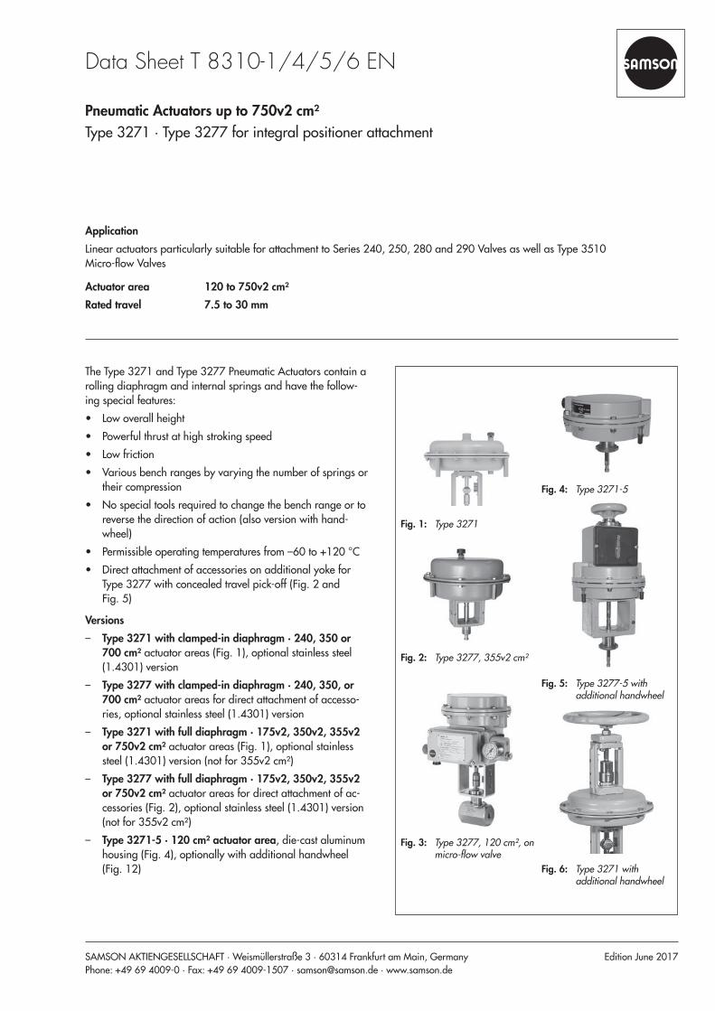
ApplicationLinear actuators particularly suitable for attachment to Series 240, 250, 280 and 290 Valves as well as Type 3510 Micro-flow Valves
Actuator area 120 to 750v2 cm²Rated travel 7.5 to 30 mm
Pneumatic Actuators up to 750v2 cm²Type 3271 · Type 3277 for integral positioner attachment
Edition June 2017
The Type 3271 and Type 3277 Pneumatic Actuators contain a rolling diaphragm and internal springs and have the follow-ing special features:
• Low overall height • Powerful thrust at high stroking speed • Low friction • Various bench ranges by varying the number of springs or
their compression • No special tools required to change the bench range or to
reverse the direction of action (also version with hand-wheel)
• Permissible operating temperatures from –60 to +120 °C • Direct attachment of accessories on additional yoke for
Type 3277 with concealed travel pick-off (Fig. 2 and Fig. 5)
Versions – Type 3271 with clamped-in diaphragm · 240, 350 or
700 cm² actuator areas (Fig. 1), optional stainless steel (1.4301) version
– Type 3277 with clamped-in diaphragm · 240, 350, or 700 cm² actuator areas for direct attachment of accesso-ries, optional stainless steel (1.4301) version
– Type 3271 with full diaphragm · 175v2, 350v2, 355v2 or 750v2 cm² actuator areas (Fig. 1), optional stainless steel (1.4301) version (not for 355v2 cm²)
– Type 3277 with full diaphragm · 175v2, 350v2, 355v2 or 750v2 cm² actuator areas for direct attachment of ac-cessories (Fig. 2), optional stainless steel (1.4301) version (not for 355v2 cm²)
– Type 3271-5 · 120 cm² actuator area, die-cast aluminum housing (Fig. 4), optionally with additional handwheel (Fig. 12)
Fig. 1: Type 3271
Fig. 2: Type 3277, 355v2 cm²
Fig. 3: Type 3277, 120 cm², on micro-flow valve
Fig. 4: Type 3271-5
Fig. 5: Type 3277-5 with additional handwheel
Fig. 6: Type 3271 with additional handwheel

2 T 8310-1/4/5/6 EN
Principle of operationThe signal pressure pst creates the force F = pst · A at the dia-phragm surface A which is opposed by the springs (10) in the actuator. The bench range is determined by the number of springs used and their compression, taking into account the rated travel. The travel H is proportional to the signal pressure pst. The direction of action of the actuator stem (7) depends on how the springs are installed in the actuator and the location of the signal pressure connection (S).Actuators with 175v2, 350v2, 355v2, and 750v2 cm² actua-tor areas are designed with a full rolling diaphragm (see Fig. 10). The diaphragm of actuators with 240, 350, and 700 cm² actuator areas is clamped-in (see Fig. 9).The stem connector (26) connects the actuator stem (7) with the plug stem of the valve.The adjustable mechanical travel stop (Fig. 14) is suitable for actuators with actuator areas of 120, 175v2, 240, 350v2, 355, 700 or 750v2 cm². Using the travel stop, the actuator travel can be limited by up to 50 % in both directions (actua-tor stem extends or retracts) and permanently adjusted.
Direction of actionActuators are available with the following directions of action: – Actuator stem extends (FA): the springs cause the actuator
stem to move to the lower end position (sectional draw-ings, right) when the diaphragm is relieved of pressure or when the supply air fails.
– Actuator stem retracts (FE): the springs cause the actuator stem to retract (sectional drawings, left) when the dia-phragm is relieved of pressure or when the supply air fails.
S
102
168
16
1
S
4
726
Fig. 7: Type 3271 · Right: with additional springs
2
1
410
8
S 7
Fig. 8: Type 3277-5 for direct attachment of accessories (120 cm²)
– Type 3277-5 · 120 cm² actuator area, die-cast aluminum housing for direct attachment of accessories (Fig. 8), op-tionally with additional handwheel (Fig. 5)
– Type 3271 or Type 3277 · Additional handwheel for ac-tuators with actuator areas from 175v2 to 750v2 cm² (Fig. 6 and Fig. 11)
– Type 3271 · Travel stop (Fig. 14), minimum and maxi-mum travel mechanically adjustable in versions with 175v2 to 750v2 cm²
Further versions – Type 3273 Side-mounted Handwheel u T 8312 – Type 3271 or Type 3277 · Combined version with hand-
wheel and travel stops on both sides for 175v2 to 750v2 cm² actuator areas (Fig. 14)
– Versions for other control media (e.g. water) available on request
T 8310-1/4/5/6 EN 3
S
1
S
410
7
8
26
16
2
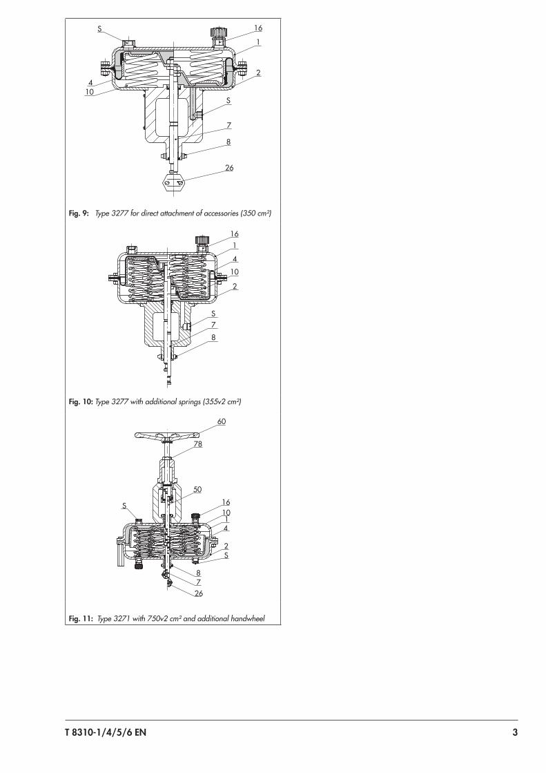
Fig. 9: Type 3277 for direct attachment of accessories (350 cm²)
1
S
2
10
4
16
78
Fig. 10: Type 3277 with additional springs (355v2 cm²)
78
1610
78
60
50
1
S
2
26
S
4
Fig. 11: Type 3271 with 750v2 cm² and additional handwheel

4 T 8310-1/4/5/6 EN
Fig. 12: Type 3271-5, “stem extends” fail-safe action, with additional handwheel
73
S
102
168
785077
1614
S
726
70
Fig. 13: Type 3271 with adjustable travel stop
Fig. 14: Type 3271 (175v2 cm²) · Combined version with hand-wheel and travel stops on both sides
Legend for Fig. 7 to Fig. 141 Top diaphragm case2 Bottom diaphragm case4 Diaphragm7 Actuator stem8 Ring nut
10 Springs16 Vent plug26 Stem connector50 Actuator stem60 Handwheel
70 Nut73 Cover77 Dry bearing78 Lock nutS Signal pressure connection

T 8310-1/4/5/6 EN 5
Table 2: Technical data for additional handwheelVersion for actuator Type 3271-5 · Type 3277-5 Type 3271 · Type 3277
Actuator area 120 cm²175v2, 240, 350, 350v2, 355v2 cm²
700 cm² (only for spring upper range value ≤3.3 bar)750v2 cm² (only for spring upper range value ≤3.1 bar)
Material
Housing See Table 1
Spindle 1.4305 Stainless steel 1.4104
Handwheel Aluminum, powder paint coated Cast iron EN-GJL-250 (EN-JL1040), powder paint coated
Table 1: Technical data for Type 3271 and Type 3277 Pneumatic Actuators
Actuator area cm² 240 · 350 · 700 175v2 · 350v2 · 355v2 · 750v2 120Type 3271-5/Type 3277-5
Diaphragm Clamped-in Full –
Max. supply pressure 6 bar 1)
Permissible ambient temperatures
Diaphragm material NBR: –35 to +90 °C 2) 4)
Diaphragm material NBR:–35 to +80 °C 2)
Diaphragm material EPDM: –50 to +120 °C 3) 4)
– Diaphragm material PVMQ:–60 to +90 °C 4)
Compliance
Materials
Actuator stem 1.4404 1.4305
Actuator stem sealingNBR
NBREPDM
Housing
1.0332/1.0335Sheet steel, painted
Ambient temperature ≥–50 °C
1.0976/1.0982Sheet steel, painted
Ambient temperature ≥–60 °C Die-cast aluminum, painted
1.4301 · Stainless sheet steel · Ambient temperature ≥–60 °C 5)
1) Observe supply pressure restrictions.2) In on/off service, lowest temperature restricted to –20 °C3) In on/off service, lowest temperature restricted to –40 °C4) Install vent plug (u AB 07) for temperatures below –20 °C.5) 1.4301 not available for 355v2 cm²

6 T 8310-1/4/5/6 EN
Table 3: Bench ranges for pneumatic actuators up to 750v2 cm² actuator areaAc
tuat
or a
rea
in cm
²
Rate
d tra
vel i
n m
m
Trav
el v
olum
e at
rate
d tra
vel i
n dm
³
Dead
vol
ume
in d
m³
Max
. tra
vel i
n m
m 1)
2)
Benc
h ra
nge
in b
ar(S
igna
l pre
ssur
e ra
nge
at ra
ted
trave
l)
Add.
pos
sible
sprin
g co
mpr
essio
n in
%
Ope
ratin
g ra
nge
with
sprin
g co
mpr
essio
n in
bar
No.
of s
prin
gs
Sprin
g fo
rce
at 0
mm
trav
el in
kN
1)
Sprin
g fo
rce
at ra
ted
trave
l in
kN
Thrust in kN at rated travel and supply pressure in bar of
1.4 2.0 3.0 4.0 5.0 6.0
120 7.5 0.09 0.12 9
0.4 to 0.8
0
– 3 0.48 0.96 0.72 1.44 2.64 3.84 5.04 6.24
0.8 to 1.6 – 6 0.96 1.92 – 0.48 1.68 2.88 4.08 5.28
Version forType 3510 Micro-flow Valve
1.7 to 2.1 3) 1.7 to 2.1 6 2.04 2.52 – – 1.08 2.28 3.48 4.68
2.4 to 3.0 3) 2.4 to 3.0 12 2.88 3.6 – – – 1.2 2.4 3.6
120 15 0.2 0.10
170.2 to 1.0
0
– 3 0.24 1.2 – 1.2 2.4 3.6 4.8 6
0.4 to 2.0 – 6 0.48 2.4 – – 1.2 2.4 3.6 4.8
151.4 to 2.3 3) – 6 1.68 2.76 – – 0.84 2.04 3.24 4.44
2.1 to 3.3 3) – 12 2.52 3.96 – – – 0.84 2.04 3.24
175v2 15 0.26 0.24 19
0.2 to 1.0
25
0.4 to 1.2 3 0.35 1.75 0.7 1.75 3.5 5.25 7 8.75
0.4 to 2.0 0.8 to 2.4 6 0.7 3.5 – – 1.75 3.5 5.25 7
0.5 to 2.5 1.0 to 3.0 9 0.88 4.38 – – 0.88 2.63 4.38 6.13
0.6 to 3.0 1.2 to 3.6 12 1.05 5.25 – – – 1.75 3.5 5.25
1.3 to 2.9 1.7 to 3.3 12 2.28 5.08 – – 0.18 1.93 3.68 5.43
240 15 0.36 0.38 17
0.2 to 1.0
12.5
0.3 to 1.1 3 0.48 2.4 0.96 2.4 4.8 7.2 9.6 12
0.4 to 2.0 0.6 to 2.2 6 0.96 4.8 – – 2.4 4.8 7.2 9.6
0.6 to 3.0 0.9 to 3.3 12 1.44 7.2 – – – 2.4 4.8 7.2
350 15 0.53 0.6
22
0.2 to 1.0
25
0.4 to 1.2 3 0.7 3.5 1.4 3.5 7 10.5 14 17.5
0.4 to 2.0 0.8 to 2.4 6 1.4 7 – – 3.5 7 10.5 14
0.6 to 3.0 1.2 to 3.6 12 2.1 10.5 – – – 3.5 7 10.5
151.4 to 2.3 3)
01.4 to 2.3 6 4.9 8.05 – – 2.45 5.95 9.45 13
2.1 to 3.3 3) 2.1 to 3.3 12 7.35 11.6 – – – 2.45 5.95 9.45
350v2 15 0.54 0.45 19
0.2 to 1.0
25
0.4 to 1.2 3 0.7 3.5 1.4 3.5 7 10.5 14 17.5
0.4 to 2.0 0.8 to 2.4 6 1.4 7 – – 3.5 7 10.5 14
0.5 to 2.5 1.0 to 3.0 9 1.75 8.75 – – 1.75 5.25 8.75 12.25
0.6 to 3.0 1.2 to 3.6 12 2.1 10.5 – – – 3.5 7 10.5
1.4 to 2.3 1.7 to 2.6 6 4.9 8.05 – – 2.45 5.95 9.45 12.95
2.0 to 3.2 2.3 to 3.5 12 7 11.2 – – – 2.8 6.3 9.8
355v2 30 1.06 0.8 38
0.2 to 1.0
25
0.4 to 1.2 3 0.7 3.55 1.4 3.55 7.1 10.6 14.2 17.7
0.4 to 2.0 0.8 to 2.4 6 1.4 7.1 – – 3.55 7.1 10.6 14.2
0.6 to 3.0 1.2 to 3.6 12 2.1 10.6 – – – 3.55 7.1 10.6
0.9 to 1.7 1.1 to 1.9 4 3.2 6.0 – 1.1 4.6 8.2 11.7 15.3
1.4 to 2.6 1.75 to 2.95 8 5.0 9.2 – – 1.4 5.0 8.5 12.1
1.9 to 3.3 2.25 to 3.65 10 6.5 11.7 – – – 2.5 6.0 9.6

T 8310-1/4/5/6 EN 7
Actu
ator
are
a in
cm²
Rate
d tra
vel i
n m
m
Trav
el v
olum
e at
rate
d tra
vel i
n dm
³
Dead
vol
ume
in d
m³
Max
. tra
vel i
n m
m 1)
2)
Benc
h ra
nge
in b
ar(S
igna
l pre
ssur
e ra
nge
at ra
ted
trave
l)
Add.
pos
sible
sprin
g co
mpr
essio
n in
%
Ope
ratin
g ra
nge
with
sprin
g co
mpr
essio
n in
bar
No.
of s
prin
gs
Sprin
g fo
rce
at 0
mm
trav
el in
kN
1)
Sprin
g fo
rce
at ra
ted
trave
l in
kN
Thrust in kN at rated travel and supply pressure in bar of
1.4 2.0 3.0 4.0 5.0 6.0
700 30 2.1 2.4
38
0.2 to 1.0
25
0.4 to 1.2 3 1.4 7 2.8 7 14 21 28 35
0.4 to 2.0 0.8 to 2.4 6 2.8 14 – – 7 14 21 28
0.6 to 3.0 1.2 to 3.6 4) 12 4.2 21 – – – 7 14 21
30
1.4 to 2.3 3)
0
1.4 to 2.3 8 9.8 16.1 – – 4.9 11.9 18.9 25.9
2.1 to 3.3 3) 2.1 to 3.3 12 14.7 23.1 – – – 4.9 11.9 18.9
2.35 to 3.8 3) 4) 2.35 to 3.8 4) 15 16.5 26.6 – – – 1.4 8.4 15.4
2.6 to 4.3 3) 4) 2.6 to 4.3 4) 18 18.2 30.1 – – – – 4.9 11.9
750v2 30 2.17 1.28 38
0.2 to 1.0
25
0.4 to 1.2 3 1.5 7.5 3.0 7.5 15 22.5 30 37.5
0.4 to 2.0 0.8 to 2.4 6 3.0 15 – – 7.5 15 22.5 30
0.5 to 2.5 1.0 to 3.0 9 3.7 18.8 – – – 11.2 18.5 26.2
0.6 to 3.0 1.2 to 3.6 4) 12 4.5 22.5 – – – 7.5 15 22.5
1.4 to 2.4 1.65 to 2.65 9 10.5 18 – – 4.5 12 19.5 27
1.9 to 3.1 2.2 to 3.4 4) 14 14.3 23.3 – – – – – –
2.1 to 3.8 4) 5) 2.5 to 4.2 4) 5) 16 15.8 28.5 – – – – – –
2.3 to 4.2 4) 5) 2.8 to 4.7 4) 5) 17 17.3 31.5 – – – – – –
1) Based on lower bench range value, not taking zero travel (to unseat the plug) into account. 2) Zero travel as listed in Table 4 depending on fail-safe action3) Preloaded springs4) Version not available with top-mounted handwheel5) Not available with "stem retracts" fail-safe action

8 T 8310-1/4/5/6 EN
Dimensional drawings
HH6
H4
ØD
ØD2Ød
H1
HH5
H6H4
ØD
ØD2Ød
H8
Fig. 15: Type 3271-5 with additional handwheel Fig. 16: Type 3277-5 with travel stop
H6
max
. 58
ØD2
ØdM14 x 1
H6m
ax. 5
8
ØD2
ØdM14 x 1
10.5
10.5
Fig. 17: Type 3271-5 and Type 3277-5 with 7.5 mm travel for Type 3510 Micro-flow Valve
ØD1
H2H1
HH4
H6
ØD2Ød
ØD
a
a
ØD1
ØD
ØD2
55
Ød
H
H1
H4H6H5
a2
H2
a
a
a
HH8
H6
H4
ØD
ØD2Ød
Fig. 18: Type 3271 with additional handwheel Fig. 19: Type 3277 with additional handwheel Fig. 20: Type 3271 with travel stop
T 8310-1/4/5/6 EN 9
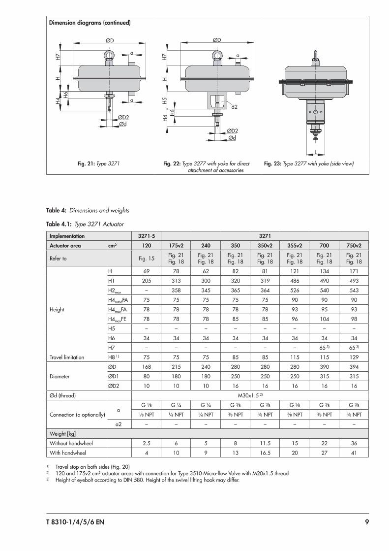
Table 4: Dimensions and weights
Table 4.1: Type 3271 Actuator
Implementation 3271-5 3271
Actuator area cm² 120 175v2 240 350 350v2 355v2 700 750v2
Refer to Fig. 15 Fig. 21Fig. 18
Fig. 21Fig. 18
Fig. 21Fig. 18
Fig. 21Fig. 18
Fig. 21Fig. 18
Fig. 21Fig. 18
Fig. 21Fig. 18
Height
H 69 78 62 82 81 121 134 171
H1 205 313 300 320 319 486 490 493
H2max – 358 345 365 364 526 540 543
H4ratedFA 75 75 75 75 75 90 90 90
H4maxFA 78 78 78 78 78 93 95 93
H4maxFE 78 78 78 85 85 96 104 98
H5 – – – – – – – –
H6 34 34 34 34 34 34 34 34
H7 – – – – – – 65 3) 65 3)
Travel limitation H8 1) 75 75 75 85 85 115 115 129
Diameter
ØD 168 215 240 280 280 280 390 394
ØD1 80 180 180 250 250 250 315 315
ØD2 10 10 10 16 16 16 16 16
Ød (thread) M30x1.5 2)
Connection (a optionally)a
G 1/8 G ¼ G ¼ G 3/8 G 3/8 G 3/8 G 3/8 G 3/8
1/8 NPT ¼ NPT ¼ NPT 3/8 NPT 3/8 NPT 3/8 NPT 3/8 NPT 3/8 NPT
a2 – – – – – – – –
Weight [kg]
Without handwheel 2.5 6 5 8 11.5 15 22 36
With handwheel 4 10 9 13 16.5 20 27 41
1) Travel stop on both sides (Fig. 20)2) 120 and 175v2 cm² actuator areas with connection for Type 3510 Micro-flow Valve with M20x1.5 thread3) Height of eyebolt according to DIN 580. Height of the swivel lifting hook may differ.
Dimension diagrams (continued)
a
a
HH6
H4
ØD
ØD2Ød
H7
HH7
a2
H5H4
H6
a
ØD
ØD2Ød
L
Fig. 21: Type 3271 Fig. 22: Type 3277 with yoke for direct attachment of accessories
Fig. 23: Type 3277 with yoke (side view)

10 T 8310-1/4/5/6 EN
Table 4.2: Type 3277 Actuator
Implementation 3277-5 3277
Actuator area cm² 120 175v2 240 350 350v2 355v2 700 750v2
Refer to (Fig. 16) Fig. 22Fig. 19
Fig. 22Fig. 19
Fig. 22Fig. 19
Fig. 22Fig. 19
Fig. 22Fig. 19
Fig. 22Fig. 19
Fig. 22Fig. 19
Height
H 70 78 65 82 81 121 135 171
H1 293 413 400 420 419 576 590 595
H2max – 458 445 465 464 626 640 643
H4ratedFA 75 75 75 75 75 90 90 90
H4maxFA 78 78 78 78 78 93 95 93
H4maxFE 78 78 78 85 85 96 104 98
H5 88 101 101 101 101 101 101 101
H6 34 34 34 34 34 34 34 34
H7 – – – – – – 65 3) 65 3)
Travel limitation H8 1) 75 75 75 85 85 115 115 129
Yoke width (see Fig. 23) L 70
Diameter
ØD 168 215 240 280 280 280 390 394
ØD1 80 180 180 250 250 250 315 315
ØD2 10 16 16 16 16 16 16 16
Ød (thread) M30x1.5 2)
Connection (a optionally)a
G 1/8 G ¼ G ¼ G 3/8 G 3/8 G 3/8 G 3/8 G 3/8
1/8 NPT ¼ NPT ¼ NPT 3/8 NPT 3/8 NPT 3/8 NPT 3/8 NPT 3/8 NPT
a2 – G 3/8 G 3/8 G 3/8 G 3/8 G 3/8 G 3/8 G 3/8
Weight [kg]
Without handwheel 3.2 10 9 12 15 19 26 40
With handwheel 4.5 14 13 17 20 24 31 45
1) Travel stop on both sides (Fig. 20)2) 120 and 175v2 cm² actuator areas with connection for Type 3510 Micro-flow Valve with M20x1.5 thread3) Height of eyebolt according to DIN 580. Height of the swivel lifting hook may differ.

T 8310-1/4/5/6 EN 11
Throttling or on/off serviceThe pneumatic actuators are designed for a maximum supply pressure of 6 bar when used for throttling service.In on/off service, the supply pressure must be limited.For the direction of action "actuator stem retracts (FE)", the permissible supply pressure must not exceed the upper bench range value by more than 3 bar:
Bench range Fail-safe action Max. supply pressure
0.2 to 1.0 barActuator stem
retracts
4 bar
0.4 to 2.0 bar 5 bar
0.6 to 3.0 bar 6 bar
With "stem extends" direction of action and travel stop, the supply pressure must not exceed the upper spring range value by more than 1.5 bar.
AccessoriesThe pneumatic actuators with 750v2 cm² actuator area have a female thread on the top diaphragm case to allow an eye-bolt or swivel lifting hook to be screwed into it. The eyebolt can be used to vertically lift the actuator and is included in the scope of delivery. The swivel lifting hook is designed for set-ting a control valve assembly upright or for lifting the actuator without valve. The swivel lifting hook can be ordered (accesso-ries).
Item no.
Actuator area Ring bolt(DIN 580) Swivel lifting hook
750v2 cm² 8325-0131 8442-1017
Actuators with 355v2 cm² actuator area or smaller do not re-quire a female thread or welded-on lifting eyelet due to their light weight. Actuators with 700 cm² actuator area have a welded-on lifting eyelet.
List of documentation
Device type Actuator area in cm² Data sheet Mounting and operating instruc-tions
Types 3271 and 3277 Pneumatic Actuators
120
Included in this data sheet
u EB 8310-1
240 · 350 · 700 u EB 8310-6
175v2 · 350v2 · 750v2 u EB 8310-5
355v2 u EB 8310-4
Type 3271 Pneumatic Actuator
1000u T 8310-2/7
u EB 8310-2
1400-120 · 2800 · 2 x 2800 u EB 8310-7
1400-60 u T 8310-3 u EB 8310-3
1400-250 u T 8310-8 u EB 8310-8
Ordering text
Actuator Type 3271Type 3277 for direct attachment of accessories
Actuator area … cm² Travel … mm
Optional HandwheelTravel stopCombined version with handwheel and travel stop on both sides
Bench range ... barDirection of action Actuator stem extends (FA)
Actuator stem retracts (FE)Signal pressure connection
G .../... NPT
Rolling diaphragm NBR/EPDM/PVMQ (175v2, 350v2, 355v2, and 750v2 cm² only)

Specifications subject to change without notice T 8310-1/4/5/6 EN 2018
-05-
25 ·
Engl
ish