data sheet pacdrive ish servo drive system - barr-thorp€¦ · procedure parameters value basis...
TRANSCRIPT
This document provided by Barr-Thorp Electric Co., Inc. 800-473-9123 www.barr-thorp.com
Legal notice© All rights remain with ELAU GmbH, even in the case of applications for propertyrights.No part of this documentation or the accompanying software and firmware may bereproduced, transferred, paraphrased, saved to a storage medium or translated toanother language or computer language without the written consent of ELAU GmbH.Every conceivable measure was taken to guarantee the correctness of this productdocumentation. However, since hardware and software are continuously improved,ELAU makes no representations or warranties with respect to the contents of thisdocumentation.All information on our products in this manual are given purely for the purpose of prod‐uct description and is not binding. Misprints, errors and modifications -without priornotice in the course of product development- are reserved. If details contained in thismanual are explicitly a part of an agreement made with ELAU GmbH, then the detailsof the agreements in this manual are exclusively to determine the agreed condition ofthe object of agreement, on behalf of the § 434 BGB (condition guarantee on behalfof legal regulations).
TrademarkPacDrive is a registered trademark of ELAU GmbH. All other trademarks mentioned in this documentation are the exclusive property oftheir manufacturers.ELAU is a registered trademark of Schneider Electric and/or its affliates in the UnitedStates and/or other countries. Other marks used herein may be the property of theirrespective owners.
ELAU GmbH Dillberg 12-16D-97828 Marktheidenfeld, GermanyPhone: +49 (0) 9391 / 606 - 0Fax: +49 (0) 9391 / 606 - 300e-mail: [email protected]: www.elau.de
Legal notice
Page 2 PacDrive iSH Servo Drive System ELAU GmbH
This document provided by Barr-Thorp Electric Co., Inc. 800-473-9123 www.barr-thorp.com
1 Overview
TM
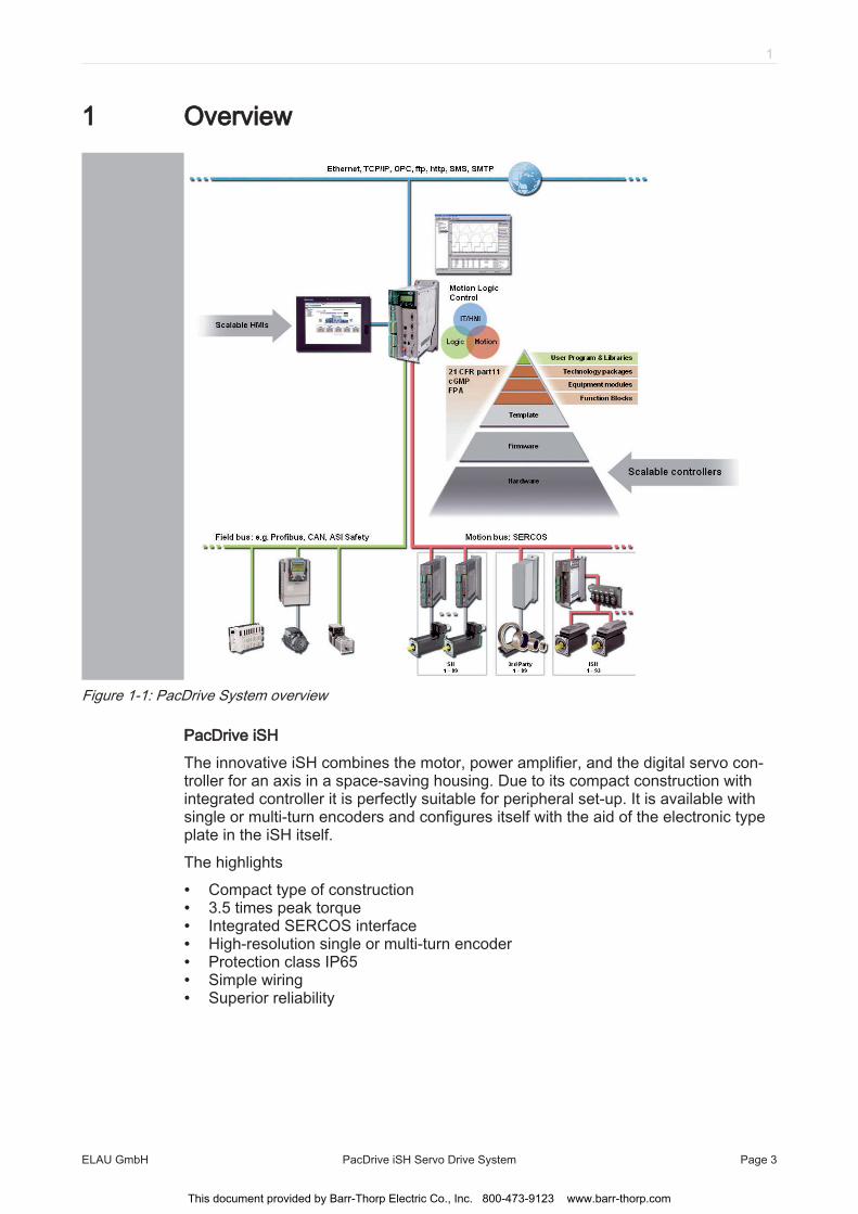
Figure 1-1: PacDrive System overview
PacDrive iSHThe innovative iSH combines the motor, power amplifier, and the digital servo con‐troller for an axis in a space-saving housing. Due to its compact construction withintegrated controller it is perfectly suitable for peripheral set-up. It is available withsingle or multi-turn encoders and configures itself with the aid of the electronic typeplate in the iSH itself.The highlights
• Compact type of construction• 3.5 times peak torque• Integrated SERCOS interface• High-resolution single or multi-turn encoder• Protection class IP65• Simple wiring• Superior reliability
1
ELAU GmbH PacDrive iSH Servo Drive System Page 3
This document provided by Barr-Thorp Electric Co., Inc. 800-473-9123 www.barr-thorp.com

PacDrive PS-5The PacDrive PS-5 Power Supply unit features modern technology and a compactand closed construction for switching cabinet installation. Each PacDrive iSH has aPacDrive PS-5 that can be quickly installed with a single connection line. Which meansthat the PS-5 fits seamlessly into the extremely flexible, modular drive concept.The highlights
• Integrated mains filter and bleeder• Intermediate circuit power for up to 25 iSH (depending on the application)• Integrated SERCOS interface• Fully diagnosable due to integrated controller• Simple mounting
PacDrive DB-5PacDrive DB-5 is the link between PS-5 and iSH. Optionally, 1 to 4 iSH Motors can beconnected depending on the number of drives. When operating more than 4 drivessimply expand the system using one or more DB-5s.The highlights
• 1-4 connections for iSH motors or easily expandable with more DB-5s• Easy to expand
1 Overview
Page 4 PacDrive iSH Servo Drive System ELAU GmbH
This document provided by Barr-Thorp Electric Co., Inc. 800-473-9123 www.barr-thorp.com
2 Technical data
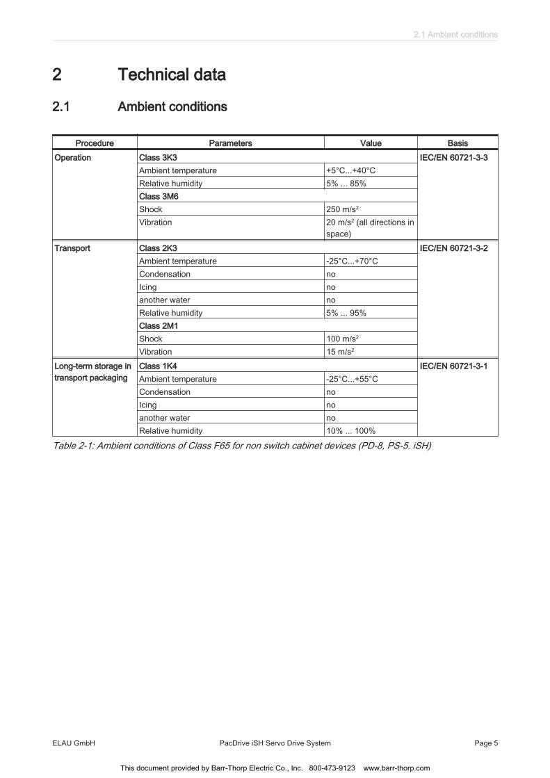
2.1 Ambient conditions
Procedure Parameters Value BasisOperation Class 3K3 IEC/EN 60721-3-3
Ambient temperature +5°C...+40°CRelative humidity 5% ... 85%Class 3M6Shock 250 m/s2
Vibration 20 m/s2 (all directions inspace)
Transport Class 2K3 IEC/EN 60721-3-2Ambient temperature -25°C...+70°CCondensation noIcing noanother water noRelative humidity 5% ... 95%Class 2M1Shock 100 m/s2
Vibration 15 m/s2
Long-term storage intransport packaging
Class 1K4 IEC/EN 60721-3-1Ambient temperature -25°C...+55°CCondensation noIcing noanother water noRelative humidity 10% ... 100%
Table 2-1: Ambient conditions of Class F65 for non switch cabinet devices (PD-8, PS-5. iSH)
2.1 Ambient conditions
ELAU GmbH PacDrive iSH Servo Drive System Page 5
This document provided by Barr-Thorp Electric Co., Inc. 800-473-9123 www.barr-thorp.com

Procedure Parameters Value BasisOperation Class 3K3 IEC/EN 60721-3-3
Ambient temperature +5°C...+45°CCondensation ProhibitedIcing Prohibitedanother water ProhibitedRelative humidity 5% ... 85%Class 3M3Shock 70 m/s2
Vibration 5 m/s2
Transport Class 2K3 IEC/EN 60721-3-2Ambient temperature -25°C...+70°CCondensation ProhibitedIcing Prohibitedanother water ProhibitedRelative humidity 5% ... 95%Class 2M2Shock 100 m/s2
Vibration 15 m/s2
Long-term storage intransport packaging
Class 1K4 IEC/EN 60721-3-1Ambient temperature -25°C...+55°CCondensation ProhibitedIcing Prohibitedanother water ProhibitedRelative humidity 5% ... 95%
Table 2-2: Ambient conditions of Class C20 for switch cabinet devices (without UPS)
2.2 Standards and regulations
Certifications CE, cULusApprovals USDA - Incidental food contact, NFPA - Class A
NSF Standard 61 - Potable water, motor coating RAL 9005
Table 2-3: Standards and regulations Drive System iSH
2 Technical data
Page 6 PacDrive iSH Servo Drive System ELAU GmbH
This document provided by Barr-Thorp Electric Co., Inc. 800-473-9123 www.barr-thorp.com

2.3 Mechanical and electrical data
2.3.1 iSH Controller
Pay particular attention to these limits for the control voltage if the iSH units in thesystem have brakes.
Category Parameters ValuePower supply Supply voltage 270...680 V DC
Electronics powersupply (iSH without
brake)
Control voltage DC +24 V -15% / +25%Current consumption Typically 200 mA
Electronics powersupply (iSH with
brake)
Control voltage DC +24 V -10% / +6%Current consumption iSH 070 Typically 700 mACurrent consumption iSH 100 Typically 950 mACurrent consumption iSH 140 Typically 1200 mA
Stray power
Electronics (iSH without brake) 4.8 W Electronics: Brake of iSH 070 12 W Electronics: Brake of iSH 100 18 W Electronics: Brake of iSH 140 24 W Power unit Typically 10% of the rated power of the iSH
Excess voltage cate‐gory
Class 3, T2 (DIN VDE 0110)
Excess voltage resist‐ance
Class 1 (DIN VDE 0160)
Radio interferencelevel
Class A EN 55011 / EN 61800 - 3
Insulation materialclass
F
Protection classController IP65motor For information about the protection class of the motor.
Isolation class Degree of pollution 2Motor coating 2 component high solid epoxy resin coating
Lubricant (accordingto FDA standard for
servo motors)
Klübersynth UH1 64-62 food safe gearbox grease
Table 2-4: Technical data: iSH - controller
2.3 Mechanical and electrical data
ELAU GmbH PacDrive iSH Servo Drive System Page 7
This document provided by Barr-Thorp Electric Co., Inc. 800-473-9123 www.barr-thorp.com
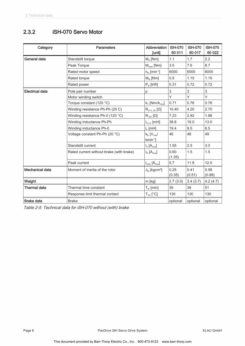
2.3.2 iSH-070 Servo Motor
Category Parameters Abbreviation[unit]
iSH-070 60 011
iSH-070 60 017
iSH-070 60 022
General data Standstill torque M0 [Nm] 1.1 1.7 2.2Peak Torque Mmax [Nm] 3.5 7.6 8.7Rated motor speed nN [min-1] 6000 6000 6000Rated torque MN [Nm] 0.5 1.15 1.15Rated power PN [kW] 0.31 0.72 0.72
Electrical data Pole pair number p 3 3 3Motor winding switch Y Y YTorque constant (120 °C) kT [Nm/Arms] 0.71 0.76 0.76Winding resistance Ph-Ph (20 C) RU-V, 20 [Ω] 10.40 4.20 2.70Winding resistance Ph-0 (120 °C) R120 [Ω] 7.23 2.92 1.88Winding inductance Ph-Ph LU-V [mH] 38.8 19.0 13.0Winding inductance Ph-0 L [mH] 19.4 9.5 6.5Voltage constant Ph-Ph (20 °C) kE [Vrms/
kmin-1]46 48 49
Standstill current I0 [Arms] 1.55 2.5 3.0Rated current without brake (with brake) IN [Arms] 0.60
(1.35)1.5 1.5
Peak current Imax [Arms] 5.7 11.8 12.0
Mechanical data Moment of inertia of the rotor JM [kgcm²] 0.25(0.35)
0.41(0.51)
0.58(0.88)
Weight m [kg] 2.7 (3.0) 3.4 (3.7) 4.2 (4.7)Thermal data Thermal time constant Tth [min] 35 38 51
Response limit thermal contact TTK [°C] 130 130 130
Brake data Brake optional optional optional
Table 2-5: Technical data for iSH-070 without (with) brake
2 Technical data
Page 8 PacDrive iSH Servo Drive System ELAU GmbH
This document provided by Barr-Thorp Electric Co., Inc. 800-473-9123 www.barr-thorp.com
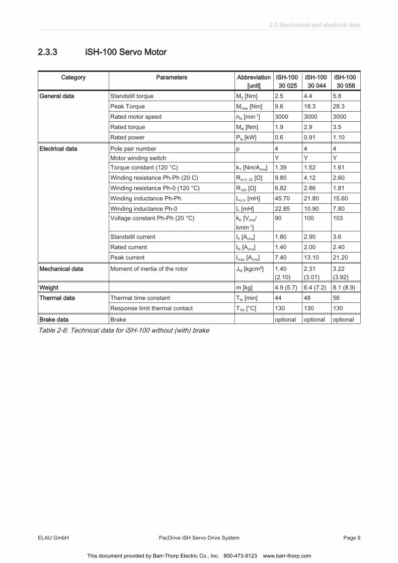
2.3.3 iSH-100 Servo Motor
Category Parameters Abbreviation[unit]
iSH-100 30 025
iSH-100 30 044
iSH-100 30 058
General data Standstill torque M0 [Nm] 2.5 4.4 5.8Peak Torque Mmax [Nm] 9.6 18.3 28.3Rated motor speed nN [min-1] 3000 3000 3000Rated torque MN [Nm] 1.9 2.9 3.5Rated power PN [kW] 0.6 0.91 1.10
Electrical data Pole pair number p 4 4 4Motor winding switch Y Y YTorque constant (120 °C) kT [Nm/Arms] 1.39 1.52 1.61Winding resistance Ph-Ph (20 C) RU-V, 20 [Ω] 9.80 4.12 2.60Winding resistance Ph-0 (120 °C) R120 [Ω] 6.82 2.86 1.81Winding inductance Ph-Ph LU-V [mH] 45.70 21.80 15.60Winding inductance Ph-0 L [mH] 22.85 10.90 7.80Voltage constant Ph-Ph (20 °C) kE [Vrms/
kmin-1]90 100 103
Standstill current I0 [Arms] 1.80 2.90 3.6Rated current IN [Arms] 1.40 2.00 2.40Peak current Imax [Arms] 7.40 13.10 21.20
Mechanical data Moment of inertia of the rotor JM [kgcm²] 1.40(2.10)
2.31(3.01)
3.22(3.92)
Weight m [kg] 4.9 (5.7) 6.4 (7.2) 8.1 (8.9)Thermal data Thermal time constant Tth [min] 44 48 56
Response limit thermal contact TTK [°C] 130 130 130
Brake data Brake optional optional optional
Table 2-6: Technical data for iSH-100 without (with) brake
2.3 Mechanical and electrical data
ELAU GmbH PacDrive iSH Servo Drive System Page 9
This document provided by Barr-Thorp Electric Co., Inc. 800-473-9123 www.barr-thorp.com

2.3.4 iSH-140 Servo Motor
Category Parameters Abbreviation[unit]
iSH-140 30 075
iSH-140 15 085
iSH-140 20 125
General data Standstill torque M0 [Nm] 7.5 8.5 12.5Peak Torque Mmax [Nm] 27.0 27.0 55.0Rated motor speed nN [min-1] 3000 1500 2000Rated torque MN [Nm] 4.6 8.3 9.1Rated power PN [kW] 1.45 1.30 1.91
Electrical data Pole pair number p 5 5 5Motor winding switch Y Y YTorque constant (120 °C) kT [Nm/Arms] 1.60 2.65 2.60Winding resistance Ph-Ph (20 C) RU-V, 20 [Ω] 1.81 4.58 1.90Winding resistance Ph-0 (120 °C) R120 [Ω] 1.26 3.18 1.32Winding inductance Ph-Ph LU-V [mH] 19.10 50.0 22.0Winding inductance Ph-0 L [mH] 9.55 25.0 11.0Voltage constant Ph-Ph (20 °C) kE [Vrms/
kmin-1]108 175 173
Standstill current I0 [Arms] 4.70 3.20 4.8Rated current IN [Arms] 2.90 3.15 3.7Peak current Imax [Arms] 18.8 14.6 24.0
Mechanical data Moment of inertia of the rotor JM [kgcm²] 7.41 7.41 12.68
Weight (with brake) m [kg] 12.5(13.8)
12.5(13.8)
17.2(18.5)
Thermal data Thermal time constant Tth [min] 64 64 74Response limit thermal contact TTK [°C] 130 130 130
Brake data Brake optional optional optional
Table 2-7: Technical data for iSH-140 without (with) brake
2 Technical data
Page 10 PacDrive iSH Servo Drive System ELAU GmbH
This document provided by Barr-Thorp Electric Co., Inc. 800-473-9123 www.barr-thorp.com
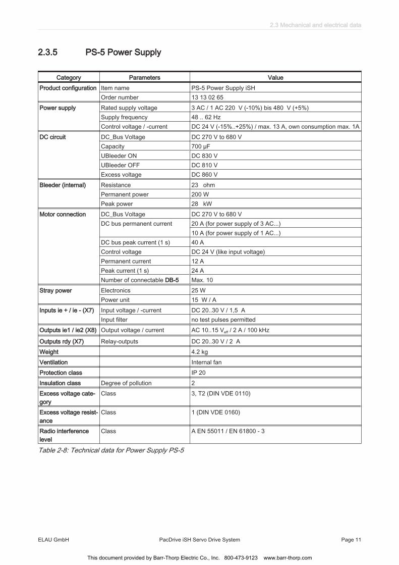
2.3.5 PS-5 Power Supply
Category Parameters ValueProduct configuration Item name PS-5 Power Supply iSH
Order number 13 13 02 65Power supply Rated supply voltage 3 AC / 1 AC 220 V (-10%) bis 480 V (+5%)
Supply frequency 48 .. 62 HzControl voltage / -current DC 24 V (-15%..+25%) / max. 13 A, own consumption max. 1A
DC circuit DC_Bus Voltage DC 270 V to 680 VCapacity 700 µFUBleeder ON DC 830 VUBleeder OFF DC 810 VExcess voltage DC 860 V
Bleeder (internal) Resistance 23 ohmPermanent power 200 W Peak power 28 kW
Motor connection DC_Bus Voltage DC 270 V to 680 VDC bus permanent current 20 A (for power supply of 3 AC...)
10 A (for power supply of 1 AC...)DC bus peak current (1 s) 40 A Control voltage DC 24 V (like input voltage)Permanent current 12 A Peak current (1 s) 24 A Number of connectable DB-5 Max. 10
Stray power Electronics 25 W Power unit 15 W / A
Inputs ie + / ie - (X7) Input voltage / -current DC 20..30 V / 1,5 AInput filter no test pulses permitted
Outputs ie1 / ie2 (X8) Output voltage / current AC 10..15 Veff / 2 A / 100 kHz
Outputs rdy (X7) Relay-outputs DC 20..30 V / 2 AWeight 4.2 kgVentilation Internal fanProtection class IP 20Insulation class Degree of pollution 2Excess voltage cate‐gory
Class 3, T2 (DIN VDE 0110)
Excess voltage resist‐ance
Class 1 (DIN VDE 0160)
Radio interferencelevel
Class A EN 55011 / EN 61800 - 3
Table 2-8: Technical data for Power Supply PS-5
2.3 Mechanical and electrical data
ELAU GmbH PacDrive iSH Servo Drive System Page 11
This document provided by Barr-Thorp Electric Co., Inc. 800-473-9123 www.barr-thorp.com

2.3.6 DB-5 Distribution Box
Category Parameters ValueProduct configuration Item name Distribution Box DB-5 iSH
Order number 13 13 02 66 - 001Power supply DC bus voltage / DC bus current DC 270 V to 680 V / 20 A
Control voltage / -current DC 24 V (-15%..+25%) / max 12 AControl voltage with brakes DC 24 V (-10%..+6%)
Weight 0.85 kgMaterial Polycarbonate [Lexan 940A]Ventilation Natural convectionProtection class IP 65Isolation class Degree of pollution 2Excess voltage cate‐gory
Class 3, T2 (DIN VDE 0110)
Excess voltage resist‐ance
Class 1 (DIN VDE 0160)
Radio interferencelevel
Class A EN 55011 / EN 61800 - 3
Table 2-9: Technical data for Distribution Box DB-5
2 Technical data
Page 12 PacDrive iSH Servo Drive System ELAU GmbH
This document provided by Barr-Thorp Electric Co., Inc. 800-473-9123 www.barr-thorp.com

2.3.7 Encoder
SinCos® (SKS36) single turn
Parameters Value UnitNumber of revolutions 1Number of sine/cosine periods 128 Per revolutionAbsolute measuring range 1 RevolutionError limits of the digital absolute value +/-5.3 Angular minutesError limits when evaluating the 128 signals (integral non-linearity)
+/-1.3 Angular minutes
Signal form Sine
Table 2-10: Technical data of the SinCos encoder (SKS-36)
SinCos® (SKM36) multiturn
Parameters Value UnitNumber of revolutions 4096Number of sine/cosine periods 128 Per revolutionAbsolute measuring range 1 RevolutionError limits of the digital absolute value +/-5.3 Angular minutesError limits when evaluating the 128 signals (integral non-linearity)
+/-1.3 Angular minutes
Signal form Sine
Table 2-11: Technical data of the SinCos® encoder (SKM-36)
2.3 Mechanical and electrical data
ELAU GmbH PacDrive iSH Servo Drive System Page 13
This document provided by Barr-Thorp Electric Co., Inc. 800-473-9123 www.barr-thorp.com

2.4 Electrical connections
TM
2
1
Figure 2-1: iSH connection overview
1 Connector2 Additional ground connection
Pin Designation Meaning1 PE Ground conductor2 DC- DC circuit -3 DC + DC circuit +4 0 V Control voltage5 24 V Control voltage6 SERC_OUT + SERCOS output7 SERC_OUT - SERCOS output8 ie1 Inverter Enable9 ie2 Inverter Enable10 SERC_OUT_S SERCOS shield11 SERC_IN_S SERCOS shield12 - not connected13 - not connected14 SERC_IN + SERCOS input15 SERC_IN - SERCOS input
Table 2-12: Connector iSH
2 Technical data
Page 14 PacDrive iSH Servo Drive System ELAU GmbH
This document provided by Barr-Thorp Electric Co., Inc. 800-473-9123 www.barr-thorp.com
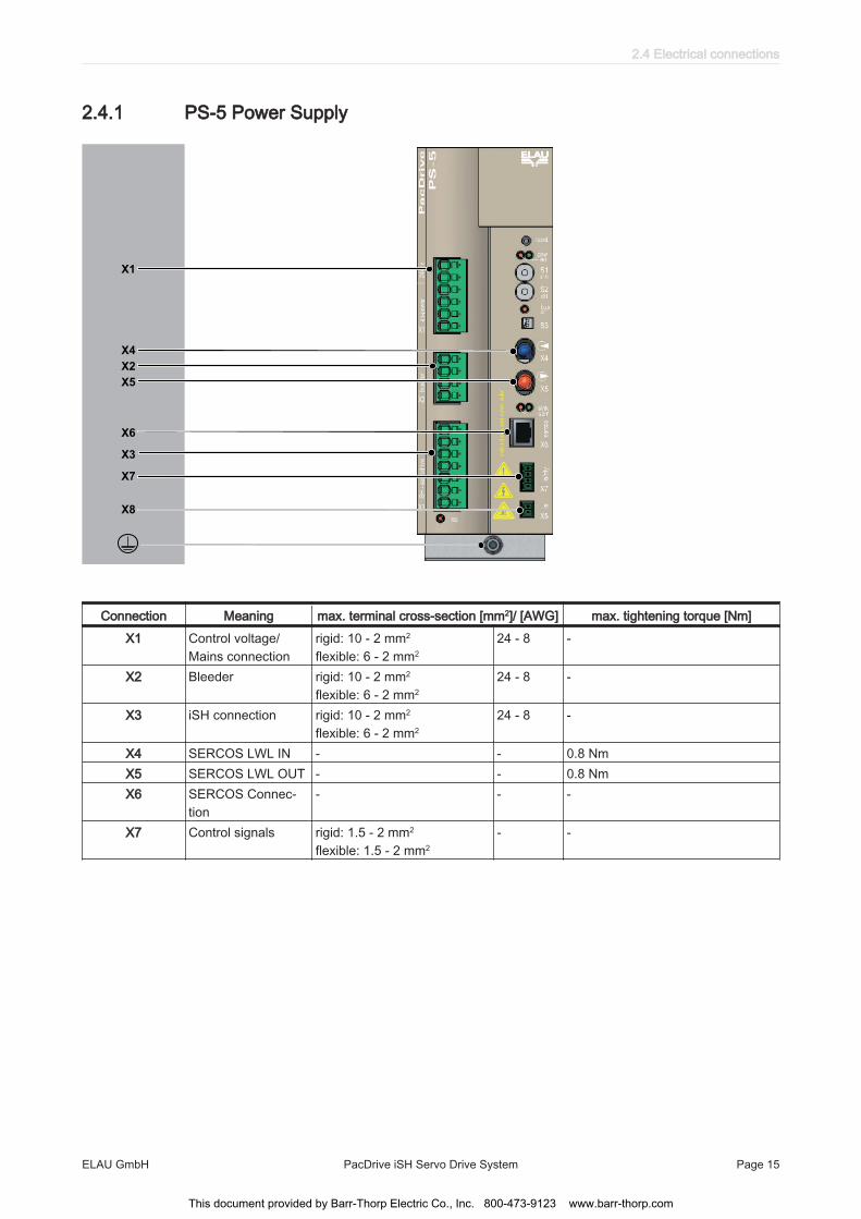
2.4.1 PS-5 Power Supply
TM
X1
X4
X2
X5
X6
X3
X7
X8
Connection Meaning max. terminal cross-section [mm2]/ [AWG] max. tightening torque [Nm]X1 Control voltage/
Mains connectionrigid: 10 - 2 mm2
flexible: 6 - 2 mm224 - 8 -
X2 Bleeder rigid: 10 - 2 mm2
flexible: 6 - 2 mm224 - 8 -
X3 iSH connection rigid: 10 - 2 mm2
flexible: 6 - 2 mm224 - 8 -
X4 SERCOS LWL IN - - 0.8 NmX5 SERCOS LWL OUT - - 0.8 NmX6 SERCOS Connec‐
tion- - -
X7 Control signals rigid: 1.5 - 2 mm2
flexible: 1.5 - 2 mm2- -
2.4 Electrical connections
ELAU GmbH PacDrive iSH Servo Drive System Page 15
This document provided by Barr-Thorp Electric Co., Inc. 800-473-9123 www.barr-thorp.com
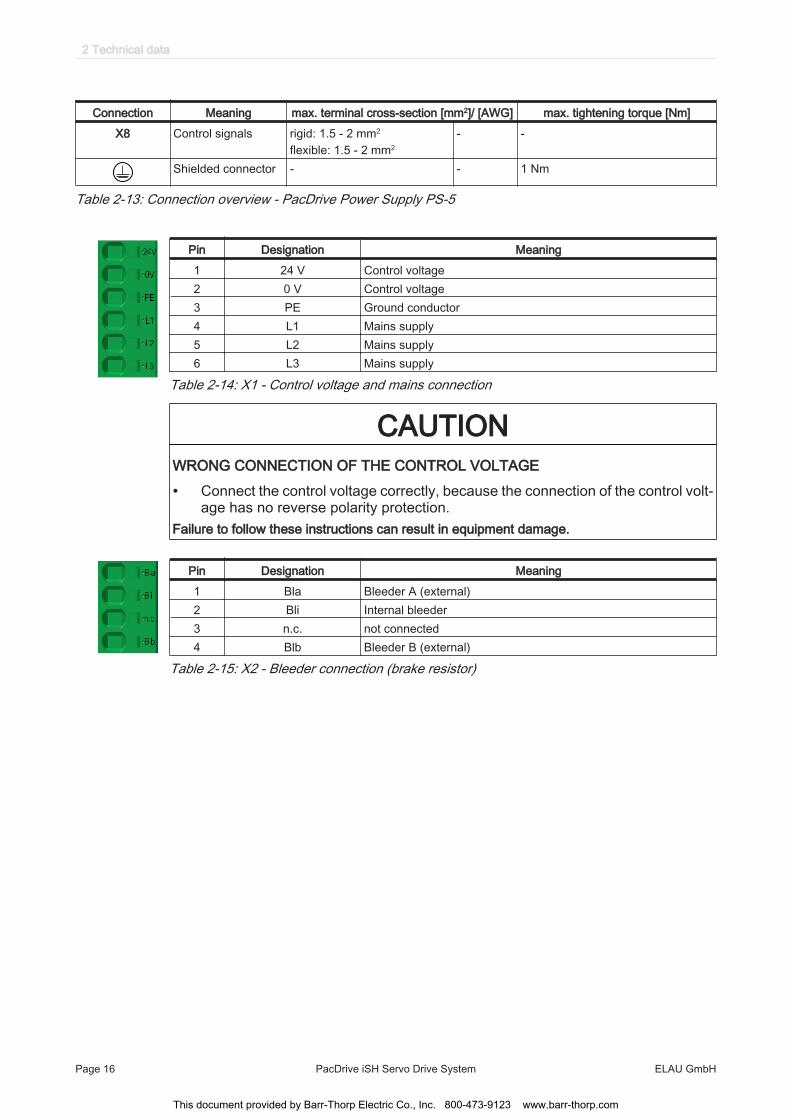
Connection Meaning max. terminal cross-section [mm2]/ [AWG] max. tightening torque [Nm]X8 Control signals rigid: 1.5 - 2 mm2
flexible: 1.5 - 2 mm2- -
Shielded connector - - 1 Nm
Table 2-13: Connection overview - PacDrive Power Supply PS-5
Pin Designation Meaning1 24 V Control voltage2 0 V Control voltage3 PE Ground conductor4 L1 Mains supply5 L2 Mains supply6 L3 Mains supply
Table 2-14: X1 - Control voltage and mains connection
CAUTIONWRONG CONNECTION OF THE CONTROL VOLTAGE
• Connect the control voltage correctly, because the connection of the control volt‐age has no reverse polarity protection.
Failure to follow these instructions can result in equipment damage.
Pin Designation Meaning1 Bla Bleeder A (external)2 Bli Internal bleeder3 n.c. not connected4 Blb Bleeder B (external)
Table 2-15: X2 - Bleeder connection (brake resistor)
2 Technical data
Page 16 PacDrive iSH Servo Drive System ELAU GmbH
This document provided by Barr-Thorp Electric Co., Inc. 800-473-9123 www.barr-thorp.com
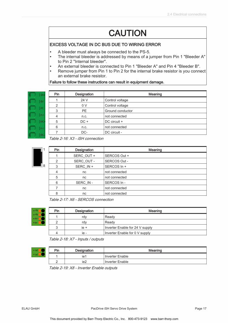
CAUTIONEXCESS VOLTAGE IN DC BUS DUE TO WIRING ERROR
• A bleeder must always be connected to the PS-5.• The internal bleeder is addressed by means of a jumper from Pin 1 "Bleeder A"
to Pin 2 "Internal bleeder".• An external bleeder is connected to Pin 1 "Bleeder A" and Pin 4 "Bleeder B".• Remove jumper from Pin 1 to Pin 2 for the internal brake resistor is you connect
an external brake resistor.Failure to follow these instructions can result in equipment damage.
Pin Designation Meaning1 24 V Control voltage2 0 V Control voltage3 PE Ground conductor4 n.c. not connected5 DC + DC circuit +6 n.c. not connected7 DC- DC circuit -
Table 2-16: X3 - iSH connection
1
8
Pin Designation Meaning1 SERC_OUT + SERCOS Out +2 SERC_OUT - SERCOS Out -3 SERC_IN + SERCOS In +4 nc not connected5 nc not connected6 SERC_IN - SERCOS In -7 nc not connected8 nc not connected
Table 2-17: X6 - SERCOS connection
Pin Designation Meaning1 rdy Ready2 rdy Ready3 ie + Inverter Enable for 24 V supply4 ie - Inverter Enable for 0 V supply
Table 2-18: X7 - Inputs / outputs
Pin Designation Meaning1 ie1 Inverter Enable2 ie2 Inverter Enable
Table 2-19: X8 - Inverter Enable outputs
2.4 Electrical connections
ELAU GmbH PacDrive iSH Servo Drive System Page 17
This document provided by Barr-Thorp Electric Co., Inc. 800-473-9123 www.barr-thorp.com

CAUTIONWRONG WIRING OF THE INVERTER ENABLE OUTPUTS
• Check if the Inverter Enable outputs are short circuit proof.Failure to follow these instructions can result in equipment damage.
CAUTIONWIRING ERROR
• Only connect the ie1/ie2 signal of the hybrid cable to the AC voltage ie1/ie2 onPS-5 connector X8.
Failure to follow these instructions can result in equipment damage.
2.4.2 DB-5 Distribution Box
TM
X1
X2
X3
X4
X5
2 Technical data
Page 18 PacDrive iSH Servo Drive System ELAU GmbH
This document provided by Barr-Thorp Electric Co., Inc. 800-473-9123 www.barr-thorp.com
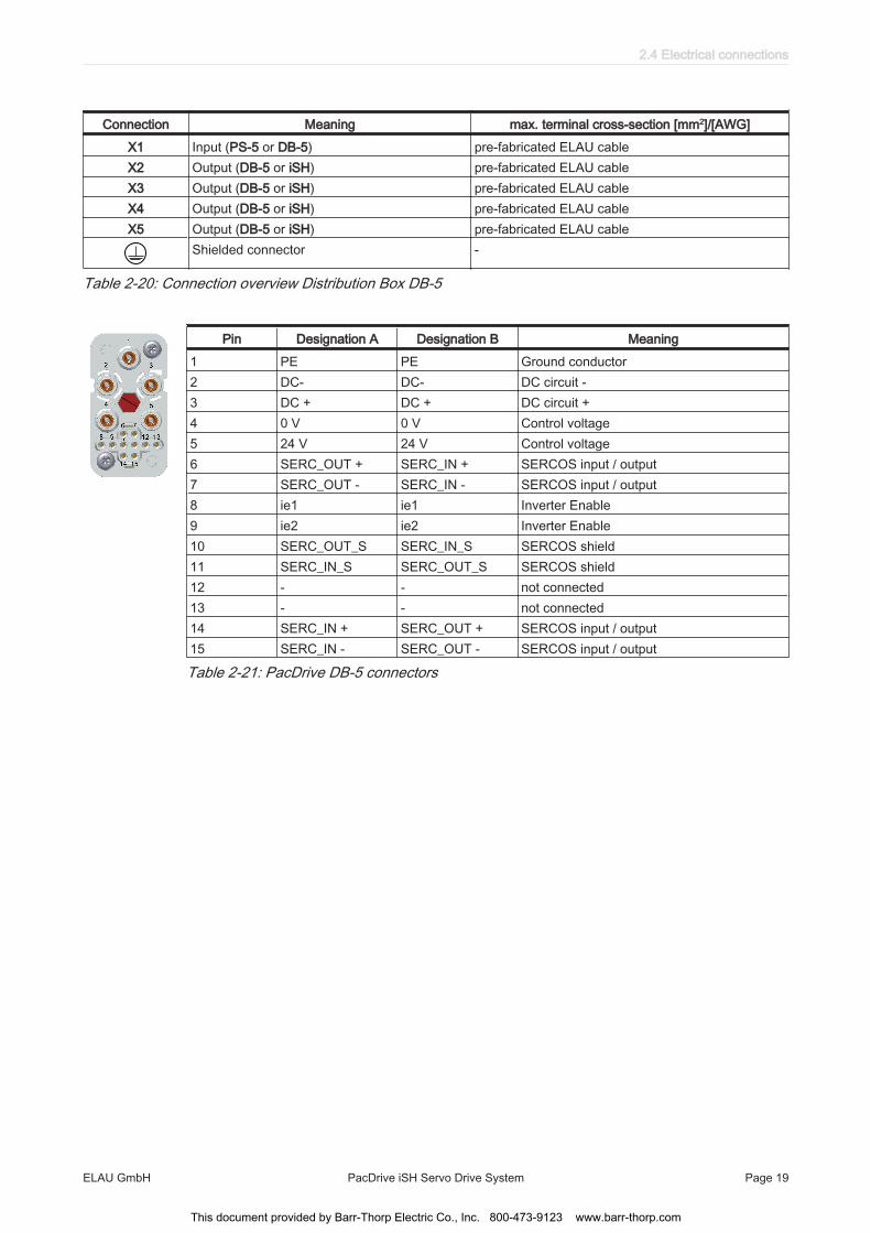
Connection Meaning max. terminal cross-section [mm2]/[AWG]X1 Input (PS-5 or DB-5) pre-fabricated ELAU cableX2 Output (DB-5 or iSH) pre-fabricated ELAU cableX3 Output (DB-5 or iSH) pre-fabricated ELAU cableX4 Output (DB-5 or iSH) pre-fabricated ELAU cableX5 Output (DB-5 or iSH) pre-fabricated ELAU cable
Shielded connector -
Table 2-20: Connection overview Distribution Box DB-5
Pin Designation A Designation B Meaning1 PE PE Ground conductor2 DC- DC- DC circuit -3 DC + DC + DC circuit +4 0 V 0 V Control voltage5 24 V 24 V Control voltage6 SERC_OUT + SERC_IN + SERCOS input / output7 SERC_OUT - SERC_IN - SERCOS input / output8 ie1 ie1 Inverter Enable9 ie2 ie2 Inverter Enable10 SERC_OUT_S SERC_IN_S SERCOS shield11 SERC_IN_S SERC_OUT_S SERCOS shield12 - - not connected13 - - not connected14 SERC_IN + SERC_OUT + SERCOS input / output15 SERC_IN - SERC_OUT - SERCOS input / output
Table 2-21: PacDrive DB-5 connectors
2.4 Electrical connections
ELAU GmbH PacDrive iSH Servo Drive System Page 19
This document provided by Barr-Thorp Electric Co., Inc. 800-473-9123 www.barr-thorp.com

2.5 Dimensions
Dimensions (iSH-070)
B
70
2,5
8,5
L 187
M4
69
Ø C
Ø 6
0 j6
B K
A
34
73
10
7
35
LL Ø
5,5
x3,5
(4x)
TK Ø 75
TK Ø 82
20-35mm, see connector! K
26
12
7
without Option-module
with Option-module
68
Figure 2-2: Dimension diagram for iSH-070 motor
Please note that the iSH series 070 uses different shaft diameters. The shaft diameterfor the iSH070 60 022 is 14 mm.
Dimensions table
Dimensions iSH070 60 011 iSH070 60 017 iSH070 60 022A (with brake) 175 (182) 189 (215) 222 (256)B 23 23 30C 11 k6 11 k6 14 k6K (with brake) 212 (219) 226 (252) 259 (293)L (with brake) 25 (31) 38 (64) 71 (105)
Table 2-22: Dimensions of the iSH 070 (dimension specifications in mm)
2 Technical data
Page 20 PacDrive iSH Servo Drive System ELAU GmbH
This document provided by Barr-Thorp Electric Co., Inc. 800-473-9123 www.barr-thorp.com
Dimensions (iSH-100)
70
100
M4
187
14
13
7
99
Ø9
5 j6 Ø
C
3,5
B K
A
34
10
3
L5
0
98
Ø 9
(4x)
TK Ø 115
20-35mm, see connector!
K
15
7
26
without Option-module
with Option-module
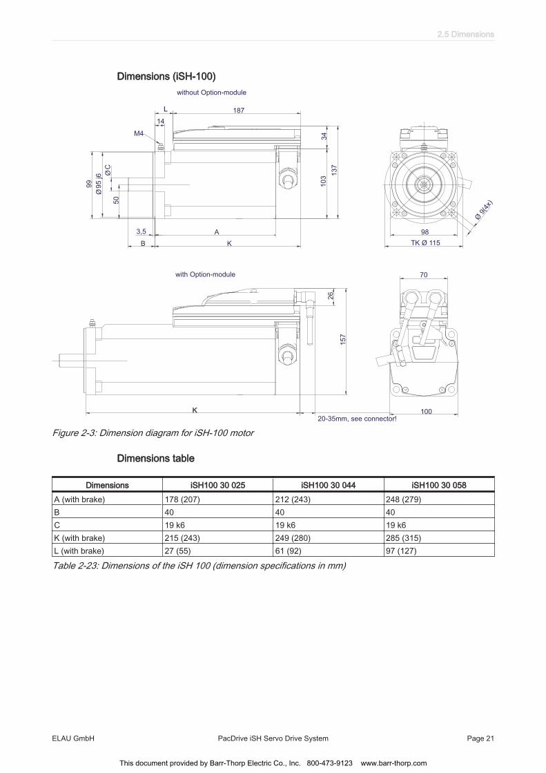
Figure 2-3: Dimension diagram for iSH-100 motor
Dimensions table
Dimensions iSH100 30 025 iSH100 30 044 iSH100 30 058A (with brake) 178 (207) 212 (243) 248 (279)B 40 40 40C 19 k6 19 k6 19 k6K (with brake) 215 (243) 249 (280) 285 (315)L (with brake) 27 (55) 61 (92) 97 (127)
Table 2-23: Dimensions of the iSH 100 (dimension specifications in mm)
2.5 Dimensions
ELAU GmbH PacDrive iSH Servo Drive System Page 21
This document provided by Barr-Thorp Electric Co., Inc. 800-473-9123 www.barr-thorp.com
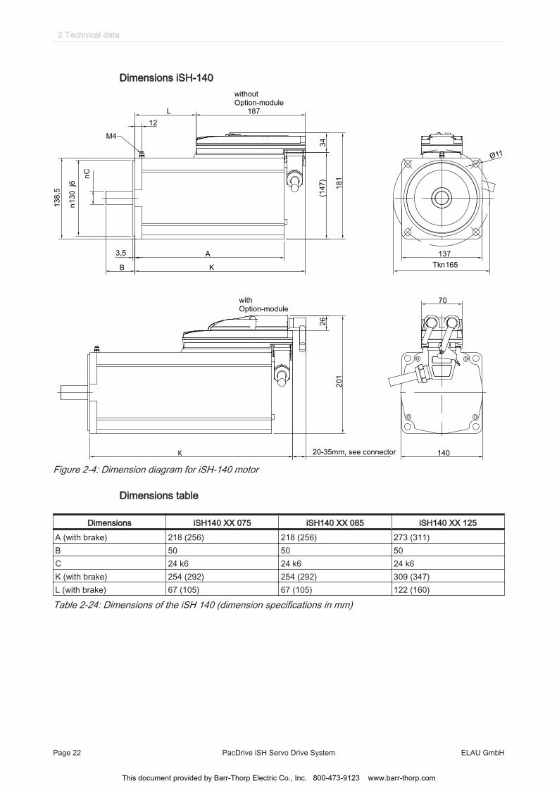
Dimensions iSH-140
137
Tkn165
70
140
187 L
12
M4
n
C
3,5 A
B K
18
1
34
(1
47
)
without Option-module
with Option-module
K
26
20
1
20-35mm, see connector
n1
30
j6
13
8,5
Ø11
Figure 2-4: Dimension diagram for iSH-140 motor
Dimensions table
Dimensions iSH140 XX 075 iSH140 XX 085 iSH140 XX 125A (with brake) 218 (256) 218 (256) 273 (311)B 50 50 50C 24 k6 24 k6 24 k6K (with brake) 254 (292) 254 (292) 309 (347)L (with brake) 67 (105) 67 (105) 122 (160)
Table 2-24: Dimensions of the iSH 140 (dimension specifications in mm)
2 Technical data
Page 22 PacDrive iSH Servo Drive System ELAU GmbH
This document provided by Barr-Thorp Electric Co., Inc. 800-473-9123 www.barr-thorp.com
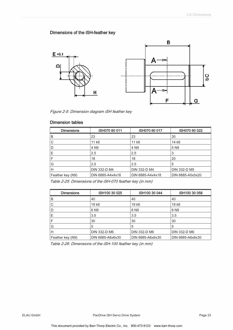
Dimensions of the iSH-feather key
Figure 2-5: Dimension diagram iSH feather key
Dimension tables
Dimensions iSH070 60 011 iSH070 60 017 iSH070 60 022B 23 23 30C 11 k6 11 k6 14 k6D 4 N9 4 N9 5 N9E 2.5 2.5 3F 18 18 20G 2.5 2.5 5H DIN 332-D M4 DIN 332-D M4 DIN 332-D M5Feather key (N9) DIN 6885-A4x4x18 DIN 6885-A4x4x18 DIN 6885-A5x5x20
Table 2-25: Dimensions of the iSH-070 feather key (in mm)
Dimensions iSH100 30 025 iSH100 30 044 iSH100 30 058B 40 40 40C 19 k6 19 k6 19 k6D 6 N9 6 N9 6 N9E 3.5 3.5 3.5F 30 30 30G 5 5 5H DIN 332-D M6 DIN 332-D M6 DIN 332-D M6Feather key (N9) DIN 6885-A6x6x30 DIN 6885-A6x6x30 DIN 6885-A6x6x30
Table 2-26: Dimensions of the iSH-100 feather key (in mm)
2.5 Dimensions
ELAU GmbH PacDrive iSH Servo Drive System Page 23
This document provided by Barr-Thorp Electric Co., Inc. 800-473-9123 www.barr-thorp.com

Dimensions Power Supply PS-5
251
88
35
24
3,5
3524
7
242,50
285,4
Ø3,5
Ø6,5
15
8
Figure 2-6: Dimension diagram Power Supply PS-5
2 Technical data
Page 24 PacDrive iSH Servo Drive System ELAU GmbH
This document provided by Barr-Thorp Electric Co., Inc. 800-473-9123 www.barr-thorp.com

Dimensions Distribution Box DB-5
230,00
215,00R7
135,00
151,40
120,00
70,30
56,00
26,10
67,80
94,0
56,0
67,8
Figure 2-7: Dimension diagram Distribution Box DB-5
2.5 Dimensions
ELAU GmbH PacDrive iSH Servo Drive System Page 25
This document provided by Barr-Thorp Electric Co., Inc. 800-473-9123 www.barr-thorp.com

3 Type code
Flange Size
070, 100
Rating Speed x 100 min-1
(30)
Standstill torque /10 Nm
(e.g. 011, 017, 022, 025, 044, 058)
Voltage
0 = DC 560V / integr. servo electronic
Shaft end
0 = Smooth shaft
1 = Keyed shaft according to DIN 6885
3 = Smooth shaft, stainless steel
4 = Keyed shaft, stainless stell according to DIN 6885
Surface
0 = Standard coating
Cooling
0 = Self-cooling
Connection system
0 = Hybrid connector
Sealing (Protection class) Shaft
0x = Without shaft sealing
(IP54 excl. IM V3: IP40)
1x = Shaft sealing (IP65)
Sealing (Protection class) Housing
x0 = Standard IP65
Encoder
0 = SinCos SKS 36
1 = SinCos SKM 36
Brake
0 = Without holding brake
1 = With holding brake
Options
00 = Without option
01 = iSH-DIS1 connected
Flange Size
Rating Speed
Standstill torque
Voltage/Electronic
Shaft end
Surface
Cooling
Connection system
Sealing (Protection Class)Shaft / Housing
Encoder
Brake
Options
iSH070/60017/0 /0 /00 /0 /00 /00 /00
3 Type code
Page 26 PacDrive iSH Servo Drive System ELAU GmbH
This document provided by Barr-Thorp Electric Co., Inc. 800-473-9123 www.barr-thorp.com

4 Optional module iSH-DIO8Features:
• 8 bidirectional floating inputs/outputs (configurable in the PLC configuration)• Connection via two M12 connectors (8-pin), each with 4 inputs/outputs• Floating internal power supply of outputs up to 0.1 A total current for 8 inputs/
outputs• Maximum 2 A total output current via 8 outputs when using external supply voltage• 0.5 A output current max. per output when using external supply• Short-circuit detection and open-circuit detection on outputs• Two inputs with special functions (touch probe, counter)
Figure 4-1: Connecting the DIO-4 M12 distributor to the iSH-DIO8 optional module
4.5 Dimensions
ELAU GmbH PacDrive iSH Servo Drive System Page 27
This document provided by Barr-Thorp Electric Co., Inc. 800-473-9123 www.barr-thorp.com

4.1 Technical data
Parameters ValueItem name iSH-DIO8 I/O moduleOrder number 13 13 02 67iSH-DIO8 supply - Control voltage / control current DC 24 V (-15% / +20%)
when using internal I/O supply: max. 300 mAwhen using external I/O supply: max. 80 mA
digital inputs - Number- Voltage in UIN 0 range- Voltage in UIN 1 range - Input current- Electrical isolation- Protected against reverse polarity- Input filter
8 (IEC61131-2 Type I)DC -3 ... 5 VDC 15 ... 30 VIIN = 2 mA at UIN = 15 V500 V floating opposite PEYes 1 or 5 ms, configurable
digital outputs - Number- Output voltage- Ratedcurrent per output- Total module current across all8 inputs/outputs- Activation current- Leakage cur‐rent 0 signal- Transmission time- Short-circuitproof- Supply output- Electrical isolation
8 (IEC61131-2) (+UL-3 V) < UOUT < +UL
Ie = 500 mAWhen using internal I/O supply: 0.1 A When using external I/O supply: 2.0 A Iemax > 2 A for 1 s< 0.4 mA100 µsYesDC 24 V (-15% / +20%) / 2 A500 V floating opposite PE
Weight 0,22 kg Ambient conditions - Protection class- Ambient temp. during operation- During storage and transport- Excess voltage category
- Degree of radio interference
IP 65+5...+40 °C-25...+70 °C, Temperature fluctuation tmax =30 K/h
Class A EN55011 / EN61800-3Approval CE, cULus
Table 4-1: Technical data for iSH-DIO8
4 Optional module iSH-DIO8
Page 28 PacDrive iSH Servo Drive System ELAU GmbH
This document provided by Barr-Thorp Electric Co., Inc. 800-473-9123 www.barr-thorp.com
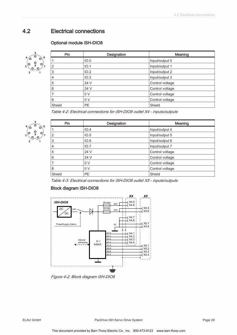
4.2 Electrical connections
Optional module iSH-DIO8
Pin Designation Meaning1 IO.0 Input/output 02 IO.1 Input/output 13 IO.2 Input/output 24 IO.3 Input/output 35 24 V Control voltage6 24 V Control voltage7 0 V Control voltage8 0 V Control voltageShield PE Shield
Table 4-2: Electrical connections for iSH-DIO8 outlet X4 - inputs/outputs
Pin Designation Meaning1 IO.4 Input/output 42 IO.5 Input/output 53 IO.6 Input/output 64 IO.7 Input/output 75 24 V Control voltage6 24 V Control voltage7 0 V Control voltage8 0 V Control voltageShield PE Shield
Table 4-3: Electrical connections for iSH-DIO8 outlet X5 - inputs/outputs
Block diagram iSH-DIO8
in -/ output
DC
DC
PowerSupply (intern)
24V
internal adressing
X4.5 X4.6
X5.5 X5.6
X4.7 X4.8
X5.7 X5.8
X4.1 X4.2 X4.3 X4.4
X5.1 X5.2 X5.3 X5.4
2A max. 24V
24V
0V
IO.0
IO.1
IO.2
IO.3
IO.4
IO.5
IO.6
IO.7
2A max.
iSH-DIO8
X4 X5
Figure 4-2: Block diagram iSH-DIO8
4.2 Electrical connections
ELAU GmbH PacDrive iSH Servo Drive System Page 29
This document provided by Barr-Thorp Electric Co., Inc. 800-473-9123 www.barr-thorp.com

DIO-4 M12 distributor
outlet *) 3 4 outlet *)
outlet *) 1 2 outlet *)
*) locking torque 0,6 ... 0,7 Nm
Figure 4-3: Connection scheme M12 distributor DIO-4
Pin Designation Meaning1 24 V Control voltage2 free Reserved3 0 V Control voltage4 IO.x Input/output x (X4: 0 ... 3 or X5: 4 ... 7)5 PE Shield
Table 4-4: Electrical connections for DIO-4 outlet 1 ... 4 - Inputs/Outputs
CAUTIONTHERE IS NO POTENTIAL ISOLATION AMONG ANY OF THE 8 INPUTS/OUT‐PUTS.
• When using an external power supply, you must protect it with 2 A (time-lag).• The control voltage when using external I/O supply can be supplied either via the
X4, X5 outlets or via the DIO-4 M12 distributor.
1
2
3
4
5 1
2
3
4
5 1
2
3
4
5 1
2
3
4
5
PE -1 -2 +1 +2 1 2 3 4
shield blue red grey pink white brown green yellow
outlet 1 outlet 2 outlet 3 outlet 4
Figure 4-4: Block diagram DIO-4
4 Optional module iSH-DIO8
Page 30 PacDrive iSH Servo Drive System ELAU GmbH
This document provided by Barr-Thorp Electric Co., Inc. 800-473-9123 www.barr-thorp.com
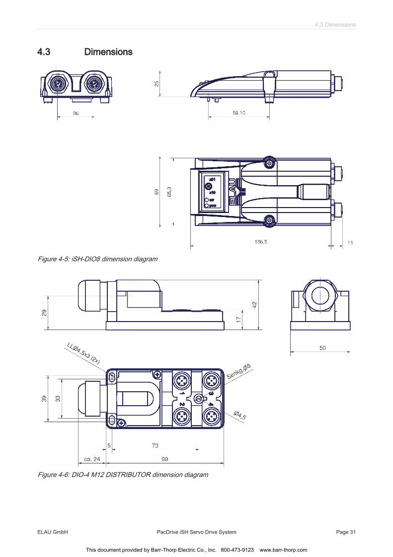
4.3 Dimensions
Figure 4-5: iSH-DIO8 dimension diagram
Figure 4-6: DIO-4 M12 DISTRIBUTOR dimension diagram
4.3 Dimensions
ELAU GmbH PacDrive iSH Servo Drive System Page 31
This document provided by Barr-Thorp Electric Co., Inc. 800-473-9123 www.barr-thorp.com
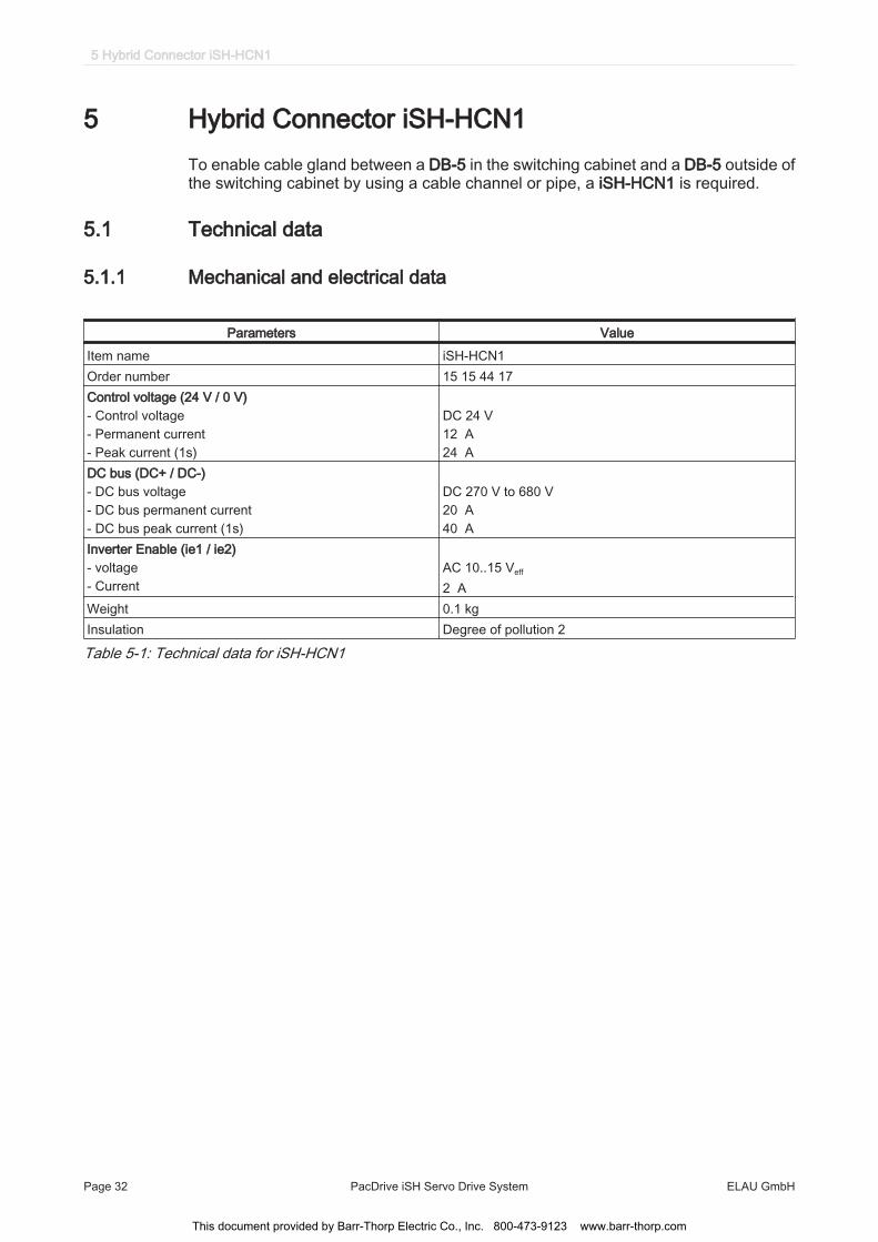
5 Hybrid Connector iSH-HCN1To enable cable gland between a DB-5 in the switching cabinet and a DB-5 outside ofthe switching cabinet by using a cable channel or pipe, a iSH-HCN1 is required.
5.1 Technical data
5.1.1 Mechanical and electrical data
Parameters ValueItem name iSH-HCN1Order number 15 15 44 17Control voltage (24 V / 0 V) - Control voltage- Permanent current - Peak current (1s)
DC 24 V12 A24 A
DC bus (DC+ / DC-) - DC bus voltage - DC bus permanent current - DC bus peak current (1s)
DC 270 V to 680 V20 A40 A
Inverter Enable (ie1 / ie2) - voltage - Current
AC 10..15 Veff 2 A
Weight 0.1 kgInsulation Degree of pollution 2
Table 5-1: Technical data for iSH-HCN1
5 Hybrid Connector iSH-HCN1
Page 32 PacDrive iSH Servo Drive System ELAU GmbH
This document provided by Barr-Thorp Electric Co., Inc. 800-473-9123 www.barr-thorp.com
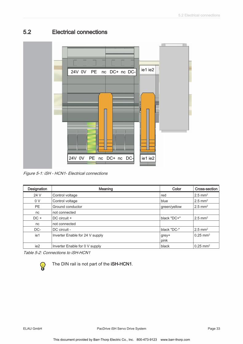
5.2 Electrical connections
TM
ie1 ie2
ie1 ie2
24V 0V PE nc DC+ nc DC-
24V 0V PE nc DC+ nc DC-
Figure 5-1: iSH - HCN1- Electrical connections
Designation Meaning Color Cross-section24 V Control voltage red 2.5 mm2
0 V Control voltage blue 2.5 mm2
PE Ground conductor green/yellow 2.5 mm2
nc not connectedDC + DC circuit + black "DC+" 2.5 mm2
nc not connectedDC- DC circuit - black "DC-" 2.5 mm2
ie1 Inverter Enable for 24 V supply grey+pink
0.25 mm2
ie2 Inverter Enable for 0 V supply black 0.25 mm2
Table 5-2: Connections to iSH-HCN1
The DIN rail is not part of the iSH-HCN1.
5.2 Electrical connections
ELAU GmbH PacDrive iSH Servo Drive System Page 33
This document provided by Barr-Thorp Electric Co., Inc. 800-473-9123 www.barr-thorp.com
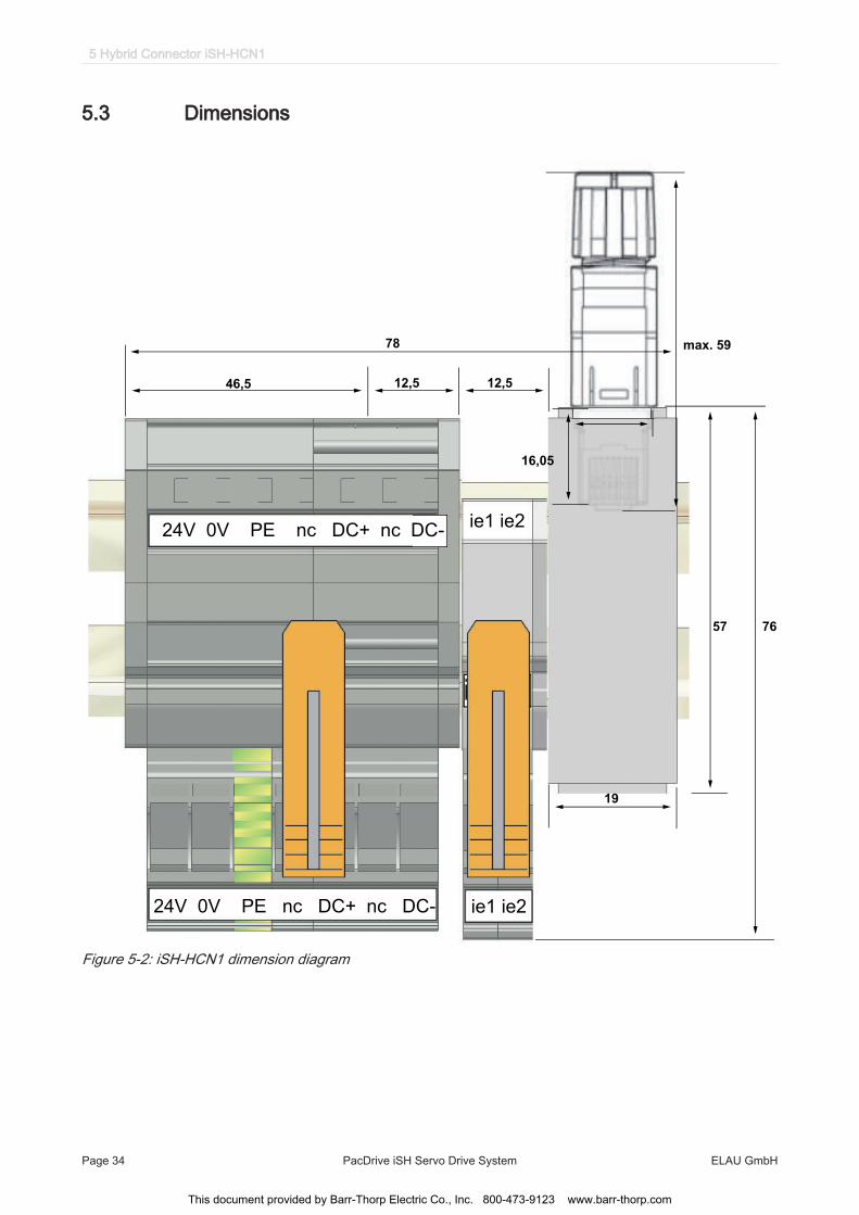
5.3 Dimensions
ie1 ie2
ie1 ie2
24V 0V PE nc DC+ nc DC-
24V 0V PE nc DC+ nc DC-
46,5 12,5 12,5
78
57 76
19
max. 59
16,05
Figure 5-2: iSH-HCN1 dimension diagram
5 Hybrid Connector iSH-HCN1
Page 34 PacDrive iSH Servo Drive System ELAU GmbH
This document provided by Barr-Thorp Electric Co., Inc. 800-473-9123 www.barr-thorp.com