data sheet isys-4001 (rs232) designed isys-4002 (rs485) · 24.195 ghz channel 6 (eu) available from...
TRANSCRIPT

Page
1
DAT
A S
HE
ET
iSYS
-400
1 / i
SYS
-400
2
Vers
ion
2.7
CONFIDENTIAL AND PROPRIETARYThe information contained in this document shall remain the sole and exclusive property of InnoSenT GmbH and shall not be
disclosed by the recipient to third parties without prior consent of InnoSenT in writing.
Experience and Reliability in Radar Technologywww.InnoSenT.de
Data Sheet iSYS-4001 (RS232) iSYS-4002 (RS485) Version 2.7 - 19.07.2016
K-Band Movement Detection System
• Industrial Applications
• Energy Saving
• Traffic Monitoring
• Lighting Control
• Security Applications
Movement Velocity Direction Presence Distance Angle
DESCRIPTION
K-Band based motion detector with intelligent µC decision unit. It can detect moving objects in a speed range of 0.8 km/h (0.48 mph) up to 250 km/h (155.32 mph). The detection range is from 0.3m (1ft) up to 150m (492.5ft) (depending on RCS of moving object). The sensor provides 3 programmable output pins that offers a wide area of individual configurations, to be sure that the sensor fits to your individual requirements. The programming can be easily done by an GUI, that is available under www.innosent.de.
ADDITIONAL INFORMATION
InnoSenT Standard Product. Changes will not be notified as long as there is no influence on form, fit and within this data sheet specified function of the product.
PRODUCT FAMILY
APPLICATIONS
FEATURES: » radar-based motion detector working in the 24GHz - ISM - Band
» Detection of moving objects in a distance from 0.3 to 150m (depending on RCS of detected object)
» Detection range configurable
» Detectable speed: ±0.8km/h up to ±250 km/h
» Direction of motion discrimination
» Protection class IP67 for outdoor use
» Robust metal housing
CERTIFICATES
InnoSenT GmbH has established and applies a quality system for: development, production and sales of radar sensors for industrial and automotive sensors.
RoHS-INFO
This product is compliant to the restriction of hazardous substances (RoHS - European Union directive 2011/65/EU).
and manufactured in Germany
designed
Page
2
DAT
A S
HE
ET
iSYS
-400
1 / i
SYS
-400
2
Vers
ion
2.7
CONFIDENTIAL AND PROPRIETARYThe information contained in this document shall remain the sole and exclusive property of InnoSenT GmbH and shall not be
disclosed by the recipient to third parties without prior consent of InnoSenT in writing.
Experience and Reliability in Radar Technologywww.InnoSenT.de
PARAMETER CONDITIONS SYMBOL MIN TYP MAX UNITS
Radar
transmit frequencies channel 1 (EU) f1 24.190 GHz
channel 2 (EU) f2 24.210 GHz
channel 3 (US) f3 24.115 GHz
channel 4 (US) f4 24.135 GHz
channel 5 (EU) available from firmware v1.310 f5 24.195 GHz
channel 6 (EU) available from firmware v1.310 f6 24.215 GHz
channel 7 (US) available from firmware v1.310 f7 24.120 GHz
channel 8 (US) available from firmware v1.310 f8 24.140 GHz
output power (EIRP) @ 25°C Pout 20 dBm
Sensor
detection distance depending on RCS of detected object dr 150 m
speed range vr 0.8 250 km/h
standard detection field compare with plot on page 3 horizontal 34 °
vertical 49 °
Power supply
supply voltage VCC 10 30 V
supply current @ 12V without digital out current ICC_12V 135 150 mA
supply current @ 24V without digital out current ICC_24V 76 85 mA
Digital Output Current
OUT1 open drain IOut -400 mA
OUT2 open drain IOut -400 mA
OUT3 open drain IOut -400 mA
digital total current IOut -800 mA
Environment
operating temperature TOP -25 +60 °C
storage temperature TSTG -25 +60 °C
Mechanical Outlines
outline dimensions compare to schematic on page 4heightlengthwidth
43.475.640.0
mm
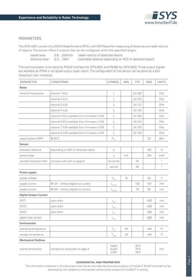
PARAMETERS
The iSYS-4001 consist of a 24GHz Radarfrontend (RFE) with DSP-Board for measuring of distance and radial velocity of objects. The sensor offers 3 outputs that can be configured within the specified ranges:
speed area: 0.8....250km/h (radial velocity of detected object) distance area: 0.3....150m (reachable distance depending on RCS of detected object)
The communication is be done by RS232 interface for iSYS-4001 and RS485 for iSYS-4002. Three output signals are available as PWM or as digital output (open drain). The configuration of the sensor can be done by a GUI (Graphical User Interface).
Page
3
DAT
A S
HE
ET
iSYS
-400
1 / i
SYS
-400
2
Vers
ion
2.7
CONFIDENTIAL AND PROPRIETARYThe information contained in this document shall remain the sole and exclusive property of InnoSenT GmbH and shall not be
disclosed by the recipient to third parties without prior consent of InnoSenT in writing.
Experience and Reliability in Radar Technologywww.InnoSenT.de
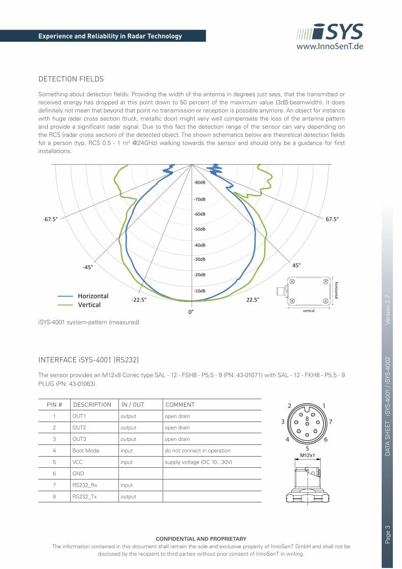
iSYS-4001 system-pattern (measured)
DETECTION FIELDS
Something about detection fields: Providing the width of the antenna in degrees just says, that the transmitted or received energy has dropped at this point down to 50 percent of the maximum value (3dB-beamwidth). It does definitely not mean that beyond that point no transmission or reception is possible anymore. An object for instance with huge radar cross section (truck, metallic door) might very well compensate the loss of the antenna pattern and provide a significant radar signal. Due to this fact the detection range of the sensor can vary depending on the RCS (radar cross section) of the detected object. The shown schematics below are theoretical detection fields for a person (typ. RCS 0.5 - 1 m2 @24GHz) walking towards the sensor and should only be a guidance for first installations.
45°
22.5°-22.5°
0°
-10dB
-20dB
-30dB
-40dB
-50dB
-60dB
-70dB
-80dB
-45°
Vertical
67.5°-67.5°
Horizontal
INTERFACE iSYS-4001 (RS232)
The sensor provides an M12x8 Conec type SAL - 12 - FSH8 - P5,5 - 9 (PN: 43-01071) with SAL - 12 - FKH8 - P5,5 - 9 PLUG (PN: 43-01063).
PIN # DESCRIPTION IN / OUT COMMENT
1 OUT1 output open drain
2 OUT2 output open drain
3 OUT3 output open drain
4 Boot Mode input do not connect in operation
5 VCC input supply voltage (DC 10...30V)
6 GND
7 RS232_Rx input
8 RS232_Tx output
6
7
12
3
45
8
vertical
horizontal
Layout Leiterplatte
A A
dim. in mm
RRRR
gez.
Diese Zeichnung darf ohne unsere ausdrückliche, schriftliche Genehmigungweder vervielfältigt noch dritten Personen ausgehändigt werden.Eigentums- und Urheberrecht vorbehalten
gepr.Litzentoleranz:
Benennung:
Zeichnungsnr.:
Artikelnr.:
NameDatum
CAD-
Unte
rlage
nich
t man
uell ä
nder
n
43K1A312
Flanschstecker M12x1,Hinterwandmontage, PG9
Fromm05.03.07
05.03.07 Mankopf
siehe Tabelle
RoHS
& R
EACH
konf
orm
Allgemeintoleranz:± 0,50mm± 0,25mm± 0,10mm± 1,5°
Datenblatt überarbeitet, neues Layout
Index: e 21.04.15 rbo Ä5617 R
00,00,00∢
Bezeichnung:
SAL - 12 - FSH4 - P5,5 - 9
Länge L:Art.-Nr.:
43-01065
43-01071
43-01069
SAL - 12 - FSH8 - P5,5 - 9
SAL - 12 - FSH5 - P5,5 - 9 5,5mm
Pol
4
8
5
43-01072
43-01070
43-01066
SAL - 12 - FSH8 - P12 - 9
SAL - 12 - FSH5 - P12 - 9
SAL - 12 - FSH4 - P12 - 9
8
5
4
12mm
D1
n 5,0
n 5,5
n 5,0
n 5,5
D2
n 1,6
n 1,4
n 1,6
n 1,4
Minimale Wandstärke1,5mm, alternativ
Frontplattenausschnitt d=15,3
13,5
+0,1
n 15,3+0,1
D2
PG9
O-Ring
12M x1
D1
n 0,8
L
n 1,2
n 5,5
49°6x 33°
45°
7
8
1
5
4
3
2
64
1
3
5
245°
45°
Technische Daten:
Strombelastbarkeit:IEC 61076-2-101
Isolationswiderstand:IEC 60512
Bemessungsspannung:IEC 61076-2-101
Isolationswiderstand:IEC 60512
4pol 5pol 8pol250 V 60 V 30 V
-30°C ... +85°C -40°C-40°C ... +85°C-30°C ... +85°C
>=100 MΩ
IP 67, im verschraubten Zustand
4/5pol 8pol 4 A bei 40°C 2 A bei 40°C
Verschmutzungsgrad:IEC 60664-1
Umgebungstemperatur:EN 60512-11-10EN 60512-11-4UL 2238
Schutzart:IEC 60529
Steckzyklen:IEC 60512-9a
3/2
>=100
Werkstoffe:
Kontakt: CuZn, Ni b / Au 0,2 gal.
Verguß: Polyurethan-Harz, UL 94
Kontaktträger:
Dichtung:
Flanschgehäuse:
PBT GF, UL 94 HB
NBR
CuZn, Ni
Kontermutter: CuZn, Ni
Montagedaten:
empfohlenes Drehmoment:
1-1,2 Nm
Conec Montagewerkzeug:
Drehmomentschlüssel:36-000200Steckeinsatz SW 19: 36-000250

Page
4
DAT
A S
HE
ET
iSYS
-400
1 / i
SYS
-400
2
Vers
ion
2.7
CONFIDENTIAL AND PROPRIETARYThe information contained in this document shall remain the sole and exclusive property of InnoSenT GmbH and shall not be
disclosed by the recipient to third parties without prior consent of InnoSenT in writing.
Experience and Reliability in Radar Technologywww.InnoSenT.de
MECHANICAL OUTLINES
For mounting the module we recommend to use standard M4 screws.
INTERFACE iSYS-4002 (RS485)
The sensor provides an M12x8 Conec type SAL - 12 - FSH8 - P5,5 - 9 (PN: 43-01071) with SAL - 12 - FKH8 - P5,5 - 9 PLUG (PN: 43-01063).
PIN # DESCRIPTION IN / OUT COMMENT
1 OUT1 output open drain
2 OUT2 output open drain
3 OUT3 output open drain
4 Boot Mode input do not connect in operation
5 VCC input supply voltage (DC 10...30V)
6 GND
7 RS485_A in/output
8 RS485_B in/output
6
7
12
3
45
8
Layout Leiterplatte
A A
dim. in mm
RRRR
gez.
Diese Zeichnung darf ohne unsere ausdrückliche, schriftliche Genehmigungweder vervielfältigt noch dritten Personen ausgehändigt werden.Eigentums- und Urheberrecht vorbehalten
gepr.Litzentoleranz:
Benennung:
Zeichnungsnr.:
Artikelnr.:
NameDatum
CAD-
Unte
rlage
nich
t man
uell ä
nder
n
43K1A312
Flanschstecker M12x1,Hinterwandmontage, PG9
Fromm05.03.07
05.03.07 Mankopf
siehe Tabelle
RoHS
& R
EACH
konf
orm
Allgemeintoleranz:± 0,50mm± 0,25mm± 0,10mm± 1,5°
Datenblatt überarbeitet, neues Layout
Index: e 21.04.15 rbo Ä5617 R
00,00,00∢
Bezeichnung:
SAL - 12 - FSH4 - P5,5 - 9
Länge L:Art.-Nr.:
43-01065
43-01071
43-01069
SAL - 12 - FSH8 - P5,5 - 9
SAL - 12 - FSH5 - P5,5 - 9 5,5mm
Pol
4
8
5
43-01072
43-01070
43-01066
SAL - 12 - FSH8 - P12 - 9
SAL - 12 - FSH5 - P12 - 9
SAL - 12 - FSH4 - P12 - 9
8
5
4
12mm
D1
n 5,0
n 5,5
n 5,0
n 5,5
D2
n 1,6
n 1,4
n 1,6
n 1,4
Minimale Wandstärke1,5mm, alternativ
Frontplattenausschnitt d=15,3
13,5
+0,1
n 15,3+0,1
D2
PG9
O-Ring
12M x1
D1
n 0,8L
n 1,2
n 5,5
49°6x 33°
45°
7
8
1
5
4
3
2
64
1
3
5
245°
45°
Technische Daten:
Strombelastbarkeit:IEC 61076-2-101
Isolationswiderstand:IEC 60512
Bemessungsspannung:IEC 61076-2-101
Isolationswiderstand:IEC 60512
4pol 5pol 8pol250 V 60 V 30 V
-30°C ... +85°C -40°C-40°C ... +85°C-30°C ... +85°C
>=100 MΩ
IP 67, im verschraubten Zustand
4/5pol 8pol 4 A bei 40°C 2 A bei 40°C
Verschmutzungsgrad:IEC 60664-1
Umgebungstemperatur:EN 60512-11-10EN 60512-11-4UL 2238
Schutzart:IEC 60529
Steckzyklen:IEC 60512-9a
3/2
>=100
Werkstoffe:
Kontakt: CuZn, Ni b / Au 0,2 gal.
Verguß: Polyurethan-Harz, UL 94
Kontaktträger:
Dichtung:
Flanschgehäuse:
PBT GF, UL 94 HB
NBR
CuZn, Ni
Kontermutter: CuZn, Ni
Montagedaten:
empfohlenes Drehmoment:
1-1,2 Nm
Conec Montagewerkzeug:
Drehmomentschlüssel:36-000200Steckeinsatz SW 19: 36-000250
Page
5
DAT
A S
HE
ET
iSYS
-400
1 / i
SYS
-400
2
Vers
ion
2.7
CONFIDENTIAL AND PROPRIETARYThe information contained in this document shall remain the sole and exclusive property of InnoSenT GmbH and shall not be
disclosed by the recipient to third parties without prior consent of InnoSenT in writing.
Experience and Reliability in Radar Technologywww.InnoSenT.de
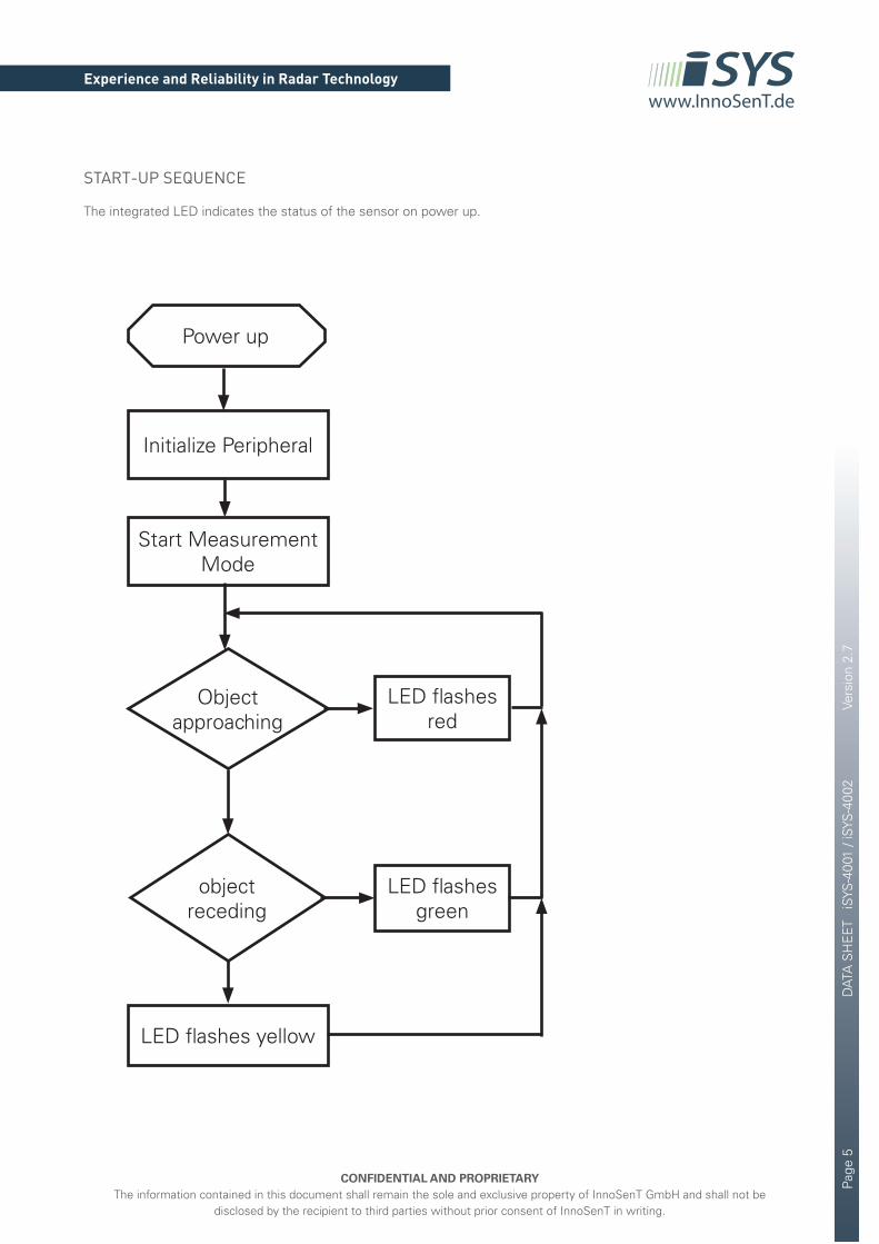
START-UP SEQUENCE
The integrated LED indicates the status of the sensor on power up.
Power up
Initialize Peripheral
LED flashes red
LED flashes yellow
LED flashes green
Start Measurement Mode
Object approaching
object receding

Page
6
DAT
A S
HE
ET
iSYS
-400
1 / i
SYS
-400
2
Vers
ion
2.7
CONFIDENTIAL AND PROPRIETARYThe information contained in this document shall remain the sole and exclusive property of InnoSenT GmbH and shall not be
disclosed by the recipient to third parties without prior consent of InnoSenT in writing.
Experience and Reliability in Radar Technologywww.InnoSenT.de
APPROVAL
This Data Sheet contains the technical specifications of the described product. Changes of the specification must be in written form. All previous versions of this Data Sheet are no longer valid.
VERSION DATE COMMENT
1.0 08.11.2013 initial release
1.1 22.03.2013 changes in mechanical outlines
2.0 04.06.2013 changes in frequency channels and maximum detection distance
2.1 21.08.2013 minor changes
2.2 19.11.2013 iSYS-4002 specification included
2.3 14.07.2014 changes in RoHS-Info
2.4 06.10.2014 changes in supply current
2.5 12.03.2015 changes in digital current
2.6 29.06.2016 outputs changed to open drain
2.7 19.07.2016 adding new transmit frequencies channels
InnoSenT GmbHAm Rödertor 3097499 DonnersdorfGERMANY
Tel.:E-Mail:URL:
+49 (0)9528 - 9518 - [email protected]
QUICK-START-GUIDE
For an easy start with the iSYS-4001 a quick-start-guide is available at www.InnoSenT.de
GUI - Graphical User Interface
The iSYS-4001 can be configured by using the corresponding GUI. The actual Software can be downloaded under www.InnoSenT.de.
www.InnoSenT.de
iSYS-4001iSYS-4002iSYS-4003iSYS-4010iSYS-4013
GUI interface - V2.3
Power up
Initialize Peripheral
LED flashes red
LED flashes yellow
LED flashes green
Start Measurement Mode
Object approaching
object receding
iSYS-4001iSYS-4002iSYS-4003
quick-start guide V2.2
www.InnoSenT.de
30°45°
60°
2.2m
iSYS-4010iSYS-4013