data sheet aat2605 - skyworks solutions · aat2605 data sheet five-channel 300ma ... 30 55 µa i...
TRANSCRIPT

1
AAT2605DATA SHEET
Five-Channel 300mA LDO Regulator
Skyworks Solutions, Inc. • Phone [781] 376-3000 • Fax [781] 376-3100 • [email protected] • www.skyworksinc.com 202183A • Skyworks Proprietary Information • Products and Product Information are Subject to Change Without Notice. • July 24, 2012
General DescriptionThe AAT2605 is a member of Skyworks' Total Power Management IC (TPMIC™) product family. It contains five fully integrated 300mA low dropout (LDO) regulators in a small Pb-free 14-pin 3mm x 3mm TDFN package, making it ideal for space-constrained systems.
The AAT2605 features low power consumption, low drop-out, and high noise immunity from the input power sup-ply. Each channel consumes a mere 30µA of current when enabled, features 250mV of dropout at 250mA and 68dB of power supply rejection at 10kHz. Each channel has its own enable pin and uses a small 1µF output capacitor. Output voltages are factory One Time Programmable (OTP) between 0.6V and 3.7V with 100mV increment and typical regulation accuracy is ±1%. LDO1 and LDO2 share the same input voltage, as do LDO3 and LDO4 while LDO5 has its own independent input.
The AAT2605 is a safe solution that integrates an over-current limit for each channel and an over-thermal pro-tection. The device is rated over a temperature range of -40°C to 85°C.
Features• 2.7V to 5.5V Operating Input Voltage Range• 5 Outputs with Factory Programmable Voltages from
0.6V to 3.7V • 300mA Output Current Per Channel• 3mmx3mm, 14-Pin TDFN Package• ±1% Typical Accuracy• Low 30µA Quiescent Current• High PSRR (68dB @10KHZ)• 250mV Dropout Voltage at 250mA• Independent Enable• Over-Current Protection• Over-Thermal Protection
Applications• Cellular Applications• Handheld Products• Media Players (MP4 Players)• Portable Navigation Devices (PND)
Typical Application
1µFC8
1µFC7
1µFC6
1µFC5
1µFC4
TP2
VIN34TP3
VIN5
TP4
VO5
TP5
VO4
TP6
VO3
TP7
VO2
TP8
VO1
VIN34
VIN5
VIN346
EN33
EN11
5
7
VIN5 GND
VCC
8
EN22
VO1 13
VO3 11
VO5 9
VO4 10
VO2 12
EN514
EN44
U1AAT2605_TDFN33-14
C12.2µF
TP1
VCC
VCC
C22.2µF
C32.2µF
Power Supply Rejection Ratio, PSRR (VIN(DC) = 5V; VOUT = 1.9V; IOUT = 100mA)
Frequency (Hz)
PSR
R (d
B)
100 100010 10000 100000 10000000
10
20
30
40
50
60
70
80

2
AAT2605DATA SHEET
Five-Channel 300mA LDO Regulator
Skyworks Solutions, Inc. • Phone [781] 376-3000 • Fax [781] 376-3100 • [email protected] • www.skyworksinc.com 202183A • Skyworks Proprietary Information • Products and Product Information are Subject to Change Without Notice. • July 24, 2012
Pin Descriptions
Pin # Symbol Function1 EN1 LDO1 enable; active high.2 EN2 LDO2 enable; active high.3 EN3 LDO3 enable; active high.4 EN4 LDO4 enable; active high.5 VCC Input to power control circuit, LDO1, and LDO2. 6 VIN3/4 Input to LDO3 and LDO4.7 GND Analog ground.8 VIN5 Input to LDO5.9 VO5 LDO5 output voltage. 10 VO4 LDO4 output voltage. 11 VO3 LDO3 output voltage. 12 VO2 LDO2 output voltage.13 VO1 LDO1 output voltage. 14 EN5 LDO5 enable; active high.
Pin Configuration
TDFN33-14 (Top View)
EN1EN2EN3
1
EN4VCC
VIN3/4
EN5VO1VO2VO3VO4VO5
2
3
4
5
6
GND 7
12
11
14
13
10
9
VIN58

3
AAT2605DATA SHEET
Five-Channel 300mA LDO Regulator
Skyworks Solutions, Inc. • Phone [781] 376-3000 • Fax [781] 376-3100 • [email protected] • www.skyworksinc.com 202183A • Skyworks Proprietary Information • Products and Product Information are Subject to Change Without Notice. • July 24, 2012
1. Stresses above those listed in Absolute Maximum Ratings may cause permanent damage to the device. Functional operation at conditions other than the operating conditions specified is not implied. Only one Absolute Maximum Rating should be applied at any one time.
2. Mounted on an FR4 board.
Absolute Maximum Ratings1
Symbol Description Value UnitsVIN VCC, VIN3/4, VIN5, EN1, EN2, EN3, EN4, EN5 to GND -0.3 to 6.5 V
Thermal Information2
Symbol Description Value UnitsθJA Thermal Resistance 50 °C/WPD Maximum Power Dissipation 2 WTJ Operating Temperature Range -40 to 150
°CTS Storage Temperature Range -65 to 150TLEAD Maximum Soldering Temperature (at leads, 10 sec.) 300

4
AAT2605DATA SHEET
Five-Channel 300mA LDO Regulator
Skyworks Solutions, Inc. • Phone [781] 376-3000 • Fax [781] 376-3100 • [email protected] • www.skyworksinc.com 202183A • Skyworks Proprietary Information • Products and Product Information are Subject to Change Without Notice. • July 24, 2012
1. Specification over the -40°C to +85°C operating temperature range is assured by design, characterization and correlation with statistical process controls.
Electrical Characteristics1
VCC = VIN3/4 = VIN5 = 5.0V, -40°C ≤ TA ≤ +85°C, unless noted otherwise. Typical values are TA = 25°C.
Symbol Description Conditions Min Typ Max UnitsLogic Control / Protection
VENxInput High Threshold 1.4 VInput Low Threshold 0.3 V
Input SupplyVCC, VIN3/4,
VIN5Input Voltage Range 2.7 5.5 V
UVLO Under-Voltage Lockout ThresholdVCC Falling 2
VVCC Rising 2.2
Low-Dropout Regulator (LDO1:LDO5)
VLDO LDO Output Voltage ILDO = 1mA to 250mA, OTP per requirement 0.6V VINLDO -
VDOV
LDO Accuracy ILDO = 10mA -3 +3 %
IQ LDO Quiescent Current VINx = 5.0V, added quiescent current when LDO is enabled 30 55 µA
ISHDN Shutdown Current VINx = 5.0V, EN = GND 1 µALine Regulation ILDO = 10mA 0.1 %/V
VDO Dropout Voltage ILDO = 250mA 250 500 mV
PSRR Power Supply Rejection Ratio VINx = 5.0V, EN = High, ILDO = 100mA, f = 10KHz, VOx = 1.8V 68 dB
ILDO(LIM) LDO Current Limit 300 mAThermal
TSD Over-Temperature Shutdown Threshold Rising 145 °CTHYS Over-Temperature Shutdown Hysteresis 25 °C

5
AAT2605DATA SHEET
Five-Channel 300mA LDO Regulator
Skyworks Solutions, Inc. • Phone [781] 376-3000 • Fax [781] 376-3100 • [email protected] • www.skyworksinc.com 202183A • Skyworks Proprietary Information • Products and Product Information are Subject to Change Without Notice. • July 24, 2012
Programming Output Voltages via OTP
Regulator Output Voltage Range ResolutionLDO1 0.6V 3.7V 100mVLDO2 0.6V 3.7V 100mVLDO3 0.6V 3.7V 100mVLDO4 0.6V 3.7V 100mVLDO5 0.6V 3.7V 100mV
Block Diagram
LDO1
LDO2
LDO3
LDO4
LDO5
VCC Bias, Control,and OTP
AAT2605
VO1
C22.2µF
C12.2µF
C81µF
C71µF
C61µF
C51µF
C41µF
C32.2µF
OutputVoltage Trim
OutputVoltage Trim
OutputVoltage Trim
OutputVoltage Trim
OutputVoltage Trim
EN1
VO2EN2
VO3EN3
VO4EN4
VO5EN5
VIN3/4
VIN5
GND

6
AAT2605DATA SHEET
Five-Channel 300mA LDO Regulator
Skyworks Solutions, Inc. • Phone [781] 376-3000 • Fax [781] 376-3100 • [email protected] • www.skyworksinc.com 202183A • Skyworks Proprietary Information • Products and Product Information are Subject to Change Without Notice. • July 24, 2012
Typical Characteristics
Load Regulation(VOUT = 1V)
Output Current (mA)
Load
Reg
ulat
ion
(%)
0.1 1 10 100 1000-0.5
-0.4
-0.3
-0.2
-0.1
0.0
0.1
0.2
0.3
0.4
0.5VIN = 5.5VVIN = 4.2V VIN = 3.6VVIN = 2.7V
Load Regulation(VOUT = 3V)
Output Current (mA)
Load
Reg
ulat
ion
(%)
0.1 1 10 100 1000-0.5
-0.4
-0.3
-0.2
-0.1
0.0
0.1
0.2
0.3
0.4
0.5VIN = 5.5VVIN = 4.2V VIN = 3.6VVIN = 2.7V
Line Regulation(VOUT = 1V)
Input Voltage (V)
Line
Reg
ulat
ion
(%)
2.7 3.1 3.5 3.9 4.3 4.7 5.1 5.5-0.5
-0.4
-0.3
-0.2
-0.1
0.0
0.1
0.2
0.3
0.4
0.5IOUT = 300mAIOUT = 150mAIOUT = 100mA IOUT = 1mA
Line Regulation(VOUT = 3V)
Input Voltage (V)
Line
Reg
ulat
ion
(%)
2.7 3.1 3.5 3.9 4.3 4.7 5.1 5.5-0.5
-0.4
-0.3
-0.2
-0.1
0.0
0.1
0.2
0.3
0.4
0.5IOUT = 300mAIOUT = 150mAIOUT = 100mA IOUT = 1mA
Output Voltage Error vs. Temperature(LDO VOUT = 1V)
Temperature (°C)
Out
put V
olta
ge E
rror
(%)
7550250-25-50 100-1.0
-0.8
-0.6
-0.4
-0.2
0.0
0.2
0.4
0.6
0.8
1.0
IOUT = 1mAIOUT = 250mA
Output Voltage Error vs. Temperature(LDO VOUT = 3V)
Temperature (°C)
Out
put V
olta
ge E
rror
(%)
7550250-25-50 100-1.0
-0.8
-0.6
-0.4
-0.2
0.0
0.2
0.4
0.6
0.8
1.0
IOUT = 1mAIOUT = 250mA

7
AAT2605DATA SHEET
Five-Channel 300mA LDO Regulator
Skyworks Solutions, Inc. • Phone [781] 376-3000 • Fax [781] 376-3100 • [email protected] • www.skyworksinc.com 202183A • Skyworks Proprietary Information • Products and Product Information are Subject to Change Without Notice. • July 24, 2012
Typical Characteristics
Supply Current vs. Supply Voltage(Contributed By Each LDO)
Supply Voltage (V)
Supp
ly C
urre
nt (μ
A)
2.7 3.1 3.5 3.9 4.3 4.7 5.1 5.525
26
27
28
29
30
31
32
33
34
35
Load Transient(VOUT = 1.85V; VIN = 3.6V; IOUT = 30mA to 300mA)
Time (200µs/div)
Out
put V
olta
ge(5
0mV/
div)
(top
) Output C
urrent(200m
A/div) (bottom
)
1.80
1.85
1.90
1.95
2.00
-0.2
0.0
0.2
0.4
Power Supply Rejection Ratio, PSRR (VIN(DC) = 5V; VOUT = 1.9V; IOUT = 100mA)
Frequency (Hz)
PSR
R (d
B)
100 100010 10000 100000 10000000
10
20
30
40
50
60
70
80
8
AAT2605DATA SHEET
Five-Channel 300mA LDO Regulator
Skyworks Solutions, Inc. • Phone [781] 376-3000 • Fax [781] 376-3100 • [email protected] • www.skyworksinc.com 202183A • Skyworks Proprietary Information • Products and Product Information are Subject to Change Without Notice. • July 24, 2012
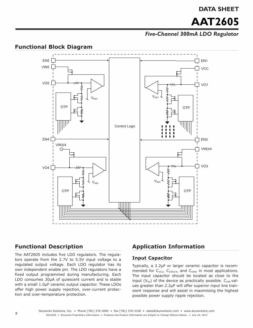
Functional DescriptionThe AAT2605 includes five LDO regulators. The regula-tors operate from the 2.7V to 5.5V input voltage to a regulated output voltage. Each LDO regulator has its own independent enable pin. The LDO regulators have a fixed output programmed during manufacturing. Each LDO consumes 30μA of quiescent current and is stable with a small 1.0μF ceramic output capacitor. These LDOs offer high power supply rejection, over-current protec-tion and over-temperature protection.
Application Information
Input CapacitorTypically, a 2.2μF or larger ceramic capacitor is recom-mended for CVCC, CVIN3/4, and CVIN5 in most applications. The input capacitor should be located as close to the input (VIN) of the device as practically possible. CVIN val-ues greater than 2.2μF will offer superior input line tran-sient response and will assist in maximizing the highest possible power supply ripple rejection.
Functional Block Diagram
Control Logic
OTP
EN3
VIN3/4
VO3
OTP
VCC
VO1
EN1
VIN3/4
OTP
VREF
VREFVREF
VREF
EN4
VO4
OTP
EN5
VIN5
VO5

9
AAT2605DATA SHEET
Five-Channel 300mA LDO Regulator
Skyworks Solutions, Inc. • Phone [781] 376-3000 • Fax [781] 376-3100 • [email protected] • www.skyworksinc.com 202183A • Skyworks Proprietary Information • Products and Product Information are Subject to Change Without Notice. • July 24, 2012
Output CapacitorFor proper load voltage regulation and operational sta-bility, a capacitor is required between pins VOUT and GND. The COUT capacitor connection to the LDO regulator ground pin should be made as direct as practically pos-sible for maximum device performance.
The AAT2605's LDO regulators have been specifically designed to function with very low ESR ceramic capaci-tors. Although the device is intended to operate with these low ESR capacitors, it is stable over a very wide range of capacitor ESR, thus it will also work with higher ESR tantalum or aluminum electrolytic capacitors. However, for best performance, ceramic capacitors are recommended.
Typical output capacitor values for maximum output cur-rent conditions range from 1μF to 10μF.
Thermal CalculationsThere are two types of losses associated with the AAT2605 total power management solution (five LDO regulators): conduction losses and quiescent current losses. Conduction losses are associated with the power loss of the voltage difference across the pass switch/FET of the five LDO regulators. At full load, a simplified form of the losses is given by the following (quiescent losses are ignored, since conduction losses are so dominant):
PLDO1 = ILDO1 · (VCC - VO1)
PLDO2 = ILDO2 · (VCC - VO2)
PLDO3 = ILDO3 · (VIN3/4 - VO3)
PLDO4 = ILDO4 · (VIN3/4 - VO4)
PLDO5 = ILDO5 · (VIN5 - VO5)
PTOTAL = PLDO1 + PLDO2 + PLDO3 + PLDO4 + PLDO5
LayoutThe suggested PCB layout for the AAT2605 is shown in Figures 2 and 3. The following guidelines should be used to help ensure a proper layout.
1. The input capacitors (C1, C2 and C3 should connect as closely as possible to VCC, VIN3/4 and VIN5 (Pins 5, 6 and 8) and GND (Pin 7).
2. The resistance of the trace from the load return to GND (Pin 7) should be kept to a minimum. This will help to minimize any error in DC regulation due to differences in the potential of the internal signal ground and the power ground.
3. For good thermal coupling, PCB vias are required from the pad for the TDFN33-14's exposed paddle to the ground plane.

10
AAT2605DATA SHEET
Five-Channel 300mA LDO Regulator
Skyworks Solutions, Inc. • Phone [781] 376-3000 • Fax [781] 376-3100 • [email protected] • www.skyworksinc.com 202183A • Skyworks Proprietary Information • Products and Product Information are Subject to Change Without Notice. • July 24, 2012
1µFC8
1µFC7
2.2µFC2
1µFC6
1µFC5
2.2µFC3
1µFC4
TP2
VIN34
TP3
VIN5
TP4
VO5
TP5
VO4
TP6
VO3
TP7
VO2
TP8
VO1
R51M
R41M
R31M
R21M
R11M
1 10
SW1
VIN34
VIN34
VIN5
VIN5
VIN346
EN33
EN11
VCC
5G
ND
7
VIN58
EN22
VO1 13
VO3 11
VO5 9
VO4 10
VO2 12
EN514
EN44
U1AAT2605_TDFN33-14
2.2µFC1
TP1
VCC
VCC
VCC
Figure 1: AAT2605 Evaluation Board Schematic.
Figure 2: AAT2605 Evaluation Board Figure 3: AAT2605 Evaluation Board Top Side Layout. Bottom Side Layout.

11
AAT2605DATA SHEET
Five-Channel 300mA LDO Regulator
Skyworks Solutions, Inc. • Phone [781] 376-3000 • Fax [781] 376-3100 • [email protected] • www.skyworksinc.com 202183A • Skyworks Proprietary Information • Products and Product Information are Subject to Change Without Notice. • July 24, 2012
1. XYY = assembly and date code.2. Sample stock is generally held on part numbers listed in BOLD.3. The leadless package family, which includes QFN, TQFN, DFN, TDFN and STDFN, has exposed copper (unplated) at the end of the lead terminals due to the manufacturing
process. A solder fillet at the exposed copper edge cannot be guaranteed and is not required to ensure a proper bottom solder connection.
Ordering Information
Package Marking1 Part Number (Tape and Reel)2
TDFN33-14 9VXYY AAT2605IWO-1-T1
Skyworks Green™ products are compliant with all applicable legislation and are halogen-free.For additional information, refer to Skyworks Definition of Green™, document number SQ04-0074.
Package Information
TDFN33-143
Top View Bottom View
3.000 ± 0.050
Index Area
3.00
0 ±
0.05
0
Detail "A"
1.650 ± 0.0502.
500 ±
0.05
0
0.20
3 R
EF
0.75
0 ±
0.05
0
0.000 + 0.100- 0.000
Detail "A"
Side View
0.425 ± 0.050
0.40
0 B
SC
0.18
0 ±
0.05
0
Pin 1 Indicator(Optional)
All dimensions in millimeters.

12
AAT2605DATA SHEET
Five-Channel 300mA LDO Regulator
Skyworks Solutions, Inc. • Phone [781] 376-3000 • Fax [781] 376-3100 • [email protected] • www.skyworksinc.com 202183A • Skyworks Proprietary Information • Products and Product Information are Subject to Change Without Notice. • July 24, 2012
Copyright © 2012 Skyworks Solutions, Inc. All Rights Reserved.
Information in this document is provided in connection with Skyworks Solutions, Inc. (“Skyworks”) products or services. These materials, including the information contained herein, are provided by Skyworks as a service to its customers and may be used for informational purposes only by the customer. Skyworks assumes no responsibility for errors or omissions in these materials or the information contained herein. Sky-works may change its documentation, products, services, specifications or product descriptions at any time, without notice. Skyworks makes no commitment to update the materials or information and shall have no responsibility whatsoever for conflicts, incompatibilities, or other difficulties arising from any future changes.
No license, whether express, implied, by estoppel or otherwise, is granted to any intellectual property rights by this document. Skyworks assumes no liability for any materials, products or information provided here-under, including the sale, distribution, reproduction or use of Skyworks products, information or materials, except as may be provided in Skyworks Terms and Conditions of Sale.
THE MATERIALS, PRODUCTS AND INFORMATION ARE PROVIDED “AS IS” WITHOUT WARRANTY OF ANY KIND, WHETHER EXPRESS, IMPLIED, STATUTORY, OR OTHERWISE, INCLUDING FITNESS FOR A PARTICULAR PURPOSE OR USE, MERCHANTABILITY, PERFORMANCE, QUALITY OR NON-INFRINGEMENT OF ANY INTELLECTUAL PROPERTY RIGHT; ALL SUCH WARRANTIES ARE HEREBY EXPRESSLY DISCLAIMED. SKYWORKS DOES NOT WARRANT THE ACCURACY OR COMPLETENESS OF THE INFORMATION, TEXT, GRAPHICS OR OTHER ITEMS CONTAINED WITHIN THESE MATERIALS. SKYWORKS SHALL NOT BE LIABLE FOR ANY DAMAGES, IN-CLUDING BUT NOT LIMITED TO ANY SPECIAL, INDIRECT, INCIDENTAL, STATUTORY, OR CONSEQUENTIAL DAMAGES, INCLUDING WITHOUT LIMITATION, LOST REVENUES OR LOST PROFITS THAT MAY RESULT FROM THE USE OF THE MATERIALS OR INFORMATION, WHETHER OR NOT THE RECIPIENT OF MATERIALS HAS BEEN ADVISED OF THE POSSIBILITY OF SUCH DAMAGE.
Skyworks products are not intended for use in medical, lifesaving or life-sustaining applications, or other equipment in which the failure of the Skyworks products could lead to personal injury, death, physical or en-vironmental damage. Skyworks customers using or selling Skyworks products for use in such applications do so at their own risk and agree to fully indemnify Skyworks for any damages resulting from such improper use or sale.
Customers are responsible for their products and applications using Skyworks products, which may deviate from published specifications as a result of design defects, errors, or operation of products outside of pub-lished parameters or design specifications. Customers should include design and operating safeguards to minimize these and other risks. Skyworks assumes no liability for applications assistance, customer product design, or damage to any equipment resulting from the use of Skyworks products outside of stated published specifications or parameters.
Skyworks, the Skyworks symbol, and “Breakthrough Simplicity” are trademarks or registered trademarks of Skyworks Solutions, Inc., in the United States and other countries. Third-party brands and names are for identification purposes only, and are the property of their respective owners. Additional information, including relevant terms and conditions, posted at www.skyworksinc.com, are incorporated by reference.