data link layer - my.fit.edumy.fit.edu/~gmarin/cse5231/olddatalinklayersect3.pdf•the 4 codes might...
TRANSCRIPT

Data Link Layer 3-1
Data Link Layer
This information is provided only for use by students in CSE5231. No
further distribution is authorized. Such distribution may violate existing copyright protection.

Data Link Layer 3-2
Direct Link Network Requirements:
Nodes must be connected with suitable mediaBits must be encoded onto media (physical layer)Bits must be organized into protocol data units (PDUs) usually called frames at this layer (link layer)Any errors must be detected and handled (link layer)If multiple hosts attached, then access to the media must be controlled (mac layer)Sender and Receiver must coordinate their exchanges of data (link layer).

Data Link Layer 3-3
Layers and PDUs – using TCP/IP over LAN
Application Layer: Message dataTransport Layer: Segment[Message data]Network Layer:
Datagram[Segment[Message data]]Data Link Layer:
Frame[Datagram[Segment[Message data]]]Physical Layer:
110001110101… bitssignaling

Data Link Layer 3-4
Adaptors Communicating
link layer implemented in “adaptor” (aka NIC)
Ethernet card, PCMCIA card, 802.11 card
sending side:encapsulates datagram in a frameadds error checking bits, rdt, flow control, etc.
receiving sidelooks for errors, flow control, etcextracts datagram, passes to rcving node
link & physical layers
sendingnode
frame
rcvingnode
datagram
frame
adapter adapter
link layer protocol

Data Link Layer 3-5

Data Link Layer 3-6
Common Types of Local Links
Cable Typical Bandwidth
Distances
Category 5 Twisted Pair
10-100 Mbps 100 m
Thin-net Coax 10-100 Mbps 200 m
Thick-net Coax 10-100 Mbps 500 m
Multimode Fiber 100 Mbps 2 km
Single-mode Fiber
100-2400 Mbps 40 km

Data Link Layer 3-7
Common Types of Carrier Links
Service Bandwidth
DS1 or T1 1.544 Mbps (24x64kbps)
DS3 or T3 44.736 Mbps (28 DS1s)
STS-1 51.840 Mbps
STS-3 or OC-3 155.250 Mbps
STS-12 622.080 Mbps
STS-48 2.48832 Gbps
STS-192 9.95328 Gbps

Data Link Layer 3-8
Common Home Services
Service Bandwidth
POTS 28.8 – 56 kbps
ISDN 64 – 128 kbps
DSL 16 – 55.2 kbps
CATV 20 – 40 Mbps

Data Link Layer 3-9
Services Usually Provided to the Network Layer by the Link Layer
• Framing• Error control• In-order delivery• Flow control

Data Link Layer 3-10
Services Provided to Network Layer (2)
Placement of the data link protocol.

Data Link Layer 3-11
Data Link Layer Major Functions
Create outbound frames and detect inbound framesInsure frames are error free unless no error control is requiredCooperate with peer in running an agreed upon link protocol

Data Link Layer 3-12
Creating/Detecting FramesPhysical layer delivers raw bits
Received bits may be fewer or greater than the number transmittedReceived bits may contain errors
Data Link Layer must determine when frame begins and ends.
Generally cannot rely on gaps between frames.Header and trailer include start and end “flags.”Example DLE STX to start and DLE ETX to end...or use a specific bit pattern 01111110

Data Link Layer 3-13
Bit Stuffing
(a) The original data (flag is 01111110).(b) The data as they appear on the line.(c) The data as they are stored in receiver’s
memory after destuffing.

Data Link Layer 3-14
Frame Header & Trailer
Relationship between packets and frames.

Data Link Layer 3-15
Framing
A character stream. (a) Without errors. (b) With one error.

Data Link Layer 3-16
Example Data Link Protocols Example Data Link Protocols (Business) (Business)
HDLC(ISO) (similar to SDLC(IBM), ADCCP(ANSI), LAPB(CCITT))Bit orientedBit stuffing for "data transparency"Checksum uses CCITT generator polynomial.Format below for point-to-point or polling.
control field used for seq no, acks, etc.

Data Link Layer 3-17
Control Fields: (a) Info Frame, (b) Control Fields: (a) Info Frame, (b) Supervisory Frame, Supervisory Frame, (c) Unnumbered Frame(c) Unnumbered FrameSliding window, 3-bit seq no, 7 acks max outstanding (window size)Seq in (a) is frame seq numberNext is for piggybacked ackP/F used in polling
P invites terminal to send dataTerminal responds with all P's except Final
P may be used to force supervisory frame containing ack.Type indicates kinds of supervisory frames (0-ack,1-nak,2-ack but NR, 3-selective reject)

Data Link Layer 3-18
Point-to-Point Protocol: PPP Point-to-Point Protocol: PPP (RFC 1661,1662,1663)(RFC 1661,1662,1663)
Supports error detection, multiple protocols, and authenticationIncludes flags to start and end framesIncludes link control protocol (LCP)
negotiate: max payload size, authentication use, protocol used, header compression options, line quality testing, CRC length...
Includes network control protocol (NCP) appropriate to supported network layers

Data Link Layer 3-19
Example: PPP Setup and Example: PPP Setup and Takedown (with modems)Takedown (with modems)
Modems establish physical connectionPC (host) sends PPP frames to internet routerLCP used to establish initial link parameters and authenticate if desired.NCP (appropriate to network Layer protocol) configures network layer
PC gets IP host address from routerData transmission phaseNCP releases network layer connection
Frees buffersFrees IP address for use elsewhere
LCP shuts down DLC

Data Link Layer 3-20
PPP Frame StructurePPP Frame Structure
Start/End of Frame Flag: 01111110Address: 11111111 "all stations"Control Field: Unnumbered Frame
note no seq numbers and no acksLCP can negotiate to omit Address & Control
Protocol ID: LCP,NCP,IP,IPX,Appletalk,APPN,...Payload field defaults to 1500 bytes
Can be negotiated using LCPChecksum (for CRC) is usually 16 bits (32 option)

Data Link Layer 3-21
LCP Frame TypesLCP Frame Types

Data Link Layer 3-22
Data Link Layer Major Functions
Create outbound frames and detect inbound framesInsure frames are error free unless no error control is requiredCooperate with peer in running an agreed upon link protocol

Data Link Layer 3-23
Error Detection (and Correction)Error Detection (and Correction)
Two basic philosophiesError correction: Include enough redundant bits to enable error correctionError detection: Include enough redundant bits to enable error detection only then request retransmission of frame

Error Illustration
Direct Link Networks 2-24
Code Codeword00 00001 10110 01111 110
•The 4 codes might represent messages to be sent such as “buy,” “sell,” “hold,” and “avoid.”•Each code is represented by a larger codeword that (in this case) contains 1 “redundant” bit.•The codewords are chosen to maximize the distance between each pair of codewords. Here each pair is a distance of 2 (bits) apart. •2 (in this case) is the “hamming distance” between each pair.•The minimum pair distance is the hamming distance of the code.

Error Illustration (continued)
Direct Link Networks 2-25
Code Codeword00 00001 10110 01111 110
•If one bit is flipped, the error does not produce a valid codeword and receiver can detect an error (error detection). •Flipping one bit in 101 can produce 111. Notice that 111 is one bit away from both 101 and 110. Therefore no error correction is possible in this example.•Flipping 2 bits might produce another valid codeword, and no error would be detected (000 -> 101).•Notice that flipping 3 bits would be detected in each case.

Error Illustration (continued)
Data Link Layer 3-26
Code Codeword00 0000001 1010110 0111111 11010
•d[00000,10101]=3; d[00000,01111]=4; d[00000,11010]=3•d[10101,01111]=3; d[10101,11010]=3•d[01111,11010]=3•Hamming distance of code = 3•Flipping 1 bit cannot produce a valid codeword•Any 1-bit error can be corrected
•Example 10101->10111 •1 bit from 10101•4 bits from 00000•2 bits from 01111•3 bits from 11010

Data Link Layer 3-27
Hamming DistanceThe Hamming Distance between two codewords is the number of bits in which they differ
10001001 and 10110001 have a Hamming distance of 3 because they differ in bits 3,4,5A “codeword” is composed of m message bits within a total of n bits.Thus, messages are possible within a set of codewords.It follows that r=n-m bits are available to help separate the messages in the code space.
2m 2n

Data Link Layer 3-28
Hamming Distance of Code
The hamming distance of a code is the distance between its two closest codewords.
To detect errors requires a code.To correct errors requires a code.
Example codewords 011 101Hamming Distance = 2 110 000
The dominant approach is error detection plus retransmission.
d 1d +d 2 1d +

Data Link Layer 3-29
Hamming Example
00000 00111 11010 1110100000 0 3 3 400111 0 4 311010 0 311101 0
Symbols Codewords00 0000001 0011110 1101011 11101
Hamming Distances
Hamming distance of the code is 3.
•Change any one bit of the transmitted codeword and the received codeword can be CORRECTED.
•Change two bits and the received codeword can be DETECTED perhaps not corrected.
00000
1110111000 What was sent?

Data Link Layer 3-30
Common Error Detection MechanismsCommon Error Detection Mechanisms
Parity BitAdd 1 bit per frame so that frame is always even or always oddWill catch all single-bit errorsProbability of catching a burst error is 0.5
Matrixed Parity BitsSend blocks of frames as matrix n bits wide and k bits high.Compute separate parity bit for each column and add as k+1st row. Transmit row 1, row 2, ... row k+1 and accept only if all parity bits are correct.
Cyclic Redundancy Code

Data Link Layer 3-31
1 0 0 11 1 1 00 0 1 01 0 1 0
Example: Matrixed Parity BitsExample: Matrixed Parity Bits4 bits wide 3 bits deep (odd parity)4 bits wide 3 bits deep (odd parity)First 3 rows for data. Last row for parity bits.
Will catch an error burst of length 7 or less.Will miss a burst of length 8.Will catch an error burst of length 9 - 15.Will miss an error burst of length 16.

Data Link Layer 3-32
Cyclic Redundancy Check-1, 2 0
1 21 2 0
5 2
Think of representing an bit message frame, ,...,
as ... , an 1 degree polynomialwith binary coefficients. Example: 100101 is represented as 1.Polynomial a
m m
m mm m
m i i i
i x i x i m
x x
−
− −− −
−
+ + + −
+ +rithmetric is done "mod 2" so that addition and
subtraction are equivalent to "exclusive or."0 0 00 1 11 0 11 1 0 with no carries for addition or borrows for subtraction.
+ =+ =+ =+ =

Data Link Layer 3-33
CRC FundamentalsCRC FundamentalsTransmit codewords of length m+r at the DLC layer with m message bits and r checksum bits.Message bits map to polynomial M(x) of order m-1.Checksum bits map to polynomial C(x) of order r-1.T(x) is polynomial that corresponds to the entire transmitted codeword of length m+r (degree m+r-1)Checksum is computed before transmission such that the polynomial T(x) is divisible by a generator polynomial, G.
The receiver also knows G and determines that an error has occurred if T(x)/G(x) is anything other than zero.
1 21 2 1( ) ... 1r r r
r rG x x g x g x g x− −− −= + + + + +

Data Link Layer 3-34
CRC ExampleTransmit Function

Data Link Layer 3-35
Error Detecting Power of CRCError Detecting Power of CRCAssume received polynomial is T(x)+E(x)
Each 1-bit coefficient in E(x) corresponds to errored bit of T.Receiver thus divides (T(x)+E(x))/G(x)=E(x)/G(x) by design.
If G(x) is a factor of the error polynomial, the error will not be detected.Single bit error implies for some bit position i=1,2,...,n
As long as G(x) contains two or more terms, it cannot divide so all single bit errors are detected.
Two single-bit errors (double bit error) imply (say)Write . If we make sure G cannot divide for all k=1,2,...,n then G will catch all double bit errors. Example, for k<32,768
Odd number of erors means E(x) has odd number of terms.It is known that no polynomial with oddd number of terms is divisible by x+1 (mod 2).Thus, make sure G(x) has x+1 as factor and catch all errors involving odd number of bits.
Most important: CRC with r check bits will detect all burst errors of length less than or equal to r (read discussion in text).
( ) iE x x=ix
( ) ,i jE x x x i j= + >( ) (1 )i i jE x x x −= + or 1k kx x +
15 14 1 will not divide 1kx x x+ + +

Data Link Layer 3-36
Common CRC PolynomialsCRC Polynomial
CRC-8 (ATM)
CRC-10 (ATM)
CRC-12CRC-16CRC-CITT (HDLC)
CRC-32 (Ethernet)
8 2 1x x x+ + +10 9 5 4 1x x x x x+ + + + +
12 11 3 2 1x x x x+ + + +16 15 2 1x x x+ + +15 12 5 1x x x+ + +
32 26 23 22 16 12 11 10
8 7 5 4 2 1x x x x x x x xx x x x x x+ + + + + + +
+ + + + + + +

Probabilities of Errors
Data Link Layer 3-37
If we assume that the probability that bit is errored is independent of the probabilitythat bit is errored for (not really true), then the probability of exactly errorsin a codeword of lengt
ij i j k=
( ) ( )
h has a binomial distribution. If the random variable
indicates the number of bit errors, then its pmf is 1
for 1, 2,..., .
n kkX
n Xn
p k p pk
k n
−⎛ ⎞= −⎜ ⎟⎝ ⎠
=
( ) ( )32
32
3
Example: Suppose that a codeword has length 32 bits and the probability of a bit error is 0.01. (a) What is the probability that 3 or more bits will be errors?
32 3 0.01 0.99i
i
P Xi=
⎛ ⎞≥ = ⎜ ⎟
⎝ ⎠∑
( ) ( )
3
832 22
1
3.993 10 .
(b) What is the probability that all the even bits will be errors?32
even 0.01 0.99 0.037.2
i
ii
i
P Xi
− −
−
=
= ×
⎛ ⎞= =⎜ ⎟
⎝ ⎠∑

Direct Link Networks 2-38
Checksum in IP Datagram
ver length
32 bits
data (variable length,typically a TCP
or UDP segment)
16-bit identifierInternetchecksum
time tolive
32 bit source IP address
IP protocol versionnumber
header length(bytes)
max numberremaining hops
(decremented at each router)
forfragmentation/reassembly
total datagramlength (bytes)
upper layer protocolto deliver payload to
head.len
type ofservice
“type” of data flgs fragmentoffset
upperlayer
32 bit destination IP address
Options (if any) E.g. timestamp,record routetaken, specifylist of routers to visit.
how much overhead with TCP?20 bytes of TCP20 bytes of IP= 40 bytes + app layer overhead

Direct Link Networks 2-39
IP Header Checksum
Used to determine whether bits in IP header have been altered.Sender adds all 16-bit fields in the IP header ignoring any high-order carry bits.
Put 1’s complement of result in checksum field.Receiver adds all 16-bit fields of header including checksum.
Result of all 1’s means no error. Details in RFC 1071. Similar checksums available in TCP header and UDP header.

Data Link Layer 3-40
Data Link Layer Major Functions
Create outbound frames and detect inbound framesInsure frames are error free unless no error control is requiredCooperate with peer in running an agreed upon link protocol

Data Link Layer 3-41
Retransmission StrategiesRetransmission StrategiesGeneral concept of Automatic Repeat Request (ARQ): detect frames with errors at receiving DLC and request transmitting DLC to repeat erroneous frames.Error detection usually done via CRC. Retransmissions handled via retransmission protocol.Correctness Issue: Does the protocol succeed in releasing each packet once (and only once), without errors, from the receiving DLC?Efficiency Issue: How much of the capacity of the channel is wasted by unnecessary waiting or by sending unnecessary transmissions?

Data Link Layer 3-42
Example: Stop-and-W ait with ACK/NAK Example: Stop-and-W ait with ACK/NAK
A transmits a frame to B and waits.If frame ok at B, B sends ACK.If frame in error at B, B sends NAK.ACK and/or NAK also protected with CRC.If A receives ACK, sends next frame.If A receives NAK, sends last frame again.Because the frame or the ACK/NAK can be lost, A maintains a timer and retransmits if "pops."

Data Link Layer 3-43
Potential ProblemsPotential ProblemsThe delay in the channel is arbitrary so A may time out and retransmit the old data in a second frame. (B will not know and will pass duplicate data to NL.)Potential solution: put a sequence number on the frames.Remaining problem: A sends frame k, B receives and sends ack. Ack is delayed. A sends frame k again. B receives (tosses) and sends ack. A receives first ack and sends k+1. A receives second ack and sends k+2 although k+1 has not really been acked by B.Solution: Instead of sending ACK/NAK, B sends a frame (still called ACK) that contains the number of the next frame awaited.

Data Link Layer 3-44
Use of Sliding Window Protocol
May be used to deliver frames reliably across an unreliable link.
May also be associated with other PDUs and operate end-to-end across a network.
May be used to preserve the order in which frames are transmitted.May be used to keep the sender from overwhelming the receiver with traffic (This is called “flow control.”)May be used to keep channel filled for efficient use.

Data Link Layer 3-45
Sliding Window Protocols - Sender
Sender maintains (in a sending “window”) a set of sequence numbers it is permitted to send.
Number of frames outstanding should be large enough to enable efficient use of the channel.Each outbound frame contains a sequence number between Numbers in window represent frames sent and not yet acked.Advance top of window for new frame sent.Advance bottom of window for received ack.
0 and 2 1.n −

Data Link Layer 3-46
Sliding Window Protocols - Receiver
Receiver maintains a “receiving” window.Sequence numbers in the window represent frames that the receiver is allowed to accept. If an arriving frame has a number outside this range, it is discarded. If arriving frame matches number at the “bottom” of the window and is error-free, it is passed to the layer above and top and bottom of receiving window advance by one. If arriving frame is in receiving window but greater than bottom number, it is buffered for later delivery to layer above.
Data Link Layer 3-47
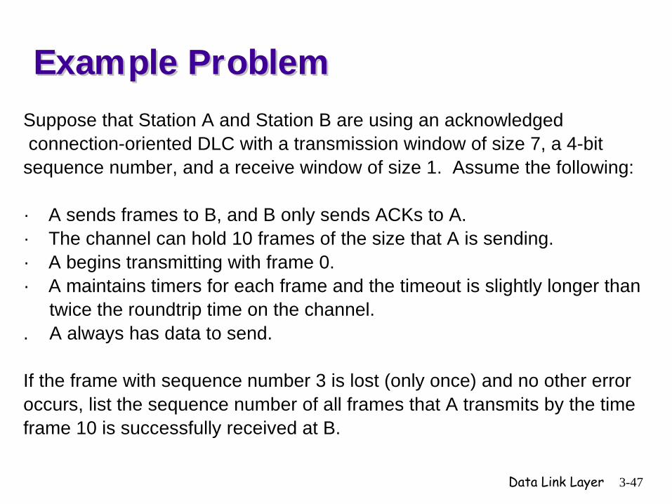
Suppose that Station A and Station B are using an acknowledged connection-oriented DLC with a transmission window of size 7, a 4-bit sequence number, and a receive window of size 1. Assume the following: · A sends frames to B, and B only sends ACKs to A.· The channel can hold 10 frames of the size that A is sending.· A begins transmitting with frame 0.· A maintains timers for each frame and the timeout is slightly longer than twice the roundtrip time on the channel.. A always has data to send.
If the frame with sequence number 3 is lost (only once) and no other erroroccurs, list the sequence number of all frames that A transmits by the timeframe 10 is successfully received at B.
Example ProblemExample Problem

Data Link Layer 3-48
Answer to Example ProblemAnswer to Example ProblemAnswer: A transmits frames: 0,1,2,3,4,5,6
Frame 3 is lost.B Acks 0,1,2 and passes these to NL.
B discards 4,5,6.A moves window to 3 through 9 and transmits 7,8,9.
B discards 7,8,9.Packet 3 times out.A sends 3,4,5,6,7,8,9 (retransmits current window).B acks 3,4,5,6,7,8,9 and passes these to NL.A sends 10,11,12,13,14,15,0 (4-bit seqno)10 received at B.
Final sequence from A: 0,1,2,3,4,5,6,7,8,9,3,4,5,6,7,8,9,10,11,12,13,14,15,0.

Data Link Layer 3-49
Sliding Window Protocols
• A One-Bit Sliding Window Protocol
• A Protocol Using Go Back N• A Protocol Using Selective
Repeat

Data Link Layer 3-50
Selective Repeat
Start Tx b b b Rx b b b
T=0 Tx 0 b b Rx 0 b b
T=1 Tx 0 1 b Rx 0 1 b
T=2 Tx 0 1 2 Rx 0 1 b
R=0 Tx 1 2 b Rx 1 b b
R=1 Tx 2 b b Rx b b b
T=3 Tx 2 3 b Rx b 3 b
T=4 Tx 2 3 4 Rx b 3 4
2 time-out Tx 2 3 4 Rx 2 3 4
T=2
R=4 Tx b b b Rx b b b

Data Link Layer 3-51
Protocol Verification
• Finite State Machine Models• Petri Net Models

Data Link Layer 3-52
The Medium Access Control Sublayer
Data Link Layer 3-53
The Channel Allocation Problem
• Static Channel Allocation in LANs and MANs
• Dynamic Channel Allocation in LANs and MANs

Data Link Layer 3-54
Dynamic Channel Allocation in LANs and MANs
Station Model.
Single Channel Assumption.
Collision Assumption.
(a) Continuous Time.(b) Slotted Time.
(a) Carrier Sense.(b) No Carrier Sense.

Data Link Layer 3-55
Multiple Access Protocols
• ALOHA• Carrier Sense Multiple Access Protocols• Collision-Free Protocols• Limited-Contention Protocols• Wavelength Division Multiple Access
Protocols• Wireless LAN Protocols

Data Link Layer 3-56
Pure ALOHA
In pure ALOHA, frames are transmitted at completely arbitrary times.

Data Link Layer 3-57
Pure ALOHA (2)Vulnerable period for the shaded frame.

Data Link Layer 3-58
Pure ALOHA (3)Throughput versus offered traffic for
ALOHA systems.

Data Link Layer 3-59
Persistent and Nonpersistent CSMA
Comparison of the channel utilization versus load for various random
access protocols.

Data Link Layer 3-60
CSMA with Collision Detection
CSMA/CD can be in one of three states: contention, transmission, or idle.

Data Link Layer 3-61
Collision-Free Protocols
The basic bit-map protocol.

Data Link Layer 3-62
Wireless LAN Protocols
A wireless LAN. (a) A transmitting. (b) B transmitting.
C decides it can transmit to B because it cannot hear A’s broadcast. “Hidden station problem.”
C decides it cannot transmit to D because it can hear B’s broadcast. “Exposed station problem.”

Data Link Layer 3-63
Wireless LAN Protocols (2)
The MACA protocol. (a) A sending an RTS to B.
(b) B responding with a CTS to A.

Data Link Layer 3-64
Ethernet• Ethernet Cabling• Manchester Encoding• The Ethernet MAC Sublayer Protocol• The Binary Exponential Backoff
Algorithm• Ethernet Performance• Switched Ethernet• Fast Ethernet• Gigabit Ethernet• IEEE 802.2: Logical Link Control• Retrospective on Ethernet

Data Link Layer 3-65
Ethernet and CSMA/CD (802.3)Ethernet and CSMA/CD (802.3)Beginning was Aloha SystemIn 1976 Xerox Parc built LAN on 1km cable to interconnect about 100 w/s
2.94 Mbps using CSMA/CDsense channel, 1-persistent, abort on collisioncalled Ethernet
Xerox, Dec, Intel created standard for 10Mbps Ethernet.Led to the 802.3 standard which differs:
Includes additional mediaHas a different header from Ethernet

Data Link Layer 3-66
IEEE 802 StandardsIEEE 802 Standards
CSMA/CD, Token Bus, Token RingAdopted by ANSI, NIST, ISO802.1 is Introduction and Interface Primitives802.2 is upper data link layer: LLC protocolMac Sublayer and Physical Layer:
802.3 is CSMA/CD LAN802.4 is token bus LAN802.5 is token ring LAN

Data Link Layer 3-67
802.3 Cabling802.3 Cabling10Base5 cabling (thick Ethernet)
10Mbps, baseband signaling, 500 meter segmentsLike yellow garden hoseUses "vampire" taps at least 2.5 meters apart
10Base2 cabling (thin Ethernet)10Mbps, baseband, 200 meter segmentsonly 30 connections per segmentindustry standard BNC connections (T junctions) much easier and more reliabledifficult to find and fix breaks
10BaseTeach station connected to central hubtwisted pair (max run to station 100m-150m)
10BaseF uses fiber optics for long runs (between bldgs)

Data Link Layer 3-68
Ethernet Cabling
The most common kinds of Ethernet cabling.

Data Link Layer 3-69
Ethernet Cabling (2)
Three kinds of Ethernet cabling. (a) 10Base5, (b) 10Base2, (c) 10Base-T.

Data Link Layer 3-70
Ethernet Cabling (3)
Cable topologies. (a) Linear, (b) Spine, (c) Tree, (d) Segmented.

Data Link Layer 3-71
Switched 802.3 LANSwitched 802.3 LAN
Interconnects hubs at highspeed without changing adapter cards at workstationsHubs may interconnect at 100Mbps or higher (backplane usually 1Gbps)Collision domain restricted to single port on switch.

Data Link Layer 3-72
802.3 Frame Format802.3 Frame Format
Preamble: 7 byes 10101010 (clock synch)Start of frame: 10101011 Dest Addr: 6 (2) bytes, supports multicast or broadcast
global addresses assigned by IEEE (in blocks to corps)Source addr: 6 (2) bytesMax length data is 1500 bytes
min length is 46 bytes Pad: bytes added to insure 46 byte data lengthChecksum: CRC

Data Link Layer 3-73
Fast Ethernet
The original fast Ethernet cabling.

Data Link Layer 3-74
Gigabit Ethernet
(a) A two-station Ethernet. (b) A multistation Ethernet.

Data Link Layer 3-75
Gigabit Ethernet (2)
Gigabit Ethernet cabling.
Data Link Layer 3-76
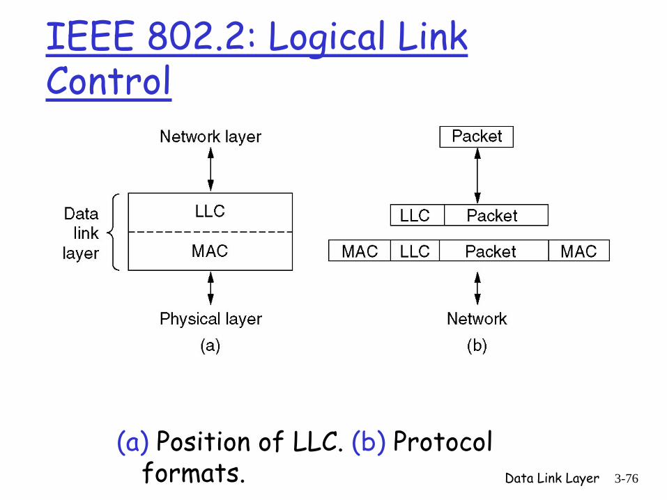
IEEE 802.2: Logical Link Control
(a) Position of LLC. (b) Protocol formats.

Data Link Layer 3-77
Broadcast Domain
A single Ethernet is associated with a broadcast domain.
All stations in a broadcast domain can “see” all traffic sent to/from other stations:
• Unicast addresses• Broadcast address (all 1’s)• A fixed set of multicast addresses (leading “1”)
An adapter usually forwards to its host only traffic addressed to it (or broadcast)
• May be set to operate in “promiscuous” mode.

Data Link Layer 3-78
Ethernet Transmission Algorithm
Adaptor senses the channel. If idle, it transmits immediately (max of 1500 bytes of data). If additional station(s) transmit before first adaptor completes, there will be a “collision.” A station listens for collision during the time that it transmits. To detect worse-case collision, it must transmit until its signal can reach the furthest station and return (approximately twice prop delay).

Data Link Layer 3-79
Ethernet MAC Sublayer Protocol (2)
Collision detection can take as long as 2 .τ

Data Link Layer 3-80
Minimum Frame Size
To insure collision is detected min frame length must be twice the LAN latency plus repeater time (4 repeaters max and max LAN of 2500 m).
Amounts to , which corresponds to 512 bits on 10 mbps Ethernet.Thus minimum frame size is 64 bytes
• 14 bytes header, 46 bytes data, 4 bytes CRC.
51.2 secμ
Data Link Layer 3-81
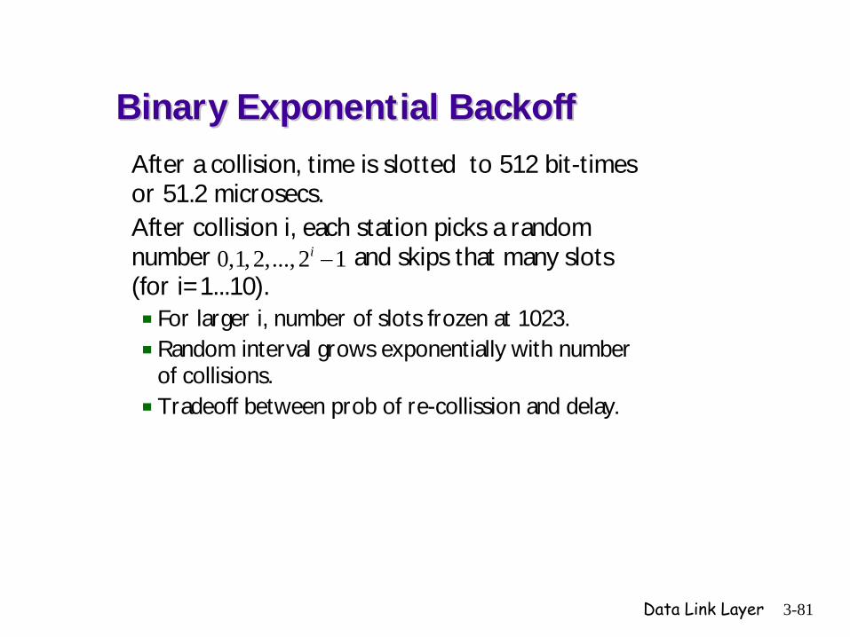
Binary Exponential BackoffBinary Exponential BackoffAfter a collision, time is slotted to 512 bit-times or 51.2 microsecs.After collision i, each station picks a random number and skips that many slots (for i=1...10).
For larger i, number of slots frozen at 1023.Random interval grows exponentially with number of collisions.Tradeoff between prob of re-collission and delay.
0,1,2,..., 2 1i −

Data Link Layer 3-82
Approximate Ethernet PerformanceFor heavy load case: Assume there are k stations on the LAN and that each is always ready to transmsit. We will NOT analyze the binaryexponential backoff algorithm. Instead, assume there is a constanttransmission probability in each slot (first attempt or re-attempt).Note that time is slotted after a collision. Suppose that each stationtransmits during a given slot is always . Then the probap
( )k 11
2
bility thatexactly one station acquires the channel (only station to transmit) is
( ) = (1 ) , a binomial probability. Take the derivative and
1'( ) (1 ) (1 ). Thus, is the value tha
k
k
s p p p
s p k p kp pk
−
−
−
= − − = t maximizes
the probability of successful transmission.

Data Link Layer 3-83
Ethernet Performance (continued)1 k-1
k
k-1
1 1Notice that lim ( ) lim (1 ) lim (1 ) , when p= .k
1(1 )1 1Also, lim (1 ) lim lim(1 ) . Now let 1(1 )
1lim ( )= lim(1 ) and it follows that lim ln( ) lim ln(
k
k k k
k
k k k
k
k k k k
s p kp pk
kk k
k
f k f kk
−
→∞ →∞ →∞
→∞ →∞ →∞
→∞ →∞ →∞ →∞
= − = −
−− = = −
−
− =
2
2
1
1
1
1 1
1
11 )
1ln(1 ) 0lim , which is a case that can be evaluated using 0
1 1L'Hospital's rule. Thus, this limit equals lim lim 1.1
Because lim ln( ) 1, We know lim ( ) . T
kk
k
k
k kkk
k k
k
k
f f k e
→∞
→∞ →∞
−
→∞ →∞
−
−=
−= − = −
− −
= − = hus, holding
1 1, we have lim , where is the probability of success for each slot.k
p s sk e→∞
= =

Data Link Layer 3-84
Ethernet Performance Continued
1
The probability that success occurs on the slot is the geometric probability (1 ) and we've seen that the expected number of attempts
1for success in a geometric distribution is which equals
j
jths s
s
−−
in this case.
Thus, the average waiting time between the end of one transmission and start of the next is 51.2 sec ( times slot length). If the average
transmission time is T sec , then approxima
e
e eμ
μ
×
Tte channel efficiency is .T 51.2e+
Ref: Metcalfe and Boggs: Ethernet: Distributed Packet Switching for Local Computer Networks, Comm of the ACM, vol. 19, July 1976.

Data Link Layer 3-85
Ethernet PerformanceEfficiency of Ethernet at 10 Mbps with 512-
bit slot times.

Data Link Layer 3-86
Non-persistent and p-persistent CSMANon-persistent and p-persistent CSMA
Non-persistentstation senses the channel and transmits if idle.if NOT idle, then waits a random time before sensing again.
p-persistentassumes slotted channelstation senses the channel and, if idle, transmits with prob p. With prob 1-p waits to next slot, senses again and makes same decision.if NOT idle, then senses the next slot until idle and repeats the p & 1-p decision above.if transmits and collision occurs, backs off random timeif, after senses idle, another station begins transmitting behaves as though collision had occurred.

Data Link Layer 3-87
Channel Utilization versus Load for Random Access ProtocolsChannel Utilization versus Load for Random Access Protocols

Data Link Layer 3-88
802.4: Token Bus802.4: Token Bus802.3 most widely used office LANMany businesses concerned about potential for unbounded delay on Ethernet.General Motors drove new standard based on passing a "token"Token bus supporters concerned about reliability of token ring so supported token bus: an arbitrary linear or tree topology.

Data Link Layer 3-89
Token Bus (continued)Token Bus (continued)Stations uniquely numbered highest to lowest and token passes accordingly.
Physical location not importantBroadcast domain so everyone "hears."75 Ohm cable with speeds of 1, 5, 10 Mbps possible.Four priority classes for traffic: 6, 4, 3, 0 (hi->low)
Significant advantage over EthernetExample: 50 stations on 10Mbps network with 3.333Mbps dedicated to priority 6 traffic. Implies each station gets 3.333x10⁶/50 = 67kbps (approx) guaranteed for priority 6. Enough to support voice.

Data Link Layer 3-90
Token Ring: 802.5Token Ring: 802.5
Also passes token (like token bus)Station removes token (by flipping bit) before transmitting.Note 1-bit delay.
4 or 16MbpsOne Bit-distance is either
Topology Listen Mode Transmit Mode
6 6meters meterssec secmeters meters
bit bit6 6bits bitssec sec
200 10 200 1050 or 12.5 , which implies4 10 16 10
that 1,000 meter ring can hold 20 or 80 bits.
× ×= =
× ×

Data Link Layer 3-91
Token Ring Media Access Control
Network adapter has receiver, transmitter and one (more) bit of storage.Token circulates if no station has data to transmit.Ring must hold an entire token. TR monitor adds additional bits of delay if needed. When station has data to send it “seizes” the token by flipping one bit in the 2nd byte of the token (converts it to preamble for next frame).

Data Link Layer 3-92
Token Ring (continued)Token Ring (continued)Station gets token, sends frame, removes frame from ring (as bits propagate around the ring and return), then regenerates token and goes to listen mode.Max frame size in practice is 2000 bytesIf no traffic to send, station simply passes token along.Under heavy load channel utilization can approach 100%.Virtually all installations use star-wired hubs as below.

Data Link Layer 3-93
Fiber Distributed Data Interface (FDDI)Fiber Distributed Data Interface (FDDI)
Fiber Optic token ring at 100Mbps up to 200km with up to 1000 stations connected.Commonly used as backbone to interconnect lower-speed LANs. Multimode fiber with LEDs...1 error in 2.5x1010 bits.Two counter-rotating rings, reconfigure to single ring on break.Mac protocol similar to 802.5 (token ring)
Also permits synchronous frames for voice circuits (up to 4T1 channels supported per frame).Synch frames have priority over asynch

Data Link Layer 3-94
Plaza Coliseum
Bates
Wardlaw Coker
Currell
Humanities
LeConte
BA
7513
CSD Annex
InfoAve
BBN Planet
AGS+ Router
Ethernet Token Ring Fiber
LEGEND
IBM Server
USC FDDI BackboneUSC FDDI Backbone
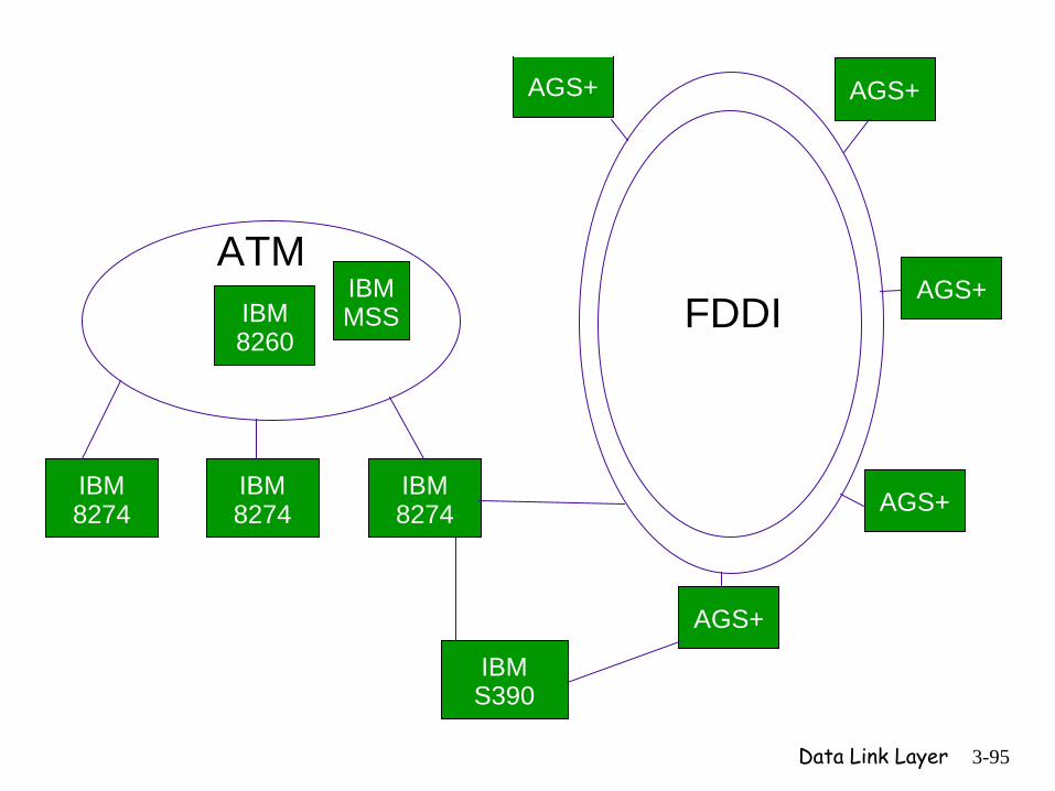
Data Link Layer 3-95
AGS+
AGS+
AGS+
AGS+AGS+
IBM 8274
IBM 8274
IBM 8274
FDDIIBM 8260
ATMIBM MSS
IBM S390

Data Link Layer 3-96
Architecture of Network AdapterPrincipal components: I/O Bus, Bus interface, Network Link, Link Interface
I/O Bus probably parallel & may run at 1Gbps or faster.Ethernet may be implemented in chipset on the link adapter. Alternative is software implementation on microprocessor or FPGA. Some buffering needed between the two interfaces.
BusInterface
LinkInterface
NetworkLink

Data Link Layer 3-97
Architecture Concepts
CPU communicates with adaptor using Control Status Register (xmit,rx,status)Adaptor interrupts the host when host intervention required and CPU runs interrupt handler.Frame bytes are transferred to/from memory using either PIO or DMA.
PIO implies CPU must do the work.DMA implies adapter reads/writes directly from host memory.

Data Link Layer 3-98
Memory Bottleneck Example

Data Link Layer 3-99
Memory and Performance
Host performance depends onActual I/O bus speed as opposed to advertised max.E.G. 8-cycles required to acquire I/O bus implies time to transfer 64-byte packet is 8 cycles plus 16 cycles (4 bytes transferred per cycle if bus is 32 bits wide)= 24 cycles.
• 24 cycles at 33 MHz is 0.727 microsecs and 64 bytes per 0.727 microsec is 704 Mbps NOT 1 Gbps.
Also, memory-cpu path may be crossed multiple times reducing by this factor.
• Remember higher layers also

Data Link Layer 3-100
Data Link Layer Switching
• Bridges from 802.x to 802.y• Local Internetworking• Spanning Tree Bridges• Remote Bridges• Repeaters, Hubs, Bridges, Switches,
Routers, Gateways• Virtual LANs

Data Link Layer 3-101
Data Link Layer SwitchingMultiple LANs connected by a backbone to handle a total load higher than the capacity
of a single LAN.

Data Link Layer 3-102
Bridges from 802.x to 802.yOperation of a LAN bridge from 802.11 to
802.3.

Data Link Layer 3-103
Local Internetworking
A configuration with four LANs and two bridges.

Data Link Layer 3-104
Spanning Tree Bridges
Two parallel transparent bridges.

Data Link Layer 3-105
Spanning Tree Bridges (2)
(a) Interconnected LANs. (b) A spanning tree covering the LANs. The dotted lines are not part of the spanning tree.

Data Link Layer 3-106
Remote Bridges
Remote bridges can be used to interconnect distant LANs.

Data Link Layer 3-107
Repeaters, Hubs, Bridges, Switches, Routers and Gateways
(a) Which device is in which layer.(b) Frames, packets, and headers.

Data Link Layer 3-108
Repeaters, Hubs, Bridges, Switches, Routers and Gateways (2)(a) A hub. (b) A bridge. (c) a switch.
Data Link Layer 3-109
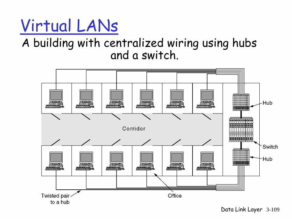
Virtual LANsA building with centralized wiring using hubs
and a switch.

Data Link Layer 3-110
Virtual LANs (2)
(a) Four physical LANs organized into two VLANs, gray and white, by two bridges. (b) The same 15 machines organized into two VLANs by switches.