data link installation manual -...
TRANSCRIPT

190-00837-00 August, 2010 Revision C
GDL 59 Data Link Installation Manual

Page A GDL 59 Installation Manual Revision C 190-00837-00
© Copyright 2010
Garmin Ltd. or its subsidiaries
All Rights Reserved
Except as expressly provided herein, no part of this manual may be reproduced, copied, transmitted, disseminated, downloaded or stored in any storage medium, for any purpose without the express prior written consent of Garmin. Garmin hereby grants permission to download a single copy of this manual and of any revision to this manual onto a hard drive or other electronic storage medium to be viewed and to print one copy of this manual or of any revision hereto, provided that such electronic or printed copy of this manual or revision must contain the complete text of this copyright notice and provided further that any unauthorized commercial distribution of this manual or any revision hereto is strictly prohibited.
Garmin International, Inc. 1200 E. 151st Street
Olathe, KS 66062 USA Telephone: 913.397.8200
Aviation Panel-Mount Technical Support Line (Toll Free) 1.888.606.5482 www.garmin.com
Garmin (Europe) Ltd. Liberty House, Bulls Copse Road
Hounsdown Business Park Southampton, SO40 9RB U.K.
+44/ (0) 870.8501241
Garmin AT, Inc. 2345 Turner Rd., SE
Salem, OR 97302 USA Telephone: 503.581.8101
RECORD OF REVISIONS
Revision Revision Date Description A 04/09/08 Initial Release B 07/06/09 Corrrected interconnect drawing and added ETSO info C 08/17/10 Added Flight Data Services activation information
DOCUMENT PAGINATION
Section Page Range Table of Contents i–iv
Section 1 1-1–1-8 Section 2 2-1–2-2 Section 3 3-1–3-6 Section 4 4-1–4-6
Appendix A A-1–A-8 Appendix B B-1–B-2
GDL 59 Installation Manual Page i 190-00837-00 Revision C
INFORMATION SUBJECT TO EXPORT CONTROL LAWS
This document may contain information which is subject to the Export Administration Regulations ("EAR") issued by the United States Department of Commerce (15 CFR, Chapter VII, Subchapter C) and which may not be exported, released, or disclosed to foreign nationals inside or outside of the United States without first obtaining an export license. The preceding statement is required to be included on any and all reproductions in whole or in part of this manual.
WARNING
This product, its packaging, and its components contain chemicals known to the State of California to cause cancer, birth defects, or reproductive harm. This Notice is being provided in accordance with California's Proposition 65. If you have any questions or would like additional information, please refer to our web site at www.garmin.com/prop65.
WARNING
Perchlorate Material – special handling may apply, See www.dtsc.ca.gov./hazardouswaste/perchlorate.
CURRENT REVISION DESCRIPTION
Revision Page
Number(s) Section Number
Description of Change
1-5 1.4.5 Added new Wi-Fi info 1-7 1.5.3 Added 802.11 info to Table 1-9 C 3-6 3.8 Added Flight Data Services activation info

Page ii GDL 59 Installation Manual Revision C 190-00837-00
TABLE OF CONTENTS PARAGRAPH PAGE 1. GENERAL DESCRIPTION 1-1 1.1 Introduction........................................................................................................................................1-1 1.2 Equipment Description ......................................................................................................................1-1 1.3 Interface Summary.............................................................................................................................1-2 1.4 Technical Specifications ....................................................................................................................1-3 1.5 Certification .......................................................................................................................................1-5 1.6 Reference Documentation..................................................................................................................1-7 1.7 Limited Warranty...............................................................................................................................1-8 2. INSTALLATION 2-1 2.1 Introduction........................................................................................................................................2-1 2.2 Installation Materials .........................................................................................................................2-1 2.3 Equipment Available .........................................................................................................................2-1 2.4 Cabling and Wiring............................................................................................................................2-1 2.5 Cooling Air ........................................................................................................................................2-2 2.6 Mounting Requirements ....................................................................................................................2-2 3. INSTALLATION PROCEDURE 3-1 3.1 Unpacking Unit..................................................................................................................................3-1 3.2 Wiring Harness Installation ...............................................................................................................3-1 3.3 Wi-Fi Antenna Installation ................................................................................................................3-2 3.4 Coaxial Cable Installation..................................................................................................................3-4 3.5 Backshell Assembly and Installation .................................................................................................3-5 3.6 Final Installation ................................................................................................................................3-5 3.7 Post Installation Configuration and Checkout ...................................................................................3-6 3.8 Activation of Garmin Flight Data Services .......................................................................................3-6 3.9 Continued Airworthiness ...................................................................................................................3-6 4. SYSTEM INTERCONNECTS 4-1 4.1 Pin Function List................................................................................................................................4-1 4.2 Power Functions ................................................................................................................................4-3 4.3 Installation Selection Pins..................................................................................................................4-3 4.4 Serial Data .........................................................................................................................................4-4 4.5 Audio Connections ............................................................................................................................4-6 APPENDIX A OUTLINE AND INSTALLATION DRAWINGS APPENDIX B INTERCONNECT DRAWING

GDL 59 Installation Manual Page iii 190-00837-00 Revision C
LIST OF ILLUSTRATIONS FIGURE PAGE 1-1 GDL 59 Unit View ............................................................................................................................1-1 1-2 GDL 59 Block Diagram.....................................................................................................................1-2 2-1 GDL 59 Modular Unit Rack ..............................................................................................................2-2 3-1 TNC Connector Installation...............................................................................................................3-4 A-1 GDL 59 Modular Rack Outline Drawing (Sheet 1 of 2)...................................................................A-1 A-1 GDL 59 Modular Rack Outline Drawing (Sheet 2)..........................................................................A-3 A-2 GDL 59 Stand-alone Rack Outline Drawing (Sheet 1 of 2) .............................................................A-5 A-2 GDL 59 Stand-alone Rack Outline Drawing (Sheet 2) ....................................................................A-7 B-1 GDL 59 Example Interconnect ......................................................................................................... B-1
LIST OF TABLES
TABLE PAGE 1-1 Unit with Modular Rack ....................................................................................................................1-3 1-2 Unit with Stand-alone Rack...............................................................................................................1-4 1-3 Input Voltage .....................................................................................................................................1-4 1-4 Maximum Current Specifications ......................................................................................................1-4 1-5 General Specifications .......................................................................................................................1-4 1-6 Wi-Fi Antenna Minimum Requirements ...........................................................................................1-5 1-7 TSO/ETSO Authorizations ................................................................................................................1-6 1-8 TSO/ETSO Deviations ......................................................................................................................1-6 1-9 Non-TSO Functions...........................................................................................................................1-7 1-10 Referenced Publications ....................................................................................................................1-7 2-1 Unit Part Number...............................................................................................................................2-1 2-2 Accessories ........................................................................................................................................2-1 3-1 Pin Contact Part Numbers..................................................................................................................3-1 3-2 Recommended Crimp Tools ..............................................................................................................3-1

Page iv GDL 59 Installation Manual Revision C 190-00837-00
GDL 59 HARDWARE MOD LEVEL HISTORY The following table identifies hardware modification (Mod) Levels for the GDL 59. Mod Levels are listed with the associated service bulletin number, service bulletin date, and the purpose of the modification. The table is current at the time of publication of this manual (see date on front cover) and is subject to change without notice. Authorized Garmin Sales and Service Centers are encouraged to access the most up-to-date bulletin and advisory information on the Garmin Dealer Resource web site at www.garmin.com using their Garmin-provided user name and password.
MOD LEVEL
SERVICE BULLETIN NUMBER
SERVICE BULLETIN
DATE
PURPOSE OF MODIFICATION

GDL 59 Installation Manual Page 1-1 190-00837-00 Revision C
1 GENERAL DESCRIPTION
1.1 Introduction
This manual presents mechanical and electrical installation requirements for installing the GDL 59 as part of the Garmin Integrated Flight Deck. The GDL 59 can be integrated into a variety of airframes under an appropriate TC or STC. Each installation may vary. Use only approved (type or supplemental type) data for specific installation instructions in a particular aircraft.
Figure 1-1. GDL 59 Unit View
1.2 Equipment Description
The GDL 59 provides a POTS (plain old telephone service) phone interface, a flight parameter data logger, and a high speed data link between the aircraft systems and ground computers while the aircraft is on the ground using the IEEE 802.11g (“Wi-Fi”) protocol. The GDL 59 also provides two interfaces to an optional GSR 56, which adds airborne low speed data link and voice communication capability.

Page 1-2 GDL 59 Installation Manual Revision C 190-00837-00
1.3 Interface Summary
The GDL 59 unit interfaces to the Garmin Integrated Flight Deck using HSDB. The GDL 59 can be installed with zero, one, or two GSR 56 units. Installation will vary between airframes.
Passenger Computers
Handset
Other Avionics
Iridium
RS-232Ethernet
Ethernet
Ethernet
WiFi
GDL 59
GSR 56 (Optional)
GSR 56 (Optional)
Iridium
Iridium Audio
GDU 1XXX (or GDL 69Aor GSD 41)
POTS
Audio Panel(s)
RS-232
Iridium Audio
HSDB
HSDB
Audio
Figure 1-2. GDL 59 Block Diagram

GDL 59 Installation Manual Page 1-3 190-00837-00 Revision C
1.3.1 I/O
The GDL 59 supports the following I/O: • Audio Panel I/O: The GDL 59 provides one differential audio I/O channel for interfacing to the
audio panel(s).
• Avionics HSDB: The GDL 59 provides two HSDB ports. One port must be used to connect the GDL 59 to the core Garmin Integrated Flight Deck system via a spare GDU 1XXX, GSD 41, or GDL 69A HSDB port. The other port is available for possible future avionics expansion.
• Iridium Audio I/O: The GDL 59 provides two differential audio I/O channels to carry Iridium telephone audio to and from the GSR 56 Iridium transceiver(s).
• Analog POTS Interface: The GDL 59 provides a POTS (plain old telephone service) interface that allows a standard analog telephone to interface to the GDL 59. Up to two POTS telephones can be connected to this interface in parallel.
NOTE
To simplify operation of the telephone, Garmin recommends using a POTS telephone that does not have a Hold button.
• RS-232 I/O: The GDL 59 has two RS-232 ports. RS-232 is the primary communication path between the GDL 59 and the GSR 56 units.
• Ethernet Ports: The GDL 59 provides three 10/100 Base T Ethernet ports that are compliant with IEEE 802.3 standards. These ports can be used to provide connection to an Electronic Flight Bag (EFB), or for other future options.
1.4 Technical Specifications
It is the responsibility of the installing agency to obtain the latest revision of the GDL 59 Environmental Qualification Form. This form is available directly from Garmin under the following part number:
GDL 59 Environmental Qualification Form, Garmin part number 005-00431-10
To obtain a copy of this form, see the dealer/OEM portion of the Garmin web site (www.garmin.com).
1.4.1 Physical Characteristics
Table 1-1. Unit with Modular Rack
Characteristic Specification
Width 1.23 inches (3.12 cm) Height 6.30 inches (16.00 cm) Depth (Rack w/ Connectors) 9.07 inches (23.04 cm) Unit Weight (GDL 59) 1.5 lb (0.68 kg) Unit (GDL 59) and Modular Rack Weight 2.3 lb (1.04 kg)
Page 1-4 GDL 59 Installation Manual Revision C 190-00837-00
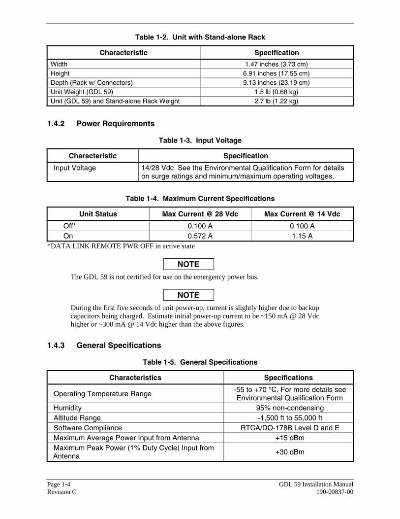
Table 1-2. Unit with Stand-alone Rack
Characteristic Specification
Width 1.47 inches (3.73 cm) Height 6.91 inches (17.55 cm) Depth (Rack w/ Connectors) 9.13 inches (23.19 cm) Unit Weight (GDL 59) 1.5 lb (0.68 kg) Unit (GDL 59) and Stand-alone Rack Weight 2.7 lb (1.22 kg)
1.4.2 Power Requirements
Table 1-3. Input Voltage
Characteristic Specification
Input Voltage 14/28 Vdc See the Environmental Qualification Form for details on surge ratings and minimum/maximum operating voltages.
Table 1-4. Maximum Current Specifications
Unit Status Max Current @ 28 Vdc Max Current @ 14 Vdc
Off* 0.100 A 0.100 A On 0.572 A 1.15 A
*DATA LINK REMOTE PWR OFF in active state
NOTE
The GDL 59 is not certified for use on the emergency power bus.
NOTE
During the first five seconds of unit power-up, current is slightly higher due to backup capacitors being charged. Estimate initial power-up current to be ~150 mA @ 28 Vdc higher or ~300 mA @ 14 Vdc higher than the above figures.
1.4.3 General Specifications
Table 1-5. General Specifications
Characteristics Specifications
Operating Temperature Range -55 to +70 °C. For more details see Environmental Qualification Form
Humidity 95% non-condensing Altitude Range -1,500 ft to 55,000 ft Software Compliance RTCA/DO-178B Level D and E Maximum Average Power Input from Antenna +15 dBm Maximum Peak Power (1% Duty Cycle) Input from Antenna +30 dBm

GDL 59 Installation Manual Page 1-5 190-00837-00 Revision C
1.4.4 General Antenna Requirements
Garmin recommends the Wi-Fi antenna specifications shown in Table 1-6. These antenna specifications are approved with the certification of the GDL 59. Any Wi-Fi antenna with specifications listed in the following table should work with the GDL 59.
Table 1-6. Wi-Fi Antenna Minimum Requirements
Characteristics Specifications
Frequency Range 2412 to 2484 MHz Gain (Typical) <5 dB* Nominal Output Impedance 50 ohms Operating Temperature Gain -50 to +85°C**
*For each 1 dB gain over 5 dB, add 1 dB of attenuation into the antenna cable path between the antenna and the GDL 59. **STC/Installation dependent
1.4.5 Wi-Fi Network Requirements
To ensure compatibility with the GDL 59, the Wi-Fi network must comply with the below requirements. • Fully IEEE 802.11g compatible
• All access points must be coupled to a DHCP server
• The network shall support data transfer via HTTP and HTTPS and allow outgoing connections to the internet on port 80 and port 443
• Networks that include web proxies, captive portals, or other elements that require user credentials, including a username and password or a redemption or access code; or require action such as accepting a user agreement, are not supported for data transfer from the GDL 59
• The access point must be capable of receiving at a rate of 18 Mbps
• The Wi-Fi network shall be compatible with WEP64, WEP128,WPA-PSK, or WPA2-PSK encryption formats, and with all of those formats associated encryption combinations and options; or compatible to be used with no encryption. WPA-Enterprise and WPA2-Enterprise are not supported
• If WPA-PSK or WPA2-PSK are used, the access point must not be set to auto-select between them.
1.5 Certification
The conditions and tests required for the TSO approval of this article are minimum performance standards. It is the responsibility of those installing this article either on or within a specific type or class of aircraft to determine that the aircraft installation conditions are within the TSO standards. TSO articles must have separate approval installation in an aircraft. The article may be installed only if performed under 14 CFR part 43 or the applicable airworthiness requirements.
The GDL 59 system is limited to communication to the cockpit and cabin for convenience only.

Page 1-6 GDL 59 Installation Manual Revision C 190-00837-00
1.5.1 TSO/ETSO Compliance
The GDL 59 shall carry the TSO/ETSO authorizations listed in Table 1-7.
Table 1-7. TSO/ETSO Authorizations
Function TSO/ETSO Applicable LRU Software Part
Numbers
Aircraft Audio Systems and Equipment TSO-C139
006-B0735-1( ) 006-B0736-1( ) 006-D1112-1( ) 006-D1232-1( )
Audio Selector Panels and Amplifier ETSO-C50c
006-B0735-1( ) 006-B0736-1( ) 006-D1112-1( ) 006-D1232-1( )
1.5.2 TSO/ETSO Deviations
The GDL 59 shall carry the TSO/ETSO deviations listed in Table 1-8.
Table 1-8. TSO/ETSO Deviations
TSO/ETSO Deviation
1. Garmin was granted a deviation from TSO-C139 subpart 3b to consider failure of the intended function of the GDL59, defined in the stated paragraph of TSO-C139, as minor. 2. Garmin was granted a deviation from TSO-C139 to use the environmental qualification form as part of RTCA DO-160E instead of the form required as part of DO-160D. 3. Garmin was granted a deviation from TSO-C139 subpart 7a which requires furnishing each person receiving a GDL 59 copy of the data listed in paragraph 5l of TSO-C139.
TSO-C139
4. Garmin was granted a deviation from TSO-C139 subpart 7b which requires furnishing each person receiving a GDL 59 a copy of the data in paragraphs 5l, 5m, and 5n of TSO-C139. 1. Garmin was granted a deviation from ETSO-C50c § 3.1.2 to use EUROCAE ED-14E/ RTCA DO-160E instead of ED-14D/ RTCA DO-160D as the environmental test standard.
ETSO-C50c 2. Garmin was granted a deviation from ETSO-C50c § 3.1.1 to use RTCA DO-214 instead of EUROCAE ED-18/RTCA DO-170 as the Minimum Performance Standard.

GDL 59 Installation Manual Page 1-7 190-00837-00 Revision C
1.5.3 Non-TSO Functions
The non-TSO functions listed in Table 1-9 were tested to RTCA/DO-160E environmental qualifications.
Table 1-9. Non-TSO Functions
Function Design Assurance Applicable LRU Software Part Numbers
802.11 Radio Data Link RTCA/DO-178B Level E 006-B0736-1() 006-D1112-1()
802.11 Radio Data Link RTCA/DO-178B Level D 006-B0735-1() 006-D1232-1()
Data Link Radio Controller RTCA/DO-178B Level E 006-B0736-1() 006-D1112-1()
Data Link Radio Controller RTCA/DO-178B Level D 006-B0735-1() 006-D1232-1()
Flight Data Logger RTCA/DO-178B Level D 006-B0735-1() 006-D1232-1()
1.6 Reference Documentation
The publications listed in Table 1-10 are sources of additional information for installing the GDL 59. Before installing the GDL 59, the technician should read all referenced materials applicable to the installation along with this manual.
Table 1-10. Referenced Publications
Part Number Document
005-00431-10 GDL 59 Environmental Qualification Form 190-00303-00 G1000 System Installation Manual 190-00303-04 G1000 Line Maintenance and Configuration Manual

Page 1-8 GDL 59 Installation Manual Revision C 190-00837-00
1.7 Limited Warranty
This Garmin product is warranted to be free from defects in materials or workmanship for two years from the date of purchase. Within this period, Garmin will at its sole option, repair or replace any components that fail in normal use. Such repairs or replacement will be made at no charge to the customer for parts or labor, provided that the customer shall be responsible for any transportation cost. This warranty does not cover failures due to abuse, misuse, accident or unauthorized alteration or repairs.
THE WARRANTIES AND REMEDIES CONTAINED HEREIN ARE EXCLUSIVE AND IN LIEU OF ALL OTHER WARRANTIES EXPRESS OR IMPLIED OR STATUTORY, INCLUDING ANY LIABILITY ARISING UNDER ANY WARRANTY OF MERCHANTABILITY OR FITNESS FOR A PARTICULAR PURPOSE, STATUTORY OR OTHERWISE. THIS WARRANTY GIVES YOU SPECIFIC LEGAL RIGHTS, WHICH MAY VARY FROM STATE TO STATE.
IN NO EVENT SHALL GARMIN BE LIABLE FOR ANY INCIDENTAL, SPECIAL, INDIRECT OR CONSEQUENTIAL DAMAGES, WHETHER RESULTING FROM THE USE, MISUSE, OR INABILITY TO USE THIS PRODUCT OR FROM DEFECTS IN THE PRODUCT. Some states do not allow the exclusion of incidental or consequential damages, so the above limitations may not apply to you.
Garmin retains the exclusive right to repair or replace the unit or software or offer a full refund of the purchase price at its sole discretion. SUCH REMEDY SHALL BE YOUR SOLE AND EXCLUSIVE REMEDY FOR ANY BREACH OF WARRANTY.
To obtain warranty service, contact your local Garmin Authorized Service Center. For assistance in locating a Service Center near you, call Garmin Customer Service at one of the numbers shown below.
Products sold through online auctions are not eligible for rebates or other special offers from Garmin. Online auction confirmations are not accepted for warranty verification. To obtain warranty service, an original or copy of the sales receipt from the original retailer is required. Garmin will not replace missing components from any package purchased through an online auction.
Garmin International, Inc. Garmin (Europe) Ltd. 1200 East 151st Street Liberty House, Bulls Copse Road Olathe, Kansas 66062, U.S.A. Hounsdown Business Park Phone: 913/397.8200 Romsey, SO40 9RB, U.K.
FAX: 913/397.0836 Phone: +44/ (0) 870.8501241 FAX: +44/ (0) 870.8501251

GDL 59 Installation Manual Page 2-1 190-00837-00 Revision C
2 INSTALLATION
2.1 Introduction
This section provides hardware equipment information for installing the GDL59 and related hardware. Installation of the GDL 59 should follow the aircraft TC or STC requirements. Cabling is fabricated by the installing agency to fit each particular aircraft. The guidance of FAA advisory circulars AC 43.13-1B and AC 43.13-2A, where applicable, may be found useful for making retro-fit installations that comply with FAA regulations.
Refer to the G1000 System Installation Manual, Garmin part number 190-00303-00 for further details on the mechanical aspects.
2.2 Installation Materials
The GDL 59 is available only as a single unit under the following part number:
Table 2-1. Unit Part Number
Item Garmin Catalog Part Number
GDL 59 Unit (011-01746-00) 010-00666-00
2.3 Equipment Available
Each of the following accessories are provided separately for the GDL 59.
Table 2-2. Accessories
Item Garmin Catalog Part Number
GDL 59 Unit Rack, Modular 115-00411-00 (preferred) GDL 59 Unit Rack, Stand-alone 115-00658-00
G1000 Rack Nutplate Kit 011-00915-00 (preferred) or
011-01148-00 GDL 59 Back Plate (‘C’ Keyplate) 011-00796-02 GDL 59 Connector Kit 011-01760-00
2.4 Cabling and Wiring
Use AWG #24 or larger wire for all connections unless otherwise specified by the aircraft manufacturer or Garmin. The standard pin contacts supplied in the connector kit are compatible with up to AWG #22 wire. In cases where some installations have more than one unit sharing a common circuit breaker, sizing and wire gauge is based on aircraft circuit breaker layout, length of wiring, current draw of units, and internal unit protection characteristics. Do not attempt to combine more than one unit on the same circuit breaker unless it is specified on aircraft manufacturer approved drawings.
In some cases, a larger gauge wire such as AWG #16, #18, or #20 may be needed for power connections. Special thin-wall heat shrink tubing is also provided to insulate the extended barrels inside the backshell. If using #16 or #18 barrel contacts, ensure that no two contacts are mounted directly adjacent to each other. This minimizes the risk of contacts touching and shorting to adjacent pins and to ground.
Page 2-2 GDL59 Installation Manual Revision C 190-00837-00
Ensure that routing of the wiring does not come in contact with sources of heat or RF/EMI interference. Check that there is ample space for the cabling and mating connectors. Avoid sharp bends in cabling and routing near aircraft control cables.
2.5 Cooling Air
No cooling air is needed for the GDL 59.
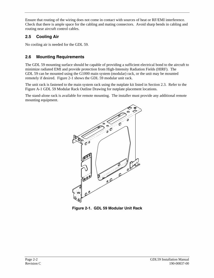
2.6 Mounting Requirements
The GDL 59 mounting surface should be capable of providing a sufficient electrical bond to the aircraft to minimize radiated EMI and provide protection from High-Intensity Radiation Fields (HIRF). The GDL 59 can be mounted using the G1000 main system (modular) rack, or the unit may be mounted remotely if desired. Figure 2-1 shows the GDL 59 modular unit rack.
The unit rack is fastened to the main system rack using the nutplate kit listed in Section 2.3. Refer to the Figure A-1 GDL 59 Modular Rack Outline Drawing for nutplate placement locations.
The stand-alone rack is available for remote mounting. The installer must provide any additional remote mounting equipment.
Figure 2-1. GDL 59 Modular Unit Rack

GDL 59 Installation Manual Page 3-1 190-00837-00 Revision C
3 INSTALLATION PROCEDURE
3.1 Unpacking Unit
Carefully unpack the equipment and make a visual inspection of the unit for evidence of damage incurred during shipment. If the unit is damaged, notify the carrier and file a claim. To justify a claim, save the original shipping container and all packing materials. Do not return the unit to Garmin until the carrier has authorized the claim.
Retain the original shipping containers for storage. If the original containers are not available, a separate cardboard container should be prepared that is large enough to accommodate sufficient packing material to prevent movement.
3.2 Wiring Harness Installation
Allow adequate space for installation of cables and connectors. The installer shall supply and fabricate all of the cables. Electrical connections are made through a 78-pin D-Subminiature connector and a TNC coaxial connector.
Section 4 defines the electrical characteristics of all input and output signals. Required connectors and associated hardware are supplied with the connector kit (refer to Section 2.3). See Appendix B for examples of interconnect wiring diagrams. Construct the actual harnesses in accordance with aircraft specific approved interconnect diagrams.
Table 3-1. Pin Contact Part Numbers
78 pin D-Subminiature connector (P591) Manufacturer 16 AWG
(Power and Power Ground Only)
18-20 AWG (Power and Power
Ground Only)
22-28 AWG
Garmin P/N 336-00044-01 336-00044-00 336-00021-00 Military P/N N/A N/A M39029/58-360 AMP N/A N/A 204370-2 Positronic N/A N/A MC8522D ITT Cannon N/A N/A 030-2042-000
Table 3-2. Recommended Crimp Tools
18-20 AWG 22-28 AWG Manufacturer Hand Crimping
Tool Positioner Insertion/
Extraction Tool (note 2)
Positioner Insertion/ Extraction
Tool Military P/N M22520/2-01 N/A M81969/1-04 M22520/2-09 M81969/1-04
Positronic 9507 9502-11 M81969/1-04 9502-4 M81969/1-04
ITT Cannon 995-0001-584 N/A N/A M22520/2-09 274-7048-000
AMP 601966-1 N/A 91067-1 601966-6 91067-1
Daniels AFM8 K774 M81969/1-04 K42 M81969/1-04
Astro 615717 N/A M81969/1-04 615725 M81969/1-04

Page 3-2 GDL 59 Installation Manual Revision C 190-00837-00
NOTE
1. Non-Garmin part numbers shown are not maintained by Garmin and consequently are subject to change without notice.
2. Extracting the #16, #18 and #20 contact requires that the expanded wire barrel be cut off from the contact. It may also be necessary to push the pin out from the face of the connector when using an extractor due to the absence of the wire. A new contact must be used when reassembling the connector.
3. For applications using 16 AWG wire, contact Garmin for information regarding connector crimp positioner tooling.
3.3 Wi-Fi Antenna Installation
For use with the GDL 59, Wi-Fi antennas have an operating within a frequency range of 2412-2484 MHz. Minimum antenna requirements are listed in Section 1.4.4.
NOTE
It is the installer’s responsibility to ensure that their choice of antenna meets FAA certification standards according to the specific installation. This installation manual suggests the antenna specifications listed in Section 1.4.4. Other antennas may be acceptable but their installation is not covered by this manual.
There are several critical factors to take into consideration before installing an antenna for the GDL 59, these factors are addressed in the following sections.
3.3.1 Antenna Mounting
For installation mounting of the Wi-Fi antenna, follow the manufacturer’s instructions and the instructions in this Section (Section 3.3). It is not required to mount the Wi-Fi antenna on the outside of the aircraft.
3.3.2 Antenna Grounding
NOTE
Improper grounding of the antenna can cause poor signal reception.
It is very important to have good conductivity between the coaxial shield and the ground plane. This is ensured when all the fasteners properly ground the antenna base to the skin of the aircraft. The resistance between the antenna and the skin of the aircraft should be less than 10 milliohms.

GDL 59 Installation Manual Page 3-3 190-00837-00 Revision C
3.3.3 Wi-Fi Antenna Location
Observe the following during the antenna installation:
1. Maintain approximately 3 feet from heater, ignition, autopilot, and other control surface actuators and motors. Maintain approximately 5 feet from fluorescent lamps, related ballast, air conditioners, blowers, strobe lights, and power supplies.
2. The minimum distances to be observed when selecting an antenna location are as follows:
• 1.5 inches from any passive (receive only) antenna such as GPS, XM, or another Wi-Fi. • 20 cm is maintained between the antenna and all persons in the aircraft. • 5 inches from a VHF active antenna such as COM or ACARS. • 5 inches from an active radar altimeter (4 GHz). • 12 inches from a UHF/Microwave transmitting antenna such as a transponder, DME, active
TCAS, UAT, SATCOM, or Flitephone. 3.3.4 Wi-Fi Antenna to Receiver Signal Requirements
Observe the following antenna requirements:
(1) Wi-Fi antenna maximum gain is 5 dB.
(2) Wi-Fi antenna must be omni-directional.
(3) The interconnect and antenna gain/loss component must be between +6dB and -4dB. If the interconnect and antenna gain/loss component is outside this range, additional gain or loss must be added between the antenna and the GDL 59 RF input.
(4) Antenna input cannot exceed Maximum Power Input levels listed in Section 1.4.3.

Page 3-4 GDL 59 Installation Manual Revision C 190-00837-00
3.4 Coaxial Cable Installation
1. Choose the correct coax: RG-400/U has good characteristics for loss, size, and flexibility.
NOTE
It is critical to the performance of the GDL 59 to keep the cable loss of the antenna cable to a minimum through the use of appropriate coax cable and proper connector installation.
2. Trim the coaxial cable to the desired length and install TNC connectors at each end per the cabling instructions listed in Figure 3-1. For routing convenience, one end of the coaxial run can be terminated prior to installation.
3. With the GDL 59 receiver and antenna installed, route and clamp the coaxial cable in position. Secure cable in accordance with AC 43.13-1B, Chapter 11.
Figure 3-1. TNC Connector Installation

GDL 59 Installation Manual Page 3-5 190-00837-00 Revision C
3.5 Backshell Assembly and Installation
The GDL 59 connector kit includes a Garmin backshell assembly. Garmin’s backshell also gives the installer the ability to easily terminate shield grounds at the backshell housing using the Shield Block method. To assemble the backshell refer to instructions provided in the G1000 System Installation Manual (190-00303-00) and Shield Block Installation Instructions (190-00313-09).
3.6 Final Installation
For final installation and assembly, refer to the outline and installation drawings shown in Appendix A of this manual.
1. Assemble the connector backshells as described in Section 3.5.
2. Connect both connectors to the rear plate using the screws provided in the connector kit.
3. Mount the unit rack to the main system rack or other suitable mounting location using the provided nutplates.
4. Assemble the rear plate into the GDL 59 unit rack.
5. Insert the GDL 59 into the rack, noting proper orientation as shown on the installation drawings in Appendix A.
CAUTION
Do not use excessive force when inserting the GDL 59 into the rack. This may cause damage to occur to the connectors, unit, and/or unit rack. If heavy resistance is felt during installation, stop! Remove the GDL 59 and identify the source of resistance. The rear plate is designed to float in the unit rack. Check to ensure the rear plate is not bound by the connector harness.
6. Lock the GDL 59 in place using the lever-locking handle. Fasten the handle to the GDL 59 body using the provided Phillips screw.
CAUTION
Start the handle screw into the hole carefully to avoid cross-threading. Do not apply torque in excess of 14 in-lbs to the handle screw. The application of torque exceeding 14 in-lbs to this screw will damage the LRU case and/or retaining hardware.
Page 3-6 GDL 59 Installation Manual Revision C 190-00837-00
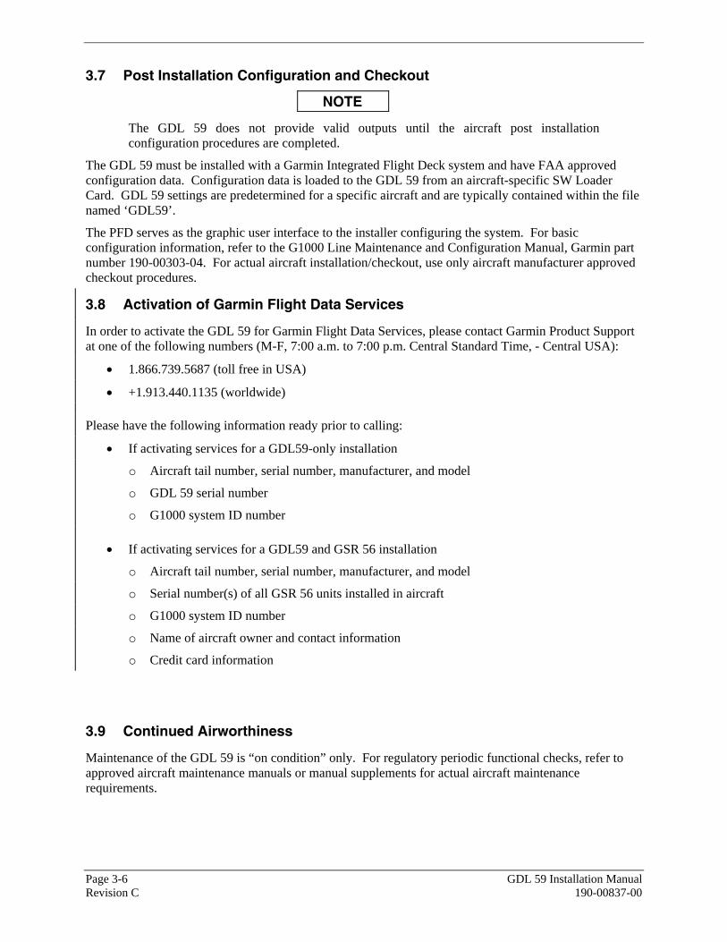
3.7 Post Installation Configuration and Checkout
NOTE
The GDL 59 does not provide valid outputs until the aircraft post installation configuration procedures are completed.
The GDL 59 must be installed with a Garmin Integrated Flight Deck system and have FAA approved configuration data. Configuration data is loaded to the GDL 59 from an aircraft-specific SW Loader Card. GDL 59 settings are predetermined for a specific aircraft and are typically contained within the file named ‘GDL59’.
The PFD serves as the graphic user interface to the installer configuring the system. For basic configuration information, refer to the G1000 Line Maintenance and Configuration Manual, Garmin part number 190-00303-04. For actual aircraft installation/checkout, use only aircraft manufacturer approved checkout procedures.
3.8 Activation of Garmin Flight Data Services
In order to activate the GDL 59 for Garmin Flight Data Services, please contact Garmin Product Support at one of the following numbers (M-F, 7:00 a.m. to 7:00 p.m. Central Standard Time, - Central USA):
• 1.866.739.5687 (toll free in USA)
• +1.913.440.1135 (worldwide)
Please have the following information ready prior to calling:
• If activating services for a GDL59-only installation
o Aircraft tail number, serial number, manufacturer, and model
o GDL 59 serial number
o G1000 system ID number
• If activating services for a GDL59 and GSR 56 installation
o Aircraft tail number, serial number, manufacturer, and model
o Serial number(s) of all GSR 56 units installed in aircraft
o G1000 system ID number
o Name of aircraft owner and contact information
o Credit card information
3.9 Continued Airworthiness
Maintenance of the GDL 59 is “on condition” only. For regulatory periodic functional checks, refer to approved aircraft maintenance manuals or manual supplements for actual aircraft maintenance requirements.

GDL 59 Installation Manual Page 4-1 190-00837-00 Revision C
4 SYSTEM INTERCONNECTS
4.1 Pin Function List
4.1.1 P591 Connector
View of J591 connector looking at rear of unit.
1 2 3 4 5 6 7 8 9 10 11 12 13 14 15 16 17 18 19 20
21 22 23 24 25 26 27 28 29 30 31 32 33 34 35 36 37 38 39
40 41 42 43 44 45 46 47 48 49 50 51 52 53 54 55 56 57 58 59
60 61 62 63 64 65 66 67 68 69 70 71 72 73 74 75 76 77 78
Pin Pin Name I/O 1 USER ETHERNET OUT 5 A Out 2 USER ETHERNET IN 5 A In 3 AVIONICS ETHERNET OUT 2 A Out 4 AVIONICS ETHERNET IN 2 A In 5 USER ETHERNET OUT 3 A Out 6 USER ETHERNET IN 3 A In 7 USER ETHERNET OUT 4 A Out 8 USER ETHERNET IN 4 A In 9 AVIONICS ETHERNET OUT 1 A Out 10 AVIONICS ETHERNET IN 1 A In 11 SIGNAL GROUND -- 12 SPARE -- 13 IRIDIUM AUDIO IN 2 HI In 14 IRIDIUM AUDIO OUT 2 HI Out 15 IRIDIUM AUDIO IN 1 HI In 16 IRIDIUM AUDIO OUT 1 HI Out 17 AUDIO SYSTEM 2 AUDIO IN HI In 18 AUDIO SYSTEM 2 AUDIO OUT HI Out 19 AUDIO SYSTEM 1 AUDIO IN HI In 20 AUDIO SYSTEM 1 AUDIO OUT HI Out 21 USER ETHERNET OUT 5 B Out 22 USER ETHERNET IN 5 B In 23 AVIONICS ETHERNET OUT 2 B Out 24 AVIONICS ETHERNET IN 2 B In 25 USER ETHERNET OUT 3 B Out 26 USER ETHERNET IN 3 B In 27 USER ETHERNET OUT 4 B Out 28 USER ETHERNET IN 4 B In 29 AVIONICS ETHERNET OUT 1 B Out 30 AVIONICS ETHERNET IN 1 B In 31 SIGNAL GROUND -- 32 IRIDIUM AUDIO IN 2 LO In 33 IRIDIUM AUDIO OUT 2 LO Out 34 IRIDIUM AUDIO IN 1 LO In 35 IRIDIUM AUDIO OUT 1 LO Out 36 AUDIO SYSTEM 2 AUDIO IN LO In 37 AUDIO SYSTEM 2 AUDIO OUT LO Out 38 AUDIO SYSTEM 1 AUDIO IN LO In
* Denotes Active Low (Ground to activate)
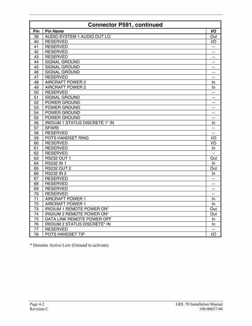
Page 4-2 GDL 59 Installation Manual Revision C 190-00837-00
Connector P591, continued Pin Pin Name I/O 39 AUDIO SYSTEM 1 AUDIO OUT LO Out 40 RESERVED I/O 41 RESERVED -- 42 RESERVED -- 43 RESERVED -- 44 SIGNAL GROUND -- 45 SIGNAL GROUND -- 46 SIGNAL GROUND -- 47 RESERVED -- 48 AIRCRAFT POWER 2 In 49 AIRCRAFT POWER 2 In 50 RESERVED -- 51 SIGNAL GROUND -- 52 POWER GROUND -- 53 POWER GROUND -- 54 POWER GROUND -- 55 POWER GROUND -- 56 IRIDIUM 1 STATUS DISCRETE 1* IN In 57 SPARE -- 58 RESERVED -- 59 POTS HANDSET RING I/O 60 RESERVED I/O 61 RESERVED In 62 RESERVED -- 63 RS232 OUT 1 Out 64 RS232 IN 1 In 65 RS232 OUT 2 Out 66 RS232 IN 2 In 67 RESERVED -- 68 RESERVED -- 69 RESERVED -- 70 RESERVED -- 71 AIRCRAFT POWER 1 In 72 AIRCRAFT POWER 1 In 73 IRIDIUM 1 REMOTE POWER ON* Out 74 IRIDIUM 2 REMOTE POWER ON* Out 75 DATA LINK REMOTE POWER OFF In 76 IRIDIUM 2 STATUS DISCRETE* IN In 77 RESERVED -- 78 POTS HANDSET TIP I/O
* Denotes Active Low (Ground to activate)

GDL 59 Installation Manual Page 4-3 190-00837-00 Revision C
4.2 Power Functions
4.2.1 Aircraft Power
The GDL 59 has four inputs pins for the two Aircraft Power busses of 14/28VDC. For 28V systems, only one pin from each Aircraft Power input (pin 71 or 72 for Aircraft Power 1, and pin 48 or 49 for Aircraft Power 2) is required, plus the same number of Power Ground pins. For 14V systems, both pins from each Aircraft Power (1 & 2) input are required, plus the same number of Power Ground pins. Pin Name Connector Pin I/O AIRCRAFT POWER 1 P591 71 In AIRCRAFT POWER 1 P591 72 In AIRCRAFT POWER 2 P591 48 In AIRCRAFT POWER 2 P591 49 In POWER GROUND P591 52 -- POWER GROUND P591 53 -- POWER GROUND P591 54 -- POWER GROUND P591 55 --
AIRCRAFT POWER 1 and AIRCRAFT POWER 2 are “diode ORed” to provide power redundancy.
4.2.2 Remote Power Off
The GDL 59 powers down upon receiving the remote power-off signal. DATA LINK REMOTE PWR OFF is a non-configurable discrete input conforming to:
a) Low: 0 VDC < Vin < 3.5 VDC, OR Rin > 100k ohms (inactive)
b) High: 8 VDC < Vin < 36 VDC (active)
Pin Name Connector Pin I/O DATA LINK REMOTE POWER OFF P591 75 In
4.3 Installation Selection Pins
4.3.1 Iridium Status Inputs
Pin Name Connector Pin I/O IRIDIUM 1 STATUS DISCRETE* IN P591 56 In IRIDIUM 2 STATUS DISCRETE* IN P591 76 In

Page 4-4 GDL 59 Installation Manual Revision C 190-00837-00
4.3.2 Remote Power On
These outputs are used to power on or off GSR 56 units used in the installation. DISCRETE OUT* pins: INACTIVE: Floating (can be pulled up to externally sourced Vout in the range 0 ≤ Vout ≤ 33VDC) Leakage current in the INACTIVE state is typically ≤ 10 uA to ground ACTIVE: Vout ≤ 0.5VDC with ≤ 20 mA sink current Sink current must be externally limited to 20 mA max Pin Name Connector Pin I/O IRIDIUM 1 REMOTE POWER ON* P591 73 Out IRIDIUM 2 REMOTE POWER ON* P591 74 Out
• Denotes Active Low (Ground to activate)
4.4 Serial Data
4.4.1 Avionics Ethernet HSDB
The GDL 59 has two Ethernet based high speed data busses (HSDB) that are used to interface with other LRUs in the Garmin Integrated Flight Deck system. These busses meet the hardware aspects of IEEE standard 802.3 for 10/100 Base T Ethernet communications. Pin Name Connector Pin I/O AVIONICS ETHERNET IN 1 A P591 10 In AVIONICS ETHERNET IN 1 B P591 30 In AVIONICS ETHERNET OUT 1 A P591 9 Out AVIONICS ETHERNET OUT 1 B P591 29 Out AVIONICS ETHERNET IN 2 A P591 4 In AVIONICS ETHERNET IN 2 B P591 24 In AVIONICS ETHERNET OUT 2 A P591 3 Out AVIONICS ETHERNET OUT 2 P591 23 Out

GDL 59 Installation Manual Page 4-5 190-00837-00 Revision C
4.4.2 User Ethernet
The GDL 59 has three Ethernet data busses that meet the hardware aspects of IEEE standard 802.3 for 10/100 Base T Ethernet communications.
NOTE
Garmin recommends leaving USER ETHERNET 3 unconnected, as it may be used for other functions in the future.
Pin Name Connector Pin I/O USER ETHERNET IN 3 A P591 6 In USER ETHERNET IN 3 B P591 26 In USER ETHERNET OUT 3 A P591 5 Out USER ETHERNET OUT 3 B P591 25 Out USER ETHERNET IN 4 A P591 8 In USER ETHERNET IN 4 B P591 28 In USER ETHERNET OUT 4 A P591 7 Out USER ETHERNET OUT 4 B P591 27 Out USER ETHERNET IN 5 A P591 2 In USER ETHERNET IN 5 B P591 22 In USER ETHERNET OUT 5 A P591 1 Out USER ETHERNET OUT 5 B P591 21 Out
4.4.3 RS-232 Serial Input/Output
The RS-232 outputs conform to EIA/TIA-232C with an output voltage swing of at least ±5 V when driving a standard RS-232 load. RS-232 Channels 1 and 2 are to be used for communication with optional GSR 56 units (if installed).
Pin Name Connector Pin I/O RS-232 OUT 1 P591 63 Out RS-232 IN 1 P591 64 In RS-232 OUT 2 P591 65 Out RS-232 IN 2 P591 66 In

Page 4-6 GDL 59 Installation Manual Revision C 190-00837-00
4.4.4 Handset POTS (Plain Old Telephone Service) Input/Output
The POTS interface shall: 1) Be capable of detecting a hook-switch flash signal where the on-hook time is 200ms. 2) Be capable of detecting an on-hook condition where on-hook is represented by a load of 10K Ω
or greater between the tip and ring leads. 3) Deliver an on-hook voltage between -42 and -56 VDC into a 1M Ω or greater load. 4) Be capable of delivering a power ring signal with a frequency between 15 Hz and 68 Hz and
amplitude between 40 and 120 Vrms into a 2.3K Ω +/- 10% load. 5) Maintain a source current of 25mA +/- 5% into an off-hook load.
Up to two analog POTS handsets may be connected to these lines. Pin Name Connector Pin I/O POTS HANDSET RING P591 59 I/O POTS HANDSET TIP P591 78 I/O
4.5 Audio Connections
4.5.1 Iridium Audio Channels
The Iridium Audio channels interface with the GSR 56 units. See Appendix B for sample interconnect drawing. Pin Name Connector Pin I/O IRIDIUM AUDIO IN 1 HI P591 15 In IRIDIUM AUDIO IN 1 LO P591 34 In IRIDIUM AUDIO OUT 1 HI P591 16 Out IRIDIUM AUDIO OUT 1 LO P591 35 Out IRIDIUM AUDIO IN 2 HI P591 13 In IRIDIUM AUDIO IN 2 LO P591 32 In IRIDIUM AUDIO OUT 2 HI P591 14 Out IRIDIUM AUDIO OUT 2 LO P591 33 Out
4.5.2 Audio System Channels
The Audio System channels connect to other LRUs, such as the GMA Audio Panel. Pin Name Connector Pin I/O AUDIO SYSTEM 1 AUDIO IN HI P591 19 In AUDIO SYSTEM 1 AUDIO IN LO P591 38 In AUDIO SYSTEM 1 AUDIO OUT HI P591 20 Out AUDIO SYSTEM 1 AUDIO OUT LO P591 39 Out AUDIO SYSTEM 2 AUDIO IN HI P591 17 In AUDIO SYSTEM 2 AUDIO IN LO P591 36 In AUDIO SYSTEM 2 AUDIO OUT HI P591 18 Out AUDIO SYSTEM 2 AUDIO OUT LO P591 37 Out
NOTE
For best noise immunity, it is recommended to connect AUDIO SYTEM 2 AUDIO OUT (pins 18 and 37) to a differential input only.

APPENDIX A OUTLINE AND INSTALLATION DRAWINGS
GDL 59 Installation Manual Page A-1 (Page A-2 Blank) 190-00837-00 Revision C
7.26 184.4
6.300 160.02
9.07 230.4
.480 12.19
3.0 76
4.3 109
NOTES:DIMENSIONS: INCHES[mm]1.DIMENSIONS ARE SHOWN FOR REFERENCE ONLY.2.MOUNTING HOLE FOR #6 FLAT HEAD3.100 CSK SCREW (12 PLCS)
6.900 175.26TYP
1.23 31.1
.480 12.19TYP
.36 9.1TYP
.6 15
4X NOTE 3
4X NOTE 3
ANTENNA
J591
.480 12.19TYP
.360 9.14TYP .377 9.58
TYP
3.727 94.67TYP
4X NOTE 3
MODULAR INSTALLATION
Figure A-1. GDL 59 Modular Rack Outline Drawing (Sheet 1 of 2)

APPENDIX A OUTLINE AND INSTALLATION DRAWINGS
GDL 59 Installation Manual Page A-3 (Page A-4 Blank) 190-00837-00 Revision C
PART OFNUTPLATE KIT011-00915-00
8 PLCS
GDL 59011-01746-00
MODULAR RACK115-00411-00
NUTPLATE KIT011-00915-00 (PREFERRED WITH GARMIN SYSTEM RACK)OR011-01148-00 (NOT SHOWN)
PART OFCONNECTOR KIT011-01760-002 PLCS
BACK PLATE KIT011-00796-02
CONNECTOR KIT011-01760-00
Figure A-1. GDL 59 Modular Rack Outline Drawing (Sheet 2)

APPENDIX A OUTLINE AND INSTALLATION DRAWINGS
GDL 59 Installation Manual Page A-5 (Page A-6 Blank) 190-00837-00 Revision C
2X 4.500 114.30
2X 1.125 28.58
7.910 200.91
.58 TYP14.75.125 TYP130.17
2X 6.914 175.62
3X 6.426 163.22
8.710 221.23
9.13 231.9
4X NOTE 3
2X 1.47 37.3
.7 19
ANTENNA
J591
2X 4.458 113.222X 1.60 40.5
2X .728 18.49
2X .37 9.4
4X NOTE 4
2X 4.500 114.30
2X 1.63 41.3
3.6 91
4.0 101
4X NOTE 3
STANDALONE INSTALLATION
NOTES:1. DIMENSIONS: INCHES[mm]2. DIMENSIONS ARE SHOWN FOR REFERENCE ONLY.3. MOUNTING HOLE FOR #6 FLAT HEAD 100 CSK SCREW (8 PLCS)4. MOUNTING HOLE FOR #8 PAN HEAD SCREW (4 PLCS)
Figure A-2. GDL 59 Stand-alone Rack Outline Drawing (Sheet 1 of 2)

APPENDIX A OUTLINE AND INSTALLATION DRAWINGS
GDL 59 Installation Manual Page A-7 (Page A-8 Blank) 190-00837-00 Revision C
GDL 59011-01746-00
STANDALONE RACK115-00658-00
PART OFCONNECTOR KIT011-01760-002 PLCS
STANDALONE INSTALLATION
BACK PLATE KIT011-00796-02
CONNECTOR KIT011-01760-00
Figure A-2. GDL 59 Stand-alone Rack Outline Drawing (Sheet 2)

APPENDIX B INTERCONNECT DRAWING
GDL 59 Installation Manual Page B-1 (Page B-2 Blank) 190-00837-00 Revision C
P691DATA LINK
GDL 69A
33
3130
32ETHERNET OUT 3 A
ETHERNET IN 3 AETHERNET IN 3 B
ETHERNET OUT 3 B
S
SEE NOTE 7
GDL 59 DATALINK
SEE NOTE 8
AVIONICS ETHERNET OUT 1 B
AVIONICS ETHERNET IN 1 B
29
30
9
AVIONICS ETHERNET IN 1 A 10
AVIONICS ETHERNET OUT 1 A
P591
71725253
AIRCRAFT POWER 1AIRCRAFT POWER 1
POWER GROUNDPOWER GROUND
HANDSET 1
RINGTIP
S
BLUWHT
59
78
TRANSCEIVERNO.1 GSR56
1P561
AUDIO IN LOAUDIO IN HI
54WHT
BLU
AUDIO OUT LOAUDIO OUT HI
BLUWHT
21
REMOTE POWER ON16
RS-232 OUT
RS-232 IN
12
13
IRIDIUM 1 REMOTE POWER ON* 73
IRIDIUM AUDIO 1 OUT HIIRIDIUM AUDIO 1 OUT LO
IRIDIUM AUDIO 1IN HIIRIDIUM AUDIO 1IN LO
1635
1534 BLU
WHT
BLU
S
WHT
S
RS 232 OUT 1SIGNAL GROUND
RS 232 IN 1
634464 ORN
BLUWHT
ORNBLUWHT
SIGNAL GROUND14
56 31 STATUS DISCRETE
WI-FI ANTENNA
POTS HANDSET TIPPOTS HANDSET RING
IRIDIUM 1 STATUS DISCRETE* IN
TEL AUDIO IN HITEL AUDIO IN LO
TEL MIC AUDIO OUT HITEL MIC AUDIO OUT LO
4342
6223
1P3471 GMA 1347 AUDIO PANEL
WHTBLU
BLUWHT
BLUWHT
BLUWHT
S
S
AUDIO SYSTEM 1 IN HIAUDIO SYSTEM 1 IN LO
AUDIO SYSTEM 1 OUT HIAUDIO SYSTEM 1 OUT LO
1938
2039
8
1A
P592
Figure B-1. GDL 59 Example Interconnect