data comm4&5data communications (under graduate course) lecture 3 of 5
TRANSCRIPT
Dr. Randa Elanwar
2012-2013
Physical sources naturally generate signals that contain a significant amount of information that is redundant of which their transmission is wasteful of communication resources.
For efficient transmission the redundant information should be removed from the signal prior to transmission with no loss of information. This is referred to as ‘data compaction’ or ‘lossless data compression’.
Data Communications Dr. Randa Elanwar 2012-2013 2
The entropy of the source sets the fundamental limit of redundancy removal.
Basically, data compaction is achieved by assigning short descriptions to the most frequent outcomes of the source output and longer descriptions to the less frequent ones.
Prefix codingA source coding scheme used for data compaction. It is not only decodable but also offers the possibility of having an average code word length close to the source entropy. I.e. Code efficiency approaches 100%
3Data Communications Dr. Randa Elanwar 2012-2013

A prefix code is defined as a code in which no code word is the prefix of any other code word.
Example
Code 1 is not a prefix code since the bit 0, the code word of S0, is a prefix of 00, the code word of S2. Likewise, the bit 1, the code word of S1, is a prefix of 11, the code word of S3. Similarly, we may show that code 3 is not a prefix code but code 2 is.
4Data Communications Dr. Randa Elanwar 2012-2013
Source Symbol Probability of occurrence Code 1 Code 2 Code 3
S0 0.5 0 0 0
S1 0.25 1 10 01
S2 0.125 00 110 011
S3 0.125 11 111 0111

Prefix code is distinguished from other uniquely decodable codes by the fact that the end of a code word is always recognizable.
Hence the decoding of a prefix can be accomplished as soon as the binary sequence representing a source symbol is fully received. For this reason, prefix codes are also referred to as instantaneous codes.
Data Communications Dr. Randa Elanwar 2012-2013 5

Huffman coding
It is an important class of prefix codes. The basic idea behind it is to assign to each symbol a sequence of bits roughly equal in length to the amount of information conveyed by this symbol.
The end result is a source code whose average code word length approaches the source entropy H(S).
Data Communications Dr. Randa Elanwar 2012-2013 6

Huffman coding
The idea of the Huffman code is to replace the symbol set of the memory less source by a simpler one.
This reduction is continued step-by-step until we are left with a final set with only 2 symbols for which (0, 1) is an optimal code.
Starting from this trivial code we work backward.
Data Communications Dr. Randa Elanwar 2012-2013 7
Specifically, the Huffman encoding algorithm proceeds as follows:
1. The source symbols are listed in order of descending probability of occurrence. The two source symbols of lowest probability are regarded as being combined into a new source symbol with probability equal to the sum of the two original probabilities. (The list of symbols is now reduced by 1)
2. Update the symbol list by placing the probability of the new symbol according to its value.
Data Communications Dr. Randa Elanwar 2012-2013 8
3. The procedure is repeated until we are left with a final list of source symbols of only two for which a 0 and a 1 are assigned.
4. The code for each original source symbol is found by working back ward and tracing the sequence of 0’s and 1’s assigned to that symbol as well as its successors.
Data Communications Dr. Randa Elanwar 2012-2013 9
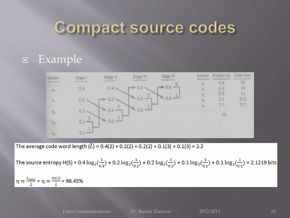
Example
Data Communications Dr. Randa Elanwar 2012-2013 10
Redundancy plays an important role in communications. It is essential for reliable communication.
Because of redundancy we are able to decode a message accurately despite errors in the received message. Redundancy thus combats noise.
If all the redundancy in a message is removed it would take much less time in transmission but if an error occurs at the receiver it would be difficult to make sense of the received message.
Data Communications Dr. Randa Elanwar 2012-2013 11
For example, in order to transmit 16 symbols we may use a group of 4 binary pulses (‘0000’, ‘0001’, ‘0010’, … ‘1111’).
In this coding scheme no redundancy exists. If an error occurs in the reception of even one of the pulses, the receiver will produce a wrong value. Here we may use redundancy to eliminate the effect of possible errors caused by channel noise.
Thus if we add to each code word one more pulse as to make the number of positive pulses even we have a code that can detect a single error in any place.
Data Communications Dr. Randa Elanwar 2012-2013 12
Thus, to the code word 0001 we add a fifth pulse to make a new code word 00011. Now the number of positive pulses is 2 (even).
If a single error occurs in any position, this parity will be violated. The receiver then will request retransmission of the message.
This code can only detect single error but cannot locate (correct) it. It also cannot detect even number of errors. By introducing more redundancy it is possible not only to detect but also to correct errors.
We will know more about redundancy later when we study Error correcting coding
Data Communications Dr. Randa Elanwar 2012-2013 13

After over viewing different coding techniques it’s time now to understand how can we reach our target of ‘Efficient transmission’.
In other words, we finally have represented our information after compression and coding to a sequence of ‘1’ and ‘0’, we need to know what is the best way of transmitting this sequence such that we save our resources (power, bandwidth) and achieve correct signal recovery at the receiver.
Data Communications Dr. Randa Elanwar 2012-2013 14
We can measure the “GOODNESS” of a communication system in many ways:
How close is the estimated signal to the original signal
Better estimate = higher quality transmission
Bit Error Rate (BER) for digital signal
How much power is required to transmit a signal?
Lower power = longer battery life, less interference
How much bandwidth B is required to transmit a signal?
Less B means more users can share the channel
How much information is transmitted?
In digital systems information is expressed in bits/sec.
Data Communications Dr. Randa Elanwar 2012-2013 15
Time domain vs. frequency domain Every signal can be represented in two different ways:
time domain representation and frequency domain representation.
A time-domain graph shows how a signal changes over time, whereas a frequency-domain graph shows how much of the signal lies within each given frequency band over a range of frequencies.
Why do we need to have a frequency domain representation of a signal? Because Frequency analysis simplifies the understanding and interpretation of the effects of various time-domain operations.
Data Communications Dr. Randa Elanwar 2012-2013 16

A given function or signal can be converted between the time and frequency domains with a pair of mathematical operators called a transform.
An example is the Fourier transform, which decomposes a function into the sum of a number of sine waves at different frequencies.
The frequency domain representation of the signal (called ‘spectrum’) is the graph showing the Fourier coefficients values versus the corresponding frequency components.
Data Communications Dr. Randa Elanwar 2012-2013 17

The frequency spectrum of a time-domain signal is a representation of that signal in the frequency domain.
The frequency spectrum can be generated via a Fourier transform of the signal, and the resulting values are usually presented as amplitude and phase, both plotted versus frequency.
Thus, Any signal that can be represented as an amplitude that varies with time has a corresponding frequency spectrum.
Data Communications Dr. Randa Elanwar 2012-2013 18

The formulation for Fourier series re-writes sines and cosines as complex exponentials.
These complex exponentials sometimes contain negative frequencies. They practically do not exist but having even symmetry simplifies computations a lot.
Data Communications Dr. Randa Elanwar 2012-2013 19
Power spectral density The power spectral density (PSD) describes how the
power of a signal is distributed with frequency. It represents the power per unit bandwidth of the spectral components at different frequencies.
For technical reasons, it is desirable to have zero PSD at frequency 0 hertz.
Note that: It has been proven that if a signal is narrow in time domain (has short period) it will be wide in frequency domain and vice versa since frequency is the reciprocal of time period.
F = 1 / T0
Data Communications Dr. Randa Elanwar 2012-2013 20

DC component When describing a periodic function in the frequency
domain, the DC bias, DC component, DC offset, or DC coefficient is the mean value of the waveform. If the mean amplitude is zero, there is no DC offset.
A waveform without a DC component is known as a DC-balanced waveform. DC-balanced waveforms are useful in communications systems to avoid voltage imbalance problems between connected systems or components.
DC offset is usually undesirable when it causes saturation or change in the operating point of an amplifier. In signal processing terms, DC offset can be reduced in real-time by a high-pass filter.
Data Communications Dr. Randa Elanwar 2012-2013 21
Binary data can be transmitted using a number of different types of pulses. The choice of a particular pair of pulses to represent the symbols 1 and 0 is called Line Coding and the choice is generally made on the grounds of one or more of the following considerations:
Presence or absence of a DC level.
Power Spectral Density- particularly its value at 0 Hz.
Bandwidth.
Data Communications Dr. Randa Elanwar 2012-2013 22
BER performance (i.e. Probability of error).
Transparency (i.e. the property that any arbitrary symbol, or bit, pattern can be transmitted and received).
Ease of clock signal recovery for symbol synchronization.
Presence or absence of inherent error detection properties.
After line coding pulses may be filtered or otherwise shaped to further improve their properties: for example, their spectral efficiency and/ or immunity to intersymbol interference.
Data Communications Dr. Randa Elanwar 2012-2013 23
Signal Bandwidth
The transmission of Rb bits per second requires a theoretical minimum pulse bandwidth of Rb/2 Hz.
It was proven by Nyquist that in order to avoid overlapping in pulses transmission then the transmission rate on the channel has to be greater than twice the signal bandwidth (maximum frequency)
B = 1/T0 and Rb >2B then B<Rb/2
Data Communications Dr. Randa Elanwar 2012-2013 24
Transparency
Regenerative repeaters are used at regularly spaced intervals along a digital transmission line to detect the incoming digital signal and regenerate new clean pulses for further transmission along the line.
This process periodically eliminates the accumulation of noise and signal distortion along the transmission path.
Timing information (clock signal) between successive repeaters has to be extracted from the received signal.
Data Communications Dr. Randa Elanwar 2012-2013 25

The timing signal is sensitive to the incoming bit pattern, hence, if there are too many 0’s (no pulses) in a sequence this causes error in the timing information.
Thus; for reliable clock recovery at the receiver, one usually imposes a maximum run length constraint on the generated channel sequence, i.e., the maximum number of consecutive ones or zeros is bounded to a reasonable number.
The line code in which the bit pattern doesn’t affect the accuracy of the timing information is said to be transparent.
Data Communications Dr. Randa Elanwar 2012-2013 26
In other words, it should be possible to transmit a digital signal correctly regardless of the pattern of 1’s and 0’s and if the data is coded such that for every possible sequence of data, the coded signal is received faithfully, the code is transparent.
Data Communications Dr. Randa Elanwar 2012-2013 27

Error detection In information theory and coding theory with
applications in computer science and telecommunication, error detection and correction or error control are techniques that enable reliable delivery of digital data over unreliable communication channels.
Many communication channels are subject to channel noise, and thus errors may be introduced during transmission from the source to a receiver.
Error detection techniques allow detecting such errors, while error correction enables reconstruction of the original data.
Data Communications Dr. Randa Elanwar 2012-2013 28
1. Unipolar Signaling:
Unipolar signaling (also called on-off keying, OOK) is the type of line coding in which one binary symbol (representing a 0 for example) is represented by the absence of a pulse (i.e. a SPACE) and the other binary symbol (denoting a 1) is represented by the presence of a pulse (i.e. a MARK).
There are two common variations of unipolarSignaling: Non-Return to Zero (NRZ) and Return to Zero (RZ).
Data Communications Dr. Randa Elanwar 2012-2013 29
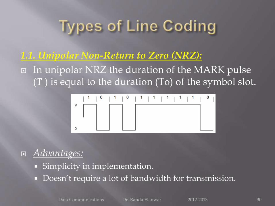
1.1. Unipolar Non-Return to Zero (NRZ):
In unipolar NRZ the duration of the MARK pulse (Ƭ ) is equal to the duration (To) of the symbol slot.
Advantages:
Simplicity in implementation.
Doesn’t require a lot of bandwidth for transmission.
Data Communications Dr. Randa Elanwar 2012-2013 30

Disadvantages: Presence of DC level (indicated by spectral line at 0 Hz). Does not have any error correction capability. Does not posses any clocking component for ease of
synchronization. Is not Transparent. Long string of zeros causes loss of
synchronization.
PSD of of Unipolar NRZ
Data Communications Dr. Randa Elanwar 2012-2013 31
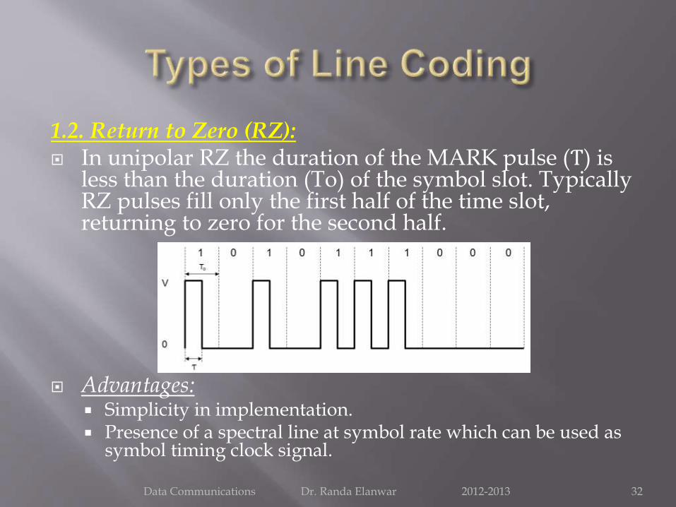
1.2. Return to Zero (RZ): In unipolar RZ the duration of the MARK pulse (Ƭ) is
less than the duration (To) of the symbol slot. Typically RZ pulses fill only the first half of the time slot, returning to zero for the second half.
Advantages: Simplicity in implementation. Presence of a spectral line at symbol rate which can be used as
symbol timing clock signal.
Data Communications Dr. Randa Elanwar 2012-2013 32
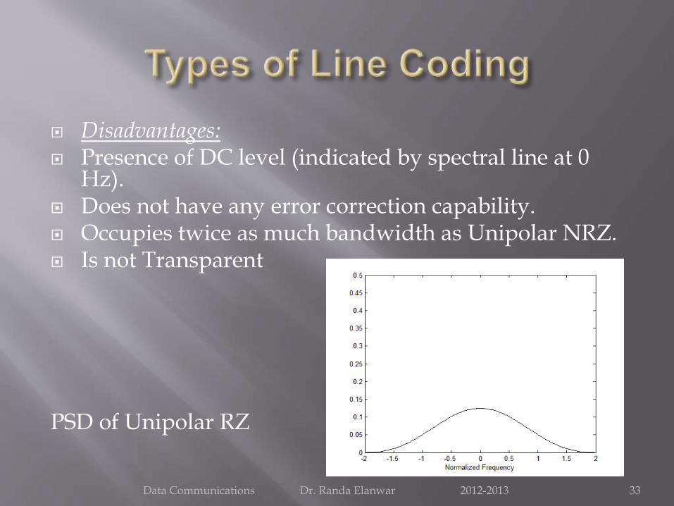
Disadvantages: Presence of DC level (indicated by spectral line at 0
Hz). Does not have any error correction capability. Occupies twice as much bandwidth as Unipolar NRZ. Is not Transparent
PSD of Unipolar RZ
Data Communications Dr. Randa Elanwar 2012-2013 33
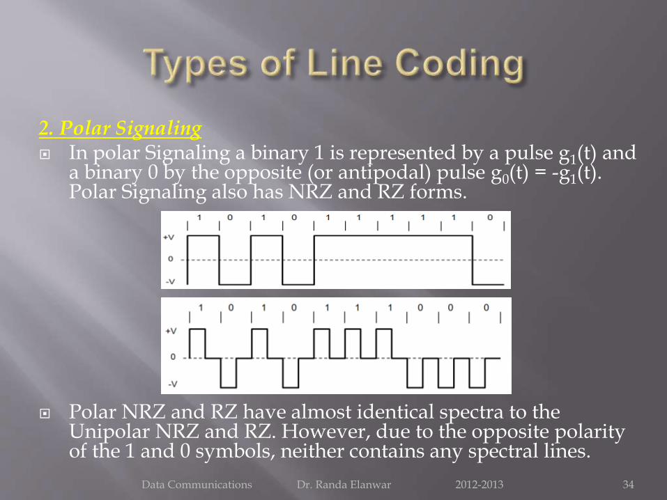
2. Polar Signaling In polar Signaling a binary 1 is represented by a pulse g1(t) and
a binary 0 by the opposite (or antipodal) pulse g0(t) = -g1(t). Polar Signaling also has NRZ and RZ forms.
Polar NRZ and RZ have almost identical spectra to the Unipolar NRZ and RZ. However, due to the opposite polarity of the 1 and 0 symbols, neither contains any spectral lines.
Data Communications Dr. Randa Elanwar 2012-2013 34

PSD of Polar NRZ PSD of Polar RZ
Data Communications Dr. Randa Elanwar 2012-2013 35

2.1. Polar Non-Return to Zero (NRZ):
Advantages:
Simplicity in implementation.
No DC component.
Disadvantages:
Does not have any error correction capability.
Does not posses any clocking component for ease of synchronization.
Is not transparent.
Data Communications Dr. Randa Elanwar 2012-2013 36

2.2. Polar Return to Zero (RZ):
Advantages: Simplicity in implementation.
No DC component.
Disadvantages: Does not have any error correction capability.
Does not posses any clocking component for easy synchronization. However, clock can be extracted by rectifying the received signal.
Occupies twice as much bandwidth as Polar NRZ.
Data Communications Dr. Randa Elanwar 2012-2013 37
3. BiPolar Signaling Bipolar Signaling is also called “alternate mark
inversion” (AMI) uses three voltage levels (+V, 0, -V) to represent two binary symbols.
Zeros, as in unipolar, are represented by the absence of a pulse and ones (or marks) are represented by alternating voltage levels of +V and –V.
Alternating the mark level voltage ensures that the bipolar spectrum has a null at DC.
Data Communications Dr. Randa Elanwar 2012-2013 38
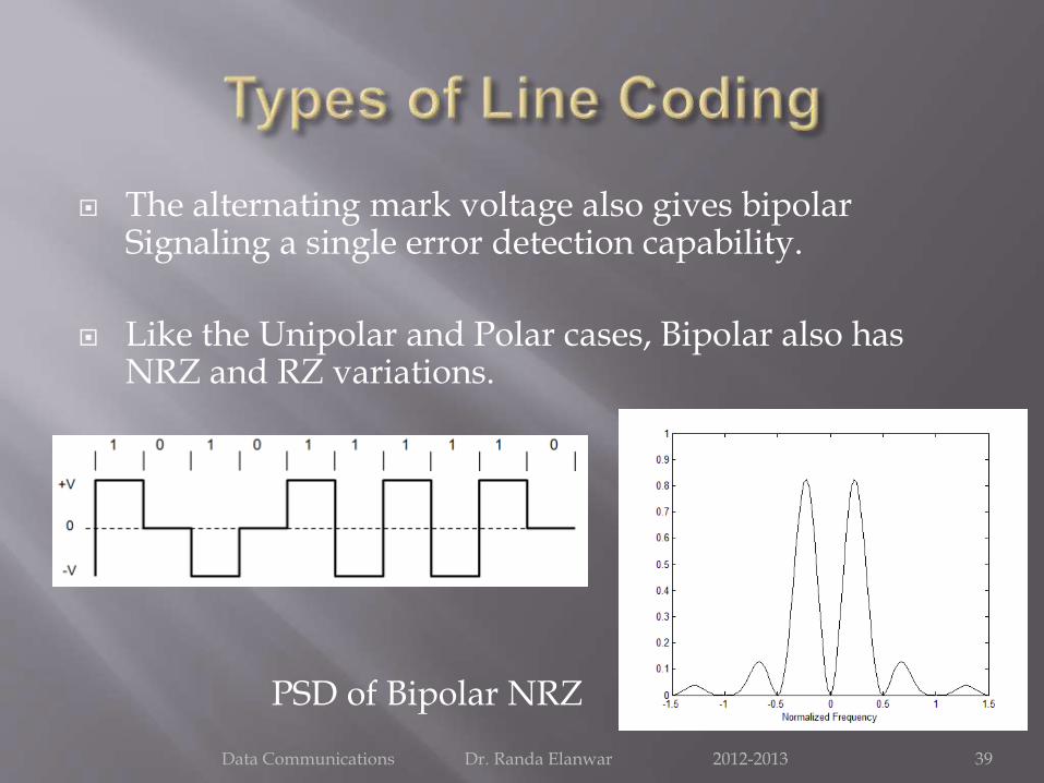
The alternating mark voltage also gives bipolar Signaling a single error detection capability.
Like the Unipolar and Polar cases, Bipolar also has NRZ and RZ variations.
PSD of Bipolar NRZ
Data Communications Dr. Randa Elanwar 2012-2013 39

3.1 BiPolar / AMI NRZ:
Advantages: No DC component.
Occupies less bandwidth than unipolar and polar NRZ schemes.
Possesses single error detection capability.
Disadvantages: Does not posses any clocking component for ease of
synchronization.
Is not Transparent.
Data Communications Dr. Randa Elanwar 2012-2013 40
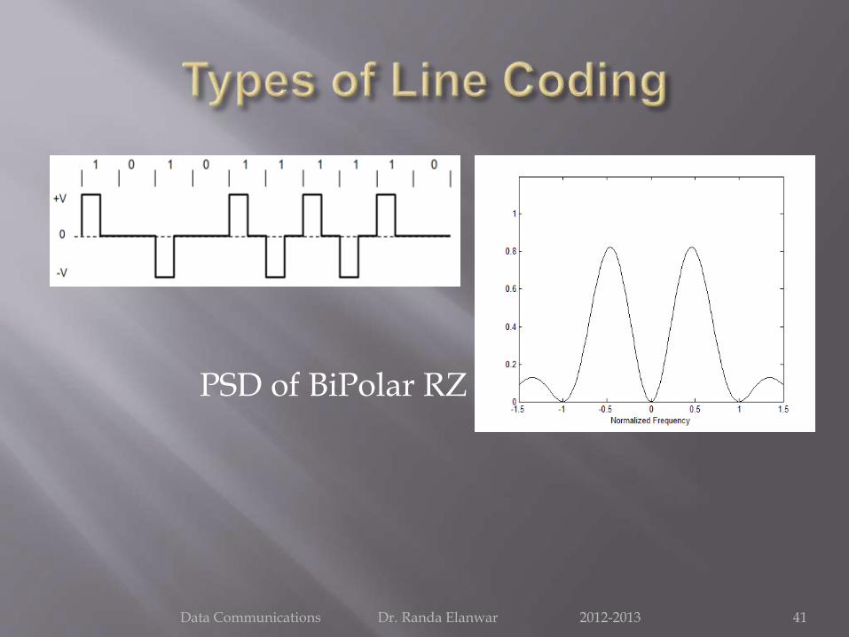
PSD of BiPolar RZ
Data Communications Dr. Randa Elanwar 2012-2013 41

3.2. BiPolar / AMI RZ:
Advantages: No DC component.
Occupies less bandwidth than unipolar and polar RZ schemes.
Possesses single error detection capability.
Clock can be extracted by rectifying (a copy of) the received signal.
Disadvantages: Is not Transparent.
Data Communications Dr. Randa Elanwar 2012-2013 42

4. Manchester Signaling In Manchester encoding , the duration of the bit is
divided into two halves. The voltage remains at one level during the first half and moves to the other level during the second half.
A ‘One’ is +ve in 1st half and -ve in 2nd half.A ‘Zero’ is -ve in 1st half and +ve in 2nd half.
Data Communications Dr. Randa Elanwar 2012-2013 43
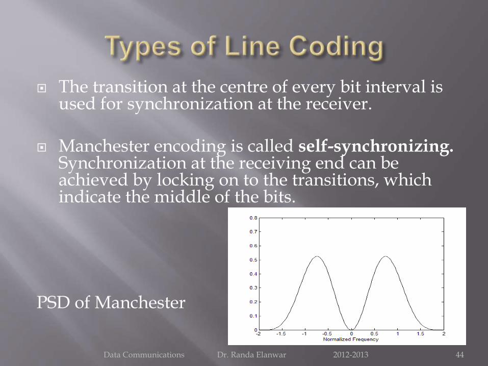
The transition at the centre of every bit interval is used for synchronization at the receiver.
Manchester encoding is called self-synchronizing. Synchronization at the receiving end can be achieved by locking on to the transitions, which indicate the middle of the bits.
PSD of Manchester
Data Communications Dr. Randa Elanwar 2012-2013 44
Advantages: No DC component. Easy to synchronise with. Is Transparent.
Disadvantages: Because of the greater number of transitions it occupies a
significantly large bandwidth. Does not have error detection capability.
These characteristic make this scheme unsuitable for use in Wide Area Networks. However, it is widely used in Local Area Networks such as Ethernet and Token Ring.
Data Communications Dr. Randa Elanwar 2012-2013 45
The received digital signal needs to be sampled at precise instants. This requires a clock signal at the receiver in synchronism with the clock signal at the transmitter.
In any communication system it is necessary that the timing operations at the receiver follow closely the corresponding operations at the transmitter.
For example, when the transmission path is interrupted, it is highly unlikely that transmitter and receiver clocks will continue to indicate the same time for long. Accordingly, we must set up a procedure for adding and detecting a synchronization pulse.
Data Communications Dr. Randa Elanwar 2012-2013 46

Three general methods of synchronization exist:1. The transmitter and receiver both follow the same master
timing source
2. Transmitting a separate synchronizing signal (pilot clock)
3. Self-synchronization, where timing information is extracted from the received signal itself.
The first method is suitable for large volumes of data and high speed communication systems because of its high cost.
Data Communications Dr. Randa Elanwar 2012-2013 47

In the second method a code element or a pulse is set aside at the end of a frame and to transmit this pulse every other frame only.
In this case the receiver searches the code words (one-by-one) for the pattern of 1s and 0s alternating at half the frame rate and establishes synchronization between the transmitter and receiver.
This is suitable when the available channel capacity is large compared to the data rate.
Data Communications Dr. Randa Elanwar 2012-2013 48
The third method is when the available channel capacity is small compared to the data rate thus is more efficient but implies short run lengths of 1s and 0s to avoid loss of synchronization. Hence sometimes scramblers are needed.
In general, a scrambler tends to make the data more random by removing long strings of 1s and 0s. It can be helpful in timing extraction by removing long strings of 0s in binary data.
They are primarily used for preventing unauthorized access. On the other hand, a matched descrambler is used at the intended receiver to undo the operations done by the scrambler at the transmitter and recover the original order of data sequence.
Data Communications Dr. Randa Elanwar 2012-2013 49