data centre security - cisco
TRANSCRIPT

© 2011 Cisco and/or its affiliates. All rights reserved. Cisco Connect 1 1 © 2013 Cisco and/or its affiliates. All rights reserved.
Toronto, Canada
May 30, 2013
Data Centre Security Best Practices and Achitecture
Mason Harris, CCIE #5916
Solutions Architect
Advanced Technology Team
Agenda
• Today’s DC Architecture
• Threat Prevention
• Threat Visibility
• Virtualized Security
• Validated Architectures
• Summary

© 2013 Cisco and/or its affiliates. All rights reserved. Cisco Connect 3
DC Architecure: Building Blocks
© 2012 Cisco and/or its affiliates. All rights reserved. Cisco Connect 4 © 2013 Cisco and/or its affiliates. All rights reserved. Cisco Connect 2013 4 Data Center Security
Building an Efficient DC Fabric to Scale
4
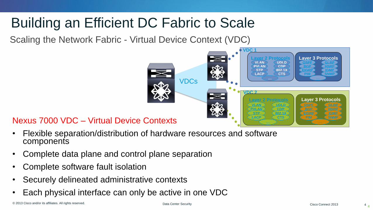
• Scaling the Network Fabric - Virtual Device Context (VDC)
Nexus 7000 VDC – Virtual Device Contexts
• Flexible separation/distribution of hardware resources and software components
• Complete data plane and control plane separation
• Complete software fault isolation
• Securely delineated administrative contexts
• Each physical interface can only be active in one VDC
Layer 2 Protocols Layer 3 Protocols VLAN
PVLAN OSPF BGP
EIGRP
GLBP HSRP IGMP
UDLD CDP
802.1X STP LACP PIM CTS SNMP
… …
VDC 1
Layer 3 Protocols OSPF
BGP
EIGRP
GLBP
HSRP
IGMP
PIM SNMP
…
VDC 2
Layer 2 Protocols VLAN
PVLAN
UDLD
CDP
802.1X STP
LACP CTS
…
VDCs
© 2012 Cisco and/or its affiliates. All rights reserved. Cisco Connect 5 © 2013 Cisco and/or its affiliates. All rights reserved. Cisco Connect 2013 5 Data Center Security
vPC Peers
vPC Peers
MCEC
5
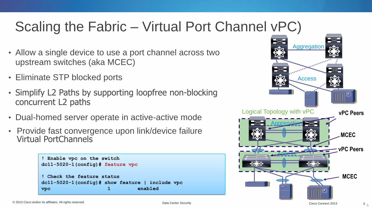
• Allow a single device to use a port channel across two upstream switches (aka MCEC)
• Eliminate STP blocked ports
• Simplify L2 Paths by supporting loopfree non-blocking concurrent L2 paths
• Dual-homed server operate in active-active mode
• Provide fast convergence upon link/device failure Virtual PortChannels
• Scaling the Fabric – Virtual Port Channel vPC)
Logical Topology with vPC
Aggregation
Access
Aggregation
Access
MCEC
! Enable vpc on the switch
dc11-5020-1(config)# feature vpc
! Check the feature status
dc11-5020-1(config)# show feature | include vpc
vpc 1 enabled

The Security Practicioner’s Challange
• How to integrate security in a dynamic network (the DC)
• Loss of traditional L2 and L3 boundaries
• Other technologies like VXLAN, OTV and Vmotion extend the network topology
• How do stateful inspection devices handle assymetric flows?
• Where can I get flow visibility if there isn’t a network “edge”?
• DC is rapidly changing, security services difficult to keep up

© 2013 Cisco and/or its affiliates. All rights reserved. Cisco Connect 7
Threat Prevention: Firewall and IPS

© 2012 Cisco and/or its affiliates. All rights reserved. Cisco Connect 8 © 2013 Cisco and/or its affiliates. All rights reserved. Cisco Connect 2013 8 Data Center Security
Why Deploy a Firewall in the DC?
• Firewalls provide a stateful inspection point for access control
• Can be either a physical appliance or virtual appliance
• Frequently positioned between VRFs or VDC for granular control and visibility
• Throughput is one consideration, but connection count is just as important due to applications and their services
• Provide user and application visibility as well as flow based services
• Virtual firewalls are an option where physical appliances can’t exist or rapid expansion of virtual services
8
© 2012 Cisco and/or its affiliates. All rights reserved. Cisco Connect 9 © 2013 Cisco and/or its affiliates. All rights reserved. Cisco Connect 2013 9 Data Center Security
Physical Firewalls: Service Modules and Appliances
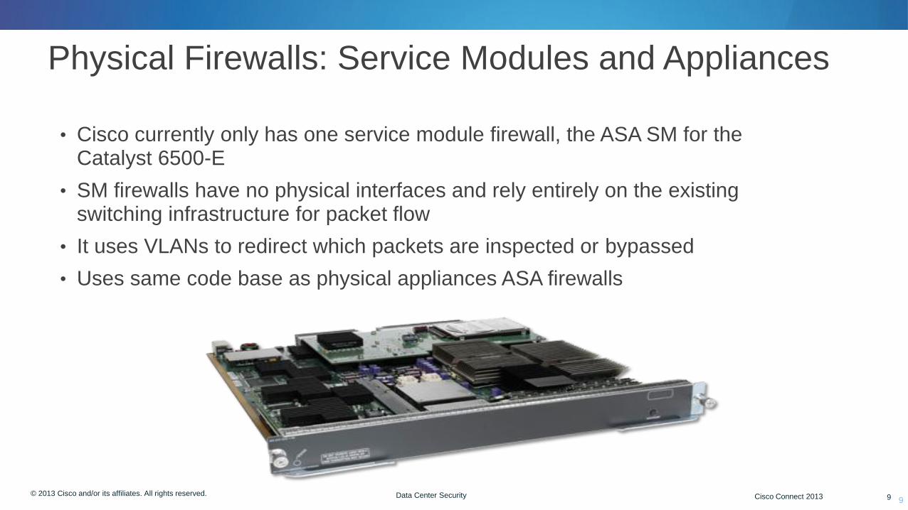
• Cisco currently only has one service module firewall, the ASA SM for the Catalyst 6500-E
• SM firewalls have no physical interfaces and rely entirely on the existing switching infrastructure for packet flow
• It uses VLANs to redirect which packets are inspected or bypassed
• Uses same code base as physical appliances ASA firewalls
9
© 2012 Cisco and/or its affiliates. All rights reserved. Cisco Connect 10 © 2013 Cisco and/or its affiliates. All rights reserved. Cisco Connect 2013 10 Data Center Security
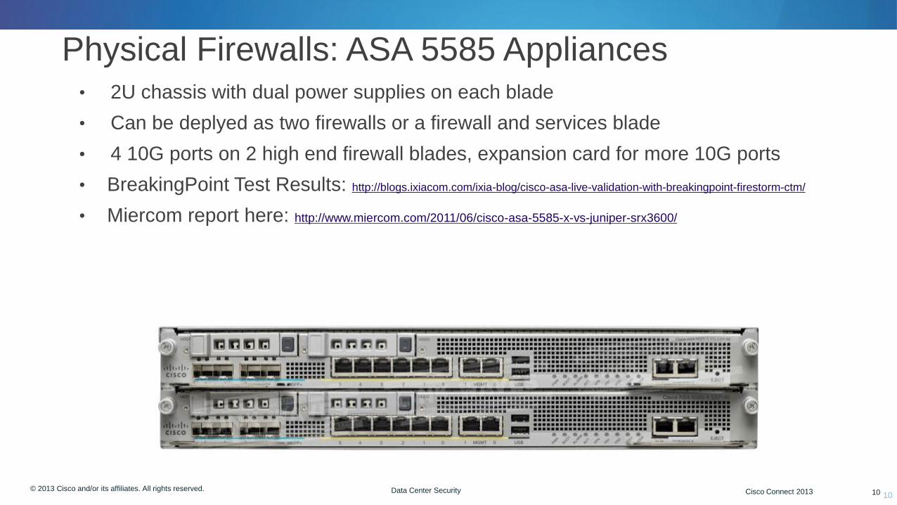
Physical Firewalls: ASA 5585 Appliances
10
• 2U chassis with dual power supplies on each blade
• Can be deplyed as two firewalls or a firewall and services blade
• 4 10G ports on 2 high end firewall blades, expansion card for more 10G ports
• BreakingPoint Test Results: http://blogs.ixiacom.com/ixia-blog/cisco-asa-live-validation-with-breakingpoint-firestorm-ctm/
• Miercom report here: http://www.miercom.com/2011/06/cisco-asa-5585-x-vs-juniper-srx3600/
© 2012 Cisco and/or its affiliates. All rights reserved. Cisco Connect 11 © 2013 Cisco and/or its affiliates. All rights reserved. Cisco Connect 2013 11 Data Center Security
Virtualized Firewalls and Virtual Firewalls
• Two types: multi-context mode and virtual firewalls
• Multi-context mode was originally designed for SMT (Secure Multi Tenant) deployments and is a licensed feature
• Virtual firewalls are software-only firewalls running in a hypervisor
• Cisco has two virtual firewalls: the Virtual Security Gateway (VSG) and the ASA1000V
• Both require the Nexus 1000V distributed virtual switch and an “Advanced” license
• Virtual firewalls can be deployed rapidly with typical orchestration tools, etc. but there is an added layer of operational complexity
• Virtual firewalls are heavily dependent on available RAM and CPU on the host server
• We’ll cover virtual firewalls shortly
11

© 2012 Cisco and/or its affiliates. All rights reserved. Cisco Connect 12 © 2013 Cisco and/or its affiliates. All rights reserved. Cisco Connect 2013 12 Data Center Security
4 Virtualized Firewalls - Common Configuration
12
• Firewalls can be in tranparent or routed mode or both (mixed mode 9.0+)
• Physical links are typically trunks but could be physical interfaces
• Contexts in routed mode can share VLANs, but not in transparent mode
VLAN 10 VLAN 20 VLAN 30 VLAN 40
VLAN 11 VLAN 21 VLAN 31 VLAN 41
VFW
1
VFW
2 VFW
3 VFW
4
© 2012 Cisco and/or its affiliates. All rights reserved. Cisco Connect 13 © 2013 Cisco and/or its affiliates. All rights reserved. Cisco Connect 2013 13 Data Center Security
What is a Transparent mode Firewall?
13
• Transparent Firewall (L2) mode provides an option in traditional L3 environments where existing services can’t be sent through the firewall
• Very popular architecture in data center environments
• In L2 mode:
• Routing protocols can establish adjacencies through the firewall
• Protocols such as HSRP, VRRP, GLBP can pass
• Multicast streams can traverse the firewall
• Non-IP traffic can be allowed (IPX, MPLS, BPDUs)
• Allows for three forwarding interfaces, inside and outside and DMZ
• NO dynamic routing protocol support or VPN support (sourced from ASA)
• Specific design requirements, reference Configuration Guide for details
© 2012 Cisco and/or its affiliates. All rights reserved. Cisco Connect 14 © 2013 Cisco and/or its affiliates. All rights reserved. Cisco Connect 2013 14 Data Center Security
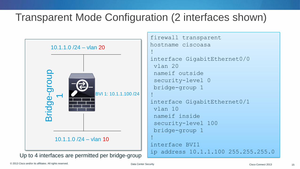
How Does Transparent Mode Work?
• Firewall functions like a bridge (“bump in the wire”) at L2, only ARP packets pass without an explicit ACL
• Still can use traditional ACLs on the firewall
• Does not forward Cisco Discovery Protocol (CDP)
• Same subnet exists on all interfaces in the bridge-group
• Different VLANs on inside and outside interfaces
• In addition to Extended ACLs, use an EtherType ACL to restrict or allow L2 protocols
© 2012 Cisco and/or its affiliates. All rights reserved. Cisco Connect 15 © 2013 Cisco and/or its affiliates. All rights reserved. Cisco Connect 2013 15 Data Center Security
10.1.1.0 /24 – vlan 10
10.1.1.0 /24 – vlan 20
BVI 1: 10.1.1.100 /24
firewall transparent
hostname ciscoasa
!
interface GigabitEthernet0/0
vlan 20
nameif outside
security-level 0
bridge-group 1
!
interface GigabitEthernet0/1
vlan 10
nameif inside
security-level 100
bridge-group 1
!
interface BVI1
ip address 10.1.1.100 255.255.255.0
Transparent Mode Configuration (2 interfaces shown)
Brid
ge
-gro
up
1
Up to 4 interfaces are permitted per bridge-group
© 2012 Cisco and/or its affiliates. All rights reserved. Cisco Connect 16 © 2013 Cisco and/or its affiliates. All rights reserved. Cisco Connect 2013 16 Data Center Security
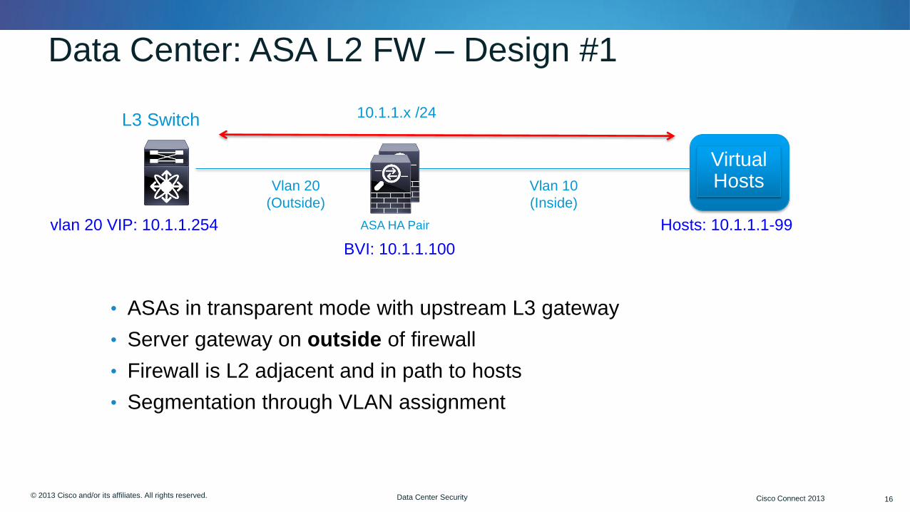
Data Center: ASA L2 FW – Design #1
• ASAs in transparent mode with upstream L3 gateway
• Server gateway on outside of firewall
• Firewall is L2 adjacent and in path to hosts
• Segmentation through VLAN assignment
Vlan 10
(Inside)
vlan 20 VIP: 10.1.1.254
L3 Switch
Hosts: 10.1.1.1-99
10.1.1.x /24
Vlan 20
(Outside)
ASA HA Pair
BVI: 10.1.1.100
Virtual Hosts

© 2012 Cisco and/or its affiliates. All rights reserved. Cisco Connect 17 © 2013 Cisco and/or its affiliates. All rights reserved. Cisco Connect 2013 17 Data Center Security
Data Center: ASA L2 FW – Design #2
VDC-Out
Outside Inside
VDC-In
HSRP VIP: 10.1.1.254
Single L2 Domain
Firewalls for Intra-VDC Traffic
• ASA in either L2 or L3 mode, L2 is optimal in most cases
• Add VRFs on Cat 6500 or Nexus 7K for segmentation
• Server gateway inside of firewall
• Minimizes firewall failures, route around failures if needed
Virtual Hosts vlan 20 vlan x vlan y
10.199.199.2 10.199.199.1

© 2012 Cisco and/or its affiliates. All rights reserved. Cisco Connect 18 © 2013 Cisco and/or its affiliates. All rights reserved. Cisco Connect 2013 18 Data Center Security
N7k1-VDC-2 Aggregation
vrf1 vrf2
ASA L2 FW – Design #3
• Transparent (L2) firewall services are “sandwiched” between Nexus VDCs
• Allows for other services (IPS, LB, etc) to be layered in as needed
• ASAs can be virtualized to for 1x1 mapping to VRFs
• Useful for topologies that require a FW between aggregation and core
• Downside is that most/all traffic destined for Core traverses FW; possible bottleneck, etc.
• Firewalls could be L2 or L3
N7k1-VDC-1 Core
vrf1 vrf2
Firewalls for Inter-VDC Traffic

© 2012 Cisco and/or its affiliates. All rights reserved. Cisco Connect 19 © 2013 Cisco and/or its affiliates. All rights reserved. Cisco Connect 2013 19 Data Center Security
Interface Redundancy: Port Channels
19
• Port channel support was added to the ASA in 8.4 (2011)
• Best practice: Utilize Link Aggregation Control Protocol (LACP) where possible
• LACP dynamically adds and removes (if necessary) links to the port channel bundle
• Up to 8 active links and 8 standby links are supported in the channel
• Link aggregation benefit
• Best practice in the DC is to use Virtual Port Channels
interface TenGigabitEthernet0/8
channel-group 40 mode active
no nameif
no security-level
!
interface TenGigabitEthernet0/9
channel-group 40 mode active
no nameif
no security-level
!
interface Port-channel40
nameif inside
ip add 10.1.1.2 255.255.255.0
Actively negotiate LACP with switch

© 2012 Cisco and/or its affiliates. All rights reserved. Cisco Connect 20 © 2013 Cisco and/or its affiliates. All rights reserved. Cisco Connect 2013 20 Data Center Security
‘Show port-channel summary' on ASA
Flags: D – down P - bundled in port-channel
I - stand-alone s – suspended
H - Hot-standby (LACP only)
U - in use N - not in use, no aggregation/nameif
M - not in use, no aggregation due to minimum links not met
w - waiting to be aggregated
Number of channel-groups in use: 1
Group Port-channel Protocol Span-cluster Ports
------+-------------+---------+------------+---------------------------
40 Po40(U) LACP No Te0/8(P) Te0/9(P)
20

© 2012 Cisco and/or its affiliates. All rights reserved. Cisco Connect 21 © 2013 Cisco and/or its affiliates. All rights reserved. Cisco Connect 2013 21 Data Center Security
Virtual Port Channels (VPC) and the ASA
21
• Virtual Port Channels (VPC) are port channels where both links are actively forwarding traffic
• Only two uplinks
• VPC was created to solve two inherent network problems: Spanning-tree recalculation times and unused capacity in redundant L2 uplinks (due to STP blocks)
• No additional config required on ASA
• Supported in Nexus devices
• VPC Design Guide: http://www.cisco.com/en/US/prod/collateral/switches/ps9441/ps9670/C07-572830-00_Agg_Dsgn_Config_DG.pdf Nexus 5K/7Ks
ASA

© 2013 Cisco and/or its affiliates. All rights reserved. Cisco Connect 22
Firewall Clustering

© 2012 Cisco and/or its affiliates. All rights reserved. Cisco Connect 23 © 2013 Cisco and/or its affiliates. All rights reserved. Cisco Connect 2013 23 Data Center Security
ASA Clustering Design Guidelines
• Up to 8 ASAs are supported in a cluster (minimum of two) and all must be the same model and DRAM (only flash memory can differ)
• All cluster units must share same software except during upgrade (e.g. 9.0(0)1 to 9.0(0)3)
• Approximate maximum cluster throughput is ~ 70% of combined throughput and connections of units in the cluster
• Cluster elects one master that syncs configuration with other members
• Supported in both routed (L3) and transparent (L2) firewall modes
• Requires at least one cluster control interface on ASA for cluster control plane – this is analogous to state and failover link in A/S today
• Cluster control links must be sized properly to accept a load that is equal to or greater than the cluster throughput
23
© 2012 Cisco and/or its affiliates. All rights reserved. Cisco Connect 24 © 2013 Cisco and/or its affiliates. All rights reserved. Cisco Connect 2013 24 Data Center Security
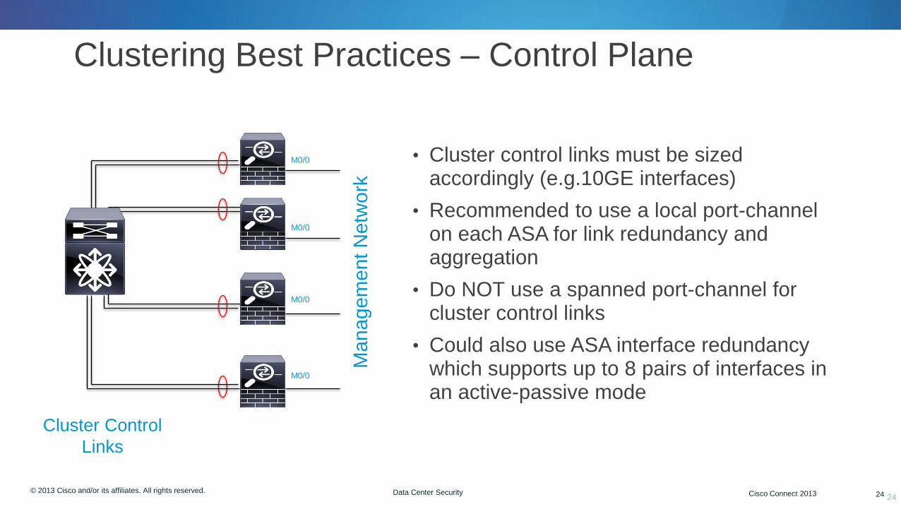
Clustering Best Practices – Control Plane
24
• Cluster control links must be sized accordingly (e.g.10GE interfaces)
• Recommended to use a local port-channel on each ASA for link redundancy and aggregation
• Do NOT use a spanned port-channel for cluster control links
• Could also use ASA interface redundancy which supports up to 8 pairs of interfaces in an active-passive mode
Managem
ent N
etw
ork
Cluster Control
Links
M0/0
M0/0
M0/0
M0/0
© 2012 Cisco and/or its affiliates. All rights reserved. Cisco Connect 25 © 2013 Cisco and/or its affiliates. All rights reserved. Cisco Connect 2013 25 Data Center Security
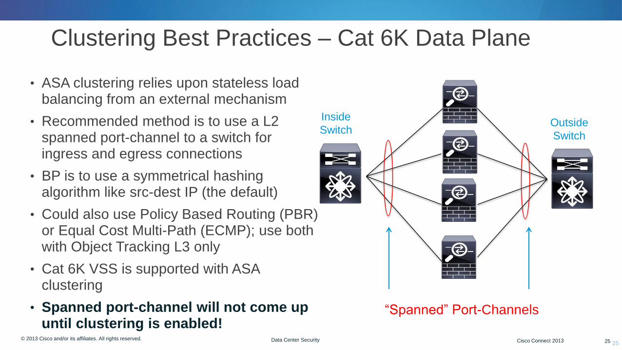
Clustering Best Practices – Cat 6K Data Plane
25
Inside
Switch Outside
Switch
• ASA clustering relies upon stateless load balancing from an external mechanism
• Recommended method is to use a L2 spanned port-channel to a switch for ingress and egress connections
• BP is to use a symmetrical hashing algorithm like src-dest IP (the default)
• Could also use Policy Based Routing (PBR) or Equal Cost Multi-Path (ECMP); use both with Object Tracking L3 only
• Cat 6K VSS is supported with ASA clustering
• Spanned port-channel will not come up until clustering is enabled!
“Spanned” Port-Channels
© 2012 Cisco and/or its affiliates. All rights reserved. Cisco Connect 26 © 2013 Cisco and/or its affiliates. All rights reserved. Cisco Connect 2013 26 Data Center Security
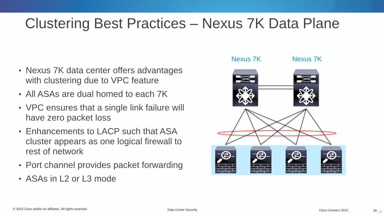
Clustering Best Practices – Nexus 7K Data Plane
26
Nexus 7K
• Nexus 7K data center offers advantages with clustering due to VPC feature
• All ASAs are dual homed to each 7K
• VPC ensures that a single link failure will have zero packet loss
• Enhancements to LACP such that ASA cluster appears as one logical firewall to rest of network
• Port channel provides packet forwarding
• ASAs in L2 or L3 mode
Nexus 7K

© 2012 Cisco and/or its affiliates. All rights reserved. Cisco Connect 27 © 2013 Cisco and/or its affiliates. All rights reserved. Cisco Connect 2013 27 Data Center Security
TCP Session: Symmetric Traffic Flow
• State replication from Owner to Director, also serves as failover message to provide redundancy should Owner fail
• Director is selected per connection using consistent hashing algorithm
• Director will act as backup should Owner fail
Insid
e N
etw
ork
Outs
ide N
etw
ork
Owner
SYN
Client Server
SYN/ACK SYN/ACK SYN
Member
1. State
update
Director
© 2012 Cisco and/or its affiliates. All rights reserved. Cisco Connect 28 © 2013 Cisco and/or its affiliates. All rights reserved. Cisco Connect 2013 28 Data Center Security
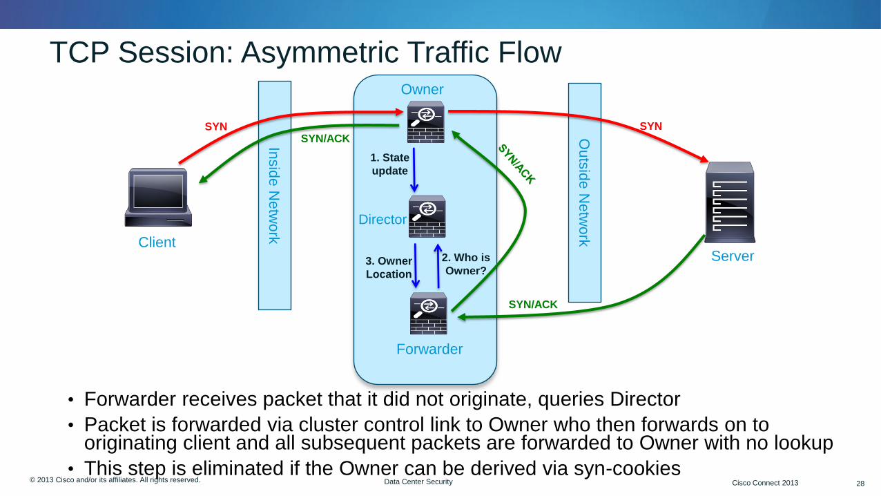
TCP Session: Asymmetric Traffic Flow
• Forwarder receives packet that it did not originate, queries Director
• Packet is forwarded via cluster control link to Owner who then forwards on to originating client and all subsequent packets are forwarded to Owner with no lookup
• This step is eliminated if the Owner can be derived via syn-cookies
Insid
e N
etw
ork
Outs
ide N
etw
ork
Owner
Director
SYN
Client Server
SYN/ACK
1. State
update
SYN/ACK SYN
Forwarder
2. Who is
Owner? 3. Owner
Location

© 2012 Cisco and/or its affiliates. All rights reserved. Cisco Connect 29 © 2013 Cisco and/or its affiliates. All rights reserved. Cisco Connect 2013 29 Data Center Security
FW+IPS Clustering with ASA 5585 Chassis
• Clustering is supported 5585s which also
support IPS module on top slot
• Leverage ASA Clustering technology for :
• Traffic load-balancing
• Traffic Symmetry
• High availability
• Caveats
• Every module is managed individually
• No “Cluster” event correlation
Clu
ste
r C
ontr
ol Lin
k
© 2013 Cisco and/or its affiliates. All rights reserved. Cisco Connect 30
Threat Visibility: NetFlow
© 2012 Cisco and/or its affiliates. All rights reserved. Cisco Connect 31 © 2013 Cisco and/or its affiliates. All rights reserved. Cisco Connect 2013 31 Data Center Security
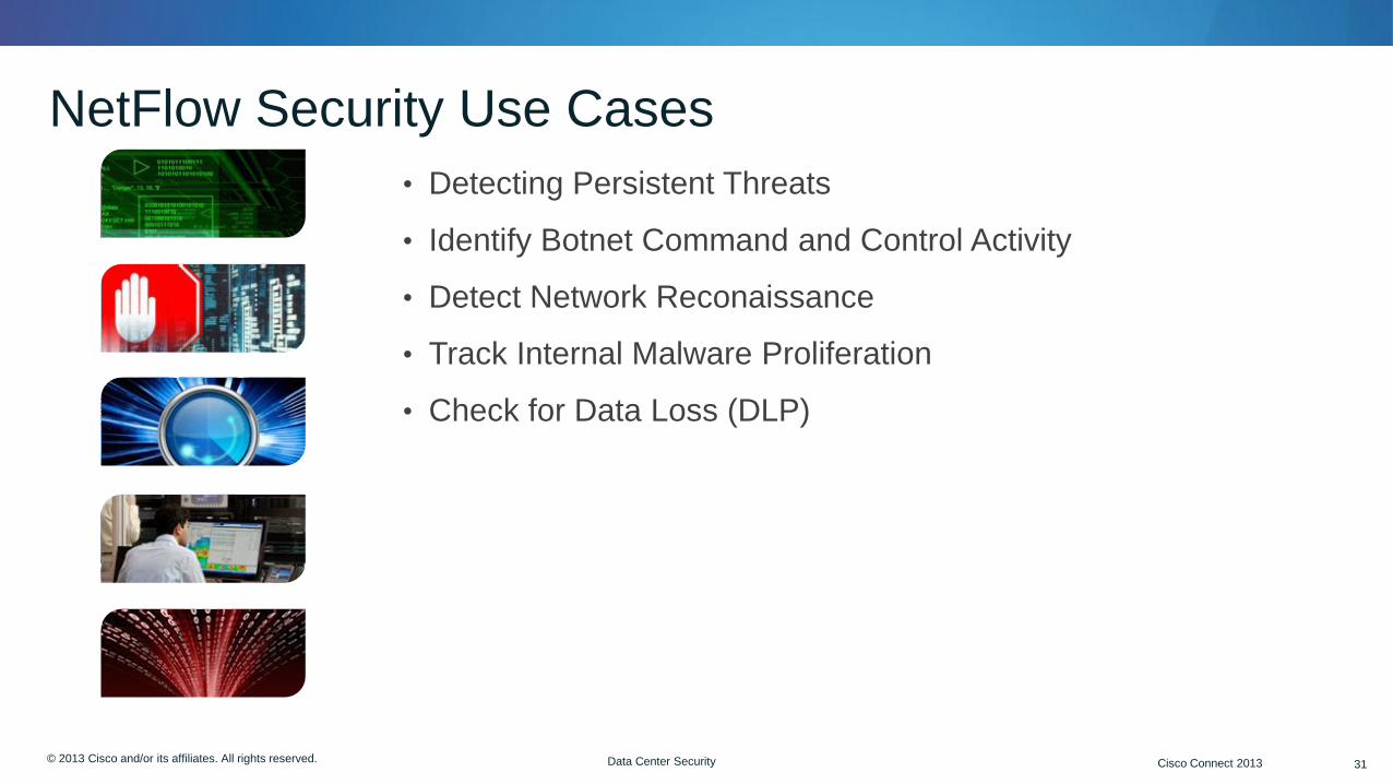
NetFlow Security Use Cases
• Detecting Persistent Threats
• Identify Botnet Command and Control Activity
• Detect Network Reconaissance
• Track Internal Malware Proliferation
• Check for Data Loss (DLP)

© 2012 Cisco and/or its affiliates. All rights reserved. Cisco Connect 32 © 2013 Cisco and/or its affiliates. All rights reserved. Cisco Connect 2013 32 Data Center Security
Netflow Overview
• Netflow was created by Cisco over 30 years ago as a flow accounting tool
• If packet capture is like a wiretap then NetFlow is like a phone bill
• We can learn a lot from studying the phone bill!
• Today many devices support line rate Netflow (Catalyst family 15.0) while the Nexus 7K supports “Flexible” Netflow
• ASA firewall has supported NSEL (Netflow Secure Event Logging) for many years
• NSEL has three options: Track flows as they are built, torn down, updated or denied
• Many vendors take in NetFlow data--Lancope, Arbor, Plixer are a few
• Cisco OEM’s Lancope’s StealthWatch as Cybersecurity Threat Defense (CTD)
32
© 2012 Cisco and/or its affiliates. All rights reserved. Cisco Connect 33 © 2013 Cisco and/or its affiliates. All rights reserved. Cisco Connect 2013 33 Data Center Security
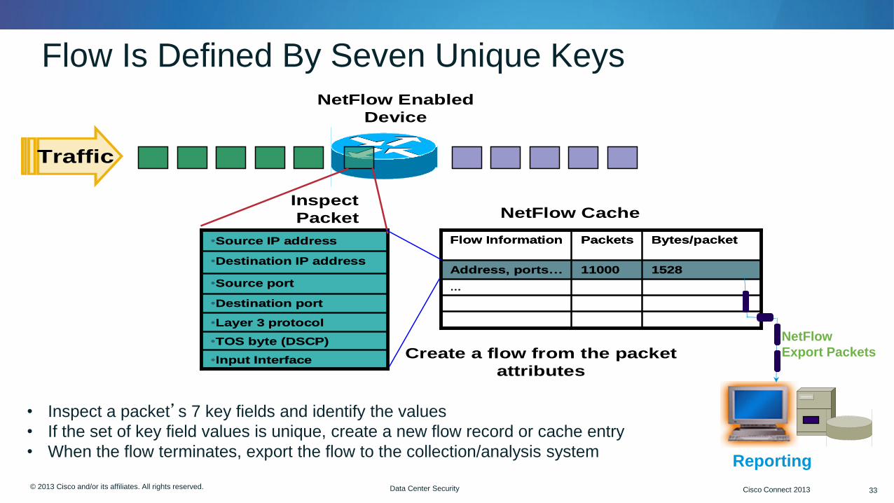
Flow Is Defined By Seven Unique Keys NetFlow Enabled
Device
Traffic
•Input Interface
•TOS byte (DSCP)
•Layer 3 protocol
•Destination port
•Source port
•Destination IP address
•Source IP address
•Input Interface
•TOS byte (DSCP)
•Layer 3 protocol
•Destination port
•Source port
•Destination IP address
•Source IP address
Create a flow from the packet
attributes
…
152811000Address, ports…
Bytes/packetPacketsFlow Information
…
152811000Address, ports…
Bytes/packetPacketsFlow Information
NetFlow CacheInspect
Packet
NetFlow
Export Packets
Reporting
• Inspect a packet’s 7 key fields and identify the values
• If the set of key field values is unique, create a new flow record or cache entry
• When the flow terminates, export the flow to the collection/analysis system

© 2012 Cisco and/or its affiliates. All rights reserved. Cisco Connect 34 © 2013 Cisco and/or its affiliates. All rights reserved. Cisco Connect 2013 34 Data Center Security
Cyber Threat Defense Solution Components
34
Cisco Network
StealthWatch FlowCollector
StealthWatch Management
Console
NetFlow
Users/Devices
Cisco ISE
NetFlow
StealthWatch FlowReplicator
Other tools/collecto
rs https
https
NBAR NSEL
NGA (NetFlow Generating
Appliance)
© 2012 Cisco and/or its affiliates. All rights reserved. Cisco Connect 35 © 2013 Cisco and/or its affiliates. All rights reserved. Cisco Connect 2013 35 Data Center Security
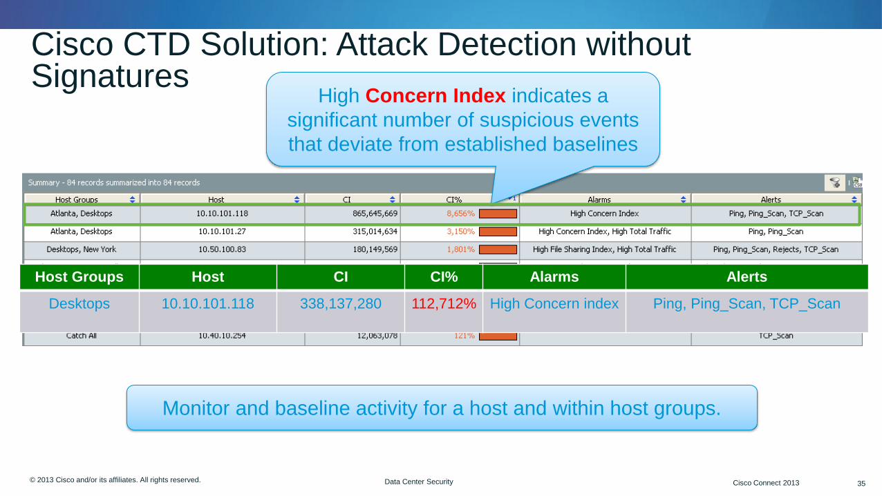
Cisco CTD Solution: Attack Detection without Signatures
High Concern Index indicates a
significant number of suspicious events
that deviate from established baselines
Host Groups Host CI CI% Alarms Alerts
Desktops 10.10.101.118 338,137,280 112,712% High Concern index Ping, Ping_Scan, TCP_Scan
Monitor and baseline activity for a host and within host groups.

© 2012 Cisco and/or its affiliates. All rights reserved. Cisco Connect 36 © 2013 Cisco and/or its affiliates. All rights reserved. Cisco Connect 2013 36 Data Center Security
1. Infected host opens connection from inside
Detecting Command and Control
36
Devices
Management
StealthWatch FlowCollector
StealthWatch Management
Console Cisco ISE
3. Infrastructure generates a record of the communication using NetFlow
5. Contextual information added to NetFlow analysis
6. Concern Index increased Host Lock Violation alarm triggered
2. Commands are sent in return traffic
NetFlow Capable
4. Collection and analysis of NetFlow data
Internal Network

© 2012 Cisco and/or its affiliates. All rights reserved. Cisco Connect 37 © 2013 Cisco and/or its affiliates. All rights reserved. Cisco Connect 2013 37 Data Center Security
Detecting Command and Control
37
Alarm indicating
communication with known
BotNet Controllers
IP Address Source user
name
Policy that
triggered
alarm
Policy Start
Active
Time
Alarms Source Source Host
Groups
Source
User Name
Target Target Host
Group
Inside
Hosts
Jan 27,
2012
Host Lock
Violation
10.35.88.171 Remote VPN Bob ZeusServer.com Zeus BotNet
Controllers

© 2013 Cisco and/or its affiliates. All rights reserved. Cisco Connect 38
Virtualized Security Nexus 1000V

© 2012 Cisco and/or its affiliates. All rights reserved. Cisco Connect 39 © 2013 Cisco and/or its affiliates. All rights reserved. Cisco Connect 2013 39 Data Center Security
Common Virtualization Concerns
39
• Policy Enforcement
• Applied at physical server—not the individual VM
• Impossible to enforce policy for VMs in motion
• Operations and Management
• Lack of VM visibility, accountability, and consistency
• Difficult management model and inability to effectively troubleshoot
• Roles and Responsibilities
• Muddled ownership as server admin must configure virtual network
• Organizational redundancy creates compliance challenges
• Machine Segmentation
• Server and application isolation on same physical server
• No separation between compliant and non-compliant systems
Hypervisor
Roles and
Responsibiliti
es
Isolation and
Segmentation
Management
and Monitoring
© 2012 Cisco and/or its affiliates. All rights reserved. Cisco Connect 40 © 2013 Cisco and/or its affiliates. All rights reserved. Cisco Connect 2013 40 Data Center Security
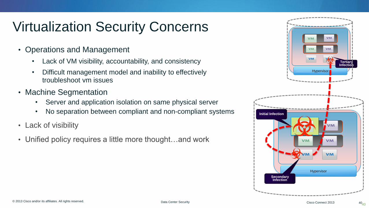
Virtualization Security Concerns
40
• Operations and Management
• Lack of VM visibility, accountability, and consistency
• Difficult management model and inability to effectively troubleshoot vm issues
• Machine Segmentation
• Server and application isolation on same physical server
• No separation between compliant and non-compliant systems
• Lack of visibility
• Unified policy requires a little more thought…and work
Hypervisor
Initial Infection
Secondary Infection
Hypervisor
Tertiary Infection
© 2012 Cisco and/or its affiliates. All rights reserved. Cisco Connect 41 © 2013 Cisco and/or its affiliates. All rights reserved. Cisco Connect 2013 41 Data Center Security
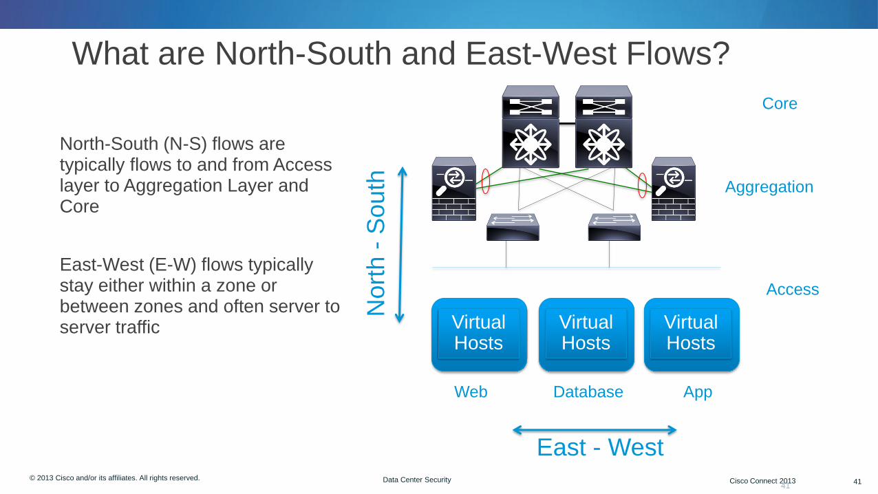
What are North-South and East-West Flows?
• North-South (N-S) flows are typically flows to and from Access layer to Aggregation Layer and Core
• East-West (E-W) flows typically stay either within a zone or between zones and often server to server traffic
41
Web App
Access
Aggregation
Core
Database
East - West
Nort
h -
South
Virtual Hosts
Virtual Hosts
Virtual Hosts
© 2012 Cisco and/or its affiliates. All rights reserved. Cisco Connect 42 © 2013 Cisco and/or its affiliates. All rights reserved. Cisco Connect 2013 42 Data Center Security 42
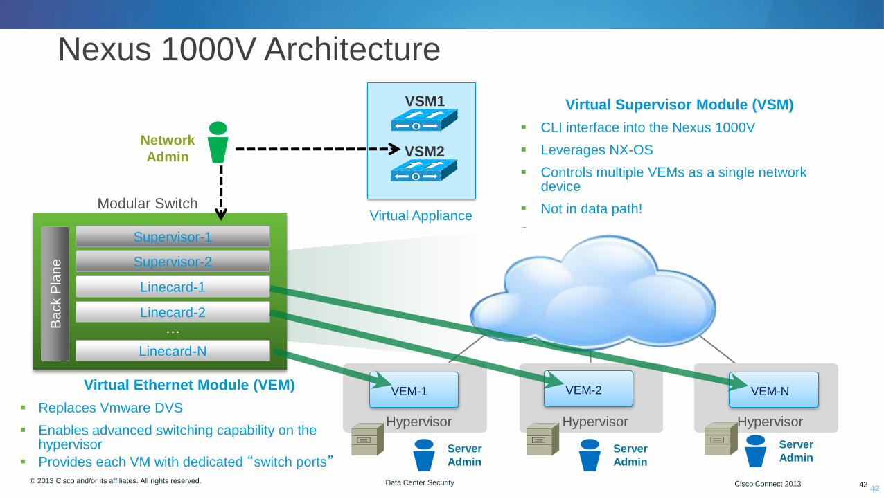
Nexus 1000V Architecture
42
Hypervisor Hypervisor Hypervisor
Modular Switch
…
Linecard-N
Supervisor-1
Supervisor-2
Linecard-1
Linecard-2
Ba
ck P
lan
e
VEM-N VEM-1 VEM-2
VSM1
VSM2 Network
Admin
Virtual Appliance
Virtual Supervisor Module (VSM)
CLI interface into the Nexus 1000V
Leverages NX-OS
Controls multiple VEMs as a single network device
Not in data path!
Virtual Ethernet Module (VEM)
Replaces Vmware DVS
Enables advanced switching capability on the hypervisor
Provides each VM with dedicated “switch ports” Server
Admin
Server
Admin
Server
Admin
© 2012 Cisco and/or its affiliates. All rights reserved. Cisco Connect 43 © 2013 Cisco and/or its affiliates. All rights reserved. Cisco Connect 2013 43 Data Center Security
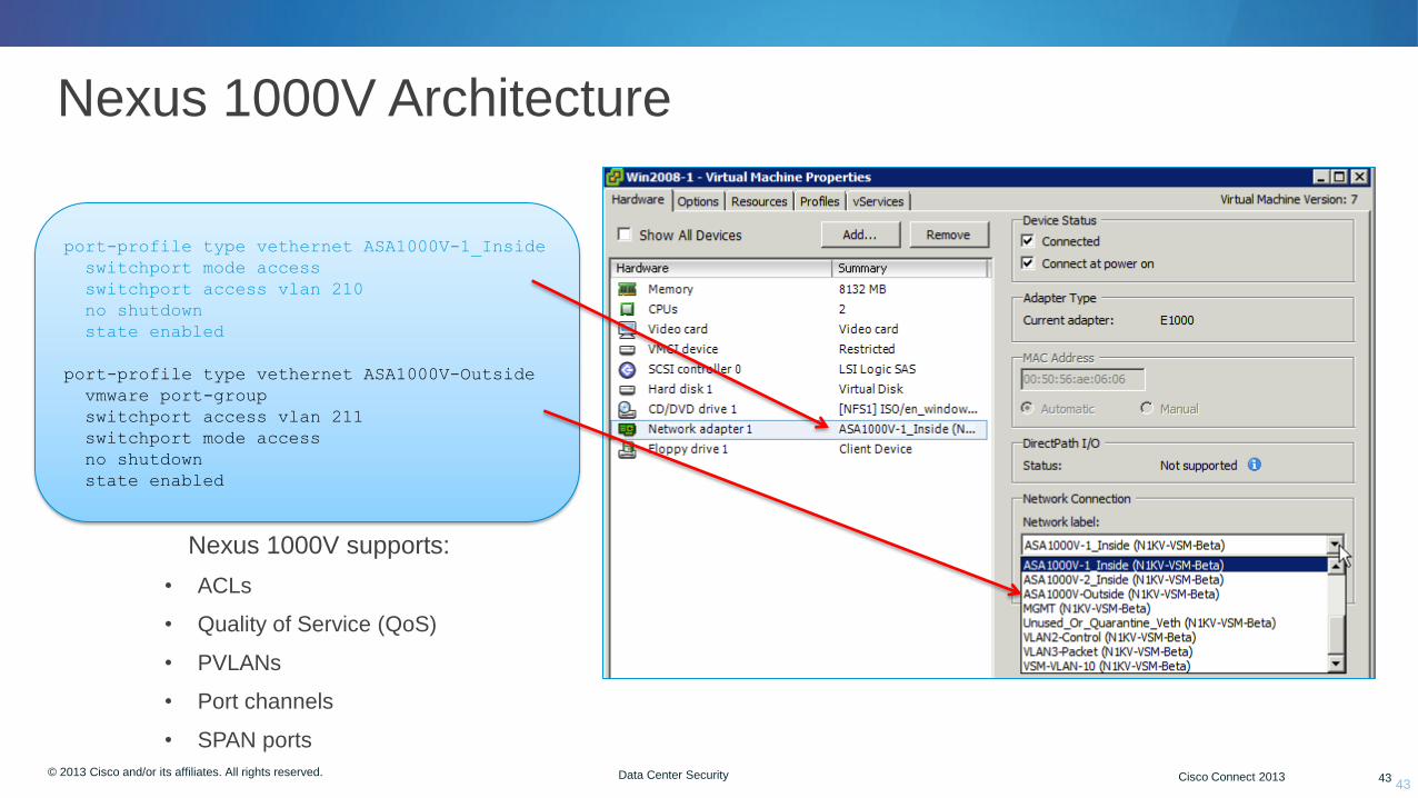
Nexus 1000V Architecture
43
port-profile type vethernet ASA1000V-1_Inside
switchport mode access
switchport access vlan 210
no shutdown
state enabled
port-profile type vethernet ASA1000V-Outside
vmware port-group
switchport access vlan 211
switchport mode access
no shutdown
state enabled
Nexus 1000V supports:
• ACLs
• Quality of Service (QoS)
• PVLANs
• Port channels
• SPAN ports

© 2012 Cisco and/or its affiliates. All rights reserved. Cisco Connect 44 © 2013 Cisco and/or its affiliates. All rights reserved. Cisco Connect 2013 44 Data Center Security
What is Vpath?
• vPath is the forwarding “brains” built into the Virtual Ethernet Module (VEM) of the Nexus 1000V
• It is an encapsulation that tags flows based upon attributes
• It has two main functions:
• Intelligent traffic steering
• Offload processing from virtual service nodes (VSN) to VEM
• vPath allows processing to be offloaded to Hypervisor for performance
• Currently only supported on VMWare today with future support for Hyper-V and others
• vPath is cornerstone for Cisco’s VSN delivery

© 2013 Cisco and/or its affiliates. All rights reserved. Cisco Connect 45
Virtualized Security Firewalls
© 2012 Cisco and/or its affiliates. All rights reserved. Cisco Connect 46 © 2013 Cisco and/or its affiliates. All rights reserved. Cisco Connect 2013 46 Data Center Security
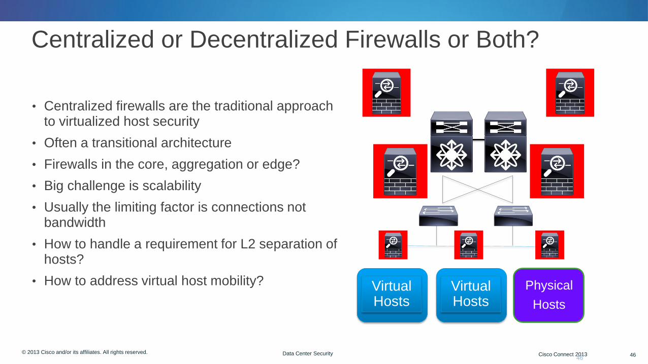
Centralized or Decentralized Firewalls or Both?
• Centralized firewalls are the traditional approach to virtualized host security
• Often a transitional architecture
• Firewalls in the core, aggregation or edge?
• Big challenge is scalability
• Usually the limiting factor is connections not bandwidth
• How to handle a requirement for L2 separation of hosts?
• How to address virtual host mobility?
46
Virtual Hosts
Virtual Hosts
Physical
Hosts
© 2012 Cisco and/or its affiliates. All rights reserved. Cisco Connect 47 © 2013 Cisco and/or its affiliates. All rights reserved. Cisco Connect 2013 47 Data Center Security
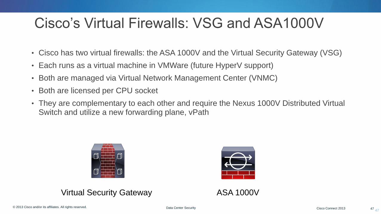
Cisco’s Virtual Firewalls: VSG and ASA1000V
• Cisco has two virtual firewalls: the ASA 1000V and the Virtual Security Gateway (VSG)
• Each runs as a virtual machine in VMWare (future HyperV support)
• Both are managed via Virtual Network Management Center (VNMC)
• Both are licensed per CPU socket
• They are complementary to each other and require the Nexus 1000V Distributed Virtual Switch and utilize a new forwarding plane, vPath
47
Virtual Security Gateway ASA 1000V
© 2012 Cisco and/or its affiliates. All rights reserved. Cisco Connect 48 © 2013 Cisco and/or its affiliates. All rights reserved. Cisco Connect 2013 48 Data Center Security
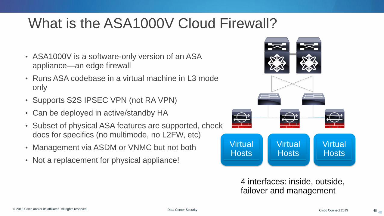
What is the ASA1000V Cloud Firewall?
• ASA1000V is a software-only version of an ASA appliance—an edge firewall
• Runs ASA codebase in a virtual machine in L3 mode only
• Supports S2S IPSEC VPN (not RA VPN)
• Can be deployed in active/standby HA
• Subset of physical ASA features are supported, check docs for specifics (no multimode, no L2FW, etc)
• Management via ASDM or VNMC but not both
• Not a replacement for physical appliance!
48
Virtual Hosts
Virtual Hosts
Virtual Hosts
4 interfaces: inside, outside, failover and management
© 2012 Cisco and/or its affiliates. All rights reserved. Cisco Connect 49 © 2013 Cisco and/or its affiliates. All rights reserved. Cisco Connect 2013 49 Data Center Security
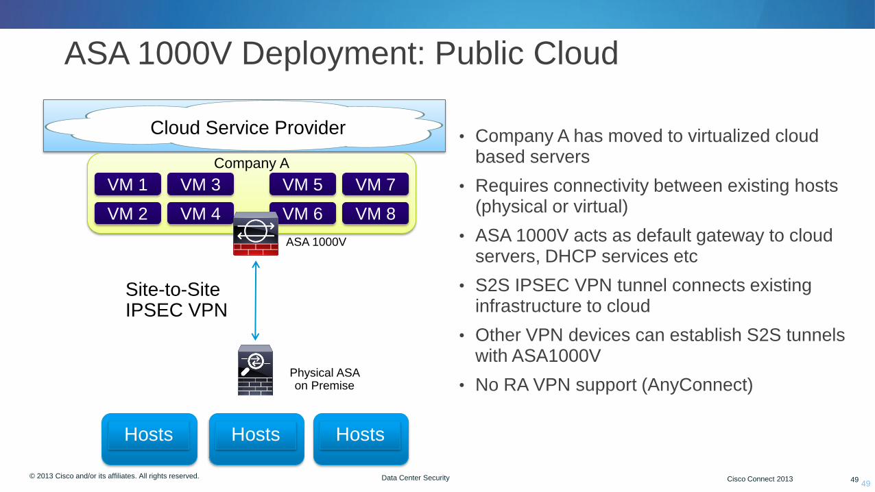
ASA 1000V Deployment: Public Cloud
49
Hosts Hosts Hosts
Cloud Service Provider
Company A
VM 1
VM 2
VM 3
VM 4
ASA 1000V
Physical ASA on Premise
Site-to-Site IPSEC VPN
VM 5
VM 6
VM 7
VM 8
• Company A has moved to virtualized cloud based servers
• Requires connectivity between existing hosts (physical or virtual)
• ASA 1000V acts as default gateway to cloud servers, DHCP services etc
• S2S IPSEC VPN tunnel connects existing infrastructure to cloud
• Other VPN devices can establish S2S tunnels with ASA1000V
• No RA VPN support (AnyConnect)
© 2012 Cisco and/or its affiliates. All rights reserved. Cisco Connect 50 © 2013 Cisco and/or its affiliates. All rights reserved. Cisco Connect 2013 50 Data Center Security
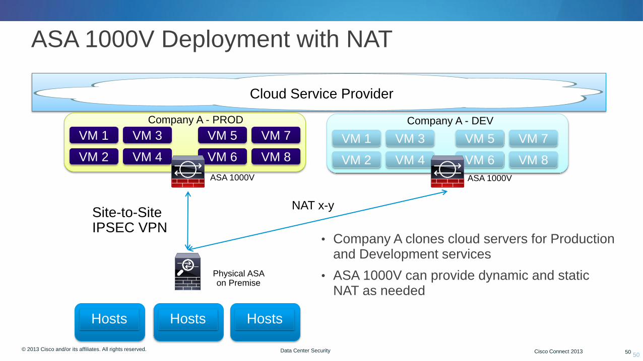
ASA 1000V Deployment with NAT
50
Hosts Hosts Hosts
Cloud Service Provider
Company A - PROD
VM 1
VM 2
VM 3
VM 4
ASA 1000V
Physical ASA on Premise
Site-to-Site IPSEC VPN
VM 5
VM 6
VM 7
VM 8
Company A - DEV
VM 1
VM 2
VM 3
VM 4
VM 5
VM 6
VM 7
VM 8
• Company A clones cloud servers for Production and Development services
• ASA 1000V can provide dynamic and static NAT as needed
NAT x-y
ASA 1000V

© 2012 Cisco and/or its affiliates. All rights reserved. Cisco Connect 51 © 2013 Cisco and/or its affiliates. All rights reserved. Cisco Connect 2013 51 Data Center Security
ASA 1000V Deployment: Internal Private Cloud
51
Zone 1 Zone 2 Zone 3
VM 1
VM 2
VM 3
VM 4
VFW 1
VM 5
VM 6
VM 7
VM 8
VFW 2 VFW 3
• Today multi context mode on ASA is used to provide firewall inspection for multi tenant and multi zone environments
• Trunks are typically used to transport zone and tenant traffic
• Challenge of E-W scale requires more firewall resources
• ASA 1000V provides edge firewall and can scale alongside E-W buildout
• Each tenant or zone gets one or more ASA 1000V
• Provides NAT and DHCP services for scale
Vzone 1 Vzone 2
Multi Context Mode ASA
© 2012 Cisco and/or its affiliates. All rights reserved. Cisco Connect 52 © 2013 Cisco and/or its affiliates. All rights reserved. Cisco Connect 2013 52 Data Center Security
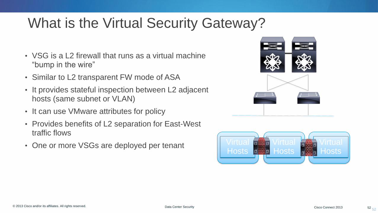
What is the Virtual Security Gateway?
• VSG is a L2 firewall that runs as a virtual machine “bump in the wire”
• Similar to L2 transparent FW mode of ASA
• It provides stateful inspection between L2 adjacent hosts (same subnet or VLAN)
• It can use VMware attributes for policy
• Provides benefits of L2 separation for East-West traffic flows
• One or more VSGs are deployed per tenant
52
Virtual Hosts
Virtual Hosts
Virtual Hosts

© 2012 Cisco and/or its affiliates. All rights reserved. Cisco Connect 53 © 2013 Cisco and/or its affiliates. All rights reserved. Cisco Connect 2013 53 Data Center Security
VM Attributes Used by VSG (Partial List)
Name Meaning Source
vm.name Name of this VM vCenter
vm.host-name Name of this ESX-host vCenter
vm.os-fullname Name of guest OS vCenter
vm.vapp-name Name of the associated
vApp
vCenter
vm.cluster-name Name of the cluster vCenter
vm.portprofile-name Name of the port-profile Port-profile
© 2012 Cisco and/or its affiliates. All rights reserved. Cisco Connect 54 © 2013 Cisco and/or its affiliates. All rights reserved. Cisco Connect 2013 54 Data Center Security
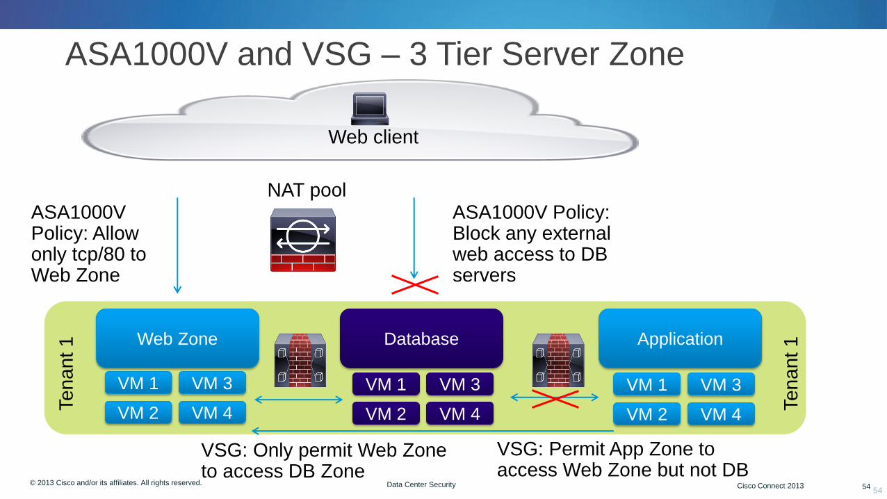
ASA1000V and VSG – 3 Tier Server Zone
54
Web Zone Database Application
VM 1
VM 2
VM 3
VM 4
VM 1
VM 2
VM 3
VM 4
VM 1
VM 2
VM 3
VM 4
NAT pool ASA1000V Policy: Block any external web access to DB servers
ASA1000V Policy: Allow only tcp/80 to Web Zone
VSG: Only permit Web Zone to access DB Zone
VSG: Permit App Zone to access Web Zone but not DB
Te
nant 1
Te
nant 1
Web client

© 2012 Cisco and/or its affiliates. All rights reserved. Cisco Connect 55 © 2013 Cisco and/or its affiliates. All rights reserved. Cisco Connect 2013 55 Data Center Security
ASA1000V and VSG Compared
ASA1000V (Edge) Virtual Security Gateway
L3 routed mode only L2 mode (transparent)
Static routes only No routing
DHCP server and client support No DHCP support
Supports site-to-site IPSEC No IPSEC support
Managed by ASDM and VNMC Managed by VNMC only
Uses ASA code, CLI, SSH Minimal config via CLI, SSH
55

© 2013 Cisco and/or its affiliates. All rights reserved. Cisco Connect 56
Virtualized Security Cloud Services Router
© 2012 Cisco and/or its affiliates. All rights reserved. Cisco Connect 57 © 2013 Cisco and/or its affiliates. All rights reserved. Cisco Connect 2013 57 Data Center Security 57
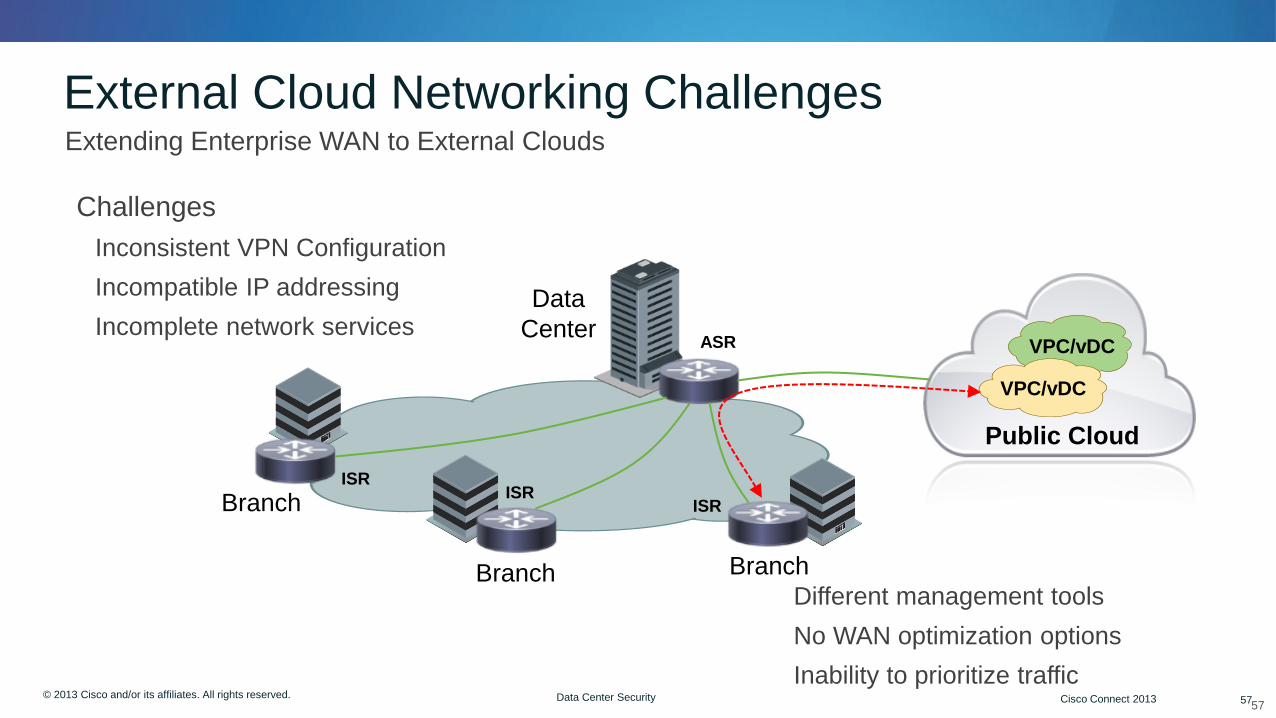
External Cloud Networking Challenges
• Challenges
Inconsistent VPN Configuration
Incompatible IP addressing
Incomplete network services
• Extending Enterprise WAN to External Clouds
Different management tools
No WAN optimization options
Inability to prioritize traffic
Branch
ISR Branch ISR
Branch
ISR
Data
Center ASR
Public Cloud
VPC/vDC
VPC/vDC

© 2012 Cisco and/or its affiliates. All rights reserved. Cisco Connect 58 © 2013 Cisco and/or its affiliates. All rights reserved. Cisco Connect 2013 58 Data Center Security
CSR 1000v • Cisco IOS XE Software in Virtual Form-factor
• Cisco IOS XE Cloud Edition
• Selected feature set of Cisco IOS XE
• Virtual Route Processor (RP)
• Virtual Forwarding Processor (FP)
• Virtual Private Cloud/Data Center Gateway
• Optimized for single tenant use cases
• Agnostic to Other Infrastructure Elements
• Hypervisor agnostic
• Virtual switch agnostic
• Server agnostic
Server
Hypervisor Virtual Switch
VPC/vDC
OS
App
CSR 1000v
OS
App
© 2012 Cisco and/or its affiliates. All rights reserved. Cisco Connect 59 © 2013 Cisco and/or its affiliates. All rights reserved. Cisco Connect 2013 59 Data Center Security
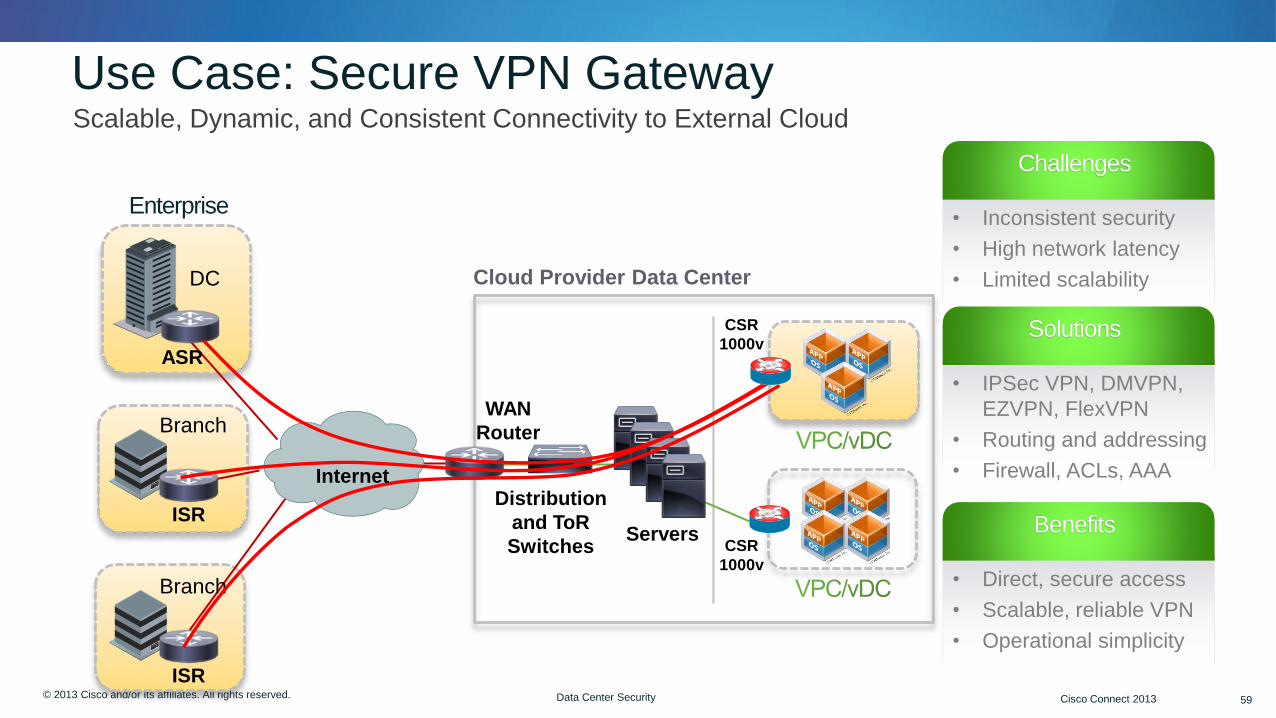
Use Case: Secure VPN Gateway • Scalable, Dynamic, and Consistent Connectivity to External Cloud
CSR
1000v
Branch
ISR
WAN
Router
Distribution
and ToR
Switches Servers
DC
ASR
CSR
1000v
Cloud Provider Data Center
Branch
ISR
Enterprise
Challenges
• Inconsistent security
• High network latency
• Limited scalability
Solutions
• IPSec VPN, DMVPN,
EZVPN, FlexVPN
• Routing and addressing
• Firewall, ACLs, AAA
Benefits
• Direct, secure access
• Scalable, reliable VPN
• Operational simplicity
Internet
© 2012 Cisco and/or its affiliates. All rights reserved. Cisco Connect 60 © 2013 Cisco and/or its affiliates. All rights reserved. Cisco Connect 2013 60 Data Center Security
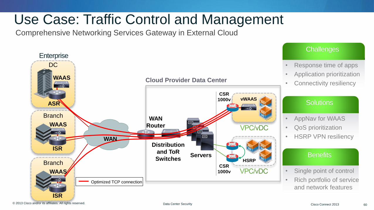
Use Case: Traffic Control and Management • Comprehensive Networking Services Gateway in External Cloud
CSR
1000v
WAN
Router
Distribution
and ToR
Switches Servers
CSR
1000v
Cloud Provider Data Center
Enterprise
Optimized TCP connection
Challenges
• Response time of apps
• Application prioritization
• Connectivity resiliency
Solutions
• AppNav for WAAS
• QoS prioritization
• HSRP VPN resiliency
Benefits
• Single point of control
• Rich portfolio of service
and network features
vWAAS
HSRP
Branch
ISR
WAAS
Branch
ISR
WAAS
DC
ASR
WAAS
WAN
© 2013 Cisco and/or its affiliates. All rights reserved. Cisco Connect 61
TrustSec in the DC Security Group Tags
© 2012 Cisco and/or its affiliates. All rights reserved. Cisco Connect 62 © 2013 Cisco and/or its affiliates. All rights reserved. Cisco Connect 2013 62 Data Center Security 62
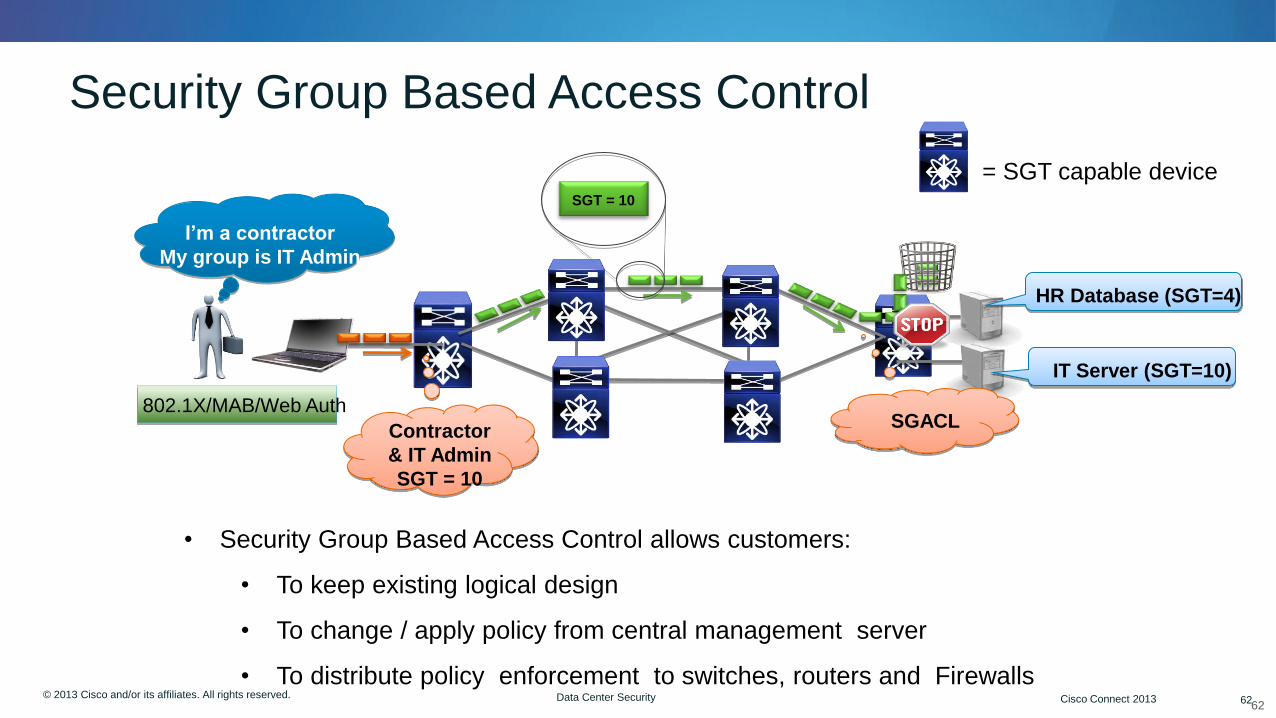
Security Group Based Access Control
SGACL
• Security Group Based Access Control allows customers:
• To keep existing logical design
• To change / apply policy from central management server
• To distribute policy enforcement to switches, routers and Firewalls
802.1X/MAB/Web Auth
HR Database (SGT=4)
IT Server (SGT=10)
I’m a contractor
My group is IT Admin
Contractor
& IT Admin
SGT = 10
SGT = 10
= SGT capable device
© 2012 Cisco and/or its affiliates. All rights reserved. Cisco Connect 63 © 2013 Cisco and/or its affiliates. All rights reserved. Cisco Connect 2013 63 Data Center Security
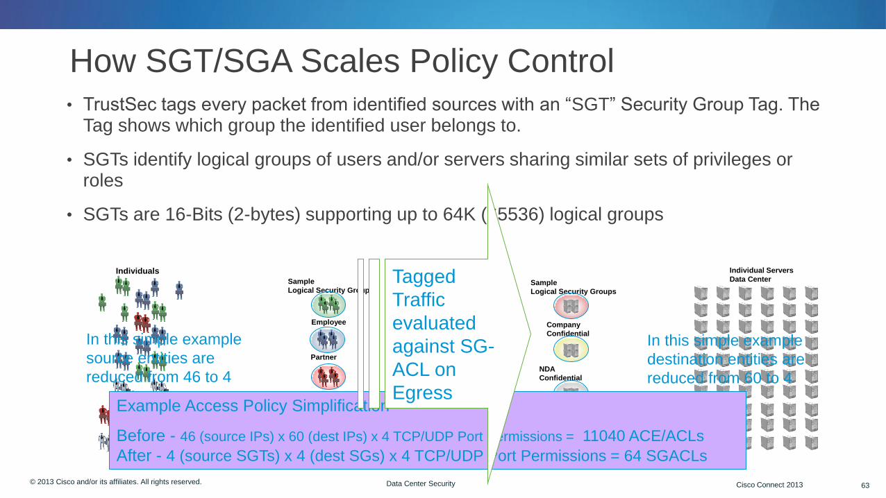
How SGT/SGA Scales Policy Control • TrustSec tags every packet from identified sources with an “SGT” Security Group Tag. The
Tag shows which group the identified user belongs to.
• SGTs identify logical groups of users and/or servers sharing similar sets of privileges or roles
• SGTs are 16-Bits (2-bytes) supporting up to 64K (65536) logical groups
Individuals
Sample
Logical Security Groups
Contractor
Employee
Partner
Guest
Unknown
Sample
Logical Security Groups
Individual Servers
Data Center
Sensitive
Company
Confidential
NDA
Confidential
General Access
In this simple example
source entities are
reduced from 46 to 4
In this simple example
destination entities are
reduced from 60 to 4
Example Access Policy Simplification
Before - 46 (source IPs) x 60 (dest IPs) x 4 TCP/UDP Port Permissions = 11040 ACE/ACLs
After - 4 (source SGTs) x 4 (dest SGs) x 4 TCP/UDP Port Permissions = 64 SGACLs
Tagged
Traffic
evaluated
against SG-
ACL on
Egress

© 2012 Cisco and/or its affiliates. All rights reserved. Cisco Connect 64 © 2013 Cisco and/or its affiliates. All rights reserved. Cisco Connect 2013 64 Data Center Security
Why Security Group Tags?
64
Source: Ken Hook
Traditional Discretionary Access
Control Individuals Resources
Server 1
Permissions
Server 2
Server 3
Challenges
• Leads to ACE explosion (# of sources) X (# of Destinations) X (# of permissions) = #
ACEs
• IP-address based ACLs are challenging
- Changes in addressing schemes
- Use of DHCP
- Proliferation of Wireless LAN devices
• Assumes relatively static placement of users/resources
TrustSec SGT Addresses these challenges via:
• Security Group Tags (SGT) provide a level of abstraction, reducing the
ACL/ACE proliferation dramatically
• Simplified Policy Definition – Security Groups are logical and Topology
Independent
• Portable Policy – Security Groups allows for mobility of users and resources
access-list 101 permit tcp S1/32 D1/32 eq http
access-list 101 permit tcp S1/32 D1/32 eq https
access-list 101 permit tcp S1/32 D2/32 eq ftp
access-list 101 permit tcp S1/32 D2/32 eq http
access-list 101 permit tcp S1/32 D2/32 eq https
access-list 101 permit tcp S1/32 D2/32 eq ftp
access-list 101 permit udp S1/32 D1/32 gt 1023
access-list 101 permit udp S1/32 D2/32 gt 1023
Access List for S1
Individuals
Resources
Security Groups
Partners
Employee
Contractor
Internet
Confidential
Special
Projects
Authz Rules Authz Rules
Authz Rules Authz Rules
Security Groups
Source Destination
Guest/Unknown
Print / Copy
Employee
Outside US
Access Rules
Access Rules
Source 1

© 2012 Cisco and/or its affiliates. All rights reserved. Cisco Connect 65 © 2013 Cisco and/or its affiliates. All rights reserved. Cisco Connect 2013 65 Data Center Security 65
How To Create SGT Policy
Doctor (SGT 7)
IT Admin (SGT 5)
IT Portal
(SGT 4)
Public Portal
(SGT 8)
Internal Portal
(SGT 9)
Patient Record DB
(SGT 10)
Destination
SGT
Source
SGT
Web Web No Access Web
File Share
Web
SSH
RDP
File Share
Web
SSH
RDP
File Share
Full Access
SSH
RDP
File Share
permit tcp dst eq 443 permit tcp dst eq 80 permit tcp dst eq 22 permit tcp dst eq 3389 permit tcp dst eq 135 permit tcp dst eq 136 permit tcp dst eq 137 permit tcp dst eq 138 permit tcp des eq 139 deny ip
IT Maintenance ACL

© 2013 Cisco and/or its affiliates. All rights reserved. Cisco Connect 66
Secure Data Center Validated Architectures

© 2012 Cisco and/or its affiliates. All rights reserved. Cisco Connect 67 © 2013 Cisco and/or its affiliates. All rights reserved. Cisco Connect 2013 67 Data Center Security
Why Validation Matters
• We test to validate that certains systems coexist and function as expected
• Testing also exposes weaknesses to a given design or architecture
• Results are documented and shared to customers, partners and other entitites
• Customer facing labs like Customer Proof of Concept (CPOC) and ECATS (Enhanced Customer Aligned Testing Service)
• Internal labs like the Virtualized Multiservice Data Center (VMDC) lab on Cisco’s campus in Research Triangle Park, NC http://www.cisco.com/go/vmdc
• VMDC mission is to build a reference architecture for secure, scalable cloud and traditional DCs
• Latest architecture version is 3.01

© 2012 Cisco and/or its affiliates. All rights reserved. Cisco Connect 68 © 2013 Cisco and/or its affiliates. All rights reserved. Cisco Connect 2013 68 Data Center Security
vPC Peer-link
vPC9 vPC10
7k-1 AGG-VDC
7k-2 AGG-VDC
7k-1 Core-VDC
7k-2 Core-VDC
(L2 Boundary)
VMNIC #3 VMNIC #2 VMNIC #3 VMNIC#2
vPC11
vPC111
vPC66 vPC67
Secure DC Architecture 1.0
• Virtual Device Contexts (VDC) used to create virtual core and aggregation layer
• Each ASA firewall is connected to aggregation switch over a dedicated vPC domain
• Each firewall is deployed in transparent mode. Offers easiest integration with existing addressing and flows and additional services (load balancing, etc).
• Server gateway location is critical design decision
• ASAs can be in A/S or A/A

s
Core 3 Core 4
Congo
AGG 1
VDC 2
Nigeria
AGG 2
VDC 2
OTV OTV
ASA4
Core 1 Core 2
AGG 1 AGG 2
OTV OTV
ASA1 ASA2 ASA3
OTV
Data Center 1 Data Center 2
20.3.1.0/24 .
2
.1
Core 3
OTV 3
20.4.1.0/24 .
2
.1
Core 4
OTV 4
20.1.1.0/24 .
2
.1
Core 1
OTV 1
20.2.1.0/24 .
2
.1
Core 2
OTV 2
OTV Site VLAN 700
vPC 10 vPC 11
OTV Site VLAN 700
vPC 25 vPC 26
Master
Secure DC Architecture 2.0 with Firewall Clustering Clustering over OTV
© 2012 Cisco and/or its affiliates. All rights reserved. Cisco Connect 70 © 2013 Cisco and/or its affiliates. All rights reserved. Cisco Connect 2013 70 Data Center Security
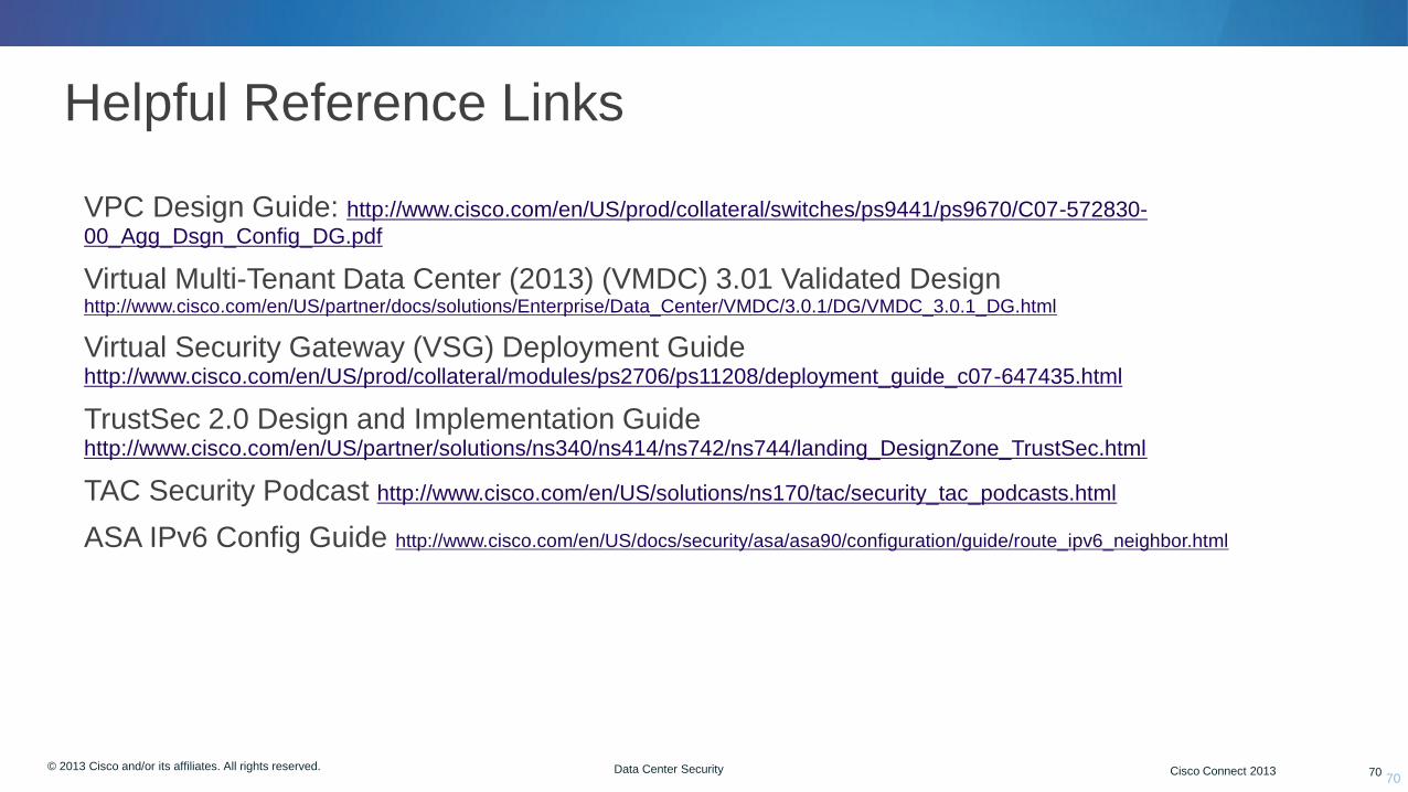
Helpful Reference Links
• VPC Design Guide: http://www.cisco.com/en/US/prod/collateral/switches/ps9441/ps9670/C07-572830-
00_Agg_Dsgn_Config_DG.pdf
• Virtual Multi-Tenant Data Center (2013) (VMDC) 3.01 Validated Design http://www.cisco.com/en/US/partner/docs/solutions/Enterprise/Data_Center/VMDC/3.0.1/DG/VMDC_3.0.1_DG.html
• Virtual Security Gateway (VSG) Deployment Guide http://www.cisco.com/en/US/prod/collateral/modules/ps2706/ps11208/deployment_guide_c07-647435.html
• TrustSec 2.0 Design and Implementation Guide http://www.cisco.com/en/US/partner/solutions/ns340/ns414/ns742/ns744/landing_DesignZone_TrustSec.html
• TAC Security Podcast http://www.cisco.com/en/US/solutions/ns170/tac/security_tac_podcasts.html
• ASA IPv6 Config Guide http://www.cisco.com/en/US/docs/security/asa/asa90/configuration/guide/route_ipv6_neighbor.html
70
Complete Your Paper “Session Evaluation”
Give us your feedback and you could win
1 of 2 fabulous prizes in a random draw.
Complete and return your paper
evaluation form to the room attendant
as you leave this session.
Winners will be announced today.
You must be present to win!
..visit them at BOOTH# 100
© 2012 Cisco and/or its affiliates. All rights reserved. Cisco Connect 72
Thank you.

© 2013 Cisco and/or its affiliates. All rights reserved. Cisco Connect 73
Appendix Additional Slides

© 2012 Cisco and/or its affiliates. All rights reserved. Cisco Connect 74 © 2013 Cisco and/or its affiliates. All rights reserved. Cisco Connect 2013 74 Data Center Security
Overlay Transport Virtualization (OTV)
74
O
V
Overlay - A solution that is independent of the
infrastructure technology and services, flexible
over various inter-connect facilities
Transport - Transporting services for layer 2 and
layer 3 Ethernet and IP traffic
Virtualization - Provides virtual stateless multi-
access connections, which can be further
partitioned into VPNs, VRFs, VLANs
T
OTV delivers a virtual L2 transport over any L3 Infrastructure

© 2012 Cisco and/or its affiliates. All rights reserved. Cisco Connect 75 © 2013 Cisco and/or its affiliates. All rights reserved. Cisco Connect 2013 75 Data Center Security
Transport
Infrastructure
OTV OTV OTV OTV
MAC 1 MAC 3
Layer 2
Lookup
5 MAC 1 MAC 3 Layer 2
Lookup
1 Encap
2 Decap
4
MAC 1 MAC 3 West
Site MAC 1
MAC 3 East
Site
1. Layer 2 lookup on the destination MAC. MAC 3 is
reachable through IP B
2. The Edge Device encapsulates the frame
3. The transport delivers the packet to the Edge
Device on site East
4. The Edge Device on site East receives and
decapsulates the packet
5. Layer 2 lookup on the original frame. MAC 3 is a
local MAC
6. The frame is delivered to the destination
3
6
IP A IP B
MAC TABLE
VLAN MAC IF
100 MAC 1 Eth 2
100 MAC 2 Eth 1
100 MAC 3 IP B
100 MAC 4 IP B
MAC TABLE
VLAN MAC IF
100 MAC 1 IP A
100 MAC 2 IP A
100 MAC 3 Eth 3
100 MAC 4 Eth 4
IP A IP B MAC 1 MAC 3 IP A IP B MAC 1 MAC 3
OTV
75
• Extending Layer 2
© 2012 Cisco and/or its affiliates. All rights reserved. Cisco Connect 76 © 2013 Cisco and/or its affiliates. All rights reserved. Cisco Connect 2013 76 Data Center Security
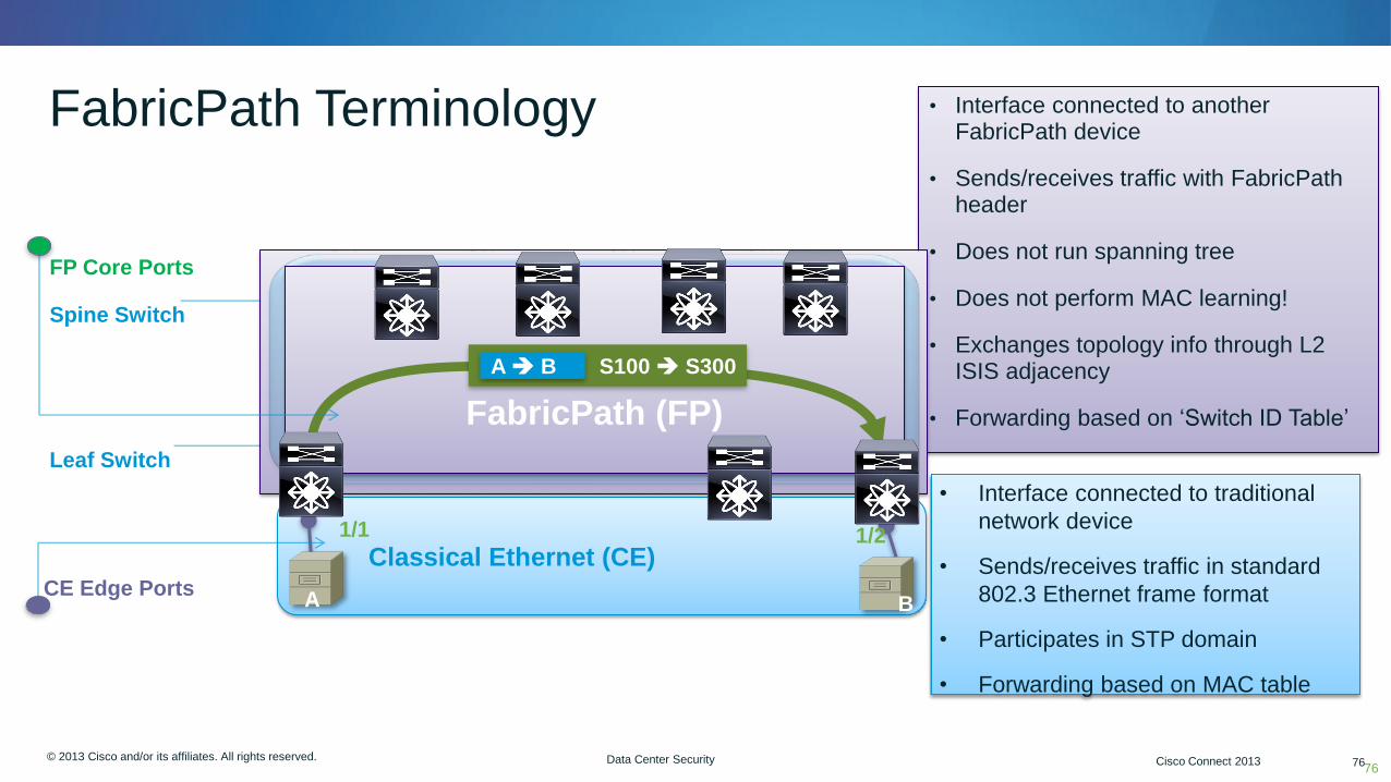
FabricPath Terminology
76
• Interface connected to another FabricPath device
• Sends/receives traffic with FabricPath header
• Does not run spanning tree
• Does not perform MAC learning!
• Exchanges topology info through L2 ISIS adjacency
• Forwarding based on ‘Switch ID Table’
CE Edge Ports
FP Core Ports
Spine Switch
Leaf Switch
Classical Ethernet (CE)
S10 S20 S30 S40
S100 S200 S300
1/1 1/2
FabricPath (FP)
S100 S300 A B
A B
• Interface connected to traditional
network device
• Sends/receives traffic in standard
802.3 Ethernet frame format
• Participates in STP domain
• Forwarding based on MAC table
© 2012 Cisco and/or its affiliates. All rights reserved. Cisco Connect 77 © 2013 Cisco and/or its affiliates. All rights reserved. Cisco Connect 2013 77 Data Center Security
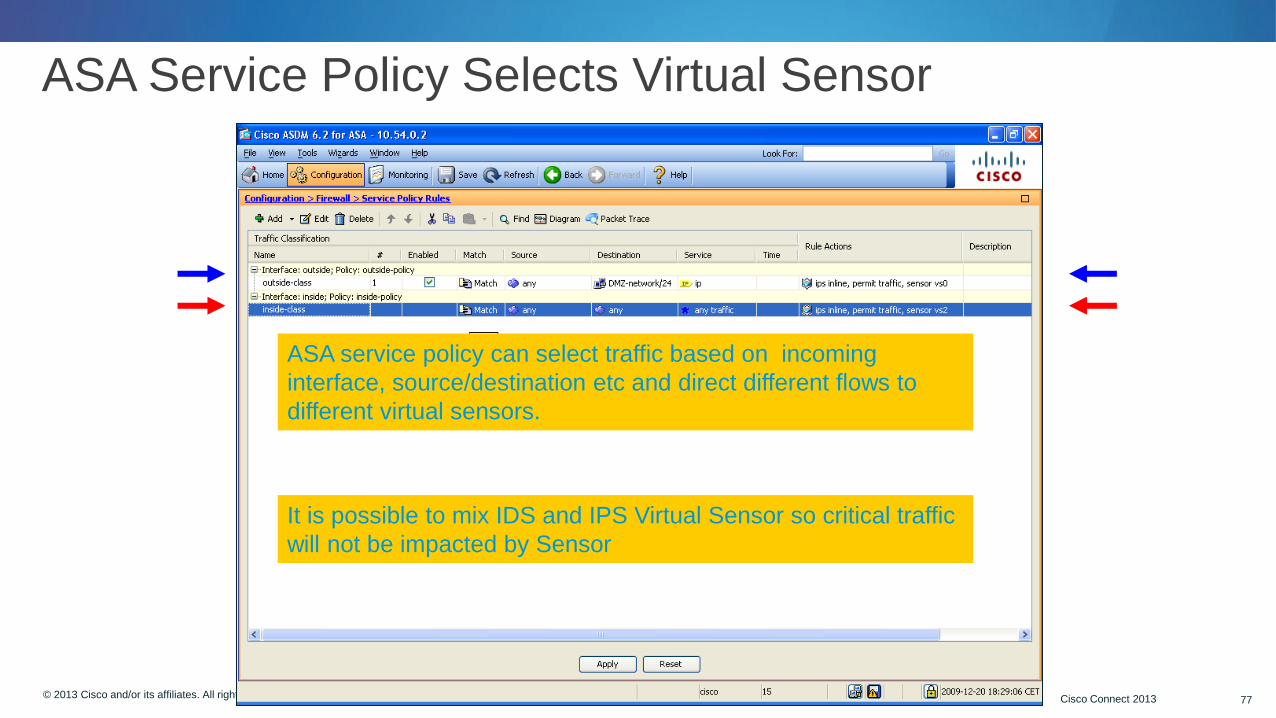
ASA Service Policy Selects Virtual Sensor
ASA service policy can select traffic based on incoming
interface, source/destination etc and direct different flows to
different virtual sensors.
It is possible to mix IDS and IPS Virtual Sensor so critical traffic
will not be impacted by Sensor

© 2012 Cisco and/or its affiliates. All rights reserved. Cisco Connect 78 © 2013 Cisco and/or its affiliates. All rights reserved. Cisco Connect 2013 78 Data Center Security
Multi-Sensor Environment with Cisco Security Manager 4.4
• Add all sensors into CSM
• Cleared a shared Policy and Policy Bundle
• Assign the Policy Bundle to all cluster members
• Tune the Policy Bundle
• “Submit and Deploy” to apply tuned configuration to all members
• Deep technical overview here: http://www.cisco.com/web/learning/le21/le39/docs/tdw_167_prezo.pdf