data center hyper-scale fabrics: scale-out architecture...
TRANSCRIPT

DATA CENTER
Hyper-Scale Fabrics: Scale-out Architecture with Brocade DCX 8510
Brocade® offers second-generation 64 Gbps Optical Inter-Chassis Link (ICL) connectivity that is unique to the Brocade DCX 8510-4 and 8510-8 chassis. This feature provides a unique way to connect multiple Brocade 8510 chassis together to help with enabling scale-out network design without using line card ports.

DATA CENTER FEATURE BRIEF
Hyper-Scale Fabrics: Scale-out Architecture with Brocade DCX 8510 2 of 11
CONTENTS Contents................................................................................................................................................................................................................................................2 Introduction..........................................................................................................................................................................................................................................3 Hyper-scale fabrics ............................................................................................................................................................................................................................4
ICL Licensing ....................................................................................................................................................................4 Supported Topologies ......................................................................................................................................................................................................................5
Core/Edge Topology ........................................................................................................................................................5 Mesh Topology .................................................................................................................................................................6
QSFP ICL Overview............................................................................................................................................................................................................................6 QSFP Trunking Between Chassis.................................................................................................................................................................................................8 QSFP Trunking Layout......................................................................................................................................................................................................................9 Use Case Scenarios........................................................................................................................................................................................................................10
Edge Application Engine............................................................................................................................................... 10 Fabric Consolidation with High-Density Modular Platforms....................................................................................... 10 FICON............................................................................................................................................................................. 10
Summary...........................................................................................................................................................................................................................................10
DATA CENTER FEATURE BRIEF
Hyper-Scale Fabrics: Scale-out Architecture with Brocade DCX 8510 3 of 11
INTRODUCTION As customers look to Fibre Channel (FC) storage area networks (SANs) for building private storage cloud services for their enterprise data centers, some of the key attributes are:
• Consolidated and highly virtualized pools of compute, storage and network resources
• Secure and efficient use of inter-fabric connectivity
• Lower capital and operational costs, higher asset utilization
• On-demand and efficient provisioning of application resources through automated management
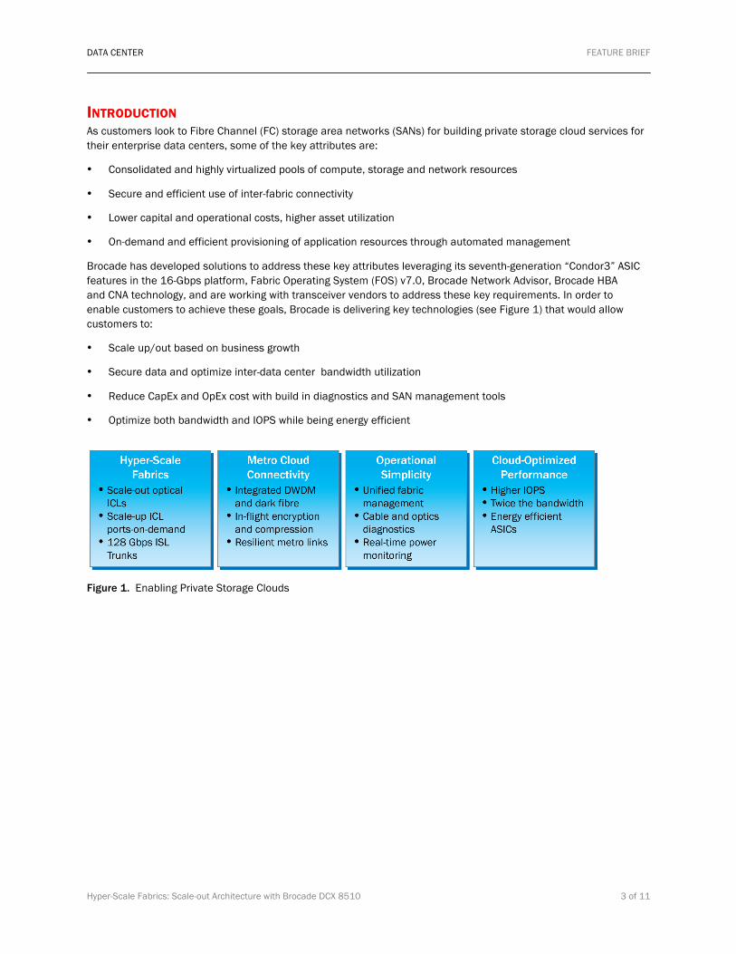
Brocade has developed solutions to address these key attributes leveraging its seventh-generation “Condor3” ASIC features in the 16-Gbps platform, Fabric Operating System (FOS) v7.0, Brocade Network Advisor, Brocade HBA and CNA technology, and are working with transceiver vendors to address these key requirements. In order to enable customers to achieve these goals, Brocade is delivering key technologies (see Figure 1) that would allow customers to:
• Scale up/out based on business growth
• Secure data and optimize inter-data center bandwidth utilization
• Reduce CapEx and OpEx cost with build in diagnostics and SAN management tools
• Optimize both bandwidth and IOPS while being energy efficient
Figure 1. Enabling Private Storage Clouds

DATA CENTER FEATURE BRIEF
Hyper-Scale Fabrics: Scale-out Architecture with Brocade DCX 8510 4 of 11
HYPER-SCALE FABRICS This is one of five technical briefs addressing Brocade solutions for helping customers in their transition to private storage clouds. Hyper-Scale Inter-Chassis Link (ICL) is a unique Brocade DCX 8510 feature that provides connectivity among two or more Brocade 8510-4 or 8510-8 chassis. This is the second generation of ICL technology from Brocade with optical QSFP (Quad Small Form Factor). The first generation used a copper connector. Each ICL connects the core routing blades of two 8510 chassis and provides up to 64 Gbps of throughput within a single cable. The Brocade 8510-8 allows up to 32 QSFP ports, and the 8510-4 allows up to 16 QSFP ports to help preserve switch ports for end devices.
With the new scale-out design, the complexity of trying to choose the right topology has changed. With Hyper-Scale ICLs you have the flexibility of a full mesh and multiple variations of core edge designs. Simplicity of use, while maintaining high availability, has never been easier.
This second generation of Brocade optical ICL technology—based on QSFP technology—provides a number of benefits to the customer. Brocade has improved ICL connectivity over the use of copper connectors by upgrading to an optical form factor. By doing this Brocade has also increased the distance of the connection from 2 meters to 50 meters. QSFP combines four cables into one cable per port. This significantly reduces the number of ISL cables the customer needs to run. Since the QSFP connections reside on the core blades within each 8510, they do not use up connections on the slot line cards. This frees up to 33% of the available ports for additional server and storage connectivity.
Each Brocade ICL Kit contains a single ICL license (1 Tbps of bandwidth) and 16 64-Gb QSFPs. The ICL kit differs from that of the previous generation; however, you can use the same kit for both the Brocade DCX 8510-8 and the DCX 8510-4 chassis. The 8510-8 chassis uses a maximum of two ICL kits, while the 8510-4 uses a maximum of one ICL kit.
ICL Licensing A ICL POD (Ports on Demand) license is applicable for both the Brocade 8510-8 and the 8510-4. The implementation of ICLs on the Brocade DCX 8510 platforms is significantly different from the ICL implementation on the DCX platforms:
• 8510-8
• 1 POD license on the 8510-8 provides the first half of QSFP ports (16). This is equivalent to 16 x 64 Gbps, or 1 TB of data.
• 2 POD licenses enable the remaining 16 QSFP ports. So, all 32 QSFP ports will be enabled across both core blades. This is equivalent to 32 x 64 Gbps, or 2 TB of data.
• 8510-4
• Only 1 POD license is required to enable all 16 QSFP ports. This is equivalent to 16 x 64 Gbps, or 1 TB of data.
NOTE: Although the ICL feature was introduced for the Brocade DCX Backbone with Fabric OS® (FOS) 6.0.x, the information in this document is based on FOS 7.0 or later. The QSFP information is also based on FOS 7.0 or later. The ICL POD kit has a different part number than earlier versions of the ICL kits.

DATA CENTER FEATURE BRIEF
Hyper-Scale Fabrics: Scale-out Architecture with Brocade DCX 8510 5 of 11
SUPPORTED TOPOLOGIES Prior releases of FOS 7.0 ICL topologies were limited to a maximum of 3 chassis and 2 meters in distance. With the Brocade 8510 core blades, which utilize QSFP technology, the supported topologies offer what is most needed by our customers. In the first release, Brocade will support up to 6 chassis within a fabric using only QSFP connections. The supported distance between the 8510 core blades is 50 meters.
NOTE: The topologies and scaling limits are based on what FOS 7.0 will support. This could change as FOS 7.0 is qualified within Brocade and its OEMs.
Core/Edge Topology Core/edge topology, also known as “CE,” is an evolution of the well-established “star” topology popularly used in data networks. CE designs have dominated SAN architecture for many reasons. CE topology is well tested, well balanced and economical.
The first release of the Brocade Hyper-Scale ICL feature targets up to six chassis that are connected using a CE design and QSFP technology. Figure 2 shows how a customer could choose two Brocade 8510s at the core and four on the edge.
Figure 2. Example of Core/Edge Topology

DATA CENTER FEATURE BRIEF
Hyper-Scale Fabrics: Scale-out Architecture with Brocade DCX 8510 6 of 11
Mesh Topology Mesh was a common design philosophy when SAN fabrics were first being built. Mesh designs were simple and easy to manage when using small switches, yet were seldom favored in director-class topology design. With the addition of QSFP ICL technology from Brocade, that has changed. As you build larger and larger fabrics, knowing where each storage and server port is located can become an operational nightmare. The Brocade ICL feature allows each Brocade 8510 to view every other 8510 in the fabric as a single hop. This drastically simplifies design and operational issues associated with deployment.
The first release of the Brocade Hyper-Scale ICL feature targets up to three chassis that are connected using a mesh design and QSFP technology. Figure 3 shows how a customer could choose three Brocade 8510s using a mesh design.
Figure 3. Example of Mesh Topology
QSFP ICL OVERVIEW As mentioned earlier, the second generation of Brocade ICL technology differs from the first generation in that it uses an optical connection rather than a copper connection. The distance that is supported by the connection has increased to 50 meters, instead of 2 meters.
Figure 4 shows a close-up of a QSFP cable and each optic connector. The QSFP cable has four links bundled together, each of which runs at a speed of 16 Gbps.
Figure 4. QSFP Optics

DATA CENTER FEATURE BRIEF
Hyper-Scale Fabrics: Scale-out Architecture with Brocade DCX 8510 7 of 11
To connect one Brocade 8510 to another, a minimum of four QSFP ports must be connected to the second chassis. This provides at least 256 Gbps of bandwidth between the 8510s. The dual connections must also reside within the same ICL trunk boundary on the core blades, as shown in Figure 5. The final layout is determined by the customer, depending on how many connections are needed between the 8510 chassis.
Figure 5. Minimum Connections Needed Between 8510 Chassis
NOTE: This setup utilizes QSFP trunking for the minimum connections. See the next section to learn more about QSFP trunking.

DATA CENTER FEATURE BRIEF
Hyper-Scale Fabrics: Scale-out Architecture with Brocade DCX 8510 8 of 11
QSFP TRUNKING BETWEEN CHASSIS Trunking involves taking multiple ISLs and forming one tunnel for traffic to transverse across. Brocade offers a number of hardware-based trunking solutions. The trunking process using QSFP ports varies slightly from product to product. The next section describes the basic trunking features of the QSFP ports.
As mentioned above, each QSFP port actually has four independent 16-Gbps links, each of which terminates on a different ASIC within the core blade. Each core blade has four ASICs. Figure 6 shows that each core blade has groups of four ports called trunking boundary cages. Each boundary cage has four QSFP ports that communicate back to the Condor 3 ASICs on each core.
Figure 6. Core Blade Trunking Boundary Cages
NOTE: A trunk cannot be formed within the same QSFP port.

DATA CENTER FEATURE BRIEF
Hyper-Scale Fabrics: Scale-out Architecture with Brocade DCX 8510 9 of 11
QSFP TRUNKING LAYOUT Figure 7 shows a minimum trunking connection setup between two Brocade 8510 chassis. Since the two red lines fall within the same trunk boundary, they form four trunks with two ports. Each trunk group has 32 Gbps of bandwidth. All four connections will carry traffic across the ISL links.
Figure 7. QSFP two director Trunking
NOTE: This is a hypothetical example to show which connections are trunked. A customer’s final layout will depend on their environment.
Figure 8. QSFP Three-Director Trunking
DATA CENTER FEATURE BRIEF
Hyper-Scale Fabrics: Scale-out Architecture with Brocade DCX 8510 10 of 11
NOTE: Just as in Figure 6, four trunk groups are created within each QSFP connection, shown between the directors (represented by the red, purple and green lines): • Domain 1 and Domain 2
• Domain 1 and Domain 3
• Domain 2 and Domain 3
Each trunk group has two 16-Gbps links, which form four 32-Gbps trunks.
USE CASE SCENARIOS There are a number of scenarios for which the use of ICL connectivity is a good choice:
• An edge application engine
• Fabric consolidation
• Fiber connectivity (FICON) environment (dual-chassis configuration only)
Edge Application Engine When customers prefer to install application engines (encryption, data migration, Fibre Channel Routing on the edge, the Brocade 8510-4 can be used as an “application engine,” housing up to four encryption and application blades. The Brocade 8510-8 can be used for switching, since routing is insulated from the need for application restarts, which occur on the Brocade 8510-4. This solution provides up to 1024 Gbps of aggregate ICL bandwidth, based on the total ICL bandwidth on the Brocade 8510-4.
Fabric Consolidation with High-Density Modular Platforms The majority of Storage Area Networks (SANs) have fewer than 1,000 ports in any single fabric. ICL connectivity provides the option of building a SAN with 3 x Brocade 8510s instead of a traditional core-edge architecture with switches and directors. A triangular mesh or CE topology provides up to 1,536 ports with 16 x 64 Gbps or 1024 Gbps connectivity between any Brocade 8510 pair. In addition, this architecture contains fewer domains to manage, easier firmware upgrades, and fewer disruptions. In this and other scenarios, customers can save the front-end ports for device connectivity—eliminating the need to purchase additional port blades for device connectivity.
FICON Dual-chassis backbone topologies connected through low-latency ICL connections are ideal in a FICON environment. The majority of FICON installations have switches that are connected in dual or triangular topologies, using ISLs to meet the FICON requirement for low latency between switches.
SUMMARY New 64Gbps QSFP based ICLs enable simpler, flatter, low-latency chassis topologies spanning up to 50 meter distance with off the shelf cables. They reduce inter-switch cables by 75% and preserve 33% of front end ports for servers and storages leading to fewer cables and more usable ports in a smaller foot print.
To find out more about the Brocade 8510 family and ICL features and benefits, talk to your sales representative or visit http://www.brocade.com/products-solutions/products/dcx-backbone/index.page.

DATA CENTER FEATURE BRIEF
Hyper-Scale Fabrics: Scale-out Architecture with Brocade DCX 8510 11 of 11
© 2011 Brocade Communications Systems, Inc. All Rights Reserved. 04/11 GA-FB-373-00
Brocade, the B-wing symbol, BigIron, DCFM, DCX, Fabric OS, FastIron, IronView, NetIron, SAN Health, ServerIron, TurboIron,and Wingspan are registered trademarks, and Brocade Assurance, Brocade NET Health, Brocade One, Extraordinary Networks, MyBrocade, VCS, and VDX are trademarks of Brocade Communications Systems, Inc., in the United States and/or in other countries. Other brands, products, or service names mentioned are or may be trademarks or service marks of their respective owners.
Notice: This document is for informational purposes only and does not set forth any warranty, expressed or implied, concerning any equipment, equipment feature, or service offered or to be offered by Brocade. Brocade reserves the right to make changes to this document at any time, without notice, and assumes no responsibility for its use. This informational document describes features that may not be currently available. Contact a Brocade sales office for information on feature and product availability. Export of technical data contained in this document may require an export license from the United States government.