data card system - onboard systems
TRANSCRIPT

Data Card System
Owner's Manual
C-20 Data Recorder
C-22 Data Card
C-23 Printer
C-24 Data Card Reader
13915 NW 3rd Court Vancouver Washington 98685 USA Phone: 360-546-3072 Fax: 360-546-3073 Toll Free: 800-275-0883
www.OnboardSystems.com

Copyright © 1992 by Onboard Systems, Inc. Printed in the United States of America.
All rights reserved. No part of this publication may be reproduced, stored in a retrieval
system, or transmitted, in any form or by any means, electronic, mechanical,
photocopying, recording, or otherwise, without prior written permission of Onboard
Systems, Inc., 13915 NW 3rd Court Vancouver Washington 98685 USA.
Phone: 360-546-3072 Fax: 360-546-3073 Toll Free: 800-275-0883.
www.OnboardSystems.com
The information contained in this manual is offered as is, without warranty of any kind,
express or implied. ONBOARD SYSTEMS DISCLAIMS SPECIFICALLY THE
IMPLIED WARRANTIES OF MERCHANTABILITY AND FITNESS FOR A
PARTICULAR PURPOSE. In no event shall Onboard Systems be liable for indirect,
special, incidental or consequential damages resulting from the use of the information,
even if Onboard Systems has been advised of the possibility of such damages.
If acquired subject to FAR or DFARS, the following shall apply as applicable:
Unpublished — rights reserved under the copyright laws of the United States.
RESTRICTED RIGHTS LEGEND
Use, duplication, or disclosure by the Government is subject to restrictions as set forth
in subparagraph (c) (1) (ii) of the Rights in Technical Data and Computer Software
clause at DFARS 52.227-7013. of Onboard Systems, Inc., 13915 NW 3rd Court
Vancouver Washington 98685 USA.
IBM is a registered trademark of International Business Machines
First printing May 1992
Document number 120-024-02
Revision 5, October 26, 2007

RECORD OF REVISIONS
Revision
Date
Page(s)
Reason for Revision
3 6-29-00 3-11
3-12
3-14
4-3
5-1
6-1
7-2
Changed minimum lift load to average load time.
Removed reference to manual mode setting.
Added reference to manual mode setting.
Defined battery change time.
Added note.
Added note.
Added Initializing troubleshooting.
4 07/19/02 All Manuals Address Change
5 10/29/07 All Added explanation of warnings, cautions and notes to
section 1. Updated warnings, cautions and notes
through out. Deleted references to Apple/ Macintosh
software. Updated page number format. Deleted
index.
Register Your Products for Automatic Notifications
Onboard Systems offers a free notification service via fax or email for product alerts and
documentation updates. By registering your Onboard Systems products at our website, we will
be able to contact you if a service bulletin is issued, or if the documentation is updated.
You can choose to receive notices on an immediate, weekly, or monthly schedule via fax, email
or both methods. There is no charge for this service. Please visit our website at
www.onboardsystems.com/notify.php to get started.

This page intentionally left blank.

i
Contents
Section 1 Introduction Warnings, Cautions and Notes, 1-1
System Overview, 1-2
Bill of Materials, 1-4
Components, 1-5
C-20 Data Recorder, 1-5
C-23 Printer, 1-6
C-22 Data Card, 1-7
C-24 Data Card Reader, 1-8
Software, 1-8
Section 2 Installing the Data Card System Unpacking Inspection, 2-1
Installing the Data Recorder, 2-2
Installing User-Supplied Switches, 2-2
Installing the Flight-Time Switch, 2-3
Installing a Capture Switch, 2-4
Making Electrical Connections, 2-5
Installing the Data Card Reader, 2-5
To a Printer, 2-5
To a Personal Computer, 2-6
Installing the Optional Software, 2-6
IBM PC and Compatibles, 2-6
Section 3 Operating the Data Recorder and Printer About the Front Panel, 3-2
Turning on the Data Recorder, 3-3
Setting the Display, 3-3
Adjusting the Back-Lighting, 3-3
Adjusting the Display Contrast, 3-4
Using the Menus, 3-5
Accessing Menus with the System Menu, 3-6
Scrolling Through a Menu, 3-7
Changing a Menu Selection, 3-7
Exiting a Menu, 3-7
ii
Section 3, cont. Operating the Data Recorder and Printer Entering Setup Data, 3-8
Entering Pilot Identifier, 3-10
Entering Aircraft Identifier, 3-11
Setting Recording Mode, 3-12
Setting Minimum Lift Load, 3-13
Setting Minimum Lift Time, 3-14
Setting the Average Time, 3-15
Entering the Date, 3-16
Entering the Time, 3-17
Specifying Flight-Time Switch Polarity, 3-18
Setting the Units Legend, 3-19
Managing the Customer List, 3-20
Managing the Location List, 3-22
Entering Company Data, 3-24
Using the Utilities Menu, 3-26
Viewing the Software Version Number, 3-27
Viewing the Data Recorder Battery Level, 3-27
Viewing the Data Card Status, 3-28
Erasing the Data Card, 3-29
Using the Run Screen, 3-30
During a Lift, 3-30
During a Flight, 3-31
Viewing Customer Totals, 3-32
Recording a Lift, 3-33
Using the Optional Printer, 3-36
Turning on the Printer, 3-36
Printing a Self-Test, 3-36
Installing the Paper, 3-36
Installing the Cartridge Ribbon, 3-37
Clearing a Paper Jam, 3-38
Printing a Report, 3-39
Reading a Report, 3-40
Changing the Data Recorder Battery, 3-43
Attention Messages, 3-45
System Conditions, 3-45
Card Status Messages, 3-46

iii
Section 4 Using the Data Card Inserting the Data Card, 4-2
Setting the Write-Protect Switch, 4-3
Replacing the Data Card Battery, 4-3
Erasing the Data Card, 4-4
Memory Capacity of the Data Card, 4-5
Section 5 Operating the Data Card Reader Using a Serial or Parallel Printer, 5-1
Connecting the Printer, 5-1
Operating the Printer, 5-1
Using an IBM PC-Compatible Computer, 5-1
Connecting the Computer, 5-1
Reading the Printed Report, 5-2
Section 6 Using the Optional Software IBM PC-Compatible, 6-1
Loading the Software, 6-1
Main Menu F1: Display Card Data, 6-2
Display Card Data PgUp and PgDn, 6-3
Display Card Data F1: Customer, 6-3
Display Card Data F2: Location, 6-4
Display Card Data F4: Info, 6-4
Display Card Data F5: File, 6-5
Display Card Data F6: Prnt, 6-5
Main Menu F2: Clear Data Card, 6-5
Main Menu F3: Alter Report Head, 6-6
Main Menu F4: Enter Setup Data, 6-7
Enter Setup Data F1: New Display Colors, 6-7
Enter Setup Data F2: Default Save Format, 6-7
Enter Setup Data F3: Default Directory, 6-8
Section 7 Maintaining the System Data Recorder Care, 7-1
Cable and Connector Maintenance, 7-1
Troubleshooting, 7-2

iv
Section 8 Installation Authorization FAA Letter of Authorization, 8-1
Appendix Specifications, A-2
Physical Specifications, A-2
Electrical Specifications, A-2
Ordering Information, A-4
Limited Warranty, A-5
Return Instructions, A-6
Figures 1-1 The data card system's aircraft-based components, 1-3
1-2 The data card system's office-based components, 1-4
1-3 C-20 Data Recorder, 1-5
1-4 C-23 Printer, 1-6
1-5 Data card, 1-7
1-6 Data card reader, 1-8
2-1 Installing the data recorder, 2-2
2-2 Flight-time switch wiring guide, 2-3
2-3 Capture switch wiring guide, 2-4
3-1 Data recorder front panel, 3-2
3-2 System Menu loop, 3-6
3-3 Setup Data menu loop, 3-9
3-4 Company Data menu loop, 3-25
3-5 Utilities menu loop, 3-26
3-6 Run screen with lift information, 3-30
3-7 Run screen with flight information, 3-31
3-8 Run screen with customer totals, 3-32
3-9 Recording a lift, 3-35
3-10 An example full report, 3-41
3-11 An example summary for Customer 1, 3-42
3-12 Data recorder battery, 3-44
4-1 Inserting the data card, 4-2
5-1 Typical customer report, 5-2

v
Tables 3-1 Reports types and their screen selections, 3-39
3-2 Sections printed on a report or a summary, 3-42
A-1 Physical specifications, A-2
A-2 Data recorder electrical specifications, A-2
A-3 Data Recorder Pin Out, A-2
A-4 C-39 Indicator Pin Out, A-3
A-5 Load Cell Pin Out, A-3
A-6 Ordering information, A-4

This page intentionally left blank.

General Information 1-1
Section 1
Introduction
This manual describes installation and operation of the ONBOARD
SYSTEMS Data Card System.
Please read the procedures and other information
given in this manual before attempting to install
or operate this system.
Warnings, Cautions & Notes
The following definitions apply to Warnings, Cautions & Notes used in
this manual.
Means that if this information is not observed,
serious injury, death or immediate loss of flight
safety could occur
Means that there is a risk of injury or
degradation in performance of equipment if this
information is not observed.
Draws the reader’s attention to information
which may not be directly related to safety, but
which is important or unusual.

1-2 General Information
System Overview
The ONBOARD SYSTEMS Data Card System is a hook-load data
recording accessory system designed to complement ONBOARD
SYSTEMS E Series hook-load measuring systems. The data card system
frees the pilot and ground personnel from the recording task by logging
the hook-load weight, date and time, and duration for each lift. Summary
totals and averages are also calculated. The recorded information can be
printed directly or transferred to your office printer or computer for
printing or further processing. The data card system is FAA-approved
for installation with E Series hook-load measuring systems.
The system integrates hook-load measurement with computerized data
recording. While the measuring system measures the weight of lifts
during a job, the data recorder displays flight and lift information, and
creates a comprehensive record of this data on the credit-card-sized data
card. A job report can be printed on the C-23 printer, or the data card
reader can be used to transfer the recorded information to your serial
printer, parallel printer, or personal computer for printing or further
processing. Optional user-interface software for IBM PC 100%-
compatible computers allows you to display, print, and save the
collected data as ASCII text. Future software will provide data
conversion to file formats compatible with a variety of accounting,
spreadsheet, data base, and word processing programs.
The data card system complements your existing weighing system,
providing an additional source of lift data that is rigorously collected
throughout the job. However, you should not rely on the accuracy of the
data unless you are confident that the system is correctly installed and
that the pilot is using the system correctly.
A complete data card system includes a data recorder, one or more data
cards, a data card reader, and, optionally, software for your computer. A
single data card reader can support many data card systems installed in
separate aircraft.
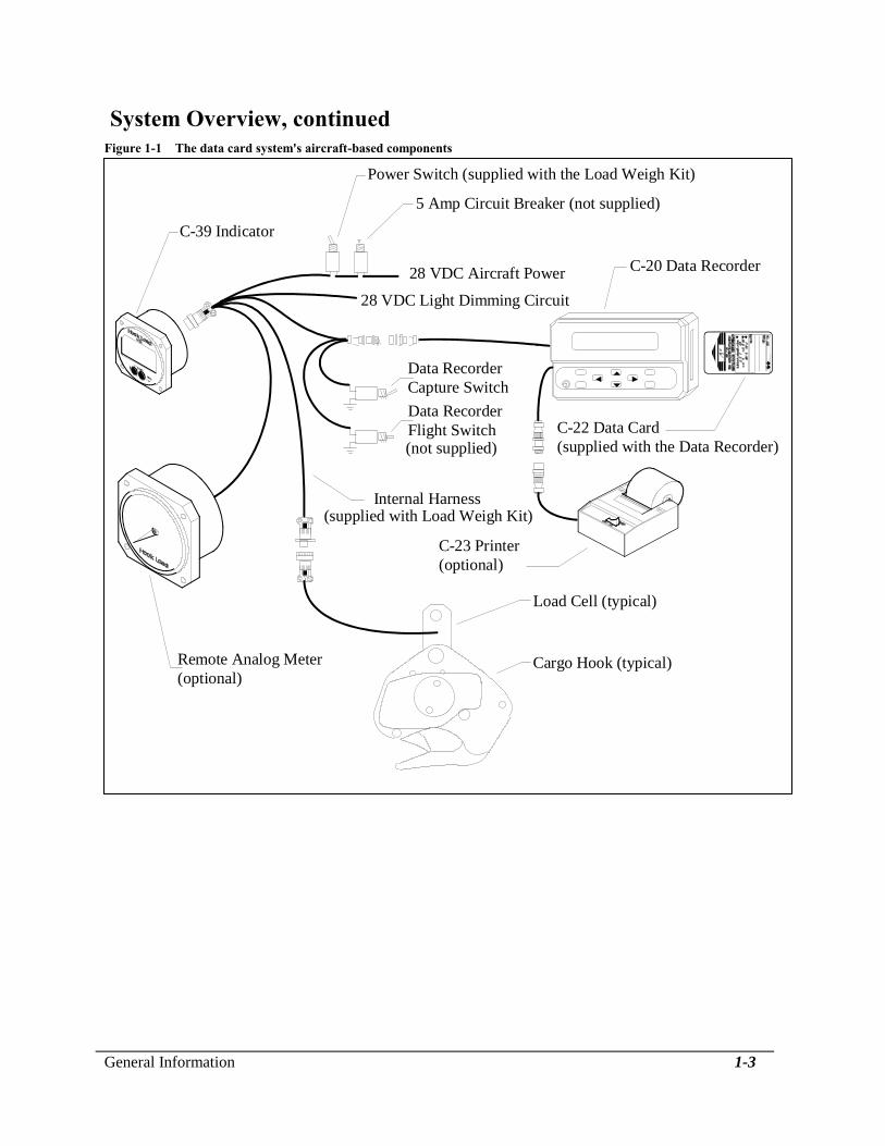
Figure 1-1 shows the data card system components that are installed in
the aircraft. Figure 1-2 shows the components that are installed in the
office. The data card is the link between the two environments. It carries
data collected by the data recorder to the data card reader, where it can
be read or printed.
General Information 1-3
System Overview, continued
Figure 1-1 The data card system's aircraft-based components
28 VDC Aircraft Power
Internal Harness
C-20 Data Recorder
Data Recorder
Capture Switch
Cargo Hook (typical)
Data Recorder
Flight Switch
C-39 Indicator
Remote Analog Meter
(optional)
Load Cell (typical)
C-23 Printer
(optional)
28 VDC Light Dimming Circuit
C-22 Data Card
(supplied with the Data Recorder)
Power Switch (supplied with the Load Weigh Kit)
5 Amp Circuit Breaker (not supplied)
(supplied with Load Weigh Kit)
(not supplied)

1-4 General Information
System Overview, continued
Figure 1-2 The data card system's office-based components
Your personal computerand/or printer
Data card
Data card reader
AC adaptor
Bill of Materials
The following items are included with each system, if shortages are
found contact the distributor from whom the system was purchased.
P/N DESCRIPTION QUANTITY
120-024-02 Owner's Manual 1
210-048-01 C-20 Data Recorder 1
210-100-00 C-23 Data Printer 1*
475-006-00 C-22 Data Card 1
270-019-00 Capture Switch Wire 1
270-022-00 Flight Time Switch Wire 1
235-051-00 Mounting Bracket 1
511-005-00 Knurled Mounting Screw 2
* Optional

General Information 1-5
Components
The following paragraphs describe the major components of the data
card system in greater detail. These components are the C-20 Data
Recorder, the C-23 Printer, the C-22 Data Card, the C-24 Data Card
Reader, and the optional interface software.
C-20 Data Recorder The C-20 Data Recorder is a programmable microprocessor-based
device that attaches to an existing connector on the E Series hook-load
measuring system in the cockpit. It reads data entered by the pilot and
monitors the data from the weighing system. A two-line by 20-character
alphanumeric LCD display shows duration information for the current
flight, and duration and weight data for the current load in pounds or
kilograms. Eight front panel keys let the pilot enter identifying
information and change display characteristics. All data is recorded on
a data card that plugs into the data recorder. The display shows current
flight and lift data and can be used as a copilot remote indicator.
Several aircraft can share a single data recorder without extensive
reinstallation. Figure 1-3 shows the C-20 Data Recorder.
Figure 1-3 C-20 Data Recorder
Display
Power switch
Data card slot
Mounting Bracket
Keyboard

1-6 General Information
C-23 Printer The C-23 Printer is a compact, easy to use, 24-characters per line
printer. It is connected directly to the data recorder, making it possible
to print reports in the aircraft. Figure 1-4 shows the C-23 Printer.
Figure 1-4 C-23 Printer
Paper Roll
Power ON
Indicator
Power Switch
Connector
(connects to C-20)

General Information 1-7
C-22 Data Card The C-22 Data Card is a compact memory device that is the shape and
size of a credit card. It plugs into the data recorder during lift operations
where it records hook-load data such as weight of the load, and clock
data such as lift start time and duration. The card then transfers the data
to an office printer or an IBM-compatible or Macintosh computer via
the C-24 Data Card Reader.
When the data card is installed in the data recorder or data card reader,
it gets its power from that unit. When the data card is not in use, it is
powered by a battery located in one end of the card. A write-protect
switch is also available. The data card can be erased at any time using
the data recorder or the office computer and reused indefinitely. Two
data card memory capacities are available, 8 Kb (kilobytes) and 32 Kb.
The 8 Kb card stores 714 entries, and the 32 Kb card stores 2,574
entries. Figure 1-5 shows the data card. Refer to the section, Using the
Data Card, for more information about the data card.
Figure 1-5 Data card
Battery holder
Battery
Write-protect switch
Data card

1-8 General Information
C-24 Data Card Reader The C-24 Data Card Reader is a compact card reader and serial/parallel
interface that connects to a printer or an IBM-compatible or Macintosh
computer. To retrieve lift data from the C-22 Data Card, you plug the
card into the data card reader. When connected to a printer, the data
card reader automatically prints a complete job report including your
company data, aircraft and pilot identifiers, customer and location
identifiers, number of lifts, time and duration of each lift, weight, and a
summary section of totals and averages. When the data card reader is
connected to a computer, you use menus to display, print, and save the
report information. Figure 1-6 shows the data card reader.
Software Optional user-interface software for your IBM PC-compatible
computer prompts the user to display, print, and save the collected data.
Figure 1-6 Data card reader
Serial Connector
ParallelConnector
Back viewFront view
Towalloutlet
Powerlight
Powerswitch
Cardslot
AC adaptor

Installing the Data Card System 2-1
Section 2
Installing the Data Card System
This section describes how to install the components of the Data Card
System.
Unpacking Inspection
After unpacking the components of your data card system, check each
component against the packing list to ensure that you have received the
correct configuration. If you find an error, notify the distributor
immediately.
Inspect the components for evidence of mishandling or damage. All parts
packaged at the factory were carefully tested, inspected, and packed. If
damage is evident, do not proceed with installation. Instead, file a claim
with the carrier and notify the distributor from whom the components
were purchased. Refer to the Appendix for more information about
returning a system component.
Installing the Data Recorder
The data recorder can be installed either permanently or temporarily.
With temporary installation you can easily transfer the data recorder
between several aircraft.
When the optional C-23 printer is used, the circuit
breaker must be rated at 5 amp.

2-2 Installing the Data Card System
Installing the Data Recorder, contiuned
Follow these steps to install the data recorder in the aircraft cockpit.
Refer to Figure 2-1, and to Figure 1-1 earlier in this manual.
1. Select an installation location within easy reach of the pilot that
allows comfortable viewing during flight. For temporary installation,
the data recorder can be secured with a seat belt. Ensure that there is
sufficient clearance to insert a data card in the card slot on the right
side of the data recorder.
2. Secure the mounting bracket in the selected location.
3. Attach the data recorder to the mounting bracket with the two thumb
screws provided.
4. The data recorder has two connectors. The connectors are configured
differently to prevent mismatching them. Connect one to the load
weigh system's internal harness and the other to the C-23 Printer.
Refer to Figure 1-1 earlier in this manual.
Figure 2-1 Installing the data recorder
4"
Allow clearancefor data card
Thumb screw
Grommet
Mounting bracketMounting holes
Installing User-Supplied Switches
The flight-time and load-capture switches give the pilot direct control
over the timing of flight and load measurements. The switches are
supplied by the user.

Installing the Data Card System 2-3
Installing the
Flight-Time Switch
Installation of the flight-time switch is required. The switch allows the
data recorder to register the beginning and end of each flight. You can
install the flight-time switch at any available switch, either normally
open or normally closed, on the helicopter controls or in another
location that is convenient to the pilot. For a typical installation you
would install the flight-time switch on the collective so that when the
pilot pulls up on the collective, the switch opens (or closes) and flight
time begins counting. A six-foot length of red-coated 24-gauge wire is
supplied for use in installing the flight-time switch. The wire is
equipped with a pin connector on one end.
The flight-time switch can be wired several ways. Use this procedure
and Figure 2-2 as a guide. Refer back to Figure 1-1 for an overview
diagram of the switch location in the system.
1. Disassemble the data recorder connector located in the load weigh
internal harness by unscrewing it. Notice that each pin socket is
labeled with a number.
2. Insert the pin connector of the supplied wire into Pin Socket #4.
Be sure the pin socket is the correct one. Once
inserted, the pin cannot be removed without the
use of a special tool.
3. Reassemble the data recorder connector.
4. Cut the free end of the wire to the desired length.
5. Connect the wire to the selected switch.
6. Connect the other side of the switch to a good airframe ground.
7. Using the data recorder's Setup Data menu, set the flight switch menu
item to the appropriate polarity setting based on flight-time switch
wiring: Select HIGH if the data recorder is connected to airframe
ground during flight, select LOW if the data recorder is disconnected
from airframe ground during flight.
Figure 2-2 Flight-time switch wiring guide
Data
Airframe Ground Switch Recorder
(normally open or normally closed)

2-4 Installing the Data Card System
Installing a Capture
Switch
A capture switch gives the data recorder the capability of registering the
weight of a load at the moment the pilot presses the switch. A capture
switch is not required; the data recorder automatically takes load
readings throughout each lift, discards outlying values, and records an
average weight for the lift. Lifts measured automatically and lifts
captured with a capture switch can be intermingled. The display and the
printouts indicate which load measurements are captured.
If a capture switch is desired, you can use any available normally open
switch on the helicopter controls or any other normally open switch. The
switch location should be convenient for the pilot to use. A six-foot
length of purple-coated 24-gauge wire is supplied for use in installing a
capture switch. The wire is equipped with a pin connector on one end.
To install the capture switch, use this procedure and Figure 2-3 as a
guide. Refer back to Figure 1-1 for an overview diagram of the switch
location in the system.
1. Disassemble the data recorder connector located in the load weigh
internal harness by unscrewing it. Notice that each pin socket is
labeled with a number.
2. Insert the pin connector of the supplied wire into Pin Socket #2.
Be sure the pin socket is the correct one. Once
inserted, the pin cannot be removed without the
use of a special tool.
3. Reassemble the data recorder connector.
4. Cut the free end of the wire to the desired length.
5. Connect the wire to the selected switch.
6. Connect the other side of the switch to a good aircraft ground source.
Figure 2-3 Capture switch wiring guide
Data
Airframe Ground Switch Recorder
(normally open)

Installing the Data Card System 2-5
Making Electrical Connections
To connect the data recorder, plug the connector on the data recorder
into the socket provided on the internal harness of the load weighing
system. Refer back to Figure 1-1 for an overview diagram.
Installing the Data Card Reader
The data card reader can either be connected to a standard office serial
or parallel printer or to a personal computer for further processing. If
connected directly to a printer, all the information from the data card
will be printed. If the card reader is connected to a personal computer
and the optional software is used you will be able to display, print, or
save the collected data as ASCII text.
To a Printer
Follow this procedure to install the C-24 Data Card Reader directly to a
printer. Refer back to Figure 1-2 for an overview diagram.
To install the data card reader, you need to obtain
an appropriate printer cable. The card reader is
fitted with two connectors. The 9-pin is the serial
port and the 25-pin is the parallel port. Obtain
the appropriate cable to connect the card reader
port to your printer. Due to the number of cable
and connector combinations, a cable is not
supplied with the card reader. If you are
connecting the card reader to a serial printer do
not use a Null Modem cable.
1. Ensure that the power to your printer is off.
2. Connect the printer cable between the data card reader and your
printer.
3. Plug the AC adaptor cable into the small round receptacle on the side
of the data card reader.
4. Plug the AC adaptor into a wall outlet.
5. Turn on your printer and put it on-line.
6. Turn on the card reader.
7. To print a report, insert the data card to be read gently but firmly into
the card slot on the front of the data card reader. The report begins
printing. Figure 5-1 shows an example.
2-6 Installing the Data Card System
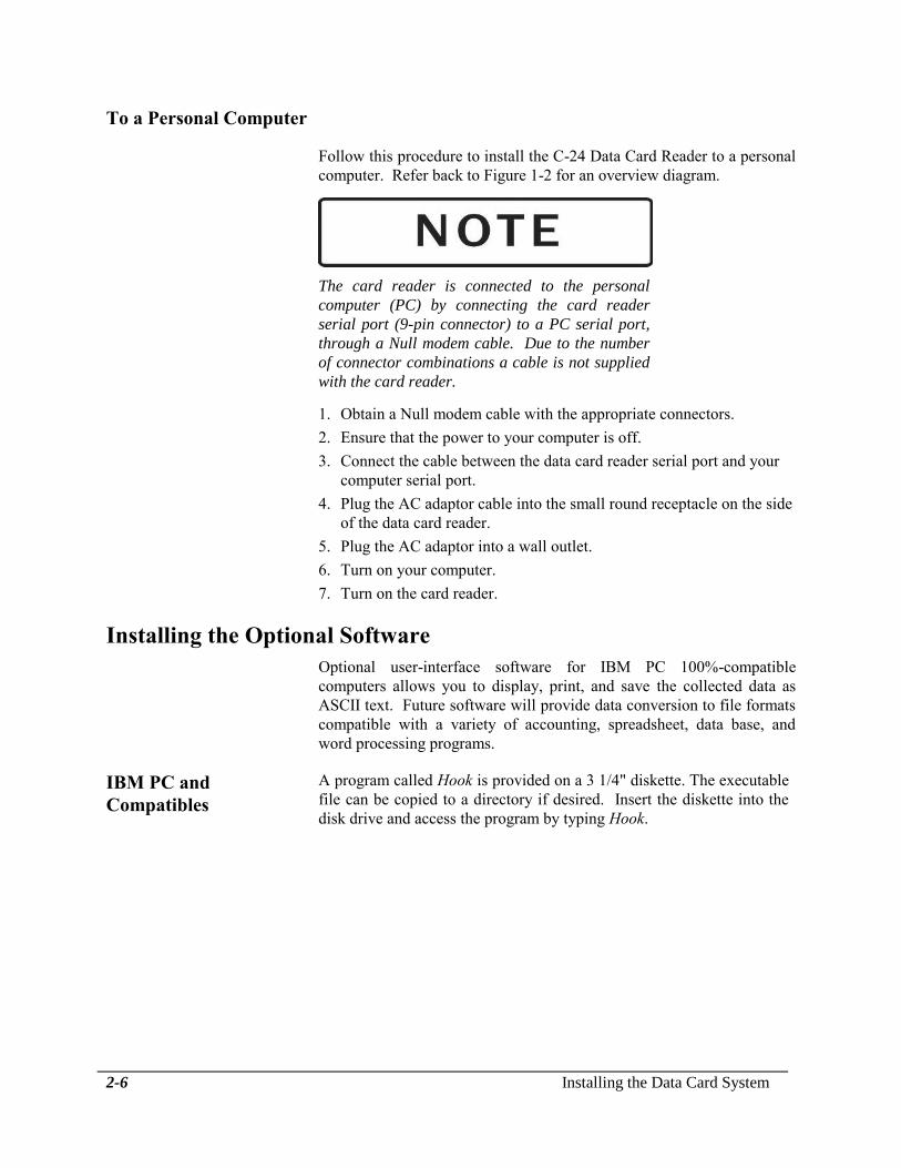
To a Personal Computer
Follow this procedure to install the C-24 Data Card Reader to a personal
computer. Refer back to Figure 1-2 for an overview diagram.
The card reader is connected to the personal
computer (PC) by connecting the card reader
serial port (9-pin connector) to a PC serial port,
through a Null modem cable. Due to the number
of connector combinations a cable is not supplied
with the card reader.
1. Obtain a Null modem cable with the appropriate connectors.
2. Ensure that the power to your computer is off.
3. Connect the cable between the data card reader serial port and your
computer serial port.
4. Plug the AC adaptor cable into the small round receptacle on the side
of the data card reader.
5. Plug the AC adaptor into a wall outlet.
6. Turn on your computer.
7. Turn on the card reader.
Installing the Optional Software
Optional user-interface software for IBM PC 100%-compatible
computers allows you to display, print, and save the collected data as
ASCII text. Future software will provide data conversion to file formats
compatible with a variety of accounting, spreadsheet, data base, and
word processing programs.
IBM PC and
Compatibles
A program called Hook is provided on a 3 1/4" diskette. The executable
file can be copied to a directory if desired. Insert the diskette into the
disk drive and access the program by typing Hook.

Operating the Data Recorder and Printer 3-1
Section 3
Operating the Data Recorder and Printer
This section describes operation of the C-20 Data Recorder and C-23
Printer. Here are the topics in this section.
About the Front Panel describes the keys, switches, and display of
the front panel.
Turning on the Data Recorder describes how to power up the data
recorder.
Setting the Display describes how to set the display contrast and
back-lighting to accommodate current lighting conditions and the
position of the data recorder.
Using the Menus describes the System Menu and gives general
procedures for operating and accessing its submenus.
Entering Setup Data gives detailed procedures and information about
the values that can be entered using the Setup Data menu.
Entering Company Data describes the procedure for entering
information on the Company Data menu for inclusion in a report
header.
Managing the Customer List describes the procedure for entering up
to 10 different customers on the Manage Customer List menu.
Managing the Location List describes the procedure for entering up
to 10 different locations on the Manage Location List menu.
Using the Utilities Menu describes the screens and procedures
available using the Utilities menu.
Using the Run Screen shows the primary screen used during flight
operations and describes its displays.
Printing a Report gives detailed procedures and information about
using the optional printer and the Print menu.
Attention Messages describes messages that can appear on the front
panel display under certain conditions which require pilot attention.

3-2 Operating the Data Recorder and Printer
About the Front Panel
The front panel of the data recorder includes the following features, as
shown in Figure 3-1.
The power switch turns on the data recorder power.
The 2-line by 20-character liquid crystal display (LCD) shows lift
data, menu settings, and other information of interest to the pilot.
The ENTER key is used to enter new information, select menu
choices, and change menu settings.
The RESET key is used to reset data settings.
The LIGHT key is used to set the display back-lighting level.
The CONTR key is used to set the display contrast level.
The Up, Down, Left, and Right arrow keys are used to scroll through
the menus and change menu settings.
Figure 3-1 Data recorder front panel
Data card
slot
LIGHT (Back-light) key
Display
RESET key
ENTER key
Power switch
Arrow keys
CONTR(Contrast)key

Operating the Data Recorder and Printer 3-3
Turning on the Data Recorder
To turn on the data recorder, press the front panel power switch up.
When you turn on the data recorder, a screen similar to the following
appears on the display. If, instead, a message appears, refer to Attention
Messages for more information.
Load: 0 Lbs
Flight:000 00:00:00
The load weigh system must also be powered up
because the data recorder and printer power
comes through that system. Do not turn on the
data recorder or printer until the load weigh
system is powered up.
Setting the Display
Depending on ambient light conditions and the position of the data
recorder, you may want to change the back-lighting or contrast of the
front panel display. The following paragraphs describe these display
features and how to change them.
Adjusting the
Back-Lighting
The data recorder display includes an electroluminescent back-lighting
feature. Back-lighting helps compensate for different ambient lighting
conditions.
To change the intensity of the back-lighting, follow these steps.
1. While holding down the LIGHT key on the front panel, press and
hold the Up or Down key to step through the contrast levels. Pressing
the Up key increases the back-light level; pressing the Down key
decreases the back-light level.
2. Release the LIGHT key. The data recorder retains this setting until it
is changed.
3-4 perating the Data Recorder and Printer
Adjusting the
Display Contrast
The data recorder display is equipped with adjustable contrast control.
Setting the contrast adjusts the display to help compensate for different
viewing angles.
To change the contrast setting, follow these steps.
1. While holding down the CONTR key on the front panel, press the Up
and Down keys to step through the contrast levels. Pressing the Up
key decreases the contrast; pressing the Down key increases the
contrast.
2. Release the CONTR key. The data recorder retains this setting until it
is changed.

Operating the Data Recorder and Printer 3-5
Using the Menus
The software functions of the data recorder are grouped into menus that
you use to enter and display information.
The System Menu accesses the Setup Data, Customer List, Location
List, Company Data, and Utilities menus. Once you enter information
in these menus, it is retained until you change it.
The Setup Data menu contains job identification and setup data that
are determined by the pilot on-site. Once set, most of the entries,
such as date, time, pilot and aircraft rarely need to be reset.
The Manage Customer List menu allows you to enter up to ten
different customer names. Different information can be recorded for
each customer
The Manage Location List menu allows you to enter up to ten
different locations. Different information can be recorded for each
customer.
The Company Data menu provides six 20-character lines for the
entry of your company name and address or other information you
want printed as a report header.
The Utilities menu displays the system version number and remaining
data card storage, and allows you to erase a data card.
The Print menu is accessed by pressing ENTER when the Run screen
is displayed. The menu allows you to specify full report or summary
format, and to select a particular customer for the report.
The selections that appear on these menus are described in detail later in
this section.
The following paragraphs describe in general terms how to:
Use the System Menu to access the Setup Data menu, Customer List
Menu, Location List Menu, Company Data menu, and Utilities menu.
Scroll through a menu
Change the value of a menu setting
Exit a menu and return to the Run screen
For detailed information on a particular menu setting, refer to the
description of that setting later in this section.

3-6 Operating the Data Recorder and Printer
Accessing Menus with
the System Menu
You use the System Menu to access the Setup Data, Customer List,
Location List, Company Data, and Utilities menus. You can access the
System Menu whenever the Run screen is displayed. To access a menu,
follow these steps.
1. Press the Up and Down keys simultaneously to enter the System
Menu.
2. Use the Up and Down keys to select the desired menu name.
Figure 3-2 shows the screens on the System Menu.
3. Press ENTER to access the selected menu.
Figure 3-2 System Menu loop
System Menu
Enter Setup Data
System Menu
Manage Customer List
System Menu
Manage Location List
System Menu
Enter Company Data
System Menu
Utilities
Go to Run

Operating the Data Recorder and Printer 3-7
Scrolling Through a
Menu
To scroll through the selections on a menu without changing any
settings, press either the Up key or the Down key. The selections on
each menu are arranged in a continuous loop.
Changing a Menu
Selection
To change the current setting of a particular menu selection, follow
these steps.
1. Access the desired menu.
2. Use the Up and Down keys to scroll through the menu until you see
the desired selection.
3. Press the Right or Left key to access entry mode for the menu
selection. For alphanumeric and numeric entries, a cursor appears
below the first character that you can change.
4. Now enter the desired setting. Use the Left and Right keys to position
the cursor under the character, number, or setting you want to enter
or change. Then use the Up and Down keys to scroll through the
choices.
For alphanumeric entries such as aircraft identifier or company
data, the choices are the characters A-Z, 0-9, space, hyphen, slash,
apostrophe, and period.
For numeric entries such as date or time, the choices are 0-9.
For entries that are alternate choices, such as English and Metric,
you toggle between the choices.
Angle brackets are used to show the last choice entered.
5. When the setting is displayed correctly, press ENTER to enter the
new setting and return to the current menu. The menu selection that
follows the selection you just set is displayed.
Exiting a Menu To exit a menu and return to the Run screen, follow these steps.
1. Press the Up or Down key to scroll through the menu until the
following display appears.
Go to Run
2. Press the ENTER key. The Run screen appears.

3-8 Operating the Data Recorder and Printer
Entering Setup Data
The Setup Data menu allows you to view and enter setup data and job
information that are determined or verified by the pilot on-site. Some
values, such as aircraft and pilot identifiers, help identify the job. Some
entries, such as time and date, are used by the data recorder to calculate
data such as length of lift. Other settings, such as operating mode,
minimum lift load, minimum lift time, flight switch polarity, or units
setting, are determined by job conditions or the configuration of your
aircraft or weighing system.
Setup Data menu entries include these items.
Pilot identifier
Aircraft identifier
Operating mode, either automatic or manual recording
Minimum lift load, used during automatic recording
Minimum lift time, used during automatic recording
Average time
Current date
Current time
Flight switch polarity
Units legend, either LB or KG
Descriptions of each menu selection appear on the following pages.

Operating the Data Recorder and Printer 3-9
Entering Setup Data, continued
To access the Setup Data menu from the Run screen, follow these steps.
1. Press the Up and Down keys simultaneously to access the System
Menu.
2. Use the Up and Down keys to display the "Enter Setup Data"
selection.
System Menu
Enter Setup Data
3. Press ENTER. You can now scroll through the selections in the
Setup Data menu loop shown in Figure 3-3.
Figure 3-3 Setup Data menu loop
Setup Data
Pilot: R DEVOE
Setup Data
Date: 05/28/92
Setup Data
Aircraft:N12345678
Setup Data
Time: 13:42:58
Setup Data
Op Mode:<AUTO>
Setup Data
Flt switch:<High>
Setup Data
Min Lift Load:0400
Setup Data
Units:<LB>
Setup Data
Min lift time:015
Go To System Menu
Setup Data
Average time:00
Go To Run
3-10 Operating the Data Recorder and Printer
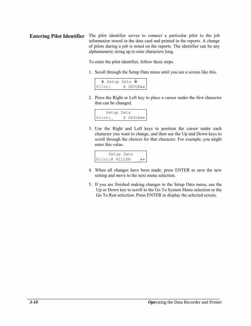
Entering Pilot Identifier The pilot identifier serves to connect a particular pilot to the job
information stored in the data card and printed in the reports. A change
of pilots during a job is noted on the reports. The identifier can be any
alphanumeric string up to nine characters long.
To enter the pilot identifier, follow these steps.
1. Scroll through the Setup Data menu until you see a screen like this.
Setup Data
Pilot: R DEVOE
2. Press the Right or Left key to place a cursor under the first character
that can be changed.
Setup Data
Pilot: R DEVOE
3. Use the Right and Left keys to position the cursor under each
character you want to change, and then use the Up and Down keys to
scroll through the choices for that character. For example, you might
enter this value.
Setup Data
Pilot:K HILLEN _
4. When all changes have been made, press ENTER to save the new
setting and move to the next menu selection.
5. If you are finished making changes in the Setup Data menu, use the
Up or Down key to scroll to the Go To System Menu selection or the
Go To Run selection. Press ENTER to display the selected screen.

Operating the Data Recorder and Printer 3-11
Entering Aircraft
Identifier
The aircraft identifier serves to connect a particular aircraft to the job
data stored in the data card and printed in the reports. Depending on
your need, the identifier might be the aircraft's tail number or serial
number, or any other alphanumeric string up to nine characters long.
To enter the aircraft identifier, follow these steps.
1. Scroll through the Setup Data menu until you see a screen like this.
Setup Data
Aircraft:N12345678
2. Press the Right or Left key to place a cursor under the first character
that can be changed.
Setup Data
Aircraft:N12345678
3. Use the Right and Left keys to position the cursor under each
character you want to change, and then use the Up and Down keys to
scroll through the choices for that character. For example, you might
enter this value.
Setup Data
Aircraft:N87654321
4. When all changes have been made, press ENTER to save the new
setting and move to the next menu selection.
5. If you are finished making changes in the Setup Data menu, use the
Up or Down key to scroll to the Go To System Menu selection or the
Go To Run selection. Press ENTER to display the selected screen.

3-12 Operating the Data Recorder and Printer
Setting Recording Mode The recording mode setting allows you to select between automatic and
manual recording modes. In automatic mode, the system automatically
records any lift that exceeds both the minimum load and minimum lift
time set. In manual mode, the system begins recording the lift only
when the pilot presses the capture switch.
If manual mode is set, the minimum lift time and average load time
information is not needed.
To set the system for automatic or manual recording, follow these steps.
1. Scroll through the Setup Data menu until you see an item like this.
Setup Data
Op Mode:<AUTO>
The angle brackets around the word "AUTO" indicate that in this
example the current setting is for automatic recording.
2. Press the Right or Left key to access the following screen.
Setup Data
Set Mode:MANUAL
3. Use the Right or Left key to toggle between the choices until the
desired selection is displayed.
4. Press ENTER to save the new setting and move to the next menu
selection.
5. If you are finished making changes in the Setup Data menu, use the
Up or Down key to scroll to the Go To System Menu selection or the
Go To Run selection. Press ENTER to display the selected screen.

Operating the Data Recorder and Printer 3-13
Setting Minimum
Lift Load
The minimum lift load setting allows you to specify the minimum
weight that determines a valid load. Defining a minimum load prevents
the system from recording every small load that is applied to the hook.
The minimum lift load setting can be any integer up to four digits long,
to a maximum of 9999. There is no scale in this function, entering 0400
means 400 LBs or KGs. The units legend (LB or KG) depends on the
units setting.
To change the minimum lift load, follow these steps.
1. Scroll through the Setup Data menu until you see an item like this.
Setup Data
Min Lift Load:0400
2. Press the Right or Left key to access the following screen. A cursor
appears under the first digit. The display also indicates the units
setting that is in effect.
Setup Data
Min Load (LB):0400
3. Use the Right and Left keys to position the cursor under each digit
you want to change, and then use the Up and Down keys to scroll
through the setting choices for that digit.
Setup Data
Min Load (LB):0250
4. When all changes have been made, press ENTER to save the new
setting and move to the next menu item.
5. If you are finished making changes in the Setup Data menu, use the
Up or Down key to scroll to the Go To System Menu selection or the
Go To Run selection. Press ENTER to display the selected screen.

3-14 Operating the Data Recorder and Printer
Setting Minimum
Lift Time
The minimum lift time setting allows you to specify the length of time
in seconds that a load must be carried to be recorded as a valid load.
Defining a minimum time prevents the system from recording a quick
tug on the hook as a valid load. The minimum lift time setting can be
any integer up to three digits long, to a maximum of 999 seconds.
If manual recording mode is set, this menu item does not appear.
To change the minimum lift time, follow these steps.
1. Scroll through the Setup Data menu until you see an item like this.
Setup Data
Min Lift Time:015
This example indicates a minimum lift time of fifteen seconds.
2. Press the Right or Left key to access the following screen. A cursor
appears under the first digit.
Setup Data
Min Time (sec):015
3. Use the Right and Left keys to position the cursor under each digit
you want to change, and then use the Up and Down keys to scroll
through the setting choices for that digit.
Setup Data
Min Time (sec):010
4. When all changes have been made, press ENTER to save the new
setting.
5. If you are finished making changes in the Setup Data menu, use the
Up or Down key to scroll to the Go To System Menu selection or the
Go To Run selection. Press ENTER to display the selected screen.

Operating the Data Recorder and Printer 3-15
Setting the Average
Time
The average time setting allows you to specify the length of time in
seconds that a load is averaged during a lift. If the average time is zero,
the load is averaged from the time the load exceeds the minimum lift
time and lift load until the load is reduced by 75%. The average time
setting can be any integer up to two digits long, to a maximum of 99
seconds.
If manual recording mode is set, this menu item does not appear.
To change the average time setting, follow these steps.
1. Scroll through the Setup Data menu until you see the average time
entry. The time reads in seconds.
Setup Data
Average Time:00
2. Press the Right or Left key to place a cursor under the first character
that can be changed.
Setup Data
Avg time (sec):00
3. Use the Right and Left keys to position the cursor under each digit
you want to change, and then use the Up and Down keys to scroll
through the choices for that digit.
Setup Data
Avg time (sec):45
4. When all changes have been made, press ENTER to save the new
setting and move to the next menu selection.
5. If you are finished making changes in the Setup Data menu, use the
Up or Down key to scroll to the Go To System Menu selection or the
Go To Run selection. Press ENTER to display the selected screen.
3-16 Operating the Data Recorder and Printer
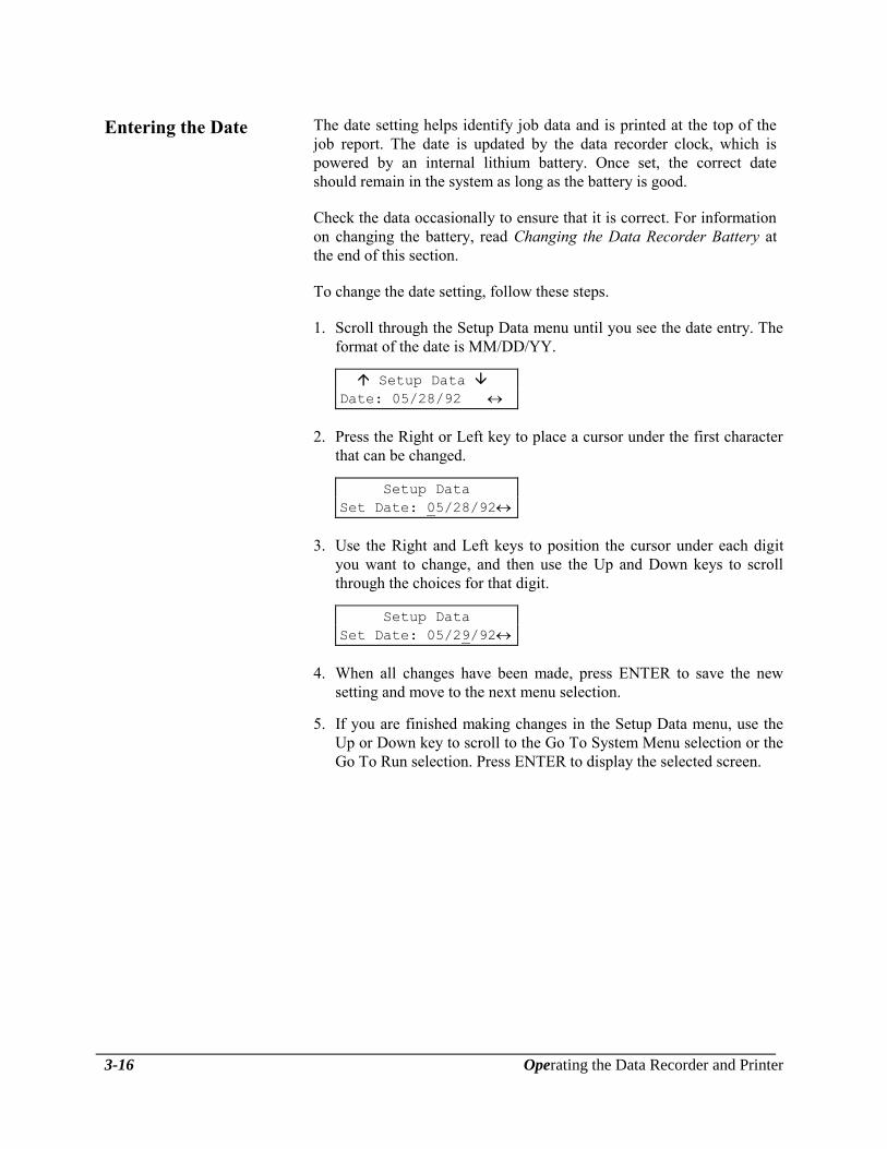
Entering the Date The date setting helps identify job data and is printed at the top of the
job report. The date is updated by the data recorder clock, which is
powered by an internal lithium battery. Once set, the correct date
should remain in the system as long as the battery is good.
Check the data occasionally to ensure that it is correct. For information
on changing the battery, read Changing the Data Recorder Battery at
the end of this section.
To change the date setting, follow these steps.
1. Scroll through the Setup Data menu until you see the date entry. The
format of the date is MM/DD/YY.
Setup Data
Date: 05/28/92
2. Press the Right or Left key to place a cursor under the first character
that can be changed.
Setup Data
Set Date: 05/28/92
3. Use the Right and Left keys to position the cursor under each digit
you want to change, and then use the Up and Down keys to scroll
through the choices for that digit.
Setup Data
Set Date: 05/29/92
4. When all changes have been made, press ENTER to save the new
setting and move to the next menu selection.
5. If you are finished making changes in the Setup Data menu, use the
Up or Down key to scroll to the Go To System Menu selection or the
Go To Run selection. Press ENTER to display the selected screen.

Operating the Data Recorder and Printer 3-17
Entering the Time The time setting is used to identify the job data. The start time and
duration of each lift is printed in the reports. The time is controlled by
the data recorder clock. Once set, the correct time should remain in the
system as long as the battery is good.
Check the time occasionally to ensure that it is correct. For information
on changing the battery, read Changing the Data Recorder Battery at
the end of this section.
To change the time setting, follow these steps.
1. Scroll through the Setup Data menu until you see the time entry. The
format of the time display is HH:MM:SS using a 24-hour clock.
Setup Data
Time: 13:42:58
2. Press the Right or Left key to place a cursor under the first character
that can be changed.
Setup Data
Set Time: 13:42:58
3. Use the Right and Left keys to position the cursor under each digit
you want to change then use the Up and Down keys to scroll through
the choices for that digit.
Setup Data
Set Time: 14:35:00
4. When all changes have been made, press ENTER to save the new
setting and move to the next menu selection.
5. If you are finished making changes in the Setup Data menu, use the
Up or Down key to scroll to the Go To System Menu selection or the
Go To Run selection. Press ENTER to display the selected screen.

3-18 Operating the Data Recorder and Printer
Specifying Flight-Time
Switch Polarity
You set flight-time switch polarity to specify the type of connection
used by the flight-time switch wiring. The correct setting depend on
how this user-supplied switch is installed. There are two menu settings:
High specifies that the switch connects the data recorder to an airframe
ground source during flight; Low specifies that the switch disconnects
the data recorder from airframe ground during flight.
Follow these steps to specify the flight-time switch polarity.
1. Scroll through the Setup Data menu until you see an item like this.
Setup Data
Flt switch:<HIGH>
The angle brackets around the High selection in this example indicate
that when the aircraft is in flight, the flight-time wire of the data
recorder is connected by the switch to airframe ground. When the
aircraft is on the ground, the switch disconnects the wire from
airframe ground.
2. Press the Right or Left key to access the following screen.
Setup Data
Polarity:LOW
3. Use the Right or Left key to toggle between High and Low until the
desired selection is displayed. Select Low if the flight time counts
when the flight-time wire is disconnected from airframe ground.
4. Press ENTER to save the new setting and move to the next menu
item.
5. If you are finished making changes in the Setup Data menu, use the
Up or Down key to scroll to the Go To System Menu selection or the
Go To Run selection. Press ENTER to display the selected screen.
Operating the Data Recorder and Printer 3-19
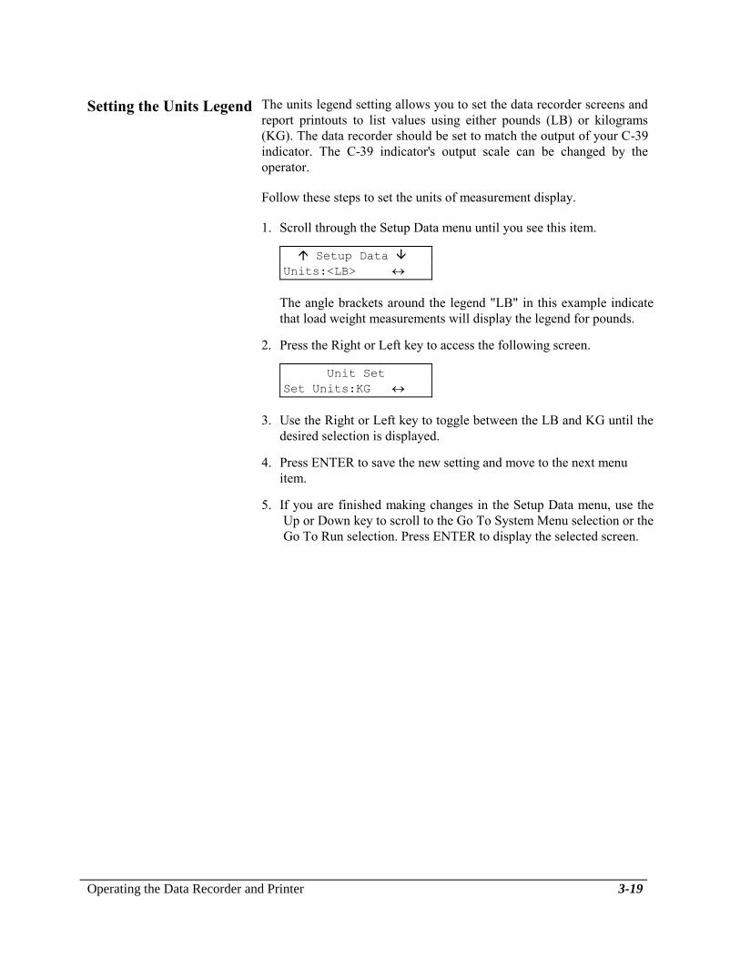
Setting the Units Legend The units legend setting allows you to set the data recorder screens and
report printouts to list values using either pounds (LB) or kilograms
(KG). The data recorder should be set to match the output of your C-39
indicator. The C-39 indicator's output scale can be changed by the
operator.
Follow these steps to set the units of measurement display.
1. Scroll through the Setup Data menu until you see this item.
Setup Data
Units:<LB>
The angle brackets around the legend "LB" in this example indicate
that load weight measurements will display the legend for pounds.
2. Press the Right or Left key to access the following screen.
Unit Set
Set Units:KG
3. Use the Right or Left key to toggle between the LB and KG until the
desired selection is displayed.
4. Press ENTER to save the new setting and move to the next menu
item.
5. If you are finished making changes in the Setup Data menu, use the
Up or Down key to scroll to the Go To System Menu selection or the
Go To Run selection. Press ENTER to display the selected screen.

3-20 Operating the Data Recorder and Printer
Managing the Customer List
The customer list links job data to a particular customer. When work is
performed for several customers, a separate job report can be generated
for each customer. The customer names can be any alphanumeric string
up to nine characters long. Up to ten customers can be entered and this
information will be stored until it is changed.
To enter or edit customer names, follow these steps.
1. Scroll through the System Menu until you see this screen:
System Menu
Manage Customer List
2. Press ENTER and use the Up and Down arrow keys to scroll to the
customer that needs to be changed or added.
3. Press the Right or Left key to place a cursor under the first character
that can be changed.
Customer # 4
_BILL
4. Use the Right and Left keys to position the cursor under each
character you want to change, and then use the Up and Down keys to
scroll through the choices for that character. For example, you might
enter this value.
Customer # 4
JERRY
5. When all changes have been made, press ENTER to save the new
setting and then use the Up and Down keys to scroll to the next
customer.

Operating the Data Recorder and Printer 3-21
Managing the Customer List, continued
6. If you are finished making changes in the Customer List menu, select
the desired customer by using the up and down arrow keys until the
correct customer appears and then press ENTER to get back to the
System Menu.
Be sure that when you exit out of the Manage
Customer List menu, the correct customer has
been selected. The flight information will be
recorded for the customer last selected. To verify
customer or change to another customer, follow
the procedures on the following page.
To access the Customer List menu from the Run screen, follow these
steps.
1. If accessing during flight, press the Up or Down arrow key to end the
turn.
If the turn is not ended and a new customer is
selected, the last lift will be added to the new
customer. Press the Up or Down key to end the
turn.
2. Press the Up and Down arrow keys simultaneously to access the
System Menu. You should see Manage Customer List on the screen,
press ENTER.
3. Follow the guidelines on the previous page to select, add or change
customers.

3-22 Operating the Data Recorder and Printer
Managing the Location List
The location list helps to further describe work done for a particular
customer on the job report. The locations can be changed at any time
between lifts, and the lifts corresponding to each location are indicated
on the report. The locations can be any alphanumeric string up to nine
characters long. Up to ten different locations can be entered and will
remain stored until they are changed.
To enter or edit locations, follow these steps.
1. Scroll through the System menu until you see this screen:
System Menu
Manage Location List
2. Press ENTER and use the Up or Down arrow keys to scroll to the
location that needs to be changed or added.
3. Press the Right or Left key to place a cursor under the first character
that can be changed.
Location # 3
4. Use the Right and Left keys to position the cursor under each
character you want to change, and then use the Up and Down keys to
scroll through the choices for that character. For example, you might
enter this value.
Location # 3
ST. HELENS
5. When all changes have been made, press ENTER to save the new
setting and then use the Up and Down arrow keys to scroll to the next
location.

Operating the Data Recorder and Printer 3-23
Managing the Location List, continued
6. If you are finished making changes in the Location List menu, select
the desired location by using the up and down arrow keys until the
correct location appears and then press ENTER to get back to the
System Menu.
Be sure that when you exit out of the Manage
Location List menu, the correct location has been
selected. The flight information will be recorded
for the location last selected. To verify location
or change to another location, follow the
procedures on the following page.
To access the Location List menu from the Run screen, follow these
steps.
1. If accessing during flight, press the Up or Down arrow key to end the
turn.
If the turn is not ended and a new location is
selected, the last lift will be added to the new
location. Press the Up or Down key to end the
turn.
2. Press the Up and Down arrow keys simultaneously to access the
System Menu. Use the Up or Down arrow keys to scroll to Manage
Location List and then press ENTER.
3. Follow the guidelines on the previous page to add or change
locations.

3-24 Operating the Data Recorder and Printer
Entering Company Data
The Company Data menu allows you to enter standard information about
your company, such as name, address, and phone number. This
information is printed in the header at the top of all reports. Six lines of
20 characters each are available. Entering data on these lines is optional.
To access the Company Data menu from the Run screen, follow these
steps.
1. Press the Up and Down keys simultaneously to access the System
Menu.
2. Use the Up and Down keys to display the Company Data selection.
System Menu
Enter Company Data
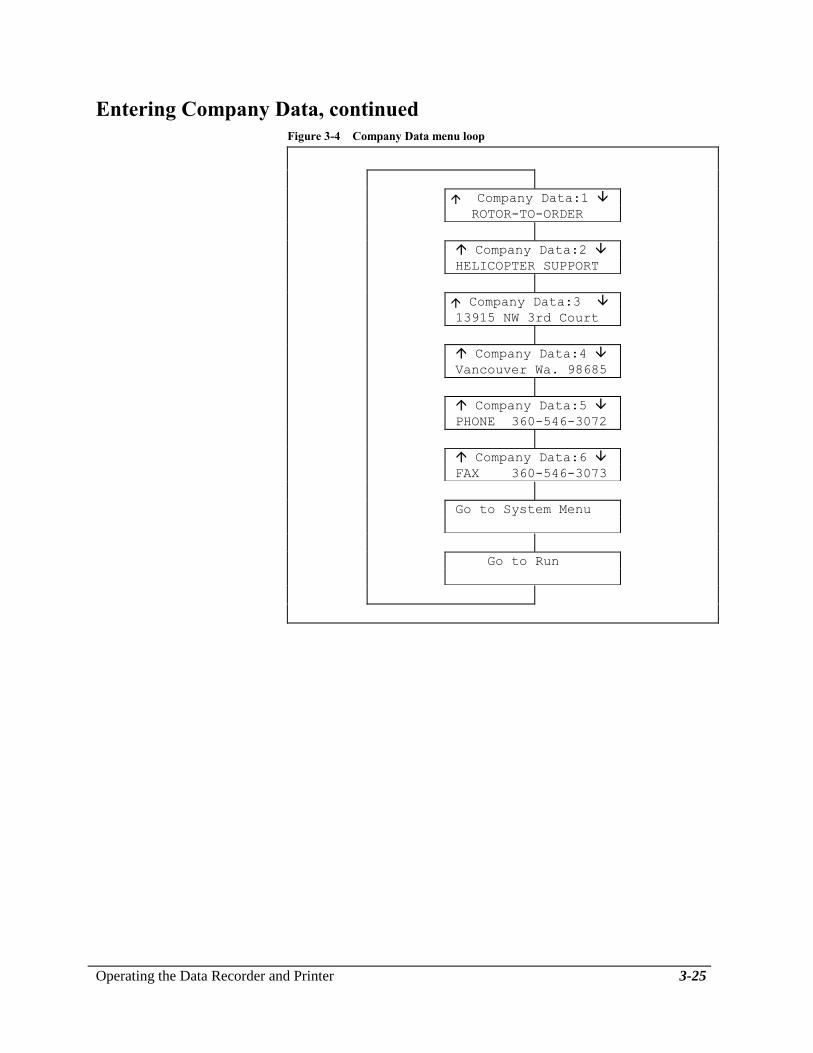
3. Press ENTER. You can now scroll through the lines in the Company
Data menu loop. Figure 3-4 shows the Company Data menu loop
with example entries for the fictional company Rotor-to-Order.
To enter company data, follow these steps.
1. Access the Company Data menu as described above. A display like
this appears.
Company Data:1
2. Press the Right or Left key to access the following screen. A cursor
appears in the first position on the second line of the display.
Enter Company Data:1
3. Use the Up and Down keys to scroll through the character choices —
A-Z, 0-9, space, hyphen, slash, apostrophe, and period. When the
desired character is displayed, use the Right and Left keys to place
the cursor under the next position where you want to change or enter
a character.
4. When all changes have been made to the first line of company data,
press ENTER to save the new setting and move to the next line.
5. Edit Lines 2 through 6 as you did for Line 1.
6. When you are finished, return to the System Menu or the Run screen
by pressing ENTER when the appropriate choice is displayed.
Operating the Data Recorder and Printer 3-25
Entering Company Data, continued
Figure 3-4 Company Data menu loop
Company Data:1
ROTOR-TO-ORDER
Company Data:2
HELICOPTER SUPPORT
Company Data:3
13915 NW 3rd Court
Company Data:4
Vancouver Wa. 98685
Company Data:5
PHONE 360-546-3072
Company Data:6
FAX 360-546-3073
Go to System Menu
Go to Run

3-26 Operating the Data Recorder and Printer
Using the Utilities Menu
The Utilities menu displays the system version number and remaining
data card storage, and allows you to erase a data card.
To access the Utilities menu from the Run screen, follow these steps.
1. Press the Up and Down keys simultaneously to access the System
Menu.
2. Use the Up and Down keys to display the Utilities selection.
System Menu
Utilities
3. Press ENTER. You can now scroll through the lines in the Utilities
menu loop, shown in the example in Figure 3-5.
Figure 3-5 Utilities menu loop
Onboard Systems
Data Recorder 7.1
Main Battery Level
D
C
Card Status
734 recs available
Erase Card
Press RESET to Erase
Go to System Menu
Go to Run
Operating the Data Recorder and Printer 3-27
Viewing the Software
Version Number
The first screen in the Utilities menu displays the version number of the
data recorder software.
To view the version number, follow these steps.
1. Scroll through the Utilities menu until you see a screen similar to this
example.
Onboard Systems
Data Recorder 7.1
2. Press the Down key to move to the next menu screen, or press the Up
key to get the Go to Run screen.
Viewing the Data
Recorder Battery Level
The next screen in the Utilities menu displays a bar chart of the charge
level in the data recorder's internal lithium battery. If the battery level is
low, follow the instructions for Replacing the Data Recorder Battery at
the end of this section.
To view the battery level of the data recorder, follow these steps.
1. Scroll through the Utilities menu until you see this screen.
Main Battery Level
D
C
The "D" stands for "discharged" and the "C" stands for "charged."
Thus the battery that generated the preceding display is charged near
capacity. The battery that generated the following display is nearly
discharged and should be replaced. See Changing the Data Recorder
Battery in this Section.
Main Battery Level
D
C
2. Press the Up or Down key to move to other screens in the menu loop.
3-28 Operating the Data Recorder and Printer
Viewing the Data Card
Status
The data card status shows how many entries can still be stored on the
data card. An entry is any item of information that is stored on the card,
such as customer identifier, product identifier, and lift information. An
8 Kb card can hold 714 entries; a 32 Kb card can hold 2,574 entries.
To view the card status, follow these steps.
1. Scroll through the Utilities menu until you see this screen.
Card Status
534 recs available
The number of available entries decreases as you store more lift
information and resets to the maximum when you erase the card.
If no card is installed, this message appears instead.
Card Status
No Card Installed
2. Press the Up or Down key to move to other screens in the menu loop.

Operating the Data Recorder and Printer 3-29
Erasing the Data Card Erasing a data card deletes all lift information from the card.
Information that has been set using the Setup Data, Customer List,
Location List, and Company Data menus is not erased. Use the
appropriate menu to change this information, if desired.
To erase the data card status, follow these steps.
1. Scroll through the Utilities menu until you see this screen.
Clear Card
Press RESET To Clear
If no card is installed, the following message appears instead.
Clear Card
No Card Installed
Insert the card you want to erase and reselect the Clear Card menu
choice.
2. Press RESET to continue with the erasure sequence. Press any key
other key than RESET to move to the next screen on the Utilities
Menu without erasing the card.
If you press RESET, the following display asks you to confirm
erasure.
Erase All Card Data?
ENTER To Confirm
4. Press the ENTER key to erase the data card, or press any key other
than ENTER to escape from the erase sequence without erasing the
card. The next screen on the Utilities Menu is displayed.
3-30 Operating the Data Recorder and Printer
Using the Run Screen
The Run screen is the screen that appears when you turn on the data
recorder. It is displayed during normal operation and data recording. The
Run screen must be displayed to record lift data. If a screen other than
the Run screen appears on power up, refer to Attention Messages at the
end of this section for more information.
Several types of information can be displayed on the Run screen, as
described in the following paragraphs.
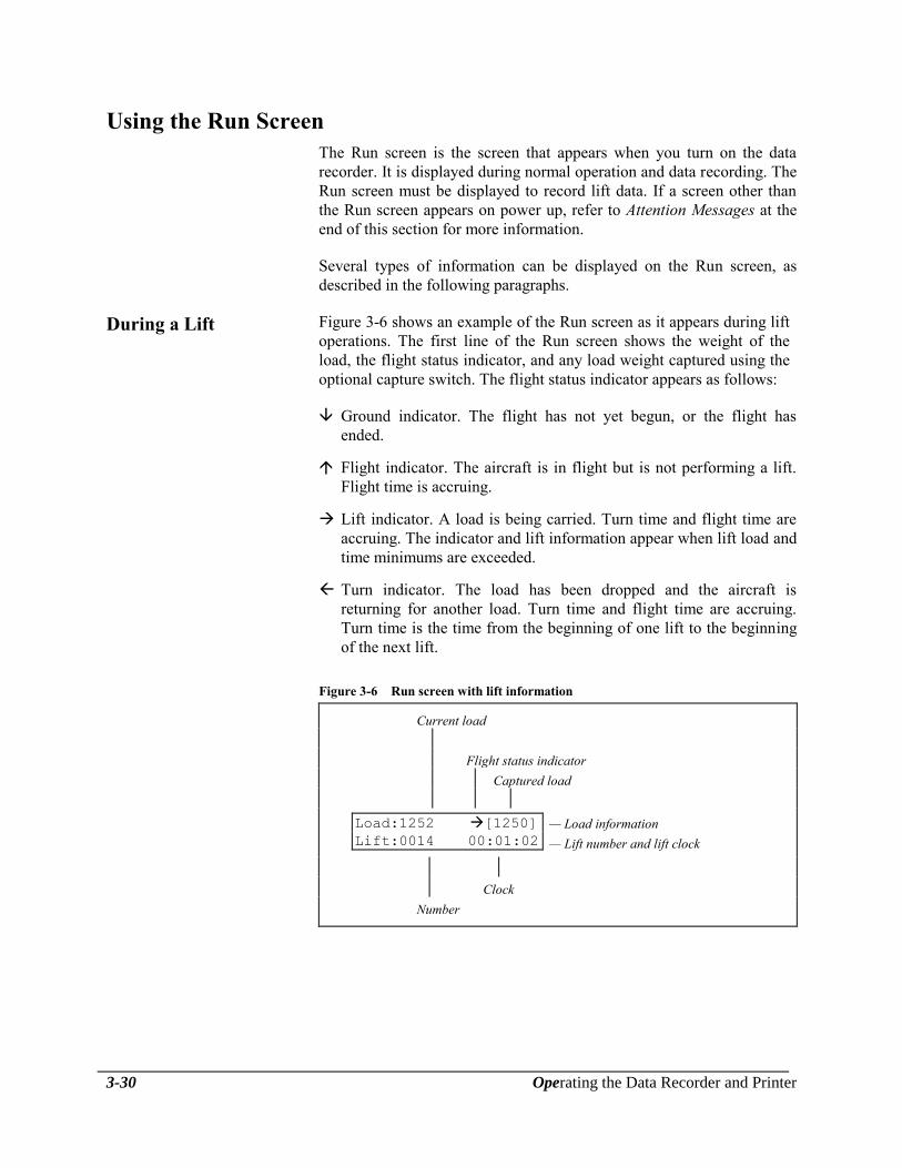
During a Lift Figure 3-6 shows an example of the Run screen as it appears during lift
operations. The first line of the Run screen shows the weight of the
load, the flight status indicator, and any load weight captured using the
optional capture switch. The flight status indicator appears as follows:
Ground indicator. The flight has not yet begun, or the flight has
ended.
Flight indicator. The aircraft is in flight but is not performing a lift.
Flight time is accruing.
Lift indicator. A load is being carried. Turn time and flight time are
accruing. The indicator and lift information appear when lift load and
time minimums are exceeded.
Turn indicator. The load has been dropped and the aircraft is
returning for another load. Turn time and flight time are accruing.
Turn time is the time from the beginning of one lift to the beginning
of the next lift.
Figure 3-6 Run screen with lift information
Current load
Flight status indicator
Captured load
Load:1252 [1250]
Lift:0014 00:01:02
— Load information
— Lift number and lift clock
Clock
Number

Operating the Data Recorder and Printer 3-31
During a Flight The Run screen displays flight information when the aircraft is in flight
but no load is on the hook, or when you have requested flight
information by pressing Right or Left. Figure 3-7 shows an example of
the Run screen displaying flight information.
When no load is on the hook, the second line of the Run screen
automatically shows the sequence number and duration of the flight.
When a load is on the hook, the second line automatically shows the
sequence number and duration of the current lift. To view the flight
number and clock when lift information is displayed, press Right or Left
until the display appears.
Figure 3-7 Run screen with flight information
Flight status indicator
Load: 0
Flight:005 00:12:38
— Flight number and flight clock
Clock
Number

3-32 Operating the Data Recorder and Printer
Viewing Customer
Totals
You can also use the Run screen to display flight and lift totals for a
particular customer. This feature allows you to display summary
customer data in the cockpit when a printer is not available. Two
screens of customer information are available; one shows the number of
flights and total flight time, the other shows the number of lifts and
total load.
To view the customer totals:
1. If needed, use the Manage Customer List menu to set the customer
identifier to the name of the customer whose data you want to view.
2. Return to the Run screen, then press the Right or Left key one or
more times until the desired data is displayed.
If you begin a lift when a customer totals screen is
displayed, the lift data Run screen automatically
appears. The current customer identifier setting is
used to identify the lift.
Figure 3-8 shows examples of the customer totals Run screens.
Figure 3-8 Run screens with customer totals
Johnson Totals
Flight:0005 04:12:38
— Total # of flights and total flight time
Johnson Totals
Lift:0037 18563
— Total # of lifts and total load

Operating the Data Recorder and Printer 3-33
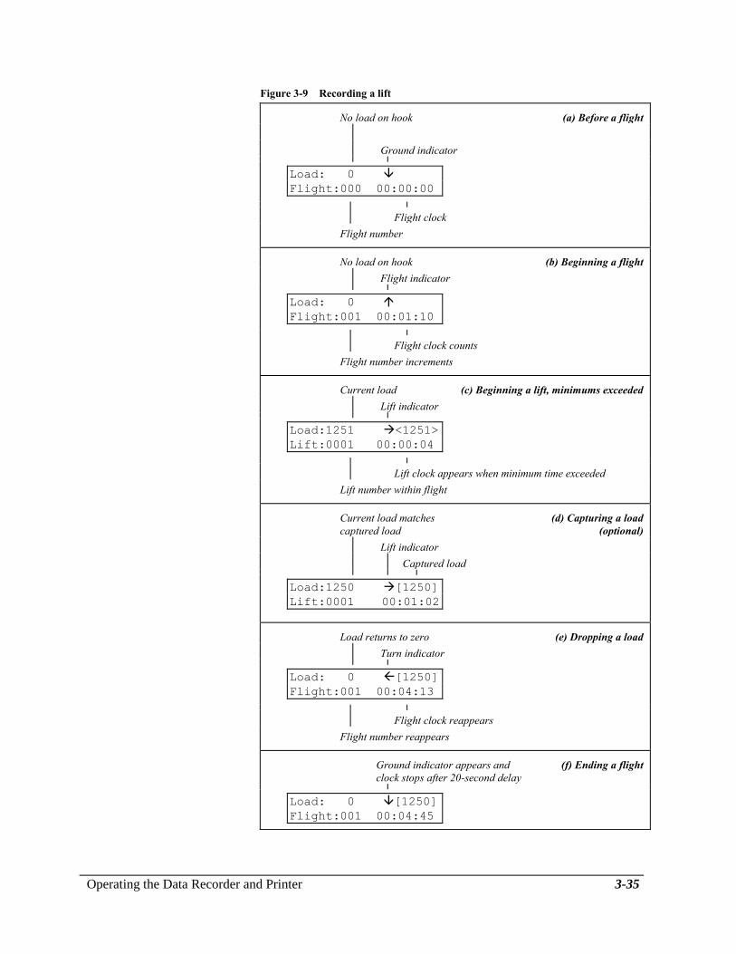
Recording a Lift
This procedure describes the steps you follow to record a lift.
1. Turn on the power to the weighing system and then the data recorder.
2. Use the Setup Data and Company Data menus to change any menu
settings, as needed.
3. Ensure that the Run screen is displayed. See Figure 3-9a.
Load: 0
Flight:000 00:00:00
4. Use the zero control on the weighing system indicator to zero the
load readings both on the indicator and the data recorder.
5. Insert a data card into the data recorder.
You can use the data recorder as a remote
indicator without the data card. However, no lift
information is recorded.
6. Begin the flight or turn on the flight time switch to begin accruing
flight time. The flight counter increments and the ground indicator
changes to the flight indicator . See Figure 3-9b.
Load: 0
Flight:001 00:00:01
7. Begin a lift. In automatic mode, when both the minimum lift time and
minimum lift load are exceeded, the system records a lift. On the Run
screen, the load weight registers and the lift indicator appears. The
lift data line appears, the lift counter increments, and the lift clock
begins counting. See Figure 3-9c.
The system displays and records the full duration of the lift, even if a
minimum lift time is set. For example, if the minimum lift time is
five seconds, the display looks something like this when the lift
indicator first appears.
Load:1251 <1251>
Lift:0001 00:00:05
3-34 Operating the Data Recorder and Printer
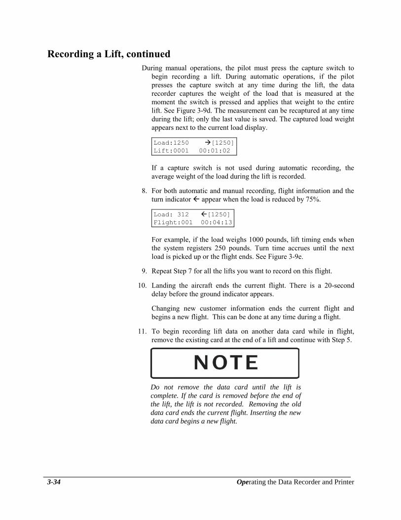
Recording a Lift, continued
During manual operations, the pilot must press the capture switch to
begin recording a lift. During automatic operations, if the pilot
presses the capture switch at any time during the lift, the data
recorder captures the weight of the load that is measured at the
moment the switch is pressed and applies that weight to the entire
lift. See Figure 3-9d. The measurement can be recaptured at any time
during the lift; only the last value is saved. The captured load weight
appears next to the current load display.
Load:1250 [1250]
Lift:0001 00:01:02
If a capture switch is not used during automatic recording, the
average weight of the load during the lift is recorded.
8. For both automatic and manual recording, flight information and the
turn indicator appear when the load is reduced by 75%.
Load: 312 [1250]
Flight:001 00:04:13
For example, if the load weighs 1000 pounds, lift timing ends when
the system registers 250 pounds. Turn time accrues until the next
load is picked up or the flight ends. See Figure 3-9e.
9. Repeat Step 7 for all the lifts you want to record on this flight.
10. Landing the aircraft ends the current flight. There is a 20-second
delay before the ground indicator appears.
Changing new customer information ends the current flight and
begins a new flight. This can be done at any time during a flight.
11. To begin recording lift data on another data card while in flight,
remove the existing card at the end of a lift and continue with Step 5.
Do not remove the data card until the lift is
complete. If the card is removed before the end of
the lift, the lift is not recorded. Removing the old
data card ends the current flight. Inserting the new
data card begins a new flight.
Operating the Data Recorder and Printer 3-35
Figure 3-9 Recording a lift
No load on hook (a) Before a flight
Ground indicator
Load: 0
Flight:000 00:00:00
Flight clock
Flight number
No load on hook (b) Beginning a flight
Flight indicator
Load: 0
Flight:001 00:01:10
Flight clock counts
Flight number increments
Current load (c) Beginning a lift, minimums exceeded
Lift indicator
Load:1251 <1251>
Lift:0001 00:00:04
Lift clock appears when minimum time exceeded
Lift number within flight
Current load matches (d) Capturing a load
captured load (optional)
Lift indicator
Captured load
Load:1250 [1250]
Lift:0001 00:01:02
Load returns to zero (e) Dropping a load
Turn indicator
Load: 0 [1250]
Flight:001 00:04:13
Flight clock reappears
Flight number reappears
Ground indicator appears and (f) Ending a flight
clock stops after 20-second delay
Load: 0 [1250]
Flight:001 00:04:45
3-36 Operating the Data Recorder and Printer
Using the Optional Printer
The following paragraphs describe how to use the C-23 Printer. They
describe how to turn on the printer, print a self-test, install paper, install
a ribbon, clear a printer jam, and how to print and read a lift report from
a data card.
Turning on the Printer The C-23 Printer should be turned on after the load weigh system is
powered up. The power switch has three positions. The OFF position
is all the way to the left, the ON position is in the center, and the
PAPER FEED position is all the way to the right. To turn the printer
on, follow these steps.
1. Turn on the printer by pushing the POWER switch down on the right
side. Now release the switch and it will remain in the center ON
position.
2. The power LED should now be lit and a READY message should
have been printed.
3. When turning the printer off, wait at least 3 seconds before turning
the printer back on.
Printing a Self-Test The print head and ribbon can be tested only after inserting paper. Do
not print without paper. To print a self-test follow these steps.
1. Make sure the printer is in the OFF position.
2. Depress power switch until it reaches PAPER FEED position.
3. Hold the switch in the PAPER FEED position until the LED light
goes on and the printer starts to operate. Release switch.
4. To stop the printer during the self-test or at any other time, turn the
power switch to the OFF position and wait 3 seconds to turn it back
on.
Installing the Paper The C-23 printer uses a 2.25-inch roll paper, available as Part Number
215-051-00. To install a roll of paper in the printer compartment,
follow these steps.
1. Press the power switch to the OFF position.
2. There are small grooves embossed on the printer cover, push down
on the grooves using both your index fingers. The printer cover will
tilt up, then lift the lid completely off.
3. Unroll several inches of the paper. Cut a straight edge on the paper
roll if it is jagged. This will facilitate the entry of the paper into the
printer.

Operating the Data Recorder and Printer 3-37
Installing the Paper,
continued
4. Slide the paper through the slot connecting the paper compartment
and the printer compartment. You can slide it in about one-quarter
inch before it stops.
5. Press the power switch to the ON position and wait for a few
seconds.
6. While holding the paper in place, press the power switch to the
PAPER FEED position. The printer will activate, and a rubber roller
will pull the paper into the printer compartment. Hold the switch in
the PAPER FEED position until the paper emerges from the top of
the printer mechanism. When an inch of paper has emerged from the
top of the printer, release the PAPER FEED button.
7. Now pull the paper through the printer, until several inches are
exposed.
8. Replace the printer cover by sliding the paper through the slot in the
printer cover. Push the back of the printer cover down and into
place. Press the front of the printer cover down to lock in place.
9. Put the paper roll holder into the paper roll and place the holder onto
the grooves near the back of the printer. Turn the paper roll so as to
take up any slack in the paper feeding to the printer. Make sure the
roll of paper moves freely. If it does not move freely, the paper will
jam and will possibly damage the printer mechanism.
Installing the Cartridge
Ribbon
When printing becomes faint or difficult to see, the cartridge should be
replaced. The ribbon is available as Part Number 212-006-00. To
install a cartridge ribbon in the printer, follow these steps.
1. Press the power switch into the OFF position.
2. Remove the printer cover following the procedures above.
3. Push down on the right side of the ribbon cartridge (marked "PUSH")
and remove the cartridge.
4. Install the new cartridge. Be sure the ink cartridge is inserted firmly
to prevent weak or irregular printing. The cartridge must be properly
seated and aligned for best printing.
5. Turn the cartridge "knob" (marked be an arrow) clockwise to stretch
the ribbon.
6. Replace the cover following the procedures above.
7. Replace the paper.
3-38 Operating the Data Recorder and Printer
Installing the Cartridge
Ribbon, continued
You may also insert the ribbon cartridge if there is already paper in the
printer. Follow the steps above. Slide the cartridge over the paper and
into the printer compartment. Be sure the paper goes between the
ribbon cartridge and the ink ribbon.
If ribbon ink gets on the printer case, wipe it off
immediately. Once it dries, it is difficult to
remove.
Clearing a Paper Jam If paper jams in the C-23 Printer, follow these steps to clear the jam.
1. Press the power switch into the OFF position.
2. Remove the printer cover following the procedures on the previous
page.
3. To remove the paper roll, lift the paper roll away from the printer
housing. With a pair of scissors cut the paper feeding to the printer.
Try to make the cut as square as possible to facilitate the next
reloading of the paper. Now pull the remaining paper through the
printer mechanism. Be sure to pull the paper from the front (paper
cutter side).
Never pull the paper backwards from the printer.
4. Carefully clear the jam, and replace the printer cover.

Operating the Data Recorder and Printer 3-39
Printing a Report The C-23 Printer can print a report whenever and as often as needed.
Printing a report does not erase or change the information stored in the
data card.
A full report or a summary can be printed for either a single customer
or all customers. Table 3-1 shows the possible types of report
selections.
Follow these steps to print a lift report from a data card.
1. Insert the data card that contains the data to be printed.
2. Press the ENTER button while the Run screen is displayed. The print
format selection screen appears.
Print Format
Format: <Summary>
3. Use the Right or Left keys to select Summary to print summary
information about the lifts, or select Report to print a full lift report.
4. Press ENTER to enter your selection and display the next screen, the
customer selection screen.
Select Customer
Select:HAYES ENT
5. Press the Right or Left key to loop through the list of customer with
data stored on the card until the desired name is displayed, or display
ALL to print data for all customers.
6. Press ENTER to enter your selection and print the report.
Table 3-1 Reports types and their screen selections
Report type FORMAT screen CUSTOMER ID
screen
Full report, all customers REPORT ALL
Full report, one customer REPORT <customer>
Summary, all customers SUMMARY ALL
Summary, one customer, SUMMARY <customer>
3-40 Operating the Data Recorder and Printer
Reading a Report The information printed in a data recorder report or summary depends
on the options you select when you request the report. All reports show
sections that contain company data and summary flight statistics. A full
report includes sections with detailed lift logs by customer.
The various report sections contain the following information.
The report header contains the information stored in Lines 1 – 6 of
the Company Data menu.
The customer header lists information stored in the Setup menu,
including customer identification and location, and aircraft and pilot
identification.
The date is the date the information was stored.
The flight detail includes a header with flight number, start time, end
time and duration; lift detail for each lift, including lift number, load,
start time, load and time minimum designator, and turn time; and an
end-of-flight footer.
The flight summary supplies the number of flights and lifts for the
customer, and totals and averages for flight time, weight, and turn
time.
The codes for minimum settings are automatically assigned by the
system whenever a lift is performed with a different combination of
minimum load and minimum lift time. These codes are designated by
letters, starting with A, that appear next to the start time in the lift
detail. An asterisk * indicates the weight of a load that was captured.
The report footer shows the model number and manufacturer
information for the printer.
Figure 3-11 is an example of a full report from a data card storing
information about two customers; Figure 3-12 is a summary for one of
those customers. Table 3-2 shows which report sections are printed on a
report and a summary.
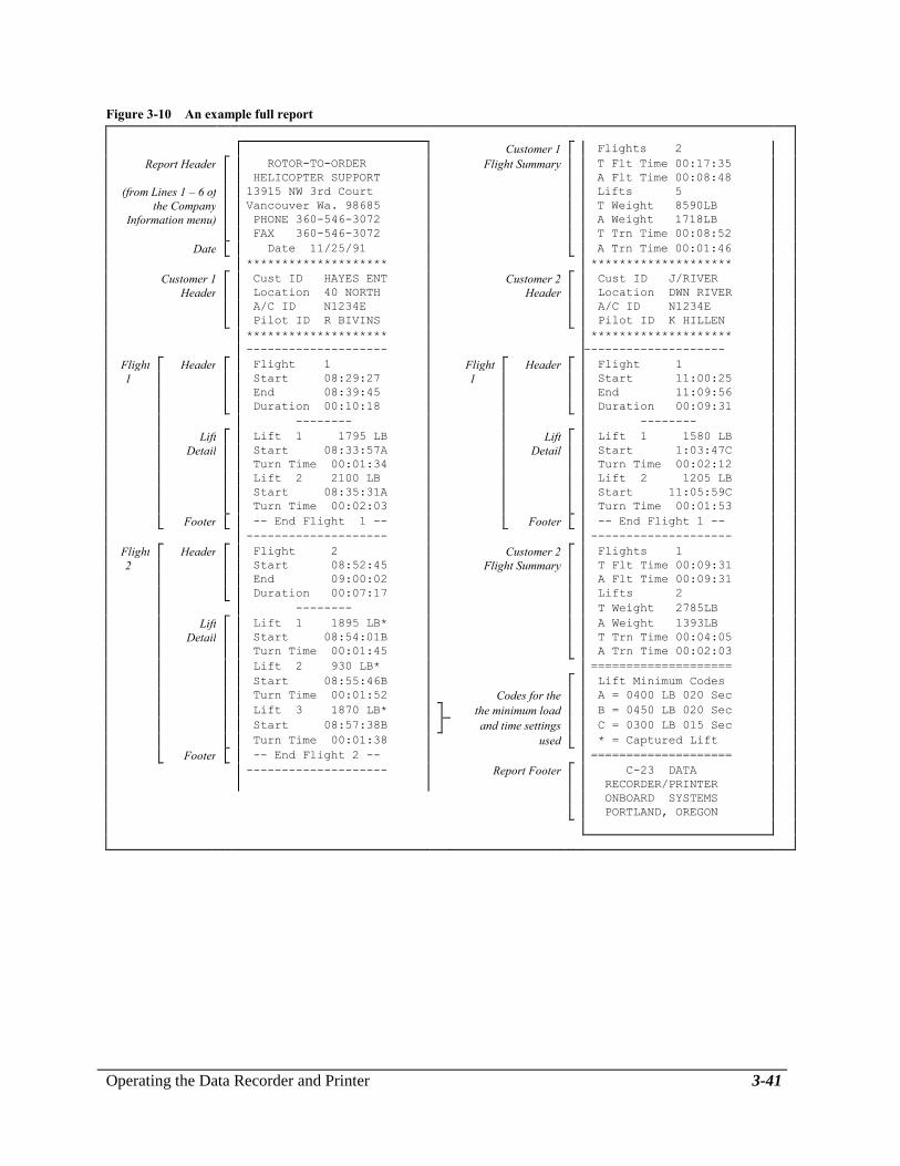
Operating the Data Recorder and Printer 3-41
Figure 3-10 An example full report
Customer 1 Flights 2
Report Header ROTOR-TO-ORDER Flight Summary T Flt Time 00:17:35
HELICOPTER SUPPORT A Flt Time 00:08:48
(from Lines 1 – 6 of 13915 NW 3rd Court Lifts 5
the Company Vancouver Wa. 98685 T Weight 8590LB
Information menu) PHONE 360-546-3072 A Weight 1718LB
FAX 360-546-3072 T Trn Time 00:08:52
Date Date 11/25/91 A Trn Time 00:01:46
******************** ********************
Customer 1 Cust ID HAYES ENT Customer 2 Cust ID J/RIVER
Header Location 40 NORTH Header Location DWN RIVER
A/C ID N1234E A/C ID N1234E
Pilot ID R BIVINS Pilot ID K HILLEN
******************** ********************
-------------------- --------------------
Flight Header Flight 1 Flight Header Flight 1
1 Start 08:29:27 1 Start 11:00:25
End 08:39:45 End 11:09:56
Duration 00:10:18 Duration 00:09:31
-------- --------
Lift Lift 1 1795 LB Lift Lift 1 1580 LB
Detail Start 08:33:57A Detail Start 1:03:47C
Turn Time 00:01:34 Turn Time 00:02:12
Lift 2 2100 LB Lift 2 1205 LB
Start 08:35:31A Start 11:05:59C
Turn Time 00:02:03 Turn Time 00:01:53
Footer -- End Flight 1 -- Footer -- End Flight 1 --
-------------------- --------------------
Flight Header Flight 2 Customer 2 Flights 1
2 Start 08:52:45 Flight Summary T Flt Time 00:09:31
End 09:00:02 A Flt Time 00:09:31
Duration 00:07:17 Lifts 2
-------- T Weight 2785LB
Lift Lift 1 1895 LB* A Weight 1393LB
Detail Start 08:54:01B T Trn Time 00:04:05
Turn Time 00:01:45 A Trn Time 00:02:03
Lift 2 930 LB* ====================
Start 08:55:46B Lift Minimum Codes
Turn Time 00:01:52 Codes for the A = 0400 LB 020 Sec
Lift 3 1870 LB* the minimum load B = 0450 LB 020 Sec
Start 08:57:38B and time settings C = 0300 LB 015 Sec
Turn Time 00:01:38 used * = Captured Lift
Footer -- End Flight 2 -- ====================
-------------------- Report Footer C-23 DATA
RECORDER/PRINTER
ONBOARD SYSTEMS
PORTLAND, OREGON

3-42 Operating the Data Recorder and Printer
Figure 3-11 An example summary for Customer 1
Report Header ROTOR-TO-ORDER
HELICOPTER SUPPORT
., 13915 NW 3rd Court
Vancouver Wa. 98685
PHONE 360-546-3072
FAX 360-546-3073
Date Date 11/25/91
********************
Customer 1 Cust ID HAYES ENT
Header Location 40 NORTH
A/C ID N1234E
Pilot ID R BIVINS
********************
--------------------
Customer 1 Flights 2
Flight Summary T Flt Time 00:17:35
A Flt Time 00:08:48
Lifts 5
T Weight 8590LB
A Weight 1718LB
T Trn Time 00:08:52
A Trn Time 00:01:46
====================
Report Footer C-23 DATA
RECORDER/PRINTER
ONBOARD SYSTEMS
PORTLAND, OREGON
Table 3-2 Sections printed on a report or a summary
Report section REPORT SUMMARY
Report header X X
Date X X
Customer header X X
Flight information X
Flight summary X X
Codes for minimum settings X
Report footer X X

Operating the Data Recorder and Printer 3-43
Changing the Data Recorder Battery
When the data recorder is turned on, it is powered by the aircraft
electrical system. When the data recorder is turned off or is
disconnected, its internal memory is maintained by a lithium battery
inside the data recorder. Each data recorder is shipped from the factory
with a battery in place. Figure 3-13 shows the position of the battery.
You can check the battery power level by viewing the Main Battery
Level item on the Utilities menu. This item shows the level of charge in
the data recorder battery.
If the battery power is high, the screen appears something like this.
("D" stands for "discharged" and "C" stands for "charged.")
Main Battery Level
D
C
If the battery power is low, the screen looks more like this and the
battery should be replaced.
Main Battery Level
D
C
For more information on accessing the Utilities menu to view the data
recorder battery level, read Using the Utilities Menu and Viewing the
Data Recorder Battery Level earlier in this section.
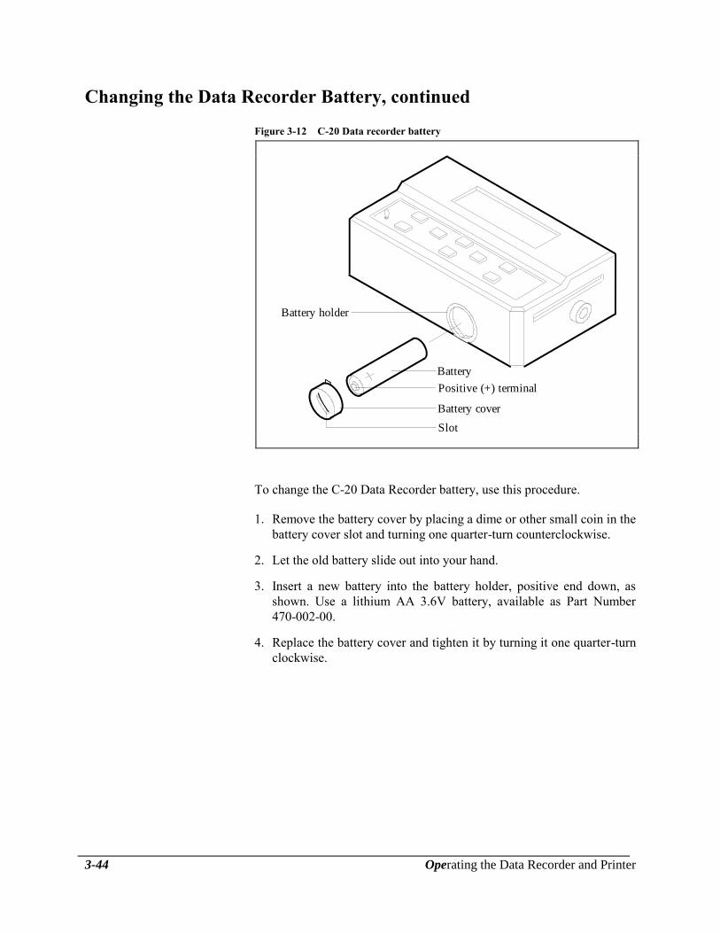
3-44 Operating the Data Recorder and Printer
Changing the Data Recorder Battery, continued
Figure 3-12 C-20 Data recorder battery
Battery holder
Battery
Positive (+) terminal
Battery cover
Slot
To change the C-20 Data Recorder battery, use this procedure.
1. Remove the battery cover by placing a dime or other small coin in the
battery cover slot and turning one quarter-turn counterclockwise.
2. Let the old battery slide out into your hand.
3. Insert a new battery into the battery holder, positive end down, as
shown. Use a lithium AA 3.6V battery, available as Part Number
470-002-00.
4. Replace the battery cover and tighten it by turning it one quarter-turn
clockwise.
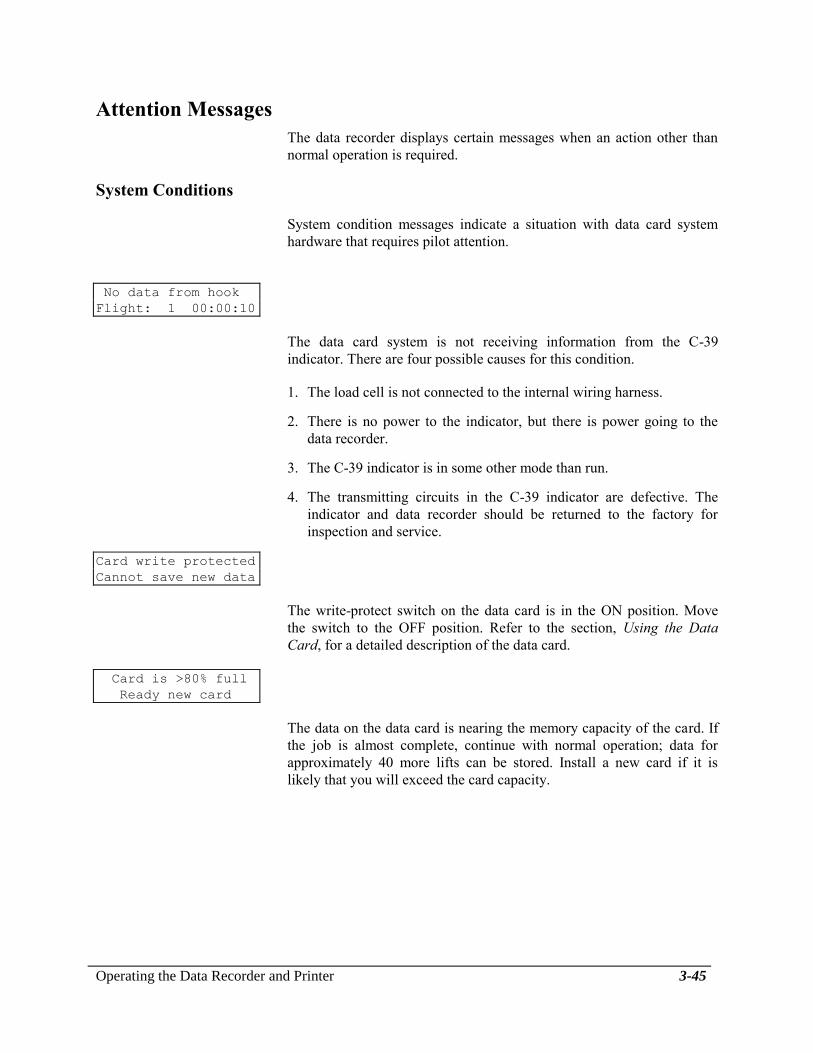
Operating the Data Recorder and Printer 3-45
Attention Messages
The data recorder displays certain messages when an action other than
normal operation is required.
System Conditions
System condition messages indicate a situation with data card system
hardware that requires pilot attention.
No data from hook
Flight: 1 00:00:10
The data card system is not receiving information from the C-39
indicator. There are four possible causes for this condition.
1. The load cell is not connected to the internal wiring harness.
2. There is no power to the indicator, but there is power going to the
data recorder.
3. The C-39 indicator is in some other mode than run.
4. The transmitting circuits in the C-39 indicator are defective. The
indicator and data recorder should be returned to the factory for
inspection and service.
Card write protected
Cannot save new data
The write-protect switch on the data card is in the ON position. Move
the switch to the OFF position. Refer to the section, Using the Data
Card, for a detailed description of the data card.
Card is >80% full
Ready new card
The data on the data card is nearing the memory capacity of the card. If
the job is almost complete, continue with normal operation; data for
approximately 40 more lifts can be stored. Install a new card if it is
likely that you will exceed the card capacity.

3-46 Operating the Data Recorder and Printer
Card full
Cannot save new data
The data card cannot save additional data and the system is no longer
collecting data. Replace the card with one that is not full or see Erasing
the Data Card earlier in this section to erase the card.
Replace card battery
while card installed
The battery in the data card is low. Replace the battery as described in
the section, Using the Data Card. Unless the card is installed in a
powered-up data recorder or data card reader during battery replacement,
any data on the card is lost.
Card Status Messages
These messages are generated by functions on the Utilities menu if you
attempt to perform the operation when no card is installed.
Card Status
No Card Installed
The card status function normally displays the number of entries
available on the card. Install a card to find out this information.
Erase Card
No Card Installed
Install the card you want to erase.

Using the Data Card 4-1
Section 4
Using the Data Card
The C-22 Data Card stores the data that is generated by the weighing
system and the data recorder clock. This section describes the data card
and its use. Here are the topics in this section.
Inserting the Data Card shows how to insert the data card into the
data recorder or data card reader.
Setting the Write-Protect Switch describes how to protect the data
card from accidental erasure.
Replacing the Data Card Battery describes how to replace the battery
in the data card.
Erasing the Data Card describes how to erase information that is
stored on the data card.
Memory Capacity of the Data Card describes the type and amount of
information that is stored on the data card.

4-2 Using the Data Card
Inserting the Data Card
To record data, the write-protect switch on the edge of the card must be
in the OFF position. If no data card is installed, the data recorder
displays the current job information, but the information is not saved.
To insert the data card refer to Figure 4-1 and follow these steps.
1. Hold the data card so that the large striped arrow is visible and the
arrow is pointing toward the card slot on the right side of the data
recorder.
2. Gently guide the card straight into the slot. Do not force the card.
3. Press firmly but gently until the card seats. If a display other than the
Run screen appears, refer to the Attention Messages at the end of the
section Operating the Data Recorder.
Figure 4-1 Inserting the data card
1. Insert card in slot.
2. Press firmly but gently until card seats.
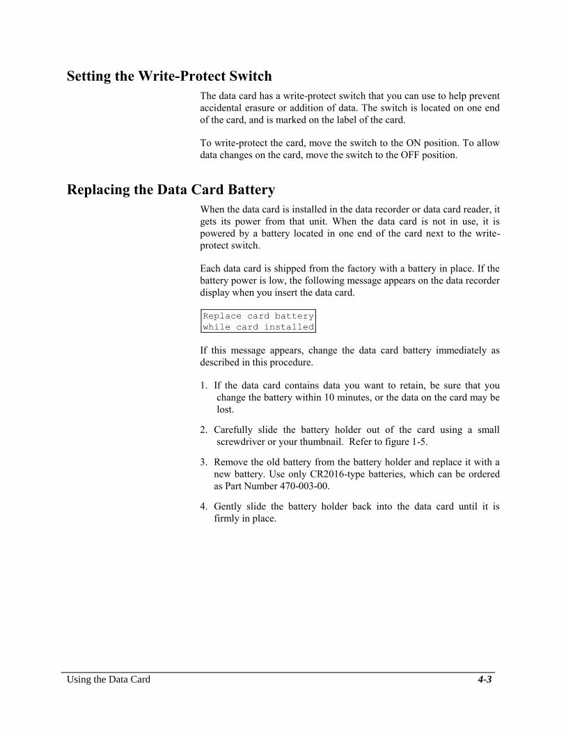
Using the Data Card 4-3
Setting the Write-Protect Switch
The data card has a write-protect switch that you can use to help prevent
accidental erasure or addition of data. The switch is located on one end
of the card, and is marked on the label of the card.
To write-protect the card, move the switch to the ON position. To allow
data changes on the card, move the switch to the OFF position.
Replacing the Data Card Battery
When the data card is installed in the data recorder or data card reader, it
gets its power from that unit. When the data card is not in use, it is
powered by a battery located in one end of the card next to the write-
protect switch.
Each data card is shipped from the factory with a battery in place. If the
battery power is low, the following message appears on the data recorder
display when you insert the data card.
Replace card battery
while card installed
If this message appears, change the data card battery immediately as
described in this procedure.
1. If the data card contains data you want to retain, be sure that you
change the battery within 10 minutes, or the data on the card may be
lost.
2. Carefully slide the battery holder out of the card using a small
screwdriver or your thumbnail. Refer to figure 1-5.
3. Remove the old battery from the battery holder and replace it with a
new battery. Use only CR2016-type batteries, which can be ordered
as Part Number 470-003-00.
4. Gently slide the battery holder back into the data card until it is
firmly in place.

4-4 Using the Data Card
Erasing the Data Card
Once you are finished with the data collected on a card, you can use the
data recorder to erase the card and reuse it indefinitely. To erase a card,
the write-protect switch on the card must be in the OFF position.
Erasing a data card deletes lift information from the card. Information
that has been set using the Setup Data and Company Data menus is not
deleted from the card. Use the appropriate menu to change this
information, if desired.
To erase a data card using the data recorder, follow these steps.
1. Insert the card you want to erase into the data card slot on the side
of the data recorder.
2. When the Run screen is displayed, press the Up and Down arrow
keys simultaneously to enter the System Menu.
3. Use the Up or Down arrow key to move to the Utilities menu
selection.
System Menu
Utilities
4. Press ENTER.
5. Use the Up or Down arrow key to move to the selection for erasing a
data card.
Clear Card
Press RESET To Clear
6. Press RESET to continue with the erasure sequence. Press any key
other key than RESET to move to the next screen on the Utilities
Menu without erasing the card.
If you press RESET, the following display asks you to confirm
erasure.
Erase All Card Data?
ENTER To Confirm
7. Press the ENTER key to erase the data card, or press any key other
than ENTER to escape from the erase sequence and move to the next
screen on the Utilities Menu without erasing the card.
If you press ENTER, the card is erased, and the next screen on the
Utilities Menu is displayed.
Using the Data Card 4-5
Memory Capacity of the Data Card
Data cards are available in two memory capacities, 8 Kb and 32 Kb. The
8 Kb card holds 714 data entries. The 32 Kb card holds 2,574 data
entries. Data entries can be any of the following values.
Data entered using the Setup Data menu including customer,
location, pilot, and aircraft identifiers; and minimum lift time and
load.
Information entered using the Company Data menu.
Data collected from the weighing system and from the data recorder
clock, including weight of a load, flight start time and duration, and
lift start time and duration.
The data recorder and data card reader use this information to compute
averages and totals and generate reports.

This page intentionally left blank.

Operating the Data Card Reader 5-1
Section 5
Operating the Data Card Reader
This section describes how to operate the C-24 Data Card Reader.
Using a Serial or Parallel Printer
You can print reports directly from a data card when the data card reader
is connected to a standard office serial or parallel printer.
Connecting the Printer Connect the data card reader to the printer as described in the section
Installing the System.
Operating the Printer To print a report on the printer, follow these steps.
1. Ensure that the printer power is on and that it is on line.
2. Ensure that the data card reader power is on.
3. Insert the data card to be read gently but firmly into the card slot on
the front of the data card reader. The report begins printing. Figure
5-1 shows an example.
It may be necessary to adjust the settings on the
printer for the reader to print the report properly.
Try toggeling the settings for “Carriage Return”
and/or “Line Feed”.
Using an IBM PC-Compatible Computer
You can display, print, and save data card information when the data
card reader is connected to a personal computer
Connecting the
Computer
Connect the data card reader to the computer as described in Section 2,
Installing the Data Card Reader.
See Section 6, Using the Optional Software, for instructions on loading
and using the software.

5-2 Operating the Data Card Reader
Reading the Printed Report
Figure 5-1 Typical customer report
ROTOR-TO-ORDER
HELICOPTER SUPPORT
13915 NW 3rd Court Report
Vancouver Washington 98685 header
PHONE 360-546-3072
FAX 360-546-3073
==================================================================
Customer: USFS R1
Location: UP RIVER
Customer
Aircraft:N12345678 header
Pilot: R DEVOE
May 28, 1992
------------------------------------------------------------------
Lift # Load Start Time Turn Time Notes
------------------------------------------------------------------
Flight: 1 1 1795 LB 08:33:57 00:01:34 A
Strt 08:29:27 2 2100 LB 08:35:31 00:02:03 A Flight 1
End 08:39:45 detail
Dur 00:10:18
Flight: 2 1 1895 LB* 08:54:01 00:01:45 B
Strt 08:52:45 2 930 LB 08:55:46 00:01:52 B Flight 2
End 09:00:02 3 1870 LB 08:57:38 00:01:38 B detail
Dur 00:07:17
----------------------Totals & Averages----------------------
Flights: 2 Lifts: 5
Total Flight Time: 00:17:35 Total Weight: 8590LB Flight
Average Flight Time: 00:08:48 Average Weight: 1718LB summary
Total Turn Time: 00:08:52
Average Turn Time: 00:01:46
==================================================================
Notes:
* Lift weight captured by operator
Notes
Lift recognition thresholds:
A 400 LB 15 Seconds
B 400 LB 20 Seconds
==================================================================
By ONBOARD SYSTEMS Report
Vancouver Washington footer
C-24 Data Card Reader V7.00

Operating the Data Card Reader 5-3
The data card reader uses the following rules in printing a report.
If the customer changes, a new report is generated with a new header
and setup data information. The lift count and summary data
calculations are restarted.
If the aircraft identifier changes, a banner line is printed showing the
identifier change, and the lift count and summary data calculations
are restarted.
If the location, pilot, or date changes, a banner line is printed
showing the change.
The notes shown at the bottom of each customer report explain the
load and lift time minimums in effect during each lift.

This page intentionally left blank.
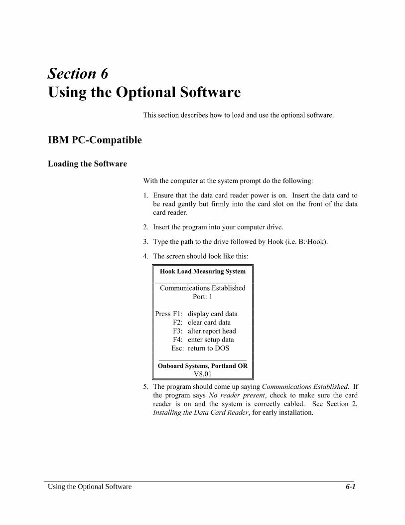
Using the Optional Software 6-1
Section 6
Using the Optional Software
This section describes how to load and use the optional software.
IBM PC-Compatible
Loading the Software
With the computer at the system prompt do the following:
1. Ensure that the data card reader power is on. Insert the data card to
be read gently but firmly into the card slot on the front of the data
card reader.
2. Insert the program into your computer drive.
3. Type the path to the drive followed by Hook (i.e. B:\Hook).
4. The screen should look like this:
Hook Load Measuring System
______________________
Communications Established
Port: 1
Press F1: display card data
F2: clear card data
F3: alter report head
F4: enter setup data
Esc: return to DOS
________________________
Onboard Systems, Portland OR
V8.01
5. The program should come up saying Communications Established. If
the program says No reader present, check to make sure the card
reader is on and the system is correctly cabled. See Section 2,
Installing the Data Card Reader, for early installation.

6-2 Using the Optional Software
Loading the Software,
continued
This software can read four four different serial
ports. To access a given port type “Hook [num].”
Num is the serial port number(1-4), the default is
port 1.
From this main menu, you can choose any of the following commands,
as described in detail below.
Main Menu F1:
Display Card Data
Pressing F1 from the main menu will allow you to view the information
on the inserted data card. If more than one customer is on the data card a
screen will display all the customers.
Select Customer
_______________
JOHN S.
ROB D.
DON S.
CHARLY M.
GEORGE T.
FRANKE S.
JASON L.
Select the desired customer by using the up or down arrow keys on your
computer, and then press Enter.

Using the Optional Software 6-3
Main Menu F1:
Display Card Data,
continued
After a customer has been selected the screen will display the
information below.
Flight Start Duration Lift Load(Lb) Start Time Turn Time Notes
______________________________________________________________________________
**** Location: Lot 41 ****
**** Date: July 6, 1993 ****
**** Pilot: R Devoe ****
**** Aircraft: N12345678 ****
1 11:36:08 00:31:24 1 597 11:36:31 00:00:18 A
2 597 11:36:49 00:00:17 A
3 599 11:37:06 00:00:18 A
4 597 11:37:24 00:00:18 A
5 599 11:37:42 00:00:18 A
6 598 11:38:00 00:00:18 A
7 598 11:38:18 00:00:17 A
8 598 11:38:35 00:00:18 A
9 599 11:38:53 00:00:17 A
10 597 11:39:10 00:00:18 A
11 599 11:39:28 00:00:18 A
12 599 11:39:46 00:00:18 A
13 599 11:40:04 00:00:17 A
14 597 11:40:21 00:00:18 A
15 597 11:40:39 00:00:18 A
16 597 11:40:57 00:00:17 A
17 598 11:41:14 00:00:18 A
PgUp:Prev PgDn:Next F1:Customer F2:Location F4:Info F5:File F6:Print
Located at the bottom of the screen are commands to do a variety of
things.
Display Card Data
PgUp and PgDn
You can view the pages of flight data by using the PgUp and PgDn keys
on the keyboard. Press PgUp to see the previous page and PgDn to see
the next page.
Display Card Data
F1: Customer
Pressing F1 will allow you to select another customer and view the flight
information without having to go back to the main menu.

6-4 Using the Optional Software
Display Card Data
F2: Location
If a customer has flown in more than one location, pressing F2 will
allow you to select a different location.
Select Location
_______________
JOHNS CRK
MEADOW 1
BALD MTN
DN RIVER
UP RIVER
LOT 441
Select the desired location by using the up or down arrow keys on your
computer, and then press Enter to view the flight information for that
selected location.
Display Card Data
F4: Info
If you want to quickly view total flights, average lift time, or something
related, press F4 and this summary information will be displayed.
Summary Information
____________________________________________________________
HELICOPTER SUPPORT
13915 NW 3rd Court
AIRPORT HANGER
Vancouver Washington 98685
-----------------------------------
555-FLY-AWAY
Customer: JERRY
Total Flights: 1 Total Lifts: 105
Total Flight Time: 00:31:24 Total Lift Time: 00:30:58
Average Flight Time: 00:31:24 Average Lift Time: 00:00:17
Average Weight(Lb): 597 Total Weight(Lb): 62769
Notes:
__________________________________________________________
* Lift weight captured by operator
A 300 Lb 3 Seconds

Using the Optional Software 6-5
Display Card Data
F5: File
If you would like to save the flight information for the customer selected
on a disk or on the hard drive of your computer, press F5. You will be
given the following screen, asking whether you would like to save the
complete flight information or a summary of the information (summary
information is pictured above).
Report Type
F1: Complete
F2: Summary
Press F1 or F2 and then type the directory or file you want the data saved
in.
Display Card Data
F6: Prnt
Pressing F6 will allow you to print the complete flight information or a
summary. If you press F6, you will be given the same window as F5,
asking for the report type, complete or summary.
Main Menu F2:
Clear Card Data
F2 allows you to erase all the information on the data card. Pressing F2
will give the following window, asking if you really want to clear the
data card. Press either Y or N and press Enter.
All data in this card will
be lost, are you sure you
want to clear this card?
(Y)es or (N)o: _

6-6 Using the Optional Software
Main Menu F3:
Alter Report Head
F3 allows you to change the heading on your report. Pressing F3 will
give the following window with your own heading that was previously
entered in the data recorder:
Select line to change:
Lines will be centered on reports.
F1: "HELICOPTER SUPPORT "
F2: "13915 NW 3rd Court "
F3: "AIRPORT HANGER "
F4: " Vancouver Wa. 98685 "
F5: "-----------------------------------"
F6: " 555-FLY-AWAY "
Select the line you would like to change by pressing the appropriate
Function key. Once a line is selected, you'll get an edit window where
you can than edit a line.
"13915 NW 3rd Court "
ESC: Return/no change <CR>: Accept change
INS: toggle insert/overtype
DEL: delete character BS: backspace
LEFT/RIGHT: move cursor
Follow the directions on the screen to change the lines and press the
escape key when you are finished.
This procedure does not change the data on the
data card. It only changes the way files are saved
or printed.

Using the Optional Software 6-7
Main Menu F4:
Enter Setup Data
F4 will allow you to change the program display colors, and change
default saving and directory commands. If F4 is selected the following
menu will appear.
Hook Load Measuring System ______________________
Press F1: new display colors
F2: default save format
F3: default directory
Esc: return to main menu
_______________________
Onboard Systems, Vancouver
Wa.
V8.01
Enter Setup Data
F1: New Display Colors
Six different color combinations are available. Each time F1 is pressed
the display color will be changed. Keep pressing F1 until the color you
like is displayed. Once you've selected the display color, you may exit
out and that color will remain until it is changed again.
Enter Setup Data
F2: Default Save Format
The information on the data card can be saved on a disk or in a directory.
See F5: File in this section for saving procedures. The default save
format function allows you to choose if you want your flight information
to be saved in a normal report format or comma separated. Pressing F2
will give the following window, asking you to select a format.
Select file output format
Current Selection: Report
F1: Normal report format
F2: Comma Separated
Press F1 if you want the data to be saved in normal report format. Press
F2 if you want your data separated by a comma only.
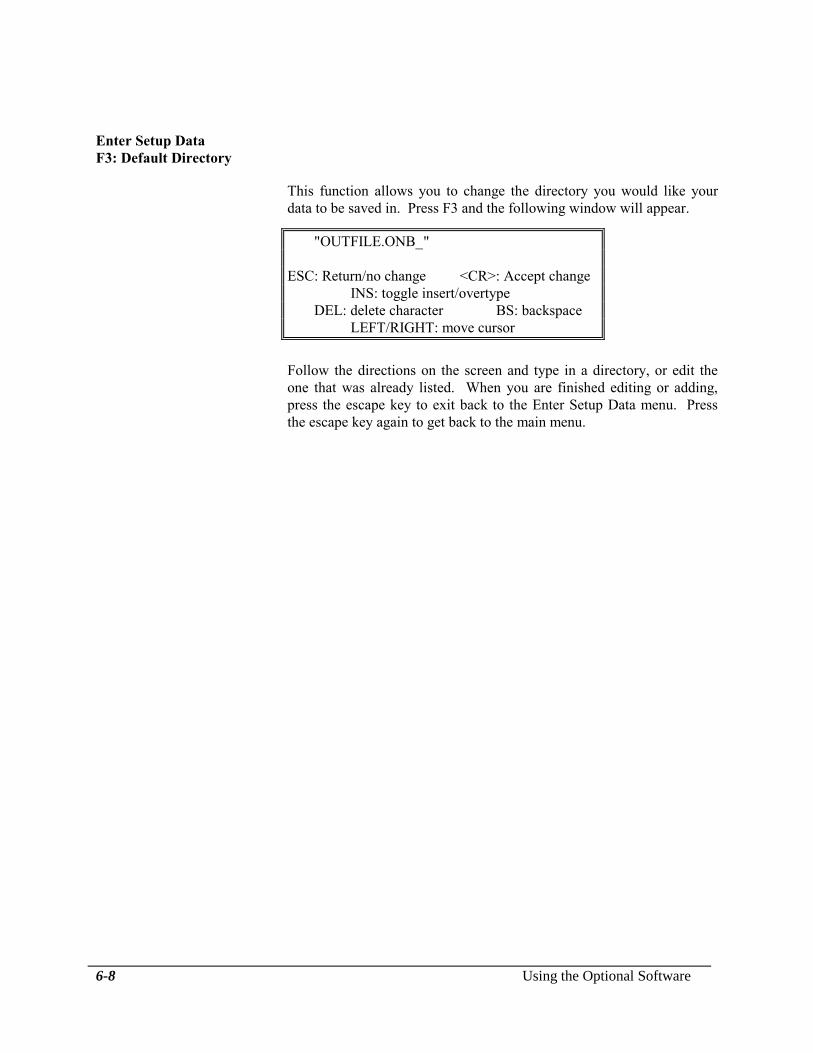
6-8 Using the Optional Software
Enter Setup Data
F3: Default Directory
This function allows you to change the directory you would like your
data to be saved in. Press F3 and the following window will appear.
"OUTFILE.ONB_ "
ESC: Return/no change <CR>: Accept change
INS: toggle insert/overtype
DEL: delete character BS: backspace
LEFT/RIGHT: move cursor
Follow the directions on the screen and type in a directory, or edit the
one that was already listed. When you are finished editing or adding,
press the escape key to exit back to the Enter Setup Data menu. Press
the escape key again to get back to the main menu.
Maintaining the System 7-1
Section 7
Maintaining the System
This section describes the maintenance procedures you should observe
to obtain maximum life and accuracy from the data card system. It also
includes some trouble-shooting hints should problems occur with the
system.
Data Recorder Care
The data recorder does not require periodic maintenance.
Follow these guidelines in caring for the data recorder.
Keep the data recorder warm and dry to extend its useful life. During
wet or cold weather, remove the unit from the aircraft, or cover it to
reduce the possibility of water absorption.
Avoid extreme temperature changes. Although the data recorder is
water resistant, highly variable conditions may cause moisture entry
because of a reduction of internal pressure.
If the data recorder battery needs changing, use the proper
replacement, as described in Replacing the Data Recorder Battery.
Do not open the data recorder. Opening the data
recorder voids its warranty. The battery is the only
user-replaceable part.
Cable and Connector Maintenance
Follow these guidelines for cable and connector maintenance.
Check cables and connectors periodically for signs of wear. Replace
cables that have worn through the foil shield.
Attempt to identify and correct the causes of cable wear including
bending, shearing, and sawing.
Cover and protect the connectors when not in use to prevent
corrosion and mechanical damage to the pins.

7-2 Maintaining the System
Troubleshooting
This topic lists problems you may encounter when using the Data Card
System, and describes possible solutions.
Power is on but the data
recorder display does not
show a readout. The unit
appears to be dead.
1. Use the CONTR key with the Up and Down keys to adjust the
display contrast. The Up key decreases the contrast, and the Down
key increases the contrast. If no response,
2. Check the fuse or circuit breaker between the positive battery wire
and the data recorder. Replace the fuse if it is faulty.
3. Check the entire power cable for damage, corrosion or a faulty
connection. Clean or replace wiring if problems are found.
4. If there is no response to these solutions, refer to the Appendix for
instructions for returning the unit to the factory.
Numbers appear on the
display but they do not
change with weight or
when a key is pressed.
This problem is caused by a momentary burst or lapse of electrical
power, causing a break in the flow of the program in the data recorder.
1. The problem can usually be reversed by shutting off the data
recorder power switch for several seconds.
2. As a long term solution, ensure that all electrical wiring is secure
and free of corrosion, and install an electrical filter.
Initializing Press and hold the Up and Down Keys while turning on the power to
the unit. Once the display is activated you may release the keys. The
display will tell that it is “Initializing” and instruct you to wait. This
process erases all operator installed data and re-enters factory defaults.

Installation Authorization 8-1
Section 8
Installation Authorization
The Date Card System installation is authorized by the Federal Aviation
Administration (FAA) for use with all Onboard Systems Electronic Load
Weigh Systems.
FAA Letter of Authorization

This page intentionally left blank.

Appendix A-1
Appendix
This appendix contains the following information for the Data Card
System.
Specifications
Ordering information
Limited warranty
Return instructions
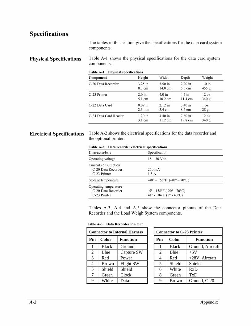
A-2 Appendix
Specifications
The tables in this section give the specifications for the data card system
components.
Physical Specifications Table A-1 shows the physical specifications for the data card system
components.
Table A-1 Physical specifications
Component Height Width Depth Weight
C-20 Data Recorder 3.25 in
8.3 cm
5.50 in
14.0 cm
2.20 in
5.6 cm
1.0 lb
455 g
C-23 Printer 2.0 in
5.1 cm
4.0 in
10.2 cm
4.5 in
11.4 cm
12 oz
340 g
C-22 Data Card 0.09 in
2.3 mm
2.12 in
5.4 cm
3.40 in
8.6 cm
1 oz
28 g
C-24 Data Card Reader 1.20 in
3.1 cm
4.40 in
11.2 cm
7.80 in
19.8 cm
12 oz
340 g
Electrical Specifications Table A-2 shows the electrical specifications for the data recorder and
the optional printer.
Table A-2 Data recorder electrical specifications
Characteristic Specification
Operating voltage 18 – 30 Vdc
Current consumption
C-20 Data Recorder
C-23 Printer
250 mA
1.5 A
Storage temperature -40° – 158°F (-40° – 70°C)
Operating temperature
C-20 Data Recorder
C-23 Printer
-5° - 158°F (-20° - 70°C)
41° - 104°F (5° - 40°C)
Tables A-3, A-4 and A-5 show the connector pinouts of the Data
Recorder and the Load Weigh System components.
Table A-3 Data Recorder Pin Out
Connector to Internal Harness Connector to C-23 Printer
Pin Color Function Pin Color Function
1 Black Ground 1 Black Ground, Aircraft
2 Blue Capture SW 2 Blue +5V
3 Red Power 4 Red +28V, Aircraft
4 Brown Flight SW 5 Shield Shield
5 Shield Shield 6 White RxD
7 Green Clock 8 Green TxD
9 White Data 9 Brown Ground, C-20

Appendix A-3
Table A-4 C-39 Indicator Pin Out
210-095-00 Indicator
Pin
Letter
Function
A + 28 VDC In
B - Load Cell Signal
C + Load Cell Signal
D + Load Cell Excitation
E Load Cell Common
F Analog Out Common
G + Analog Out
H Hook Open
J Data Recorder Clock
K Data Recorder Data
L Shield
M Back Light Common
N Back Light Source 28 VDC
P Aircraft Ground
R Not Used
Table A-5 Load Cell Pin Out
Pin
Letter
Wire Color
A Red
B Green
C White
D Black
E Shield

A-4 Appendix
Ordering Information
Order additional data card system components, accessories, and supplies
by quantity and the part number shown in Table A-6. All items can be
ordered separately.
Table A-6 Ordering information
Description Part number
Hardware components C-20 Data Recorder 210-048-01
C-23 Printer 210-100-00
C-22 Data Card, 8 Kb, 740 entries 475-006-00
C-22 Data Card, 32 Kb, 2,600 entries 475-007-00
C-24 Data Card Reader 210-050-00
Software components Software, IBM PC and 100%-compatibles 100-025-00
Accessories Data Card System Owner's Manual 120-024-02
Capture switch wire 270-019-00
Flight-time switch wire 270-022-00
AC adaptor for C-24 Data Card Reader 442-007-00
Supplies Roll paper for C-23 Printer 215-051-00
Cartridge ribbon for C-23 Printer 212-006-00
Battery for C-22 Data Card 470-003-00
Battery for C-20 Data Recorder clock 470-002-00

Appendix A-5
Limited Warranty
ONBOARD SYSTEMS Data Card System components are warranted to
be free from defects in workmanship and materials for a period of one
year from the date of purchase. The components are warranted to
function as intended when properly installed and used for their intended
purpose. Parts which prove to be defective are repaired or replaced free
of charge FOB factory at the manufacturer's option if the following
conditions have been met.
No repairs have been attempted by other than Onboard Systems
personnel.
The system or component is returned properly packaged, insured,
with transportation charges prepaid.
After examination, Onboard Systems personnel are satisfied that the
defects were not caused by abuse, and that the components were not
subjected to conditions that violate system specifications.
The following are specifically excluded from this warranty.
Software
Cables
This warranty covers only the original purchaser. In no event shall
Onboard Systems be liable for indirect, special, incidental or
consequential damage resulting from the use of this product, even if
Onboard Systems has been advised of the possibility of such damage.
Each user must satisfy himself that the system is suited to his needs and
is performing according to his requirements.
A-6 Appendix
Instructions for Returning Equipment to the Factory
If an Onboard Systems product must be returned to the factory for any reason (including returns, service, repairs, overhaul, etc) obtain an RMA number before shipping your return.
An RMA number is required for all equipment returns.
To obtain an RMA, please use one of the listed methods.
Contact Technical Support by phone or e-mail ([email protected]).
Generate an RMA number at our website: http://www.onboardsystems.com/rma.php
After you have obtained the RMA number, please be sure to:
Package the component carefully to ensure safe transit.
Write the RMA number on the outside of the box or on the mailing label.
Include the RMA number and reason for the return on your purchase or work order.
Include your name, address, phone and fax number and email (as applicable).
Return the components freight, cartage, insurance and customs prepaid to:
Onboard Systems 13915 NW 3rd Court Vancouver, Washington 98685 USA Phone: 360-546-3072