data brief - st33tphf2ei2c - flash-memory based device
TRANSCRIPT

VFQFPN32(5 × 5 mm)
TSSOP28(9.7 × 6.4 mm,
4.4 mm body width)
Features
TPM features
• Flash-memory-based Trusted Platform Module (TPM)• Supporting two modes exclusively with either the TPM 1.2 or the TPM 2.0
command set• Supporting dynamic switch from one mode to another and capability to lock one
mode irreversibly• For TPM 1.2, compliant with Trusted Computing Group (TCG) Trusted Platform
Module (TPM) Main specifications 1.2, Level 2, Revision 116 and TCG PC ClientSpecific TPM Interface Specifications 1.3
• For TPM 2.0, compliant with Trusted Computing Group (TCG) Trusted PlatformModule (TPM) Library specifications 2.0, Level 0, Revision 138 and TCG PCClient Specific TPM Platform Specifications 1.03
• Compliant with the Trusted Computing Group (TCG) Trusted Platform Module(TPM) I²C Interface Specification defined in PTP 1.03
• TPM firmware code can be upgraded thanks to a persistent Flash-memoryloader application to support new standard evolutions
• Common Criteria (CC) certification according to the TPM 1.2 and TPM 2.0protection profiles at EAL4+
• FIPS 140-2 level 1 certification for both modes and level 2 for mode TPM2.0• I²C support up to 400 kHz
Hardware features
• Arm® SecurCore® SC300™ 32-bit RISC core• Highly reliable Flash memory technology• Extended temperature range: −40 °C to 105 °C• ESD (electrostatic discharge) protection up to 4 kV (HBM)• 1.8 V or 3.3 V supply voltage range
Security features
• Active shield and environmental sensors• Memory protection unit (MPU) used to segregate TPM assets between TPM 1.2
and TPM 2.0 modes• Monitoring of environmental parameters (power and clock)• Hardware and software protection against fault injection• FIPS compliant RNG built on an SP800-90A compliant SHA256 DRBG and an
AIS-31 Class PTG2 compliant true random number generator (TRNG)• Cryptographic algorithms:
– RSA key generation (1024 or 2048 bits)– RSA signature and encryption
Product compliance
• TPM 1.2 and TPM 2.0 compliant with the respective TCG test suites
Product status link
ST33TPHF2EI2C
STSAFE-TPM
Flash-memory based device combining TPM 1.2 and TPM 2.0 with an I²C interface
ST33TPHF2EI2C
Data brief
DB3670 - Rev 2 - November 2019For further information contact your local STMicroelectronics sales office.
www.st.com

1 Description
The ST33TPHF2EI2C is a cost-effective and high-performance Trusted Platform Module (TPM) targeting PC,server platforms and embedded systems.This product supports two modes exclusively: TPM 1.2 mode and TPM 2.0 mode. In TPM 1.2 mode, the set ofTPM 1.2 commands is supported and only TPM 1.2 assets can be accessed. In TPM 2.0 mode, the set of TPM2.0 commands is supported and only TPM 2.0 assets can be accessed.In TPM 1.2 mode, the product implements the functions defined by the Trusted Computing Group(www.trustedcomputinggroup.org) in the TCG Trusted Platform Module Specifications version 1.2 Level 2Revision 116 [TPM1.2 P1 r116], [TPM1.2 P2 r116], [TPM1.2 P3 r116]), and is also based on the TCG PC Clientspecific TPM interface specifications 1.3 [TIS 1.30].In TPM 2.0 mode, the product implements the functions defined by the Trusted Computing Group(www.trustedcomputinggroup.org) in the TCG Trusted Platform Module Library Specifications version 2.0 Level 0Revision 138 ([TPM 2.0 P1 r138], [TPM 2.0 P2 r138], [TPM 2.0 P3 r138], [TPM 2.0 P4 r138]) and errata version1.4 [TPM 2.0 rev138 Err 1.4]. It is also based on the TCG PC client-specific TPM Platform specifications rev 1.03[PTP 2.0 r1.03] and [Errata sheet]. [TPM 2.0 PP] specifies the protection profile.The product also supports the ability to upgrade the TPM firmware thanks to a persistent application Flash loaderto support new standard evolutions.
1.1 Security certifications
This product is CC certified according to TPM 1.2 and TPM 2.0 at EAL4+.It obtained FIPS 140-2 level 1 certification for both modes and level 2 for mode TPM2.0.
1.2 Hardware features
The ST33TPHF2EI2C is based on a smartcard-class secure MCU that incorporates the most recent generation ofArm® processors for embedded secure systems. Its SecurCore® SC300™ 32-bit RISC core is built on theCortex® M3 core with additional security features to help to protect against advanced forms of attacks.The ST33TPHF2EI2C offers an Inter-Integrated Circuit (I²C) interface capable of supporting the TGC TPM I2Cspecification based on the TCG PC Client Specific TPM Interface Specification (TIS) version 1.3 in TPM 1.2 mode[TIS 1.30] and TCG PC Client TPM Profile in TPM 2.0 mode [PTP 2.0 r1.03] and [Errata sheet].The ST33TPHF2EI2C features hardware accelerators for advanced cryptographic functions. The AES peripheralprovides a secure AES (Advanced Encryption Standard) algorithm implementation, while the NESCRYPTcryptoprocessor efficiently supports the public key algorithms.The ST33TPHF2EI2C operates in the −25 to +85 °C commercial temperature range (see Section 8 Orderinginformation) with a supply and I/O voltage of 1.8 V or 3.3 V.It operates in the −40 to +105 °C commercial temperature range (see Section 8 Ordering information) with asupply and I/O voltage of 3.3 V.In order to meet environmental requirements, ST offers these devices in different grades of ECOPACK®
packages, depending on their level of environmental compliance. ECOPACK® specifications, grade definitionsand product status are available at: www.st.com. ECOPACK® is an ST trademark.
Note: Arm is a registered trademark of Arm Limited (or its subsidiaries) in the US and/or elsewhere.
ST33TPHF2EI2C Description
DB3670 - Rev 2 page 2/26
2 Data brief scope
2.1 ST33TPHF2EI2C products
This document covers the functionality of firmware 49.41 (73.65 in decimal) preloaded on ST TPM hardware withmarking: PEAHC2 with “V2” in the J marking area.The firmware version is retrieved with the TPM_GetCapability or TPM2_GetCapability command. Thefirmware digest, which is a cryptographic footprint, also uniquely identifies the firmware loaded on the product.The information to order the supporting platforms is provided in Section 8 Ordering information.
2.2 Firmware image
The ST33TPHF2EI2C datasheet describes the functionality of the firmware image 49.41 (73.65 in decimal)loaded on ST TPM hardware with markings:• P68HAHB7• P68HAHB8• PEAHC2 (J marking area is empty)
The information to order the supporting platforms is provided in Section 8 Ordering information.See Section 9 Firmware image overview for an overview of the available firmware images.
ST33TPHF2EI2C Data brief scope
DB3670 - Rev 2 page 3/26

3 Pin and signal description
Figure 1. TSSOP28 pinout
TSSOP287PP/GPIO[A]8
NiC
9NiC10VPS11GND121314NiC
NiC
GPIO[B]
NiCNiC
NiC
123456
NiCNiC
NiC
NiCNiC
NiCSCLSDA
2221201918171615
282726252423
NiCNiCNiC
GPIO[C]GPIO[D]
NiC
NiC
IRQ
RESET
Figure 2. VQFN32 pinout
VQFN32
1VPS2NiC3NiC4PP/GPIO[A]5NiC6NiC7NiC8NiC
32
NiC
31
NiC
30
SCL
29
SDA
28
GPI
O[C
]
27
GPI
O[D
]
26
NiC
25
NiC
NiCNiCNiCNiCNiCNiCIRQRESET
2423222120191817
9 10 11 12 13 14 15 16
GN
DN
iCN
iCN
iCG
PIO
[B]
NiC
NiC
NiC
Table 1. Pin descriptions
Signal Type Description
VPS Input Power supply. This pin must be connected to 1.8 V or 3.3 V DC power rail on the motherboard.
GND Input GND has to be connected to the main motherboard ground.
SDA Bidir I2C serial data (open drain with no weak pull-up resistor)
SCL Input I2C serial clock (open drain with no weak pull-up resistor)
IRQ Output IRQ used by the TPM to generate an interrupt
ST33TPHF2EI2C Pin and signal description
DB3670 - Rev 2 page 4/26

Signal Type Description
RESET Input Reset used to re-initialize the device
GPIO[A..D] Input/ output General-purpose input/output. Defaults to low.
PP Input Physical Presence, active high, internal pull-down. Used to indicate Physical Presence to theTPM.
NiC - Not internally connected: not connected to the die. May be left unconnected but has no impacton the TPM if connected.
ST33TPHF2EI2C Pin and signal description
DB3670 - Rev 2 page 5/26

4 Integration guidance
4.1 Typical hardware implementation
The Physical Presence (PP) pin should be connected if platform implementation (at boot level) uses a hardwarephysical presence function.
Figure 3. Typical hardware implementation (TSSOP28 package)
NiC24
NiC23
NiC22
NiC21
IRQ#20
NiC19
NiC18
NiC17
RESET#16
GPIO[B]15
NiC14
NiC13
NiC4
NiC5
GND11
NiC12
VPS10
NiC9
NiC8
PP/GPIO[A]7
NiC6
NiC3
SCL2
SDA1
NiC25
NiC26
GPIO[D]27
GPIO[C]28
VPS
100 nF 10 µF
GND
IRQ#
PP/GPIO[A]
RESET#
SDA
SDL
GND
GPIO[C]
GPIO[D]
GPIO[B]
2.2 kΩ
2.2 kΩ
ST33TPHF2EI2C Integration guidance
DB3670 - Rev 2 page 6/26

4.2 Power supply filtering
As mentioned in Section 3 Pin and signal description, the power supply of the circuit must be filtered using thecircuit shown in the figure below.
Figure 4. Mandatory filtering capacitors on VPS
TPM
Host device
RESET#
VPS
GND
100 nF10 µF
-
IRQ#
SCLSDA
+
1. 10 µF and 100 nF are recommended values. The minimum required capacitor value is 2.1 µF (2 µF inparallel with 100 nF).
ST33TPHF2EI2C Power supply filtering
DB3670 - Rev 2 page 7/26

5 Package information
In order to meet environmental requirements, ST offers these devices in different grades of ECOPACK packages,depending on their level of environmental compliance. ECOPACK specifications, grade definitions and productstatus are available at: www.st.com. ECOPACK is an ST trademark.
5.1 TSSOP28 package information
TSSOP28 is a 28-pin, 9.7 × 6.4 mm, 4.4 mm body width, 0.65 mm pitch, thin shrink small outline package.Unless otherwise specified, general tolerance is ± 0.1 mm.
Figure 5. TSSOP28 - outline
c
L
k
A1
aaa
A2A
eb
1
28
14
15
D
EE1
L1
1. Drawing is not to scale.
Table 2. TSSOP28 - mechanical data
Symbolmillimeters inches (1)
Min. Typ. Max. Min. Typ. Max.
A - - 1.200 - - 0.0472
A1 0.050 - 0.150 0.0020 - 0.0059
A2 0.800 1.000 1.050 0.0315 0.0394 0.0413
b 0.190 - 0.300 0.0075 - 0.0118
c 0.090 - 0.200 0.0035 - 0.0079
D 9.600 9.700 9.800 0.3780 0.3819 0.3858
E 6.200 6.400 6.600 0.2441 0.2520 0.2598
E1 4.300 4.400 4.500 0.1693 0.1732 0.1772
e - 0.650 - - 0.0256 -
L 0.450 0.600 0.750 0.0177 0.0236 0.0295
L1 - 1.000 - - 0.0394 -
ST33TPHF2EI2C Package information
DB3670 - Rev 2 page 8/26

Symbolmillimeters inches (1)
Min. Typ. Max. Min. Typ. Max.
k 0° - 8° 0° - 8°
aaa - - 0.100 - - 0.0039
1. Values in inches are converted from mm and rounded to 4 decimal digits.
Figure 6. TSSOP28 - recommended footprint
4.46.4
0.3
0.65
1.0
8.75
1 14
28 15
1. All dimensions are in millimeters.
ST33TPHF2EI2C TSSOP28 package information
DB3670 - Rev 2 page 9/26

5.2 VFQFPN32 package information
VFQFPN32 is a 32-lead, 5 × 5 mm, 0.5 mm pitch, very thin fine pitch quad flat pack no-lead package.
Figure 7. VFQFPN32 - outline
Seating plane
ddd CC
A3 A1
A
D
e
9 16
17
24
32Pin # 1 IDR = 0.30
8
E
L
L
D2
1
bE2
Bottom view
1. Drawing is not to scale.
Table 3. VFQFPN32 - mechanical data
Symbolmillimeters inches (1)
Min. Typ. Max. Min. Typ. Max.
A 0.800 0.900 1.000 0.0315 0.0354 0.0394
A1 0.000 0.020 0.050 0.0000 0.0008 0.0020
A3 - 0.200 - - 0.0079 -
b 0.180 0.250 0.300 0.0071 0.0098 0.0118
D 4.850 5.000 5.150 0.1909 0.1969 0.2028
D2 3.500 3.600 3.700 0.1378 0.1417 0.1457
ST33TPHF2EI2C VFQFPN32 package information
DB3670 - Rev 2 page 10/26
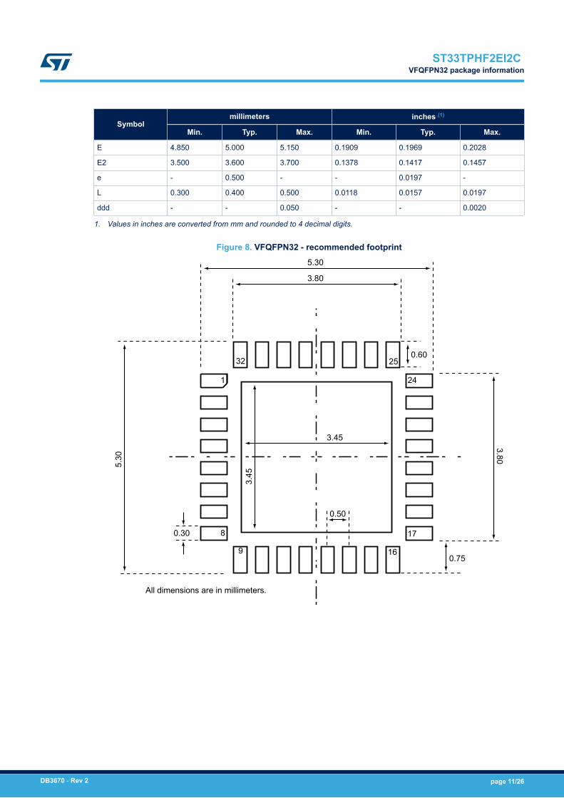
Symbolmillimeters inches (1)
Min. Typ. Max. Min. Typ. Max.
E 4.850 5.000 5.150 0.1909 0.1969 0.2028
E2 3.500 3.600 3.700 0.1378 0.1417 0.1457
e - 0.500 - - 0.0197 -
L 0.300 0.400 0.500 0.0118 0.0157 0.0197
ddd - - 0.050 - - 0.0020
1. Values in inches are converted from mm and rounded to 4 decimal digits.
Figure 8. VFQFPN32 - recommended footprint
All dimensions are in millimeters.
1
25
24
17
16
8
9
32
5.30
3.80
5.30
3.80
0.60
0.75
3.45
3.45
0.50
0.30
ST33TPHF2EI2C VFQFPN32 package information
DB3670 - Rev 2 page 11/26

5.3 Thermal characteristics of packages
The table below provides the thermal characteristics of the TSSOP28 and VFQFPN32 packages.
Table 4. Thermal characteristics
Parameter Symbol Value
Recommended operating temperature range
Ambient temperature TA −40 to 105 °C
Case temperature TC -
Junction temperature TJ −43 to 108 °C
Absolute maximum junction temperature - 125 °C
Maximum power dissipation - 63 mW
Theta-JA, -JB and -JC
Junction to ambient thermal resistance θJA 35.8 at 0 lfpm (1)
Junction to case thermal resistance θJC 1.48 at 0 lfpm(1)
Junction to board thermal resistance θJB 13.9 at 0 lfpm(1)
1. Linear feet per minute.
ST33TPHF2EI2C Thermal characteristics of packages
DB3670 - Rev 2 page 12/26

6 Delivery packing
Surface-mount packages can be supplied with tape and reel packing. The reels have a 13" typical diameter.Reels are in plastic, either anti-static or conductive, with a black conductive cavity tape. The cover tape istransparent anti-static or conductive.The devices are positioned in the cavities with the identifying pin (normally Pin “1”) on the same side as thesprocket holes in the tape.The STMicroelectronics tape and reel specifications are compliant to the EIA 481-A standard specification.
Table 5. Packages on tape and reel
Package Description Tape width Tape pitch Reel diameter Quantity per reel
TSSOP 28 Thin shrink small outline package 16 mm 8 mm 13 in. 2500
VFQFPN 32 Very thin fine pitch quad flat pack no-lead package 12 mm 8 mm 13 in. 3000
Figure 9. Reel diagram
A
D
B
C
N
T
G
Table 6. Reel dimensions
Reel size Tape width A Max. B Min. C D Min. G Max. N Min. T Max. Unit
13”16
330 1.5 13 ±0.2 20.216.4 +2/–0
10022.4
mm12 12.6 18.4
ST33TPHF2EI2C Delivery packing
DB3670 - Rev 2 page 13/26
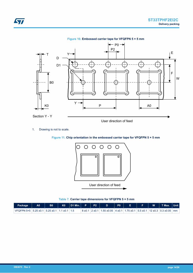
Figure 10. Embossed carrier tape for VFQFPN 5 × 5 mm
T
B0
K0
D
D1
Y
P2P0
Y
P A0
E
WF
Section Y - YUser direction of feed
1. Drawing is not to scale.
Figure 11. Chip orientation in the embossed carrier tape for VFQFPN 5 × 5 mm
User direction of feed
Table 7. Carrier tape dimensions for VFQFPN 5 × 5 mm
Package A0 B0 K0 D1 Min. P P2 D P0 E F W T Max. Unit
VFQFPN 5×5 5.25 ±0.1 5.25 ±0.1 1.1 ±0.1 1.5 8 ±0.1 2 ±0.1 1.55 ±0.05 4 ±0.1 1.75 ±0.1 5.5 ±0.1 12 ±0.3 0.3 ±0.05 mm
ST33TPHF2EI2C Delivery packing
DB3670 - Rev 2 page 14/26

Figure 12. Embossed carrier tape for TSSOP28 4.4 mm body width
W
TK
Bo
DP2
Po
B1
Ao
Bo
P
F
E
D1
User direction of feed
Ko
TopCoverTape
1. Drawing is not to scale.
Figure 13. Chip orientation in the embossed carrier tape for TSSOP28 4.4 mm body width
Typical
User direction of feed
Table 8. Carrier tape constant dimensions for TSSOP 4.4 mm body width
Tape size Ao, Bo, Ko (1) D E Po T Max. Unit
16 mm See note. 1.5 +0.1 / −0 1.75 ±0.1 4 ±0.1 0.4 mm
1. Ao, Bo, Ko, are determined by components sizes. The clearance between the component and the cavitymust be within 0.05 mm (Min.) to 0.90 mm (Max.)
ST33TPHF2EI2C Delivery packing
DB3670 - Rev 2 page 15/26

7 Package marking information
Figure 14. TSSOP28 device package marking area and Figure 15. VQFN32 device package marking areaillustrate the typical markings of the TSSOP28 and the VQFN32 device packages, respectively.
Figure 14. TSSOP28 device package marking area
A
B C D FE
HJGa
A: Marking areaB: Assembly plantC: BE sequenceD: Diffusion plantE: Assembly yearF: Assembly weekG: Ecopack levelH: ST logoJ: Marking area - 2 digitsa: Dot
Figure 15. VQFN32 device package marking area
A
B C D
E F G
IJH
K
A: Marking area
B: Assembly plant
C: BE sequence
D: Diffusion plant
E: Country of origin
F: Assembly year
G: Assembly week
H: Ecopack
I: ST logo
J: Marking area - 2 digits
K: Dot
For both packages, the 8-digit ‘A’ marking area is equal to “P68XYZZZ” with:• X = E• Y = Hardware revision• ZZZ = Firmware revision
For both packages, the 2-digit ‘J’ marking area is equal to V2.
ST33TPHF2EI2C Package marking information
DB3670 - Rev 2 page 16/26

8 Ordering information
Table 9. Ordering information for supporting firmware 49.41 preloaded in factory
Ordering code
Default
TPM Library &
Firmware version
Operatingtemperature
rangeMaximum I2C
clock frequency PackageMarking
(A area)
Marking
(J area)Productstatus
ST33HTPH2E28AHC2 TPM 2.0 active
0x00 0x49 0x00 0x41 (73.65)−40 °C to+105 °C 400 kHz
TSSOP28PEAHC2 V2 Active
ST33HTPH2E32AHC2 VQFN32
Table 10. Ordering information for products supporting firmware 49.41 loading
Ordering codeDefault TPM library
& firmware version
Default TPM library
& firmware version
after field upgrade
operation
Operating
temperature
range
Maximum
I²C clock
frequency
PackageMarking
(area A)
Marking
(area J)Productstatus
ST33HTPH2E28AHB8 TPM 1.2 active
0x00 0x49 0x00 0x05
(73.05)
TPM 1.2 active
0x00 0x49 0x00 0x41
(73.65)
−40 °C to +105 °C 400 kHz
TSSOP28
P68HAHB8 -
Notrecommendedfor newdesign(NRND)
ST33HTPH2E32AHB8 VQFN32
ST33HTPH2E28AHB7 TPM 2.0 active
0x00 0x49 0x00 0x05
(73.05)
TPM 2.0 active
0x00 0x49 0x00 0x41
(73.65)
−40 °C to +105 °C 400 kHz
TSSOP28
P68HAHB7 -
Notrecommendedfor newdesign(NRND)
ST33HTPH2E32AHB7 VQFN32
ST33HTPH2E28AHC2(1) TPM 2.0 active
0x00 0x49 0x00 0x09
(73.09)
TPM 2.0 active
0x00 0x49 0x00 0x41
(73.65)
−40 °C to +105 °C 400 kHz
TSSOP28
PEAHC2 - ObsoleteST33HTPH2E32AHC2(1) VQFN32
1. These ordering codes are exclusively available with preloaded 0x00 0x49 0x00 0x41 firmware. Parts with preloaded 0x00 0x49 0x00 0x09 firmwareare no more available for order.
DB
3670 - Rev 2
page 17/26
ST33TPHF2EI2C
O
rdering information

9 Firmware image overview
Table 11. Firmware image overview for the ST33TPHF2EI2C products
Firmware version Firmware version (TPM capability) TPM 2.0 libraryrevision Product status
73.05 0x00 0x49 0x00 0x05 1.16 NRND (not recommended for new design)
73.21 0x00 0x49 0x00 0x15 1.16 Active
73.09 0x00 0x49 0x00 0x09 1.38 NRND (not recommended for new design)
73.65 0x00 0x49 0x00 0x41 1.38 Active
Table 12. Commercial product supporting the update with firmware image version 73.21xx = 28 for products delivered in TSSOP28, and 32 for products delivered in QFN32 packages.
Commercial products Firmware preloaded in factory TPM2_Clear required before firmware update
ST33HTPH2ExxAHB7 73.05
0x00 0x49 0x00 0x05No
ST33HTPH2ExxAHB8
Table 13. Commercial product supporting the update with firmware image version 73.65xx = 28 for products delivered in TSSOP28, and 32 for products delivered in QFN32 packages.
Commercial products Firmware preloaded in factory TPM2_Clear required before firmware update
ST33HTPH2ExxAHB7 73.05
0x00 0x49 0x00 0x05Yes
ST33HTPH2ExxAHB8
ST33HTPH2ExxAHC2 73.090x00 0x49 0x00 0x09 No
ST33TPHF2EI2C Firmware image overview
DB3670 - Rev 2 page 18/26

10 Support and information
Additional information regarding ST TPM devices can be obtained from the www.st.com website.For any specific support information you can contact STMicroelectronics through the following e-mail:[email protected].
ST33TPHF2EI2C Support and information
DB3670 - Rev 2 page 19/26

11 Terms and abbreviations
Table 14. List of abbreviations
Term Meaning
AES Advanced Encryption Standard
CC Common Criteria
DAM Dictionary attack mitigation mechanism
Data byte Byte from the TPM command or answer or register value.
DES Data Encryption Standard
EC Elliptic curve
EK Endorsement key
FIPS Federal Information Processing Standard
GPIO General-purpose I/O
HMAC Keyed-Hashing for Message Authentication
I2C Inter IC interface (Philips protocol)
NIST National Institute of Standards and Technology
NV Non-volatile (memory)
OEM Original equipment manufacturer
OIAP Object-Independent Authorization Protocol
OSAP Object Specific Authorization Protocol
PCR Platform Configuration register
RSA Rivest Shamir Adelman
RTM Root of trust for measurement
RTR Root of trust for reporting
SHA Secure Hash algorithm
SRK Storage root key
TCG Trusted Computed Group
TIS TPM interface specification
TPM Trusted Platform Module
TPME TPM manufacturer
Transaction bytes All bytes from a TPM command or TPM answer.
TSS TPM software stack
ST33TPHF2EI2C Terms and abbreviations
DB3670 - Rev 2 page 20/26

12 Referenced documents
The following materials are to be used in conjunction with or are referenced by this document.
[TPM 1.2 P1 r116] TPM Main, Part 1, Design principles, Version 1.2 Level 2, rev 116, TCG
[TPM 1.2 P2 r116] TPM Main, Part 2, TPM Structures, Version 1.2 Level 2, revision 116, TCG
[TPM 1.2 P3 r116] TPM Main, Part 3, Commands, Version 1.2 Level 2, revision 116, TCG
[TIS 1.30] TCG PC Client Specific TPM Interface Specification (TIS) – Version 1.3
[TPM 2.0 P1 r138] TPM Library, Part 1, Architecture, Family 2.0, rev 1.38, TCG
[TPM 2.0 P2 r138] TPM Library, Part 2, Structures, Family 2.0, rev 1.38, TCG
[TPM 2.0 P3 r138] TPM Library, Part 3, Commands, Family 2.0, rev 1.38, TCG
[TPM 2.0 P4 r138] TPM Library, Part 4, Supporting routines, Family 2.0, rev 1.38, TCG
[TPM 2.0 rev138 Err 1.4] Errata 1.4 January 8, 2018 for TCG TPM library version 2.0 revision 1.38 September, 29 2016.
[PTP 2.0 r1.03] TCG PC Client Specific Platform TPM Specification (PTP) – Version 2.0 Revision 1.03
[PKCS#1] PKCS#1: v2.1 RSA Cryptography Standard, RSA Laboratories
[AN2639] Application note, Soldering recommendations and package information for Lead-freeECOPACK® microcontrollers, STMicroelectronics
[Errata sheet] Errata Version 1.1 TCG PC Client Specific Platform TPM Profile for TPM 2.0
[PC Client BIOS] TCG PC Client Specific Implementation Specification for Conventional BIOS – Version 1.2Final – Revision 1.00 – July 13, 2005.
[TCG EK Cre Profile TPM2.0]
TCG EK credential profile for TPM Family 2.0 Level 0. Specification Version 2.0 Revision 14,November 4, 2014, TCG.
[TPM 2.0 PP] Protection Profile PC Client Specific TPM, Family 2.0 Level 0 revision 1.38 (1.0), TCG.
ST33TPHF2EI2C Referenced documents
DB3670 - Rev 2 page 21/26

Revision history
Table 15. Document revision history
Date Revision Changes
15-Jun-2015 0.1 Initial release.
12-Jul-2018 1
Updated for firmware 49.9:• Updated Features and Section 1 Description.• Updated Section 7 Package marking information.• Updated Section 12 Referenced documents.• Updated Section 8 Ordering information.
Updated operating temperature range.
Updated certifications.
Added Section 2 Data brief scope and Section 4 Integration guidance.
Added Section 5.3 Thermal characteristics of packages.
Added Figure 11. Chip orientation in the embossed carrier tape for VFQFPN 5 × 5 mm andFigure 13. Chip orientation in the embossed carrier tape for TSSOP28 4.4 mm body width.
19-Nov-2019 2
Updated errata version number (Section 1 Description and Section 12 Referenced documents).Updated Section 2.1 ST33TPHF2EI2C products.
Added Section 2.2 Firmware image.
Removed Section New features.
Small text changes:• TSSOP28 description (first page),• Section 5.1 TSSOP28 package information,• Section 5.2 VFQFPN32 package information.
Updated Section 5.3 Thermal characteristics of packages, Section 7 Package markinginformation and Section 8 Ordering information.
Added Section 9 Firmware image overview.
ST33TPHF2EI2C
DB3670 - Rev 2 page 22/26

Contents
1 Description . . . . . . . . . . . . . . . . . . . . . . . . . . . . . . . . . . . . . . . . . . . . . . . . . . . . . . . . . . . . . . . . . . . . . . . .2
1.1 Security certifications . . . . . . . . . . . . . . . . . . . . . . . . . . . . . . . . . . . . . . . . . . . . . . . . . . . . . . . . . . . 2
1.2 Hardware features. . . . . . . . . . . . . . . . . . . . . . . . . . . . . . . . . . . . . . . . . . . . . . . . . . . . . . . . . . . . . . 2
2 Data brief scope . . . . . . . . . . . . . . . . . . . . . . . . . . . . . . . . . . . . . . . . . . . . . . . . . . . . . . . . . . . . . . . . . . .3
2.1 ST33TPHF2EI2C products . . . . . . . . . . . . . . . . . . . . . . . . . . . . . . . . . . . . . . . . . . . . . . . . . . . . . . 3
2.2 Firmware image. . . . . . . . . . . . . . . . . . . . . . . . . . . . . . . . . . . . . . . . . . . . . . . . . . . . . . . . . . . . . . . . 3
3 Pin and signal description . . . . . . . . . . . . . . . . . . . . . . . . . . . . . . . . . . . . . . . . . . . . . . . . . . . . . . . . .4
4 Integration guidance. . . . . . . . . . . . . . . . . . . . . . . . . . . . . . . . . . . . . . . . . . . . . . . . . . . . . . . . . . . . . . .6
4.1 Typical hardware implementation . . . . . . . . . . . . . . . . . . . . . . . . . . . . . . . . . . . . . . . . . . . . . . . . . 6
4.2 Power supply filtering . . . . . . . . . . . . . . . . . . . . . . . . . . . . . . . . . . . . . . . . . . . . . . . . . . . . . . . . . . . 7
5 Package information. . . . . . . . . . . . . . . . . . . . . . . . . . . . . . . . . . . . . . . . . . . . . . . . . . . . . . . . . . . . . . .8
5.1 28-pin thin shrink small outline package information . . . . . . . . . . . . . . . . . . . . . . . . . . . . . . . . . 8
5.2 32-lead very thin fine pitch quad flat pack no-lead (VFQFPN) package information. . . . . . . . 9
5.3 Thermal characteristics of packages . . . . . . . . . . . . . . . . . . . . . . . . . . . . . . . . . . . . . . . . . . . . . 12
6 Delivery packing. . . . . . . . . . . . . . . . . . . . . . . . . . . . . . . . . . . . . . . . . . . . . . . . . . . . . . . . . . . . . . . . . .13
7 Package marking information . . . . . . . . . . . . . . . . . . . . . . . . . . . . . . . . . . . . . . . . . . . . . . . . . . . . .16
8 Ordering information . . . . . . . . . . . . . . . . . . . . . . . . . . . . . . . . . . . . . . . . . . . . . . . . . . . . . . . . . . . . .17
9 Firmware image overview. . . . . . . . . . . . . . . . . . . . . . . . . . . . . . . . . . . . . . . . . . . . . . . . . . . . . . . . .18
10 Support and information . . . . . . . . . . . . . . . . . . . . . . . . . . . . . . . . . . . . . . . . . . . . . . . . . . . . . . . . . .19
11 Terms and abbreviations. . . . . . . . . . . . . . . . . . . . . . . . . . . . . . . . . . . . . . . . . . . . . . . . . . . . . . . . . .20
12 Referenced documents . . . . . . . . . . . . . . . . . . . . . . . . . . . . . . . . . . . . . . . . . . . . . . . . . . . . . . . . . . .21
Revision history . . . . . . . . . . . . . . . . . . . . . . . . . . . . . . . . . . . . . . . . . . . . . . . . . . . . . . . . . . . . . . . . . . . . . . .22
Contents . . . . . . . . . . . . . . . . . . . . . . . . . . . . . . . . . . . . . . . . . . . . . . . . . . . . . . . . . . . . . . . . . . . . . . . . . . . . . .23
List of tables . . . . . . . . . . . . . . . . . . . . . . . . . . . . . . . . . . . . . . . . . . . . . . . . . . . . . . . . . . . . . . . . . . . . . . . . . .24
List of figures. . . . . . . . . . . . . . . . . . . . . . . . . . . . . . . . . . . . . . . . . . . . . . . . . . . . . . . . . . . . . . . . . . . . . . . . . .25
ST33TPHF2EI2C Contents
DB3670 - Rev 2 page 23/26

List of tablesTable 1. Pin descriptions . . . . . . . . . . . . . . . . . . . . . . . . . . . . . . . . . . . . . . . . . . . . . . . . . . . . . . . . . . . . . . . . . . . . . 4Table 2. TSSOP28 - mechanical data . . . . . . . . . . . . . . . . . . . . . . . . . . . . . . . . . . . . . . . . . . . . . . . . . . . . . . . . . . . . 8Table 3. VFQFPN32 - mechanical data . . . . . . . . . . . . . . . . . . . . . . . . . . . . . . . . . . . . . . . . . . . . . . . . . . . . . . . . . . 10Table 4. Thermal characteristics. . . . . . . . . . . . . . . . . . . . . . . . . . . . . . . . . . . . . . . . . . . . . . . . . . . . . . . . . . . . . . . 12Table 5. Packages on tape and reel . . . . . . . . . . . . . . . . . . . . . . . . . . . . . . . . . . . . . . . . . . . . . . . . . . . . . . . . . . . . 13Table 6. Reel dimensions . . . . . . . . . . . . . . . . . . . . . . . . . . . . . . . . . . . . . . . . . . . . . . . . . . . . . . . . . . . . . . . . . . . 13Table 7. Carrier tape dimensions for VFQFPN 5 × 5 mm . . . . . . . . . . . . . . . . . . . . . . . . . . . . . . . . . . . . . . . . . . . . . . 14Table 8. Carrier tape constant dimensions for TSSOP 4.4 mm body width . . . . . . . . . . . . . . . . . . . . . . . . . . . . . . . . . . 15Table 9. Ordering information for supporting firmware 49.41 preloaded in factory . . . . . . . . . . . . . . . . . . . . . . . . . . . . . 17Table 10. Ordering information for products supporting firmware 49.41 loading . . . . . . . . . . . . . . . . . . . . . . . . . . . . . . . 17Table 11. Firmware image overview for the ST33TPHF2EI2C products. . . . . . . . . . . . . . . . . . . . . . . . . . . . . . . . . . . . . 18Table 12. Commercial product supporting the update with firmware image version 73.21 . . . . . . . . . . . . . . . . . . . . . . . . 18Table 13. Commercial product supporting the update with firmware image version 73.65 . . . . . . . . . . . . . . . . . . . . . . . . 18Table 14. List of abbreviations . . . . . . . . . . . . . . . . . . . . . . . . . . . . . . . . . . . . . . . . . . . . . . . . . . . . . . . . . . . . . . . . . 20Table 15. Document revision history . . . . . . . . . . . . . . . . . . . . . . . . . . . . . . . . . . . . . . . . . . . . . . . . . . . . . . . . . . . . . 22
ST33TPHF2EI2C List of tables
DB3670 - Rev 2 page 24/26

List of figuresFigure 1. TSSOP28 pinout. . . . . . . . . . . . . . . . . . . . . . . . . . . . . . . . . . . . . . . . . . . . . . . . . . . . . . . . . . . . . . . . . . . 4Figure 2. VQFN32 pinout. . . . . . . . . . . . . . . . . . . . . . . . . . . . . . . . . . . . . . . . . . . . . . . . . . . . . . . . . . . . . . . . . . . . 4Figure 3. Typical hardware implementation (TSSOP28 package) . . . . . . . . . . . . . . . . . . . . . . . . . . . . . . . . . . . . . . . . 6Figure 4. Mandatory filtering capacitors on VPS . . . . . . . . . . . . . . . . . . . . . . . . . . . . . . . . . . . . . . . . . . . . . . . . . . . . 7Figure 5. TSSOP28 - outline . . . . . . . . . . . . . . . . . . . . . . . . . . . . . . . . . . . . . . . . . . . . . . . . . . . . . . . . . . . . . . . . . 8Figure 6. TSSOP28 - recommended footprint. . . . . . . . . . . . . . . . . . . . . . . . . . . . . . . . . . . . . . . . . . . . . . . . . . . . . . 9Figure 7. VFQFPN32 - outline . . . . . . . . . . . . . . . . . . . . . . . . . . . . . . . . . . . . . . . . . . . . . . . . . . . . . . . . . . . . . . . 10Figure 8. VFQFPN32 - recommended footprint. . . . . . . . . . . . . . . . . . . . . . . . . . . . . . . . . . . . . . . . . . . . . . . . . . . . 11Figure 9. Reel diagram . . . . . . . . . . . . . . . . . . . . . . . . . . . . . . . . . . . . . . . . . . . . . . . . . . . . . . . . . . . . . . . . . . . . 13Figure 10. Embossed carrier tape for VFQFPN 5 × 5 mm . . . . . . . . . . . . . . . . . . . . . . . . . . . . . . . . . . . . . . . . . . . . . 14Figure 11. Chip orientation in the embossed carrier tape for VFQFPN 5 × 5 mm. . . . . . . . . . . . . . . . . . . . . . . . . . . . . . 14Figure 12. Embossed carrier tape for TSSOP28 4.4 mm body width . . . . . . . . . . . . . . . . . . . . . . . . . . . . . . . . . . . . . . 15Figure 13. Chip orientation in the embossed carrier tape for TSSOP28 4.4 mm body width . . . . . . . . . . . . . . . . . . . . . . 15Figure 14. TSSOP28 device package marking area . . . . . . . . . . . . . . . . . . . . . . . . . . . . . . . . . . . . . . . . . . . . . . . . . 16Figure 15. VQFN32 device package marking area . . . . . . . . . . . . . . . . . . . . . . . . . . . . . . . . . . . . . . . . . . . . . . . . . . 16
ST33TPHF2EI2C List of figures
DB3670 - Rev 2 page 25/26

IMPORTANT NOTICE – PLEASE READ CAREFULLY
STMicroelectronics NV and its subsidiaries (“ST”) reserve the right to make changes, corrections, enhancements, modifications, and improvements to STproducts and/or to this document at any time without notice. Purchasers should obtain the latest relevant information on ST products before placing orders. STproducts are sold pursuant to ST’s terms and conditions of sale in place at the time of order acknowledgement.
Purchasers are solely responsible for the choice, selection, and use of ST products and ST assumes no liability for application assistance or the design ofPurchasers’ products.
No license, express or implied, to any intellectual property right is granted by ST herein.
Resale of ST products with provisions different from the information set forth herein shall void any warranty granted by ST for such product.
ST and the ST logo are trademarks of ST. For additional information about ST trademarks, please refer to www.st.com/trademarks. All other product or servicenames are the property of their respective owners.
Information in this document supersedes and replaces information previously supplied in any prior versions of this document.
© 2019 STMicroelectronics – All rights reserved
ST33TPHF2EI2C
DB3670 - Rev 2 page 26/26