danaher profile rail linear guides - pretekdanaher motion - helping you build a better machine,...
TRANSCRIPT

Profile Rail Linear Guides500 Series Ball Profile Rail500 Series Roller Profile RailAccuMiniMicroGuideT-Series

Danaher Motion - Helping you build a better machine, faster Danaher Corporation combined over 30 industry-leading brands such as Kollmorgen, Thomson, Dover, Pacific Scientific, Portescap, Neff, Seidel and Bautz to establish a customer-focused motion control manufacturing company called Danaher Motion. We offer this powerful set of integrated motion control technologies under the Danaher Motion and Thomson brand names. We are a $1B+ global motion control leader, unique in our ability to marshal decades of application experi-ence and technical innovation to help you build better machines, faster.
Danaher Motion defines high standards of quality, innovation and technology. We enable improved machine performance and reliability while controlling costs. Our global manufacturing footprint, rapid customization and prototyping capa-bilities drive quick lead times. Unmatched application experience and design expertise empowers you to commission machines faster.
Consider your options in today’s market for a motion control partner. Select Danaher Motion and join a team with over 6000 employees, over 60 years of application experience and 2000+ distributor locations around the globe. Danaher Motion serves industries as diverse as semiconductor, aerospace and defense, electric vehicle systems, packaging, printing, medical and robotics. We offer an unparalleled depth and breadth of motion control product solutions through a worldwide service and support infrastructure, field service engineers and support teams available when and where you need them.
The Danaher Business System - Building sustainable competitive advantage into your business
The Danaher Business System (DBS) was established to increase the value we bring to customers. It is a mature and successful set of tools we use daily to continually improve manufacturing operations and product development pro-cesses. DBS is based on the principles of Kaizen which continuously and aggressively eliminate waste in every aspect of our business. DBS focuses the entire organization on achieving breakthrough results that create competitive advan-tages in quality, delivery and performance – advantages that are passed on to you. Through these advantages Danaher Motion is able to provide you faster times to market as well as unsurpassed product selection, service, reliability and productivity.
Local Support Around the Globe
Application Centers Global Design & Engineering CentersGlobal Manufacturing Operations

500 Series Ball
Profile Rail
Overview ...................................................................................................................... 4
500 Series Ball Profile Rail Linear Guide .............................................................. 9Thomson Next Generation Profile Rail. Superior Design. Superior Quality.
Product overview............................................................................................... 10Part numbering................................................................................................... 18Datasheets.......................................................................................................... 20Options and accessories.................................................................................. 28Accuracy information ....................................................................................... 41Preload information........................................................................................... 41
500 Series Roller Profile Rail Linear Guide ........................................................ 43Thomson Next Generation Profile Rail. Superior Design. Superior Quality.
Product overview............................................................................................... 43Part numbering................................................................................................... 52Datasheets.......................................................................................................... 54Options and accessories.................................................................................. 58Lubrication Fittings ............................................................................................ 69Accuracy information ....................................................................................... 70Preload information........................................................................................... 70
AccuMini.................................................................................................................... 72Ultra Compact, High Roll & Superior, Patented Ball Control Design.
Product overview............................................................................................... 72Part numbering................................................................................................... 72Datasheets.......................................................................................................... 73Accuracy information ....................................................................................... 74Preload information........................................................................................... 74
MicroGuide................................................................................................................ 76
T-Series ....................................................................................................................... 83
Installation Guide ..................................................................................................... 91
Engineering Guide.................................................................................................... 95Sizing, selection and life load calculations................................................... 97Deflection.......................................................................................................... 102Lubrication ........................................................................................................ 125Bellow cover calculations ............................................................................. 127Butt joint specification sheets....................................................................... 128Conversion factors .......................................................................................... 131
Interchange Guide.................................................................................................. 133
An Overview of Danaher Motion – Thomson Profile Rail
www.danahermotion.com 3
Profile Rail Linear Guides
DANAHER MOTION is a registered trademark of Danaher Corporation. Danaher Motion makes every attempt to ensure accuracy and reliability of the specifications in this publication. Specifications are subject to change without notice. Danaher Motion provides this information „AS IS“ and disclaims all warranties, express or implied, including, but not limited to, implied warranties of merchantability and fitness for a particular purpose.It is the responsibility of the product user to determine the suitability of this product for a specific application. ©2004 Danaher Motion.
For more information, or to place an order, please contact your local authorizedThomson distributor or Danaher Motion at 1-540-633-3400, Fax: 1-540-633-4162, or E-mail at [email protected].
500 Series Ball
Profile Rail500 Series Roller
Profile RailA
ccuMini
LubricationFittings
InterchangeG
uideInstallation
Guide
EngineeringG
uideM
icroGuide
T-Series

500 Series Ball Profile Rail Linear Guide
Features & BenefitsSuperior Design. Superior Quality.
grinding technologies
with joint-free rails up to 6 meters
molded recirculation paths and optimized geometries
pockets built into the recirculation path
Typical Applications
Overview of Danaher Motion – Thomson Profile Rail Linear Guides
www.danahermotion.com4
Since the invention of the linear anti-friction Ball Bushing bearing by Thomson over 50 years ago, the Thomson
innovative products. Today, Danaher Motion continues
products. The Danaher Motion Thomson Profile Rail assortment consists of the Next Generation Profile Rail “500 Series” Ball and Roller Linear Guides, compact miniature “MicroGuide™,“ lightweight “T-Series,” and AccuMini.
The Danaher Motion Profile Rail – Linear Guide Assortment is a complete assortment of rails and carriages in a
produced to industry standard dimensions for easy retrofitting into existing applications or designing into new applications.

500 Series Ball
Profile Rail
500 Series Roller Profile Rail Linear Guide
Features & BenefitsSuperior Design. Superior Quality.
-rangement
-gies
free rails up to 6 meters
molded recirculation paths and optimized geometries
Typical Applications
www.danahermotion.com 5
Profile Rail Linear Guides
AccuMini
Features & Benefits
at high speeds
bearing from contaminants… effective system life is maximized
reduces system inertia and noise
Typical Applications
www.danahermotion.com6
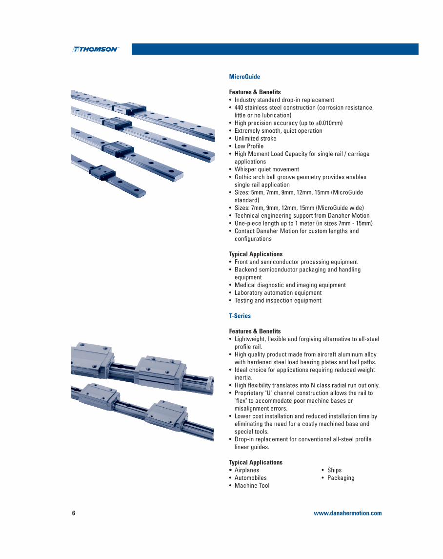
MicroGuide
Features & Benefits
little or no lubrication)
applications
single rail application
standard)
configurations
Typical Applications
T-Series
Features & Benefits
profile rail.
with hardened steel load bearing plates and ball paths.
inertia.
misalignment errors.
eliminating the need for a costly machined base and special tools.
linear guides.
Typical Applications

www.danahermotion.com 7
Profile Rail Linear Guides 500 Series Ball
Profile Rail
500 Series Ball 500 Series Roller AccuMini MicroGuide T-Series
Standard Narrow Standard Narrow Standard Standard Wide Standard
––– Long Long Long Short Long Long
––– ––– ––– ––– High High ––– ––– ––– ––– ––– ––– ––– ––– ––– –––
SIZE
MM
5
7
9
10
12
15
20
25
30
35
45
55
65
Style A B C D E F G A B C D A N/A N/A A G E F
Page 19 19 21 21 23 23 25 53 53 55 55 73 76 78 85 87 87 85
Application Criteria
Feature 500 Series Ball 500 Series Roller AccuMini MicroGuide T-Series
Load Capacity
Equivalent Loads all directions
Ultra Compactness
High Travel Accuracy
Rigidity
Smoothness
Friction Characteristic
Admissable Speed
Ease of Installation
Lightweight
Industry Standard Dimensions
Page 8 42 71 75 82
Assortment

www.danahermotion.com8
Industry standard dimensions
High load capacities in all directions
Multiple rail accuracies Multiple rail mounting hole plug options,or rails that mount up from underneath are available
Both sides of rail are reference edges
Six-runner block attachment boltsper carriage for superior systemrigidity
Universal mounting holes–runner blocks can be attached from top or bottom
Multiple lubrication inlet points, easyfield modification
Superior rail straightness as a resultof advanced grinding and straighteningtechnology
Modular accessories for on site upgrade without having toremove the carriage from the rail
Low friction double lip seal on all standard carriages
High rigidity from optimizedtrapezoidal profile, allows for single carriage application
Speeds up to 5 m/sAccelerations up to 100 m/s2
Two point ball contact resultingin low friction
Retained balls when carriage is off therail and when the end cap is removed
Extended standard dowel holeoptions for rails and carriages
Low drag longitudinal seals standard for added protection along rail surface
Corrosion resistance with Duralloy®
Thin Dense Chrome plating optional
One piece rail length up to 6 meters(size 25 and up)
Optimized ball path geometries andtransitions for quiet, smooth operation
Multiple carriage designs, accuracies and preloads available
Patented insert moldedrecirculation path with greasepockets resulting in quiet,low noise operation
Complete interchangeabilitybetween rails and carriages
500 Series Ball Profile Rail Linear Guide
Profile Rail Linear Guides

www.danahermotion.com 9
Profile Rail Linear Guides 500 Series Ball
Profile Rail
FeaturesThe Thomson 500 Series Ball Linear Guide provides long life, exceptional rigidity, high dynamic and static load capacities,accommodation for high moment loads, high running accuracy, multiple sealing options and multiple lubrication inlet options. This allows for on-site field modifications, and interchangeability with competitor offering.
These properties result in improved machine accuracies and rigidity resulting in reduced vibration extending machine and tool life. This has a direct effect on operational efficiency resulting in cost savings for the user.
Available in 7 carriage designs, and sizes 15 to 45mm.
Materials Linear GuidesThe 500 Series Ball Linear Guides are produced from high
size 15 rail which is through hardened). The end cap is constructed of a high strength, glass filled nylon with nitrile
consistency of materials from the source, allowing us to
InterchangeabilityThe 500 Series Ball Linear Guides are completely interchangeable. Any carriage can be run on any rail of the same accuracy without compromising system accuracy. This is the result of our stringent manufacturing process controls.
Accuracy and PreloadThe 500 Series Ball Linear Guides are available in three different accuracy classes, three different preload ranges and with clearance to allow for customization to your application needs.
StraightnessThe 500 Series Ball rail is subjected to multiple straightening processes during and after grinding of the roller paths.
These added processes and inspections result in some of the straightest rails in the market today, improving machine accuracies wherever the 500 Series Ball is used.
RigidityThe 500 Series Ball Linear Guide rail utilizes a special trapezoidal profile that maximizes the carriage cross section, resulting in the highest possible rigidity.
500 Series Ball Profile Rail Linear Guide

www.danahermotion.com10
500 Series Ball Profile Rail Linear Guide
Running Smoothness / Low NoiseThe running smoothness and low noise are the result of a patented, custom insert molded recirculation path that has an optimized geometric shape and minimal transitions, to
operation.
In addition, the balls make contact at only two points between rail and carriage. As a result, friction is reduced to
Back-to-BackThe 500 Series Linear Guide utilizes a back-to-back bearing arrangement, resulting in added rigidity. As a result, the 500 Series Ball can be used in single rail applications.
Internal Grease PocketsThe patented insert molded recirculation path has built in grease pockets. These provide an extra level of security by
to help extend life.
The pocket and area between the balls provide greater grease
designed linear guide bearing.
Multiple Lubrication OptionsThe standard end cap is designed for flexibility. The end cap comes standard with four lubrication inlet options. These inlet options are easily changed on-site in the field or can be supplied from the factory.
allow the user to make these changes easily in the field to optimize the system performance. In addition, they allow for ease in maintenance – all without removing the carriage from the rail.
Profile Rail Linear Guides
www.danahermotion.com 11
Profile Rail Linear Guides 500 Series Ball
Profile Rail
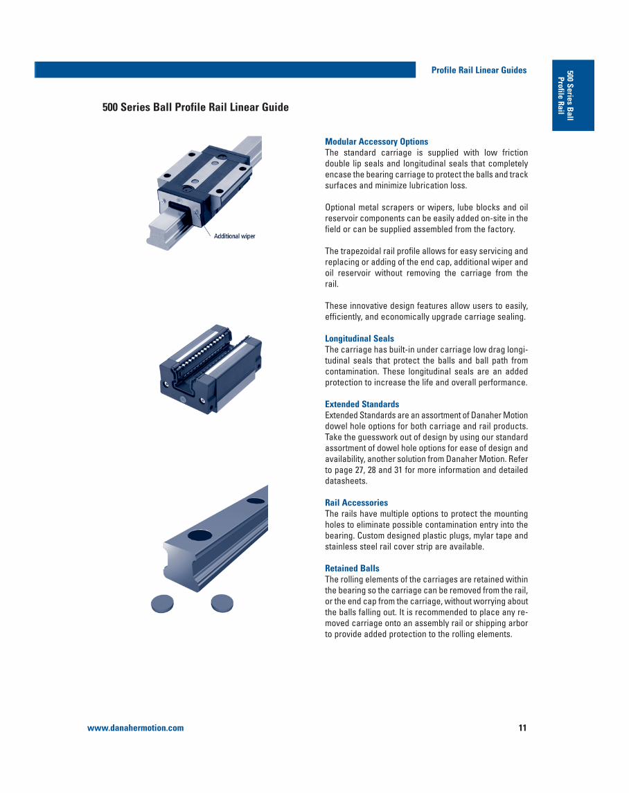
Modular Accessory OptionsThe standard carriage is supplied with low friction double lip seals and longitudinal seals that completely encase the bearing carriage to protect the balls and track surfaces and minimize lubrication loss.
Optional metal scrapers or wipers, lube blocks and oil reservoir components can be easily added on-site in the field or can be supplied assembled from the factory.
The trapezoidal rail profile allows for easy servicing and replacing or adding of the end cap, additional wiper and oil reservoir without removing the carriage from the rail.
These innovative design features allow users to easily, efficiently, and economically upgrade carriage sealing.
Longitudinal SealsThe carriage has built-in under carriage low drag longi-tudinal seals that protect the balls and ball path from contamination. These longitudinal seals are an added protection to increase the life and overall performance.
Extended StandardsExtended Standards are an assortment of Danaher Motion dowel hole options for both carriage and rail products. Take the guesswork out of design by using our standard assortment of dowel hole options for ease of design and availability, another solution from Danaher Motion. Refer to page 27, 28 and 31 for more information and detailed datasheets.
Rail AccessoriesThe rails have multiple options to protect the mounting holes to eliminate possible contamination entry into the bearing. Custom designed plastic plugs, mylar tape and stainless steel rail cover strip are available.
Retained BallsThe rolling elements of the carriages are retained within the bearing so the carriage can be removed from the rail, or the end cap from the carriage, without worrying about the balls falling out. It is recommended to place any re-moved carriage onto an assembly rail or shipping arbor to provide added protection to the rolling elements.
500 Series Ball Profile Rail Linear Guide

www.danahermotion.com12
500 Series Ball Profile Rail Linear Guide
Modular Accessory Exploded View
Profile Rail Linear Guides
and 531RCS)* Can be installed without removing carriage from the
rail
The modular building block design of the 500 Series Ball Profile Rail Linear Guide assembly allows for easy on-site
without the need to remove the carriage from the rail.
Standard end cap*(531 EC)
Integral double lip seal
Recirculation path
Oil reservoir*(531 OW)
Additional wiper*(531 WR or VR)
Metal scraper(531 ZZ)
Grease fitting Attaching bolts
Plastic plugs(531 HP)
Rail(521)
Balls
Standard end cap(531 EC)

www.danahermotion.com 13
Profile Rail Linear Guides 500 Series Ball
Profile Rail500 Series Ball Standard Carriages
15
20
25
30
35
45
20
25
30
35
45
15
20
25
30
35
20
25
30
35
1500
3000
6000
6000
6000
6000
3000
6000
6000
6000
6000
1500
3000
6000
6000
6000
3000
6000
6000
6000
511H15A0--
511H20A0--
511H25A0--
511H30A0--
511H35A0--
511H45A0--
511H20B0--
511H25B0--
511H30B0--
511H35B0--
511H45B0--
511H15C0--
511H20C0--
511H25C0--
511H30C0--
511H35C0--
511H20D0--
511H25D0--
511H30D0--
511H35D0--
HPUHPUHPUHPUHPUHPUHPUHPUHPUHPUHPUHPUHPUHPUHPUHPUHPUHPUHPUHPU
511H15A1511P15A1511U15A1511H20A1511P20A1511U20A1511H25A1511P25A1511U25A1511H30A1511P30A1511U30A1511H35A1511P35A1511U35A1511H45A1511P45A1511U45A1511H20B1511P20B1511U20B1511H25B1511P25B1511U25B1511H30B1511P30B1511U30B1511H35B1511P35B1511U35B1511H45B1511P45B1511U45B1511H15C1511P15C1511U15C1511H20C1511P20C1511U20C1511H25C1511P25C1511U25C1511H30C1511P30C1511U30C1511H35C1511P35C1511U35C1511H20D1511P20D1511U20D1511H25D1511P25D1511U25D1511H30D1511P30D1511U30D1511H35D1511P35D1511U35D1
511H15A2511P15A2511U15A2511H20A2511P20A2511U20A2511H25A2511P25A2511U25A2511H30A2511P30A2511U30A2511H35A2511P35A2511U35A2511H45A2511P45A2511U45A2511H20B2511P20B2511U20B2511H25B2511P25B2511U25B2511H30B2511P30B2511U30B2511H35B2511P35B2511U35B2511H45B2511P45B2511U45B2511H15C2511P15C2511U15C2511H20C2511P20C2511U20C2511H25C2511P25C2511U25C2511H30C2511P30C2511U30C2511H35C2511P35C2511U35C2511H20C2511P20D2511U20D2511H25D2511P25D2511U25D2511H30D2511P30D2511U30D2511H35D2511P35D2511U35D2
-511P15A3511U15A3
-511P20A3511U20A3
-511P25A3511U25A3
-511P30A3511U30A3
-511P35A3511U35A3
-511P45A3511U45A3
-511P20B3511U20B3
-511P25B3511U25B3
-511P30B3511U30B3
-511P35B3511U35B3
-511P45B3511U45B3
-511P15C3511U15C3
-511P20C3511U20C3
-511P25C3511U25C3
-511P30C3511U30C3
-511P35C3511U35C3
-511P20D3511U20D3
-511P25D3511U25D3
-511P30D3511U30D3
-511P35D3511U35D3
521H15A521P15A521U15A521H20A521P20A521U20A521H25A521P25A521U25A521H30A521P30A521U30A521H35A521P35A521U35A521H45A521P45A521U45A521H20A521P20A521U20A521H25A521P25A521U25A521H30A521P30A521U30A521H35A521P35A521U35A521H45A521P45A521U45A521H15A521P15A521U15A521H20A521P20A521U20A521H25A521P25A521U25A521H30A521P30A521U30A521H35A521P35A521U35A521H20A521P20A521U20A521H25A521P25A521U25A521H30A521P30A521U30A521H35A521P35A521U35A
SizeStyle
StandardCarriage A
B
C
NarrowLong
Carriage
NarrowCarriage
StandardLong
Carriage
D
AccuracyClearance 0.03C 0.08C
PreloadBasic Part Number
0.13C
Appropriate RailStandard Style
Max. Single PieceRail Length (mm)
Danaher Motion offers six carriage styles with six mounting holes allowing for additional mounting configurations in the field or for retrofitting. All provide superior rigidity and design flexibility.

www.danahermotion.com14
Profile Rail Linear Guides
15
25
30
35
45
25
30
35
45
15
20
1500
6000
6000
6000
6000
6000
6000
6000
6000
1500
3000
511H15E0- -
511H25E0- -
511H30E0- -
511H35E0- -
511H45E0- -
511H25F0- -
511H30F0- -
511H35F0- -
511H45F0- -
511H15G0- -
511H20G0- -
HPUHPUHPUHPUHPUHPUHPUHPUHPUHPUHPU
511H15E1511P15E1511U15E1511H25E1511P25E1511U25E1511H30E1511P30E1511U30E1511H35E1511P35E1511U35E1511H45E1511P45E1511U45E1511H25F1511P25F1511U25F1511H23F1511P30F1511U30F1511H35F1511P35F1511U35F1511H45F1511P45F1511U45F1511H15G1511P15G1511U15G1511H20G1511P20G1511U20G1
511H15E2511P15E2511U15E2511H25E2511P25E2511U25E2511H30E2511P30E2511U30E2511H35E2511P35E2511U35E2511H45E2511P45E2511U45E2511H25F2511P25F2511U25F2511H30F2511P30F2511U30F2511H35F2511P35F2511U35F2511H45F2511P45F2511U45F2511H15G2511P15G2511U15G2511H20G2511P20G2511U20G2
- 511P15E3511U15E3
- 511P25E3511U25E3
- 511P30E3511U30E3
- 511P35E3511U35E3
- 511P45E3511U45E3
- 511P20F3511U20F3
- 511P30F3511U30F3
- 511P35F3511U35F3
- 511P45F3511U45F3
- 511P15G3511U15G3
- 511P20G3511U20G3
521H15A521P15A521U15A521H25A521P25A521U25A521H30A521P30A521U30A521H35A521P35A521U35A521H45A521P45A521U45A521H25A521P25A521U25A521H30A521P30A521U30A521H35A521P35A521U35A521H45A521P45A521U45A521H15A521P15A521U15A521H20A521P20A521U20A
SizeStyle
NarrowHigh
Carriage E
F
GNarrowShort
Carriage
NarrowHighLong
Carriage
AccuracyClearance 0.03C 0.08C
PreloadBasic Part Number
0.13C
Appropriate RailStandard Style
Max. Single PieceRail Length (mm)
Extended Standard Carriage OptionsThe carriages are also available with the Thomson standard dowel holes or lubrication inlets as shown on pages 27 to 31 or special lubricants either from stock or with a short lead-time.
Rail Types and AccessoriesThe rails are available in two configurations:
The standard 521 rail mounting holes can be plugged or sealed after installation with the options below.
Plastic Plugs531HP plastic plugs are an inexpensive and simple method to seal the rail attachment bolt area. The plastic plugs are easily driven in place to any rail with a soft non-metallic drift. They can easily be removed.
Mylar Tape
the top surface of the rail. Part number 531RT is available in 3 meter lengths.
Stainless Steel Cover Strip
easily installed with the proper mounting tool.
Type A Type U

www.danahermotion.com 15
Profile Rail Linear Guides 500 Series Ball
Profile Rail
The carriage is designed with modular sealing and lubrication options for simple on-site field modification or can be supplied factory direct.
The standard carriage end cap has an integral low friction double lip seal and longitudinal seal that completely encase the bearing carriage. The double lip design keeps contaminants out and lubrication in. It also allows for grease to purge out of the carriage to prevent excessive lubrication, which can result in higher operating temperatures. This double lip design can be used with oil lubrication.
cation inlet centered with a specially designed lubricant channel to direct the lubrication to individual ball tracks. The lubrication inlet can be easily changed in the field or supplied from the factory with a side inlet or top inlet.
Additional SealThe 531 WR and 531 VR seals provide an additional level of protection from contaminants to the assembly. These additional components can easily be added on-site without removing the carriage from the rail. They are
simple.
531 VR is constructed from durable Viton®
These seals can be used in conjunction with other optional modular accessories providing an easy upgrade to the standard seal. These can be easily installed on-site in the field or can be supplied from the factory.
Metal ScraperThe Type 531 ZZ Metal Scraper made of stainless steel, serves as an added protection to the seal lips against large dirt particles, metal shavings or chips. Large contaminants are easily pushed away providing an extra level of protection to the seal lips. The Metal Scraper is easily installed in conjunction with the other optional modular accessories providing you with an easy upgrade to the standard seal. These can be easily installed on-site in the field or can be supplied from the factory.
Additional Seal Types and Lubrication Accessories

www.danahermotion.com16
Oil ReservoirThe Type 531 OW oil reservoir is a cost effective, automatic lubrication system. It is constructed with an integrated oil reservoir that provides a uniform, consistent lubricating oil to the ball paths for extended periods of time. The Type
for a routine maintenance schedule, assures lubrication
reservoir can be easily installed in conjunction with other optional modular accessories providing an easy upgrade to the standard seals. These can be easily installed on-site in the field or can be supplied from the factory.
Lube BlockThe 531 LL Lube Block is a solid lubricant that is a mixture of polymers, oils and selected additives that reduce the
venting premature failures. The oil diffuses, lubricating the ball path surfaces by capillary action. Additional oil is suppliedto the ball path surfaces from the polymer. For additional protection the assembly is packed with EP2 grease. There is no need for maintenance or additional lubrication duringthe life of the Lube Block filled bearing. The 531 LL Lube Block can be easily installed in conjunction with the other optional modular accessories providing an easy upgrade to the standard seal. These can be easily installed on-site in the field or can be supplied from the factory.
BellowsStandard bellows are available for all assemblies. The bellows cover the entire length of the rail. The bellows are used to provide additional protection against dirt, dust
little time. Retrofitting is possible when the rail ends are drilled for the attachment of the end plate 531. Bellows are available in three styles:
not exceed the carriage
environments with a 90kg load bearing capacity
The bellow can be easily installed in conjunction with other optional modular seals providing you with a simple upgrade to the standard seal. These can be installed on-site in the field or can be supplied from the factory.
Note: Additional modular accessories add additional drag to the carriage assembly resulting in increased start up friction and power consumption.
Profile Rail Linear Guides
For ordering information or for additional Seal Types and
Lubrication Accessories, see pages 35 to 36.
Type Relative Drag
Standard carriage
Viton®
Relative Drag Comparison for Design Consideration

www.danahermotion.com 17
Profile Rail Linear Guides 500 Series Ball
Profile Rail
Part Numbering Description
500 Series Ball
StandardSTANDARD OPTIONS
Ball Carriage
500 Series Profile Carriage
Product Type 1 Carriage
5 1 1 H 25 A 1 ES1 SML W Z D
SpecialsSM Special per customer print
Extended Standards - OptionsES1 6mm Dowel Hole - Slip FitES2 10mm Dowel Hole - Slip FitES3 1/4” Dowel Hole - Slip FitES4 3/8” Dowel Hole - Slip FitES10 Side lubrication in end capsES11 Top lubrication in end capsES12 (2) 6mm Dowel Holes - Press FitES13 (2) 10mm Dowel Holes - Press FitES14 (2) 1/4” Dowel Holes - Press FitES15 (2) 3/8” Dowel Holes - Press FitG1 Greased with Mobilux® EP2 G2 Greased with Krytox® GPL227GS Greased per customer
specification
Accuracy Class2
H High Grade P Precision Grade U Ultra Precision Grade
Size15, 20, 25, 30, 35, 45
Carriage Style A Standard B Standard Long C Narrow D Narrow Long E Narrow High F Narrow Long High G Narrow Short
Preload0 Clearance1 Approximately 0, 03 C2 Approximately 0, 08 C3 Approximately 0, 13 C
(Available in P and U grades only.)
Type 1 Ball
Accessories1
L Long Life Lube Block N Additional Oil Reservoir W Additional Rubber Wiper V Additional Viton Wiper Z Metal ScraperC Bellow Clips
Coating Option D Duralloy® Thin Dense Chrome
1. Accessory combination part numbers are listed from carriage end cap outward. Not all combinations are available. For specific combination availability see pages 33-34 or consult Danaher Motion.
2. The 500 Series Ball lowest accuracy grade is High as a result of
offer Normal grade accuracy, our High grade is our Normal grade.

www.danahermotion.com18
Profile Rail Linear Guides
OPTIONSStandardSTANDARD STANDARD
Ball Rail
500 Series Profile Rail
Product Type 2 Rail
5 2 1 H 25 A D SM +xxxx Y= (see note 1) DH1
Length (mm) xxxx Customer Specified Length RL1500 Stock Length2 Size 15 RL3000 Stock Length2 Size 20 and Up RL6000 Stock Length2 Size 25 and Up
SpecialsSM Special Per Customer Print
Machined Options DH1 6mm Dowel Hole + Slot DH2 10mm Dowel Hole + Slot DH3 1⁄4” Dowel Hole + Slot DH4 3⁄8” Dowel Hole + Slot JT4 Butt Joint E Bellow Clips Attached
Accuracy Class H High Grade P Precision Grade U Ultra Precision Grade
Size15, 20, 25,30, 35, 45
Rail Style A Standard U Bolt up from Bottom C Cover Strip3
Coating Option D Duralloy® (H and P accuracy only)
Type 1 Ball
Ball Accessories
500 Series Profile Rail
Product Type3 Accessory
5 3 1 EC 25
Size15, 20, 25,30, 35, 45
Rail Hole Covers or Plugs HP Plastic Rail Plugs RT Mylar Rail TapeRCS Rail Cover Strip1, 2
RCT Rail Cover Installation ToolRCP Rail Cover End Cap
Modular Seal Accessories3
EC Replacement End Cap ECH Replacement End Cap for
E and F Style Carriage WR Rubber WiperVR Viton® WiperZZ Metal Scraper OW Oil Reservoir LL Lube Block LS Replacement Spring for LL Option
Type1 Ball
Mounting Assembly ToolsMT Mounting Rail
BellowsBB Low Profile Bellows1
BC High Compression Bellows1
BW Walk On Bellows1
CC Bellow clips for Carriage CR Bellow clips for Rail
1. Y = Distance from end of rail to center of first mounting hole, Y1 = Y2 unless specified
2. Stock length rails are considered random length, total length may
customer who will cut to length.
3. Cover strip available size 25 and up only.
See page 128 for more information and templates.
1. Bellows and rail cover strip must include length at time of order. Example: 531BB25 + 1000mm. See page 126 on how to calculate bellows length.
2. Cover strip available size 25 and up only.3. Two standard screws included with each item. Screws for attaching
this accessory to carriage and not combinations of accessories.
www.danahermotion.com 19
Profile Rail Linear Guides 500 Series Ball
Profile Rail
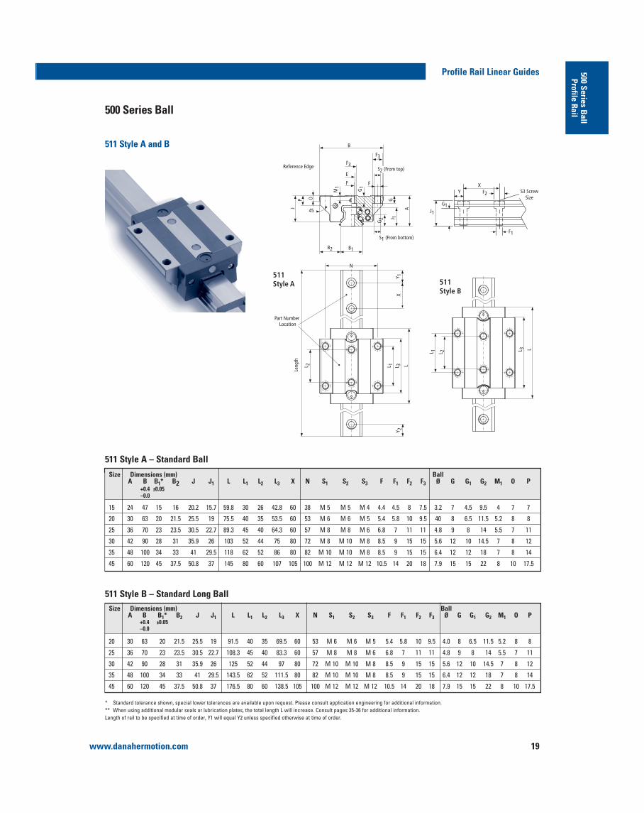
511 Style A and B
500 Series Ball
511 Style A – Standard Ball
511 Style B – Standard Long Ball
45
B2
M1
G1
G2 J 1
A
GOPJ
B
F3
F3
F F
E
B1
Leng
th
L 2 L 1 L 3 L
Y 2X
Y 1511Style A
L 1 L 2 L 3 L
511Style B
Reference Edge
Part Number Location
N
S2 (From top)
S1 (From bottom)
J1
YX
S3 ScrewSize
F1
F2
G1
Size Dimensions (mm) BallA B B1* B2 J J1 L L1 L2 L3 X N S1 S2 S3 F F1 F2 F3 Ø G G1 G2 M1 O P
+0.4 ±0.05 –0.0
20 30 63 20 21.5 25.5 19 91.5 40 35 69.5 60 53 M 6 M 6 M 5 5.4 5.8 10 9.5 4.0 8 6.5 11.5 5.2 8 8
25 36 70 23 23.5 30.5 22.7 108.3 45 40 83.3 60 57 M 8 M 8 M 6 6.8 7 11 11 4.8 9 8 14 5.5 7 11
30 42 90 28 31 35.9 26 125 52 44 97 80 72 M 10 M 10 M 8 8.5 9 15 15 5.6 12 10 14.5 7 8 12
35 48 100 34 33 41 29.5 143.5 62 52 111.5 80 82 M 10 M 10 M 8 8.5 9 15 15 6.4 12 12 18 7 8 14
45 60 120 45 37.5 50.8 37 176.5 80 60 138.5 105 100 M 12 M 12 M 12 10.5 14 20 18 7.9 15 15 22 8 10 17.5
Size Dimensions (mm) BallA B B1* B2 J J1 L L1 L2 L3 X N S1 S2 S3 F F1 F2 F3 Ø G G1 G2 M1 O P
+0.4 ±0.05 –0.0
15 24 47 15 16 20.2 15.7 59.8 30 26 42.8 60 38 M 5 M 5 M 4 4.4 4.5 8 7.5 3.2 7 4.5 9.5 4 7 7
20 30 63 20 21.5 25.5 19 75.5 40 35 53.5 60 53 M 6 M 6 M 5 5.4 5.8 10 9.5 40 8 6.5 11.5 5.2 8 8
25 36 70 23 23.5 30.5 22.7 89.3 45 40 64.3 60 57 M 8 M 8 M 6 6.8 7 11 11 4.8 9 8 14 5.5 7 11
30 42 90 28 31 35.9 26 103 52 44 75 80 72 M 8 M 10 M 8 8.5 9 15 15 5.6 12 10 14.5 7 8 12
35 48 100 34 33 41 29.5 118 62 52 86 80 82 M 10 M 10 M 8 8.5 9 15 15 6.4 12 12 18 7 8 14
45 60 120 45 37.5 50.8 37 145 80 60 107 105 100 M 12 M 12 M 12 10.5 14 20 18 7.9 15 15 22 8 10 17.5

www.danahermotion.com20
500 Series Ball
511 Style A and B
Profile Rail Linear Guides
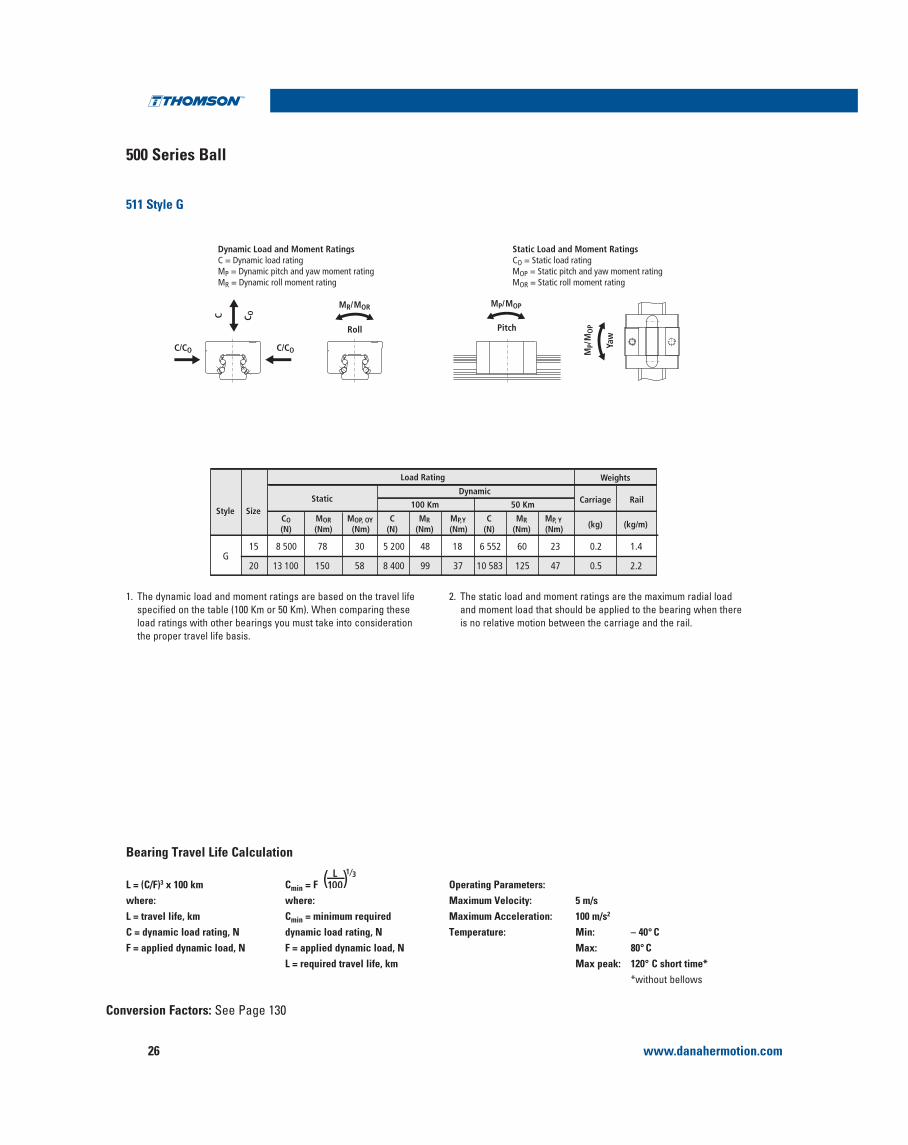
Dynamic Load and Moment Ratings C = Dynamic load rating MP = Dynamic pitch and yaw moment rating MR = Dynamic roll moment rating
Static Load and Moment Ratings CO = Static load rating MOP = Static pitch and yaw moment rating MOR = Static roll moment rating
C/COC/CO
MR /MOR
PitchRoll
Yaw
MP/MOP
MP/
MO
P
C C O
L = (C/F)3 x 100kmwhere:L = travel life, kmC = dynamic load rating, NF = applied dynamic load, N
Cmin = F ( )L100
1⁄3
where:Cmin = minimum required dynamic load rating, NF = applied dynamic load, NL = required travel life, km
Operating Parameters:Maximum Velocity: 5 m/sMaximum Acceleration: 100 m/s2
Temperature: Min: – 40° CMax: 80° CMax peak: 120° C short time*
*without bellows
Bearing Travel Life Comparison
Conversion Factors: See Page 130
19 600 181 146 9 000 83 6715
Style SizeMOP, OY
(Nm)MOR(Nm)
CO(N)
C(N)
MR(Nm)
MP,Y(Nm)
Static
11 339 105 84 0.2 1.4
(kg) (kg/m)C
(N)MR
(Nm)MP, Y(Nm)
Dynamic
100 Km 50 Km Carriage Rail
Load Rating Weights
31 400 373 292 14 400 171 13420 18 143 215 169 0.5 2.2
46 100 631 513 21 100 289 23525 26 584 364 296 0.7 3.0
63 700 1 084 829 29 200 497 38030 36 790 626 479 1.2 4.3
84 400 1 566 1 252 38 700 718 57435 48 759 905 723 1.8 5.4
134 800 3 193 2 498 61 900 1 466 1 147 45 77 989 1 847 1 445 3.3 8.8
41 100 490 495 17 400 206 20820 21 923 260 262 0.6 2.2
60 300 825 863 25 500 349 36525
A
B32 128 440 460 0.9 3.0
83 300 1 414 1 390 35 300 599 58930 44 475 755 742 1.5 4.3
110 300 2 048 2 104 46 700 867 89135 58 838 1 092 1 123 2.3 5.4
176 300 4 175 4 199 74 700 1 769 1 779 45 94 116 2 229 2 241 4.2 8.8
1. The dynamic load and moment ratings are based on the travel life
load ratings with other bearings you must take into consideration the proper travel life basis.
2. The static load and moment ratings are the maximum radial load and moment load that should be applied to the bearing when there is no relative motion between the carriage and the rail.
www.danahermotion.com 21
Profile Rail Linear Guides 500 Series Ball
Profile Rail500 Series Ball Profile Rail Linear Guide
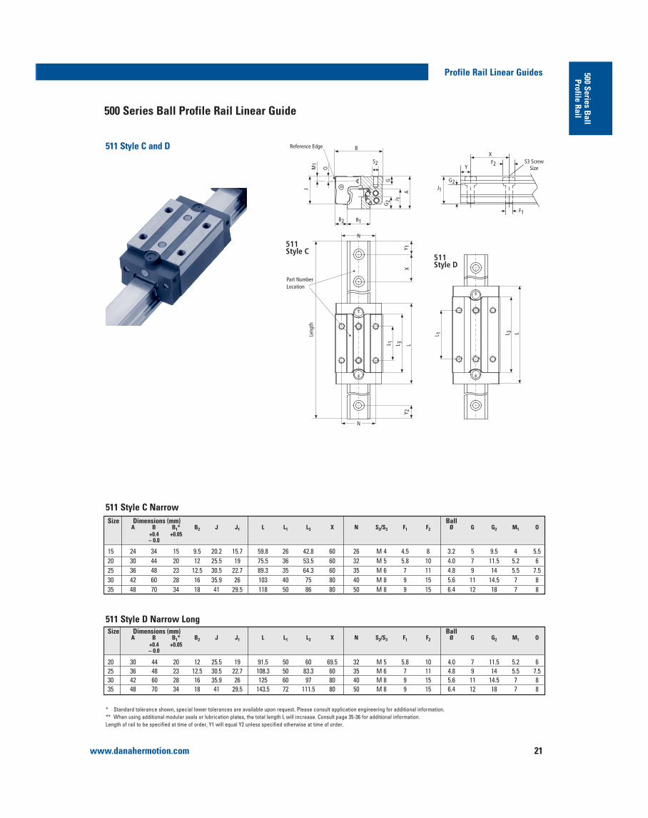
511 Style C and D
511Style C
511Style D
JM
1
O
B
G2 J 1
G
A
B1B2
Y 1X
L 1 L 3 LY 2
L 1 L 3 LLeng
th
Reference Edge
Part Number Location
N
N
S2
J1
F1
Y
XS3 Screw
SizeF2
G2
511 Style C Narrow
511 Style D Narrow Long
Size Dimensions (mm) BallA B B1* B2 J J1 L L1 L3 X N S2/S3 F1 F2 Ø G G2 M1 O
+0.4 +0.05 – 0.0
15 24 34 15 9.5 20.2 15.7 59.8 26 42.8 60 26 M 4 4.5 8 3.2 5 9.5 4 5.520 30 44 20 12 25.5 19 75.5 36 53.5 60 32 M 5 5.8 10 4.0 7 11.5 5.2 625 36 48 23 12.5 30.5 22.7 89.3 35 64.3 60 35 M 6 7 11 4.8 9 14 5.5 7.530 42 60 28 16 35.9 26 103 40 75 80 40 M 8 9 15 5.6 11 14.5 7 8 35 48 70 34 18 41 29.5 118 50 86 80 50 M 8 9 15 6.4 12 18 7 8
Size Dimensions (mm) BallA B B1* B2 J J1 L L1 L3 X N S2/S3 F1 F2 Ø G G2 M1 O
+0.4 +0.05 – 0.0
20 30 44 20 12 25.5 19 91.5 50 60 69.5 32 M 5 5.8 10 4.0 7 11.5 5.2 625 36 48 23 12.5 30.5 22.7 108.3 50 83.3 60 35 M 6 7 11 4.8 9 14 5.5 7.530 42 60 28 16 35.9 26 125 60 97 80 40 M 8 9 15 5.6 11 14.5 7 835 48 70 34 18 41 29.5 143.5 72 111.5 80 50 M 8 9 15 6.4 12 18 7 8

www.danahermotion.com22
500 Series Ball
511 Style C and D
Profile Rail Linear Guides
L = (C/F)3 x 100 kmwhere:L = travel life, kmC = dynamic load rating, NF = applied dynamic load, N
Cmin = F ( )L100
1⁄3
where:Cmin = minimum required dynamic load rating, NF = applied dynamic load, NL = required travel life, km
Operating Parameters:Maximum Velocity: 5 m/sMaximum Acceleration: 100 m/s2
Temperature: Min: – 40° CMax: 80° CMax peak: 120° C short time*
*without bellows
Bearing Travel Life Comparison
Conversion Factors: See Page 130
C/CO C/CO
MR/MOR
Roll Pitch
MP/MOP
MP/
MO
P
Yaw
C C ODynamic Load and Moment Ratings C = Dynamic load rating MP = Dynamic pitch and yaw moment rating MR = Dynamic roll moment rating
Static Load and Moment Ratings CO = Static load rating MOP = Static pitch and yaw moment rating MOR = Static roll moment rating
1. The dynamic load and moment ratings are based on the travel life
load ratings with other bearings you must take into consideration the proper travel life basis.
2. The static load and moment ratings are the maximum radial load and moment load that should be applied to the bearing when there is no relative motion between the carriage and the rail.
19 600 181 146 9 000 83 6715
Style SizeMOP, OY
(Nm)MOR(Nm)
CO(N)
C(N)
MR(Nm)
MP,Y(Nm)
Static
11 339 105 84 0.2 1.4
(kg) (kg/m)C
(N)MR
(Nm)MP, Y(Nm)
Dynamic
100 Km 50 Km Carriage Rail
Load Rating Weights
31 400 373 292 14 400 171 13420 18 143 215 169 0.5 2.2
46 100 631 513 21 100 289 23525 26 584 364 296 0.7 3.0
63 700 1 084 829 29 200 497 38030 36 790 626 479 1.2 4.3
84 400 1 566 1 252 38 700 718 57435 48 759 905 723 1.8 5.4
41 100 490 495 17 400 206 20820 21 923 260 262 0.6 2.2
60 300 825 863 25 500 349 36525
C
D32 128 440 460 0.9 3.0
83 300 1 414 1 390 35 300 599 58930 44 475 755 742 1.5 4.3
110 300 2 048 2 104 46 700 867 89135 58 838 1 092 1 123 2.3 5.4

www.danahermotion.com 23
Profile Rail Linear Guides 500 Series Ball
Profile Rail500 Series Ball Profile Rail Linear Guide
511 Style E and F
M1
J
O G
A
J 1
G2
B2 B1
B
Leng
th
Y 2
L 1 L 3 L
L 1 L 3 L
XY 1
511Style E
511Style F
Part Number Location
Reference Edge
J1
G2
YX
S3 Screw Size
F1
F2
N
N
S2
511 Style E Narrow High
511 Style F Narrow Long HighSize Dimensions (mm) Ball
A B B1* B2 J J1 L L1 L3 X N s2/s3 F1 F2 Ø` G G2 M1 O +0.4 +0.05 -0.0
25 40 48 23 12.5 34.5 22.7 108.3 50 83.3 60 35 M 6 7 11 4.8 9 14 9.5 1130 45 60 28 16 38.9 26 125 60 97 80 40 M 8 9 15 5.6 11 14.5 10 1135 55 70 34 18 48 29.5 143.5 72 111.5 80 50 M 8 9 15 6.4 12 18 14 1545 70 86 45 20.5 60.8 37 176.5 80 138.5 105 60 M 10 14 20 7.9 18 22 18 19
Size Dimensions (mm) BallA B B1* B2 J J1 L L1 L3 X N s2/s3 F1 F2 Ø` G G2 M1 O
+0.4 +0.05 -0.0
15 28 34 15 9.5 24.2 15.7 59.8 26 42.8 60 26 M 4 4.5 8 3.2 6 9.5 8 625 40 48 23 12.5 34.5 22.7 89.3 35 64.3 60 35 M 6 7 11 4.8 9 14 9.5 1130 45 60 28 16 38.9 26 103 40 75 80 40 M 8 9 15 5.6 11 14.5 10 1135 55 70 34 18 48 29.5 118 50 86 80 50 M 8 9 15 6.4 12 18 14 1545 70 86 45 20.5 60.8 37 145 60 107 105 60 M 10 14 20 7.9 18 22 18 19

www.danahermotion.com24
500 Series Ball
511 Style E and F
Profile Rail Linear Guides
Conversion Factors: See Page 130
Dynamic Load and Moment Ratings C = Dynamic load rating MP = Dynamic pitch and yaw moment rating MR = Dynamic roll moment rating
Static Load and Moment Ratings CO = Static load rating MOP = Static pitch and yaw moment rating MOR = Static roll moment rating
C/CO C/CO
MR/MOR
Roll Pitch
MP/MOP
Mp/
MO
P
Yaw
C C O
L = (C/F)3 x 100 kmwhere:L = travel life, kmC = dynamic load rating, NF = applied dynamic load, N
Cmin = Fwhere:Cmin = minimum required dynamic load rating, NF = applied dynamic load, NL = required travel life, km
Operating Parameters:Maximum Velocity: 5 m/sMaximum Acceleration: 100 m/s2
Temperature: Min: – 40° CMax: 80° CMax peak: 120° C short time*
*without bellows
Bearing Travel Life Calculation
( )L100
1⁄3
1. The dynamic load and moment ratings are based on the travel life
load ratings with other bearings you must take into consideration the proper travel life basis.
2. The static load and moment ratings are the maximum radial load and moment load that should be applied to the bearing when there is no relative motion between the carriage and the rail.
19 600 181 146 9 000 83 6715
Style SizeMOP, OY
(Nm)MOR(Nm)
CO(N)
C(N)
MR(Nm)
MP,Y(Nm)
Static
11 339 105 84 0.2 1.4
(kg) (kg/m)C
(N)MR
(Nm)MP, Y(Nm)
Dynamic
100 Km 50 Km Carriage Rail
Load Rating Weights
0.5 2.246 100 631 513 21 100 289 23525 26 584 364 296
0.7 3.063 700 1 084 829 29 200 497 38030 36 790 626 479
1.2 4.384 400 1 566 1 252 38 700 718 57435 48 759 905 723
134 800 3 193 2 498 61 900 1 466 1 147 45 77 989 1 847 1 445 1.8 5.4
0.6 2.260 300 825 863 25 500 349 36525
E
F
32 128 440 460
0.9 3.083 300 1 414 1 390 35 300 599 58930 44 475 755 742
1.5 4.3110 300 2 048 2 104 46 700 867 89135 58 838 1 092 1 123
176 300 4 175 4 199 74 700 1 769 1 779 45 94 116 2 229 2 241 2.3 5.4

www.danahermotion.com 25
Profile Rail Linear Guides 500 Series Ball
Profile Rail500 Series Ball Profile Rail Linear Guide
511 Style G
511 Style G Narrow Short
JM
1
O
B
G2 J 1
G
A
B1B2
Y 1X
L 3 LY 2
L 1 L 3 L
Leng
th
Reference Edge
Part Number Location
N
S2
J1
F1
Y
XS3 Screw
SizeF2
G2
Size Dimensions (mm) BallA B B1* B2 J J1 L L3 X N s2/s3 F1 F2 Ø G G2 M1 O
+0.4 +0.05 -0.0
15 24 34 15 9.5 20.2 15.7 37.6 20.6 60 26 M4 4.5 8 3.2 6 9.5 4 620 28 44 20 12 23.5 19 47.7 25.7 60 32 M5 5.8 10 4.0 6 11.5 4.2 4
www.danahermotion.com26
500 Series Ball
511 Style G
Profile Rail Linear Guides
Conversion Factors: See Page 130
L = (C/F)3 x 100 kmwhere:L = travel life, kmC = dynamic load rating, NF = applied dynamic load, N
Cmin = Fwhere:Cmin = minimum required dynamic load rating, NF = applied dynamic load, NL = required travel life, km
Operating Parameters:Maximum Velocity: 5 m/sMaximum Acceleration: 100 m/s2
Temperature: Min: – 40° CMax: 80° CMax peak: 120° C short time*
*without bellows
Bearing Travel Life Calculation
( )L100
1⁄3
1. The dynamic load and moment ratings are based on the travel life
load ratings with other bearings you must take into consideration the proper travel life basis.
2. The static load and moment ratings are the maximum radial load and moment load that should be applied to the bearing when there is no relative motion between the carriage and the rail.
8 500 78 30 5 200 48 1815
Style SizeMOP, OY
(Nm)MOR(Nm)
CO(N)
C(N)
MR(Nm)
MP,Y(Nm)
Static
6 552 60 23 0.2 1.4
(kg) (kg/m)C
(N)MR
(Nm)MP, Y(Nm)
Dynamic
100 Km 50 Km Carriage Rail
Load Rating Weights
13 100 150 58 8 400 99 3720 10 583 125 47 0.5 2.2G
C/CO C/CO
MR/MOR
Roll Pitch
MP/MOP
MP/
MO
P
Yaw
C C ODynamic Load and Moment Ratings C = Dynamic load rating MP = Dynamic pitch and yaw moment rating MR = Dynamic roll moment rating
Static Load and Moment Ratings CO = Static load rating MOP = Static pitch and yaw moment rating MOR = Static roll moment rating

www.danahermotion.com 27
Profile Rail Linear Guides 500 Series Ball
Profile Rail
Carriage Dowel HolesDowel holes are commonly used to ensure proper alignment during installation and replacement of carriages and rails. The standard slip fit dowel hole options for the 500 series Standard Ball Carriages are:
Reference Edge Reference Edge
L12
D D
L12
P
H
P
H
Style A and B Style C, D, E and F
Single DowelSlip Fit
All dimensions in mm, unless otherwise specified.Hole Tolerance D +0/-0.013
ES1 ES2 ES3 ES4 L12 ØD H P ØD H P ØD H P ØD H P
15 15 6 4.5 7 – – – 1/4“ 4.5 7 – – –20 20 6 5 9 – – – 1/4“ 5 9 – – –
Type A 25 22.5 6 6.5 9 – – – 1/4“ 6.5 9 – – –30 26 6 9 12 10 9 12 1/4“ 9 12 3/8“ 9 1235 31 – – – 10 9 14 – – – 3/8“ 9 1445 40 – – – 10 10 18 – – – 3/8“ 10 18
20 20 6 5 9 – – – 1/4“ 5 9 – – –25 22.5 6 6.5 9 – – – 1/4“ 6.5 9 – – –
Type B 30 26 6 9 12 10 9 12 1/4“ 9 12 3/8“ 9 1235 31 – – – 10 9 14 – – – 3/8“ 9 1445 40 – – – 10 10 18 – – – 3/8“ 10 18
15 13 6 4 6 – – – 1/4“ 4 6 – – –20 18 6 6 9 – – – 1/4“ 6 9 – – –
Type C 25 17.5 6 6.5 9 – – – 1/4“ 6.5 9 – – –30 20 6 10 12 10 10 12 1/4“ 10 12 3/8“ 10 1235 25 – – – 10 10 12 – – – 3/8“ 10 12
20 25 6 6 9 – – – 1/4“ 6 9 – – –25 25 6 6.5 9 – – – 1/4“ 6.5 9 – – –
Type D 30 30 6 10 12 10 10 12 1/4“ 10 12 3/8“ 10 1235 36 – – – 10 10 12 – – – 3/8“ 10 12
15 13 6 4 6 – – – 1/4“ 4 6 – – –Type E 25 17.5 6 6.5 9 – – – 1/4“ 6.5 9 – – –
30 20 6 10 12 10 10 12 1/4“ 10 12 3/8“ 10 1235 25 – – – 10 10 12 – – – 3/8“ 10 1245 30 – – – 10 13 12 – – – 3/8“ 13 12
25 25 6 6.5 9 – – – 1/4“ 6.5 9 – – –Type F 30 30 6 10 12 10 10 12 1/4“ 10 12 3/8“ 10 12
35 36 – – – 10 10 12 – – – 3/8“ 10 1245 40 – – – 10 13 12 – – – 3/8“ 13 12
511Style Size

www.danahermotion.com28
Carriage Dowel Holes (continued)
Profile Rail Linear Guides
Reference Edge Reference Edge
L12
DD
L12
P
H
P
H
Style A and B Style C, D, E and F
Double DowelPress Fit
ES12 ES13 ES14 ES15 L12 ØD H P ØD H P ØD H P ØD H P
Type A
Type C
Type E
511Style Size
All dimensions in mm, unless otherwise specified.Hole Tolerance D +0/-0.013
www.danahermotion.com 29
Profile Rail Linear Guides 500 Series Ball
Profile Rail
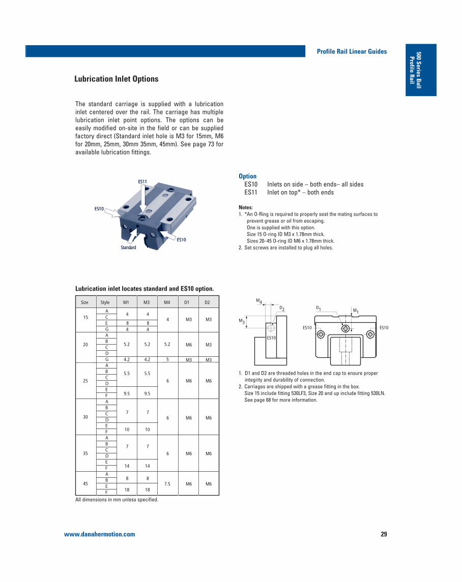
The standard carriage is supplied with a lubrication inlet centered over the rail. The carriage has multiple lubrication inlet point options. The options can be easily modified on-site in the field or can be supplied
for 20mm, 25mm, 30mm 35mm, 45mm). See page 73 for available lubrication fittings.
OptionES10 Inlets on side – both ends– all sidesES11 Inlet on top* – both ends
Notes:
prevent grease or oil from escaping. One is supplied with this option. Size 15 O-ring ID M3 x 1.78mm thick. Sizes 20–45 O-ring ID M6 x 1.78mm thick.
2. Set screws are installed to plug all holes.
Size
158 8
M3 M3
M6 M3
M6 M6
4 4
4 4
4
5.2 5.2 5.2
M3 M34.2 4.2 5
5.5 5.5
6
M6 M66
M6 M66
M6 M67.5
9.5 9.5
7 7
10 10
7 7
14 14
18 18
8 8
20
25
30
35
45
Style M1 M3 M4 D1 D2
ACEGABCDGABCDEFABCDEFABCDEFABEF
D1
ES10
D2
M4
M1
ES10ES10
M3
All dimensions in mm unless specified.
1. D1 and D2 are threaded holes in the end cap to ensure proper integrity and durability of connection.
2. Carriages are shipped with a grease fitting in the box. Size 15 include fitting 530LF3, Size 20 and up include fitting 530LN. See page 68 for more information.
Lubrication inlet locates standard and ES10 option.
Lubrication Inlet Options

www.danahermotion.com30
Profile Rail Linear Guides
Reference Edge
Reference Edge
L14
J2
L14
J2
Style A and B
Style C, D, E and F
C7
D2
D1 = O-Ring internal diameterD2 = Counterbore diameterD3 = O-Ring thicknessD4 = Max. recommended diameter of
lubrication inlet from above plate
Size
A15
E1.78 4
1.78 6
1.78 8
4.47 8
6.75 10
12
1.78 812
1.78 812
1.78 812
8.75
8.75
8.75
8.75
A
20
25
30
35
45
CDAB
B
C
CDEFABCDEF
Style C7 D1 D2 D3 D4
ABCDEFABEF
8.000
10.00010.500
12.50013.50013.20022.700
18.500
10.000
18.20020.20018.20020.20013.20022.70018.20020.20018.20020.20014.50027.25020.50022.25020.50022.25017.00032.75027.00032.750
All dimensions in mm.
This is typically not a stocked item, please consult Danaher Motion for availability. For short lead time we recommend ES10 option.
Lubrication inlet location ES11 option
1/16” NPT hole drilled in carriage ES7 option.
511 ES7Style Size D L14 J2
All dimensions in mm unless specified.

www.danahermotion.com 31
Profile Rail Linear Guides 500 Series Ball
Profile Rail
Standard carriages are sold with oil preservative to protect the balls from corrosion during storage and transit. The carriages are available with the following assortment of
please consult Danaher Motion Application Engineering.
L3 + 1.5mm (0.60”) - 0
Ø D Dowel Hole
LENGTH AS PER CUSTOMER SPECIFICATION
Y1 X (REF) TYP
L1 ± .12mm (.005”)
Y2
L2 ± .4mm (.016”)
D
C M
IN
F
F
G
G
± 0.05mm (.002”)
Y1 = Y2 unless specified at time of ordering*Size 25 and up step will be present around bottom of slot to control width tolerance during milling of slot.
The rail can be supplied with dowel holes, radial holes and coaxial holes to meet your application needs. Please
our extended standard options.
Maximum Length of One Piece Rail
Rail Length
Extended Standard Rail Options
Option Type Notes Viscosity Temperature Range
G1 Mobilux® EP2 All purpose NLGI2 grease 160cSt @40°C –20°C to 130°C® GPL227 High Temperature NLGI2 440cSt @40°C –30°C to 288°C
GS Customer specified at time of order
Size (mm) 15 20 25 30 35 45
One Piece Rail Length 1500 mm 3000 mm 6000 mm
Option D L1 L2 L3 C
DH1 6mm 30mm 30mm 10.2 mm 9.5 mm
DH2 10mm 30mm 30mm 13.8 mm 9.5 mm
Grease Lubricants
www.danahermotion.com32
Profile Rail Linear Guides
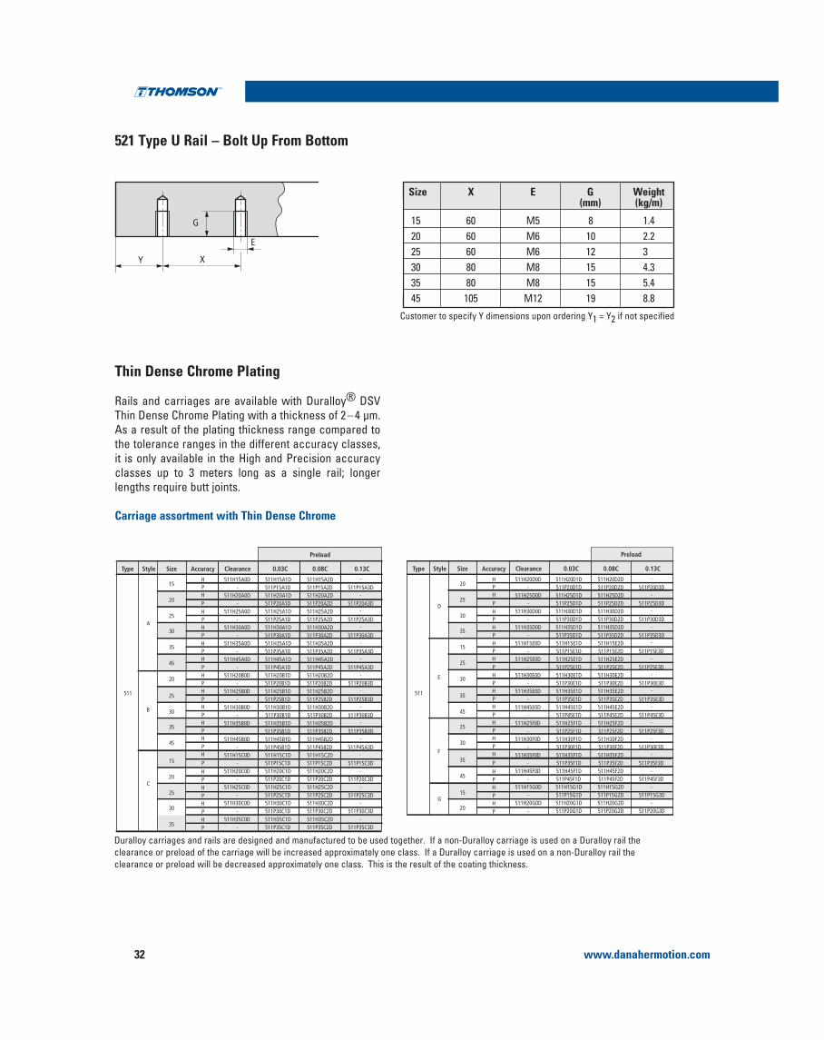
521 Type U Rail – Bolt Up From Bottom
Y X
E
G
Thin Dense Chrome Plating
Rails and carriages are available with Duralloy® DSV Thin Dense Chrome Plating with a thickness of 2 – 4 μm.As a result of the plating thickness range compared to the tolerance ranges in the different accuracy classes, it is only available in the High and Precision accuracy classes up to 3 meters long as a single rail; longer
Carriage assortment with Thin Dense Chrome
Size X E G Weight(mm) (kg/m)
15 60 M5 8 1.420 60 M6 10 2.225 60 M6 12 330 80 M8 15 4.335 80 M8 15 5.445 105 M12 19 8.8
Customer to specify Y dimensions upon ordering Y1 = Y2 if not specified
15HPHPHPHPHPHPHPHPHPHPHPH
PHPHPHP
511H15A0D 511H15A1D- 511P15A1D
511H20A0D 511H20A1D
511H25A0D 511H25A1D- 511P25A1D
- 511P20A1D
511H30A0D 511H30A1D
- 511P35A1D
- 511P30A1D511H35A0D 511H35A1D
511H45A0D 511H45A1D
511H20B0D 511H20B1D- 511P20B1D
- 511P45A1D
511H25B0D 511H25B1D- 511P25B1D
- 511P30B1D511H30B0D 511H30B1D
511H35B0D 511H35B1D- 511P35B1D
511H45B0D 511H45B1D- 511P45B1D
511H15C0D 511H15C1D- 511P15C1D
511H20C0D 511H20C1D- 511P20C1D
511H25C0D 511H25C1D- 511P25C1D
511H30C0D 511H30C1D- 511P30C1D
511H15A2D511P15A2D511H20A2D
511H25A2D511P25A2D
511P20A2D
511H30A2D
511P35A2D
511P30A2D511H35A2D
511H45A2D
511H20B2D511P20B2D
511P45A2D
511H25B2D511P25B2D
511P30B2D511H30B2D
511H35B2D511P35B2D511H45B2D511P45B2D511H15C2D511P15C2D511H20C2D511P20C2D511H25C2D511P25C2D511H30C2D511P30C2D
-
511P15A3D-
-
511P25A3D
511P20A3D
-
511P35A3D
511P30A3D-
-
-
511P20B3D
511P45A3D
-
511P25B3D
511P30B3D
-
-
511P35B3D-
511P45A3D-
511P15C3D-
511P20C3D-
511P25C3D-
511P30C3D
A
B
C
Type Style Size Accuracy Clearance 0.03C 0.08C
Preload
0.13C
20
25
30
15
20
25
30
HP
511H35C0D 511H35C1D- 511P35C1D
511H35C2D511P35C2D
-511P35C3D35
35
45
20
25511
30
35
45
20HPHPHPHPHPHPHPHPHPHPHPH
PHPHPHP
511H20D0D 511H20D1D- 511P20D1D
511H25D0D 511H25D1D
511H30D0D 511H30D1D- 511P30D1D
- 511P25D1D
511H35D0D 511H35D1D
- 511P15E1D
- 511P35D1D511H15E0D 511H15E1D
511H25E0D 511H25E1D
511H30E0D 511H30E1D- 511P30E1D
- 511P25E1D
511H35E0D 511H35E1D- 511P35E1D
- 511P45E1D511H45E0D 511H45E1D
511H25F0D 511H25F1D- 511P25F1D
511H30F0D 511H30F1D- 511P30F1D
511H35F0D 511H35F1D- 511P35F1D
511H45F0D 511H45F1D- 511P45F1D
511H15G0D 511H15G1D- 511P15G1D
511H20G0D 511H20G1D- 511P20G1D
511H20D2D511P20D2D511H25D2D
511H30D2D511P30D2D
511P25D2D
511H35D2D
511P15E2D
511P35D2D511H15E2D
511H25E2D
511H30E2D511P30E2D
511P25E2D
511H35E2D511P35E2D
511P45E2D511H45E2D
511H25F2D511P25F2D511H30F2D511P30F2D511H35F2D511P35F2D511H45F2D511P45F2D511H15G2D511P15G2D511H20G2D511P20G2D
-
511P20D3D-
-
511P30D3D
511P25D3D
-
511P15E3D
511P35D3D-
-
-
511P30E3D
511P25E3D
-
511P35E3D
511P45E3D
-
-
511P25F3D-
511P30F3D-
511P35F3D-
511P45F3D-
511P15G3D-
511P20G3D
D
E
F
G
Type Style Size Accuracy Clearance 0.03C 0.08C
Preload
0.13C
25
30
35
35
45
15
20
15
25
30
35511
45
25
30
Duralloy carriages and rails are designed and manufactured to be used together. If a non-Duralloy carriage is used on a Duralloy rail the clearance or preload of the carriage will be increased approximately one class. If a Duralloy carriage is used on a non-Duralloy rail the clearance or preload will be decreased approximately one class. This is the result of the coating thickness.

www.danahermotion.com 33
Profile Rail Linear Guides 500 Series Ball
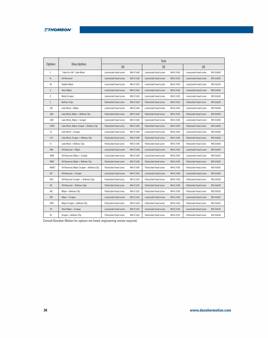
Profile RailModular Accessory Combination Options and Screw Size
M4-0.7x35
M4-0.7x30
M4-0.7x25
M4-0.7x25
M4-0.7x20
M4-0.7x20
M4-0.7x35
M4-0.7x35
M4-0.7x35
M4-0.7x35
M4-0.7x35
M4-0.7x35
M4-0.7x35
M4-0.7x40
M4-0.7x40
M4-0.7x40
M4-0.7x40
M4-0.7x35
M4-0.7x35
M4-0.7x35
M4-0.7x25
M4-0.7x25
M4-0.7x30
M4-0.7x25
M4-0.7x20
Low/socket head screw
Low/socket head screw
Low/socket head screw
Low/socket head screw
Low/socket head screw
Flat/socket head screw
Low/socket head screw
Flat/socket head screw
Low/socket head screw
Flat/socket head screw
Low/socket head screw
Flat/socket head screw
Flat/socket head screw
Low/socket head screw
Low/socket head screw
Flat/socket head screw
Flat/socket head screw
Low/socket head screw
Flat/socket head screw
Flat/socket head screw
Flat/socket head screw
Low/socket head screw
Flat/socket head screw
Low/socket head screw
Flat/socket head screw
M2.5-0.45x25
M2.5-0.45x25
M2.5-0.45x20
M2.5-0.45x20
M2.5-0.45x15
M2.5-0.45x15
M2.5-0.45x30
M2.5-0.45x30
M2.5-0.45x30
M2.5-0.45x30
M2.5-0.45x25
M2.5-0.45x25
M2.5-0.45x25
M2.5-0.45x30
M2.5-0.45x35
M2.5-0.45x30
M2.5-0.45x35
M2.5-0.45x30
M2.5-0.45x30
M2.5-0.45x25
M2.5-0.45x20
M2.5-0.45x25
M2.5-0.45x25
M2.5-0.45x25
M2.5-0.45x15
Low/socket head screw
Low/socket head screw
Low/socket head screw
Low/socket head screw
Low/socket head screw
Flat/socket head screw
Low/socket head screw
Flat/socket head screw
Low/socket head screw
Flat/socket head screw
Low/socket head screw
Flat/socket head screw
Flat/socket head screw
Low/socket head screw
Low/socket head screw
Flat/socket head screw
Flat/socket head screw
Low/socket head screw
Flat/socket head screw
Flat/socket head screw
Flat/socket head screw
Low/socket head screw
Flat/socket head screw
Low/socket head screw
Flat/socket head screw
M2.5-0.45x20
M2.5-0.45x20
M2.5-0.45x20
M2.5-0.45x20
M2.5-0.45x15
M2.5-0.45x15
M2.5-0.45x25
M2.5-0.45x25
M2.5-0.45x25
M2.5-0.45x25
M2.5-0.45x20
M2.5-0.45x20
M2.5-0.45x20
M2.5-0.45x30
M2.5-0.45x30
M2.5-0.45x30
M2.5-0.45x30
M2.5-0.45x25
M2.5-0.45x25
M2.5-0.45x20
M2.5-0.45x20
M2.5-0.45x20
M2.5-0.45x20
M2.5-0.45x20
M2.5-0.45x15
Low/socket head screw
Low/socket head screw
Low/socket head screw
Low/socket head screw
Low/socket head screw
Flat/socket head screw
Low/socket head screw
Flat/socket head screw
Low/socket head screw
Flat/socket head screw
Low/socket head screw
Flat/socket head screw
Flat/socket head screw
Low/socket head screw
Low/socket head screw
Flat/socket head screw
Flat/socket head screw
Low/socket head screw
Flat/socket head screw
Flat/socket head screw
Flat/socket head screw
Low/socket head screw
Flat/socket head screw
Low/socket head screw
Flat/socket head screw
"Lube for Life" Lube Block
Oil Reservoir
Rubber Wiper
Viton Wiper
Metal Scraper
Bellows Clips
Lube Block + Wiper
Lube Block, Wiper + Bellows Clip
Lube Block, Wiper + Scraper
Lube Block, Wiper, Scraper + Bellows Clip
Lube Block + Scraper
Lube Block, Scraper + Bellows Clip
Lube Block + Bellows Clip
Oil Reservoir + Wiper
Oil Reservoir, Wiper + Scraper
Oil Reservoir, Wiper + Bellows Clip
Oil Reservoir, Wiper, Scraper + Bellows Clip
Oil Reservoir + Scraper
Oil Reservoir, Scraper + Bellows Clips
Oil Reservoir + Bellows Clips
Wiper + Bellows Clip
Wiper + Scraper
Wiper, Scraper + Bellows Clip
Viton Wiper + Scraper
Scraper + Bellows Clip
L3
N3
W3
V3
Z3
C3
LW
LWC
LWZ
LWZC
LZ
LZC
LC
NW
NWZ
NWC
NWZC
NZ
NZC
NC
WC
WZ
WZC
VZ
ZC
15DescriptionOption
20 25
Size
1. All fasteners are standard threads.
www.danahermotion.com34
Profile Rail Linear Guides
M4-0.7x45
M4-0.7x35
M4-0.7x30
M4-0.7x30
M4-0.7x25
M4-0.7x25
M4-0.7x45
M4-0.7x45
M4-0.7x45
M4-0.7x45
M4-0.7x45
M4-0.7x45
M4-0.7x45
M4-0.7x45
M4-0.7x45
M4-0.7x45
M4-0.7x50
M4-0.7x40
M4-0.7x40
M4-0.7x40
M4-0.7x30
M4-0.7x30
M4-0.7x30
M4-0.7x30
M4-0.7x25
Low/socket head screw
Low/socket head screw
Low/socket head screw
Low/socket head screw
Low/socket head screw
Flat/socket head screw
Low/socket head screw
Flat/socket head screw
Low/socket head screw
Flat/socket head screw
Low/socket head screw
Flat/socket head screw
Flat/socket head screw
Low/socket head screw
Low/socket head screw
Flat/socket head screw
Flat/socket head screw
Low/socket head screw
Flat/socket head screw
Flat/socket head screw
Flat/socket head screw
Low/socket head screw
Flat/socket head screw
Low/socket head screw
Flat/socket head screw
Low/socket head screw
Low/socket head screw
Low/socket head screw
Low/socket head screw
Low/socket head screw
Flat/socket head screw
Low/socket head screw
Flat/socket head screw
Low/socket head screw
Flat/socket head screw
Low/socket head screw
Flat/socket head screw
Flat/socket head screw
Low/socket head screw
Low/socket head screw
Flat/socket head screw
Flat/socket head screw
Low/socket head screw
Flat/socket head screw
Flat/socket head screw
Flat/socket head screw
Low/socket head screw
Flat/socket head screw
Low/socket head screw
Flat/socket head screw
M5-0.8x50
M5-0.8x45
M5-0.8x35
M5-0.8x35
M5-0.8x30
M5-0.8x30
M5-0.8x50
M5-0.8x50
M5-0.8x50
M5-0.8x50
M5-0.8x50
M5-0.8x50
M5-0.8x50
M5-0.8x50
M5-0.8x55
M5-0.8x55
M5-0.8x55
M5-0.8x45
M5-0.8x50
M5-0.8x50
M5-0.8x35
M5-0.8x35
M5-0.8x35
M5-0.8x35
M5-0.8x30
M4-0.7x40
M4-0.7x30
M4-0.7x25
M4-0.7x25
M4-0.7x20
M4-0.7x20
M4-0.7x40
M4-0.7x40
M4-0.7x40
M4-0.7x40
M4-0.7x40
M4-0.7x40
M4-0.7x40
M4-0.7x40
M4-0.7x40
M4-0.7x40
M4-0.7x45
M4-0.7x35
M4-0.7x35
M4-0.7x35
M4-0.7x25
M4-0.7x25
M4-0.7x30
M4-0.7x25
M4-0.7x20
Low/socket head screw
Low/socket head screw
Low/socket head screw
Low/socket head screw
Low/socket head screw
Flat/socket head screw
Low/socket head screw
Flat/socket head screw
Low/socket head screw
Flat/socket head screw
Low/socket head screw
Flat/socket head screw
Flat/socket head screw
Low/socket head screw
Low/socket head screw
Flat/socket head screw
Flat/socket head screw
Low/socket head screw
Flat/socket head screw
Flat/socket head screw
Flat/socket head screw
Low/socket head screw
Flat/socket head screw
Low/socket head screw
Flat/socket head screw
"Lube for Life" Lube Block
Oil Reservoir
Rubber Wiper
Viton Wiper
Metal Scraper
Bellows Clips
Lube Block + Wiper
Lube Block, Wiper + Bellows Clip
Lube Block, Wiper + Scraper
Lube Block, Wiper, Scraper + Bellows Clip
Lube Block + Scraper
Lube Block, Scraper + Bellows Clip
Lube Block + Bellows Clip
Oil Reservoir + Wiper
Oil Reservoir, Wiper + Scraper
Oil Reservoir, Wiper + Bellows Clip
Oil Reservoir, Wiper, Scraper + Bellows Clip
Oil Reservoir + Scraper
Oil Reservoir, Scraper + Bellows Clips
Oil Reservoir + Bellows Clips
Wiper + Bellows Clip
Wiper + Scraper
Wiper, Scraper + Bellows Clip
Viton Wiper + Scraper
Scraper + Bellows Clip
L
N
W
V
Z
C
LW
LWC
LWZ
LWZC
LZ
LZC
LC
NW
NWZ
NWC
NWZC
NZ
NZC
NC
WC
WZ
WZC
VZ
ZC
DescriptionOption30 35
Size
45

www.danahermotion.com 35
Profile Rail Linear Guides 500 Series Ball
Profile RailModular Accessories
L1
L1
L2
L2
L1
L1
L2
L2
L1 – wiper thickness, L2 – max. screw head stickoutCan be installed without removing carriage from rail
Additional Wiper
Size Rubber Viton® L1 L2 WeightPart No. Part No. (mm) (mm) (kg)
Metal Scraper
L1 – scraper thickness, L2 – max. screw head stickout
Size Scraper L1 L2 WeightPart No. (mm) (mm) (kg)
L1
L1
Oil Reservoir
L1 = Oil reservoir thickness, screw heads are recessed in plate
Size Lubrication L1 WeightPlate (mm) (kg)

www.danahermotion.com36
Profile Rail Linear Guides
Replacement End Cap
2. End cap can be installed without removing carriage from the rail.
Size Style Part No. Style Part No.1 L1(mm) Weight(kg)
15 A, C & G 531EC15 E 531ECH15 8.5 0.004
20 A, B, C, D 531EC20 G 531ECG20 11 0.01
25 A, B, C & D 531EC25 E & F 531ECH25 12.5 0.017
30 A, B, C & D 531EC30 E & F 531ECH30 14 0.023
35 A, B, C & D 531EC35 E & F 531ECH35 16 0.039
45 A & B 531EC45 E & F 531ECH45 19 0.065
511 Size 45 carriage with 531OW and 531WR modular seals on both sides:
1 x 2 = 12.7 x 2
1 x 2 = 7 x 2
2 x 2 = 4 x 2
Total Length = 136.7 mm
Each modular seal is supplied with the proper screws to install
L1
L1
Example
Screws
Stand Offs
Size 15 and 20 Scraper (531ZZ)Size 25 and up Rubber Wiper (531WR)
Spring
MicroPoly® Lube Block
L1 = Lube Block thickness, L2 = max. screw head stickout
L1
L1
L2
L2
packed with EP2 grease and spring is loose for customer to install after assembling carriage on the rail.
Size Lubrication L1 L2 WeightPlate (mm) (mm) (kg)
15 531 LL 15 9.9 4 0.009
20 531 LL 20 11.9 4 0.024
25 531 LL 25 19.5 4 0.083
30 531 LL 30 21.2 4 0.213
35 531 LL 35 24.7 4 0.069
45 531 LL 45 26.9 4 0.123
consult table on page 33 & 34 for proper screw size.
www.danahermotion.com 37
Profile Rail Linear Guides 500 Series Ball
Profile RailBellows Dimensional Information
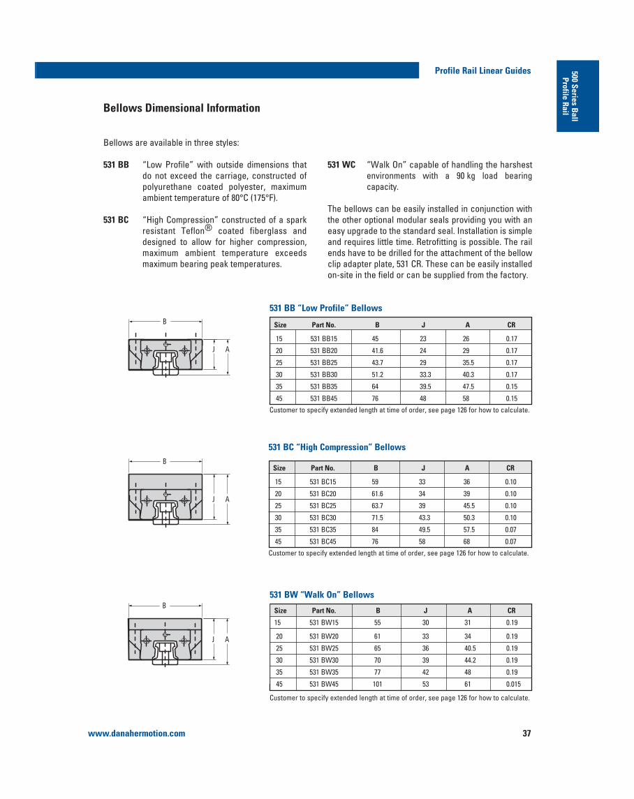
Bellows are available in three styles:
531 BB “Low Profile” with outside dimensions that do not exceed the carriage, constructed of polyurethane coated polyester, maximum
531 BC “High Compression” constructed of a spark resistant Teflon® coated fiberglass and designed to allow for higher compression, maximum ambient temperature exceeds maximum bearing peak temperatures.
B
J A
B
J A
B
J A
531 WCenvironments with a 90 kg load bearing capacity.
The bellows can be easily installed in conjunction with the other optional modular seals providing you with an easy upgrade to the standard seal. Installation is simple
ends have to be drilled for the attachment of the bellow clip adapter plate, 531 CR. These can be easily installed on-site in the field or can be supplied from the factory.
531 BB “Low Profile” Bellows
Size Part No. B J A CR
15 531 BB15 45 23 26 0.17
20 531 BB20 41.6 24 29 0.17
25 531 BB25 43.7 29 35.5 0.17
30 531 BB30 51.2 33.3 40.3 0.17
35 531 BB35 64 39.5 47.5 0.15
45 531 BB45 76 48 58 0.15
Customer to specify extended length at time of order, see page 126 for how to calculate.
531 BC “High Compression” Bellows
Size Part No. B J A CR
15 531 BC15 59 33 36 0.10
20 531 BC20 61.6 34 39 0.10
25 531 BC25 63.7 39 45.5 0.10
30 531 BC30 71.5 43.3 50.3 0.10
35 531 BC35 84 49.5 57.5 0.07
45 531 BC45 76 58 68 0.07
Customer to specify extended length at time of order, see page 126 for how to calculate.
531 BW “Walk On” Bellows
Size Part No. B J A CR
20
Customer to specify extended length at time of order, see page 126 for how to calculate.

www.danahermotion.com38
Profile Rail Linear Guides
Bellow Clip Adapter Plates
The 531 CC Carriage Bellows Clip – Attachment Plate is used to attach the bellows to the carriage. The bellows clip – adapter plate is made of steel.
531 CC Carriage Bellows Clips – Attachment Plate
531 CR Rail Bellows Clips – Attachment Plate
Size Part No.
15 531 CC15
20 531 CC20
25 531 CC25
30 531 CC30
35 531 CC35
45 531 CC45
The 531 CR Rail Bellow Clip – Attachment Plate is used to attach the bellows to the rail. The attaching holes can be drilled in the end of the rail if retrofitting or can be
properly drill end plate clip this results in an area on the end of the rail that will be soft and possibly out of tolerance). The bellows clip – adapter plate is made of steel.
All dimensions in mm, unless otherwise specified.1. Two screws are supplied with each Rail Bellow Clip.2. Min Y dimension to ensure drill depth does not break through rail mounting hole.
Rail End Machine Detail
Rail Machining Detail Screw1
Size Part No.A B C
Depth DepthSize Pitch Length Type
MinY2
Min Max
153 531 CR15 3.50 8.00 7.50 14
20 531 CR20 5.00 8.00 10.00 5.70 7.70 M3 0.5 8 Button 15
25 531 CR25 7.24 10.00 11.50 Head 17
30 531 CR30 9.12 10.00 14.00 7.70 9.70 M4 0.7 10 Cap 20
35 531 CR35 11.00 10.00 17.00 Screw 20
45 531 CR45 15.01 10.00 22.50 22

www.danahermotion.com 39
Profile Rail Linear Guides 500 Series Ball
Profile RailMaintenance and Installation Tools and Accessories
be removed from the rail and then reinstalled to ensure proper installation. It is recommended to leave the car-riage on the assembly rail when it is removed to protect the balls against contamination. If necessary, the two internal mounting screws for fastening runner blocks to the carriage can be tightened to ensure the carriage remains on the assembly rail. The assembly rail is made of plastic.
Standard Rail Plugs and Tape for use with to 500 Series Ball Carriage Type A
Assembly Rail – 531 MT
Part Number Size Length (mm) Weight (kg)
531 MT 15 15 80 0.010
531 MT 20 20 115 0.021
531 MT 25 25 130 0.031
531 MT 30 30 160 0.061
531 MT 35 35 165 0.076
531 MT 45 45 200 0.135
Mylar Tape Size Length
531 RT 15 15 3m
531 RT 20 20 3m
531 RT 25 25 3m
531 RT 30 30 3m
531 RT 35 35 3m
531 RT 45 45 3m
Material: Nylon
Type HP plastic plugs Size
531 HP 15 15
531 HP 20 20
531 HP 25 25
531 HP 30 30
531 HP 35 35
531 HP 45 45
500 Series Rail with Stainless Steel Cover Strip
1. Customer to specify length of rail to be used on at time of order. Delivered piece will be 2 to 3.5 mm longer in order to properly install and fit end caps.
2. Two end caps are supplied with each piece of 531RCS ordered.
Rail Coverstrip Replacement Standard Coverstrip Max Single End Caps Mounting Tool End Caps Coverstrip Rail Width (mm) PC Length (mm)Size Part Number1 Part Number Part Number2 Part Number3
25 531RCS25 531RCT25 531RCP25 521H25C 15 600030 531RCS30 531RCT30 531RCP30 521H30C 19 600035 531RCS35 531RCT35 531RCP35 521H35C 25 600045 531RCS45 531RCT45 531RCP45 521H45C 25 6000
www.danahermotion.com40
Profile Rail Linear Guides
Accuracy Class
A3
H
P1
P1
P1
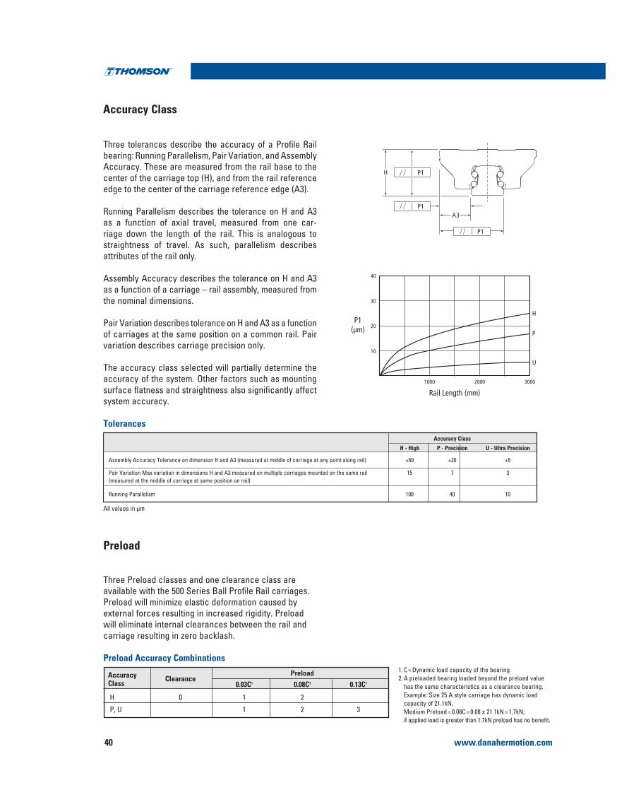
Three tolerances describe the accuracy of a Profile Rail bearing: Running Parallelism, Pair Variation, and Assembly Accuracy. These are measured from the rail base to the
Running Parallelism describes the tolerance on H and A3as a function of axial travel, measured from one car-riage down the length of the rail. This is analogous to straightness of travel. As such, parallelism describes attributes of the rail only.
Assembly Accuracy describes the tolerance on H and A3 as a function of a carriage – rail assembly, measured from the nominal dimensions.
Pair Variation describes tolerance on H and A3 as a functionof carriages at the same position on a common rail. Pair variation describes carriage precision only.
The accuracy class selected will partially determine the accuracy of the system. Other factors such as mounting surface flatness and straightness also significantly affect system accuracy.
Rail Length (mm)
P1(μm) P
H
U
1000
10
20
30
40
2000 3000
Tolerances
1. C = Dynamic load capacity of the bearing2. A preloaded bearing loaded beyond the preload value
has the same characteristics as a clearance bearing.Example: Size 25 A style carriage has dynamic load capacity of 21.1kN, Medium Preload = 0.08C = 0.08 x 21.1kN = 1.7kN;if applied load is greater than 1.7kN preload has no benefit.
Three Preload classes and one clearance class are available with the 500 Series Ball Profile Rail carriages. Preload will minimize elastic deformation caused by external forces resulting in increased rigidity. Preload will eliminate internal clearances between the rail and carriage resulting in zero backlash.
Accuracy ClearancePreload
Class 0.03C1 0.08C1 0.13C1
H 0 1 2
All values in μm
Accuracy Class
H - High P - Precision U - Ultra Precision
Pair Variation Max variation in dimensions H and A3 measured on multiple carriages mounted on the same rail 15 7 3
Running Parallelism 100 40 10
Preload
Preload Accuracy Combinations

www.danahermotion.com 41
Profile Rail Linear Guides 500 Series Ball
Profile RailNOTES :

www.danahermotion.com42
500 Series Roller Profile Rail Linear Guide
Profile Rail Linear Guides
Industry standard dimensions
High load capacities in all directions
High load capacities resulting from large contact surface area between roller and rail
Multiple rail accuracies
Multiple rail mounting hole plugoptions, or rails that mount upfrom underneath are available
Six-runner block attachment bolts per carriage for superior system rigidity
Universal mounting holes – runner blockscan be attached from top or bottom
Both sides of rail are reference edges
Multiple lubrication inlet points, easy field modification
Superior rail straightness as a result of advancedgrinding and straighteningtechnology
Modular accessories for on site upgrade without having to remove the carriagefrom the rail
Low friction double lip seal on allstandard carriages
High rigidity from back-to-back geometry four roller path arrangement
Speeds up to 3m/sAccelerations up to 50 m/s2
Retained rollers when carriage is off the rail and when end cap is removed
Extended standard dowel hole options for rails
Low drag longitudinal seals standard for added protection along rail surface
Corrosion resistance withDuralloy® Thin Dense Chrome plating optional
One piece rail lengths up to 6 meters
Optimized roller path geometries andtransitions for quiet, smooth operation
Multiple carriage designs, accuracies and preloads available
Patented insert moldedrecirculation path resulting in quiet,low noise operation
www.danahermotion.com 43
Profile Rail Linear Guides500 Series Roller
Profile Rail
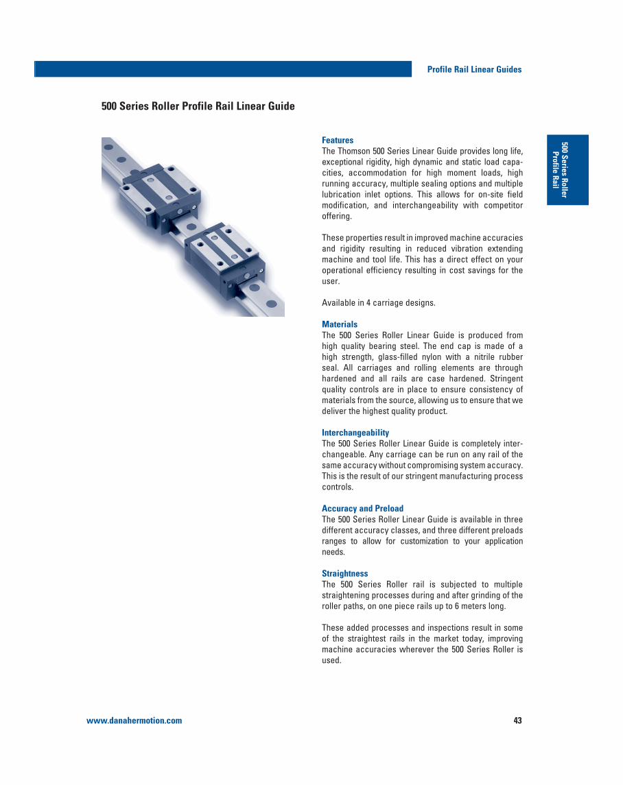
500 Series Roller Profile Rail Linear Guide
FeaturesThe Thomson 500 Series Linear Guide provides long life, exceptional rigidity, high dynamic and static load capa-cities, accommodation for high moment loads, high running accuracy, multiple sealing options and multiple lubrication inlet options. This allows for on-site field modification, and interchangeability with competitor offering.
These properties result in improved machine accuracies and rigidity resulting in reduced vibration extending machine and tool life. This has a direct effect on your operational efficiency resulting in cost savings for the user.
Available in 4 carriage designs.
MaterialsThe 500 Series Roller Linear Guide is produced from
high strength, glass-filled nylon with a nitrile rubber seal. All carriages and rolling elements are through hardened and all rails are case hardened. Stringent
materials from the source, allowing us to ensure that we
InterchangeabilityThe 500 Series Roller Linear Guide is completely inter-changeable. Any carriage can be run on any rail of the same accuracy without compromising system accuracy. This is the result of our stringent manufacturing process controls.
Accuracy and PreloadThe 500 Series Roller Linear Guide is available in three different accuracy classes, and three different preloads ranges to allow for customization to your application needs.
StraightnessThe 500 Series Roller rail is subjected to multiple straightening processes during and after grinding of the roller paths, on one piece rails up to 6 meters long.
These added processes and inspections result in some of the straightest rails in the market today, improving machine accuracies wherever the 500 Series Roller is used.
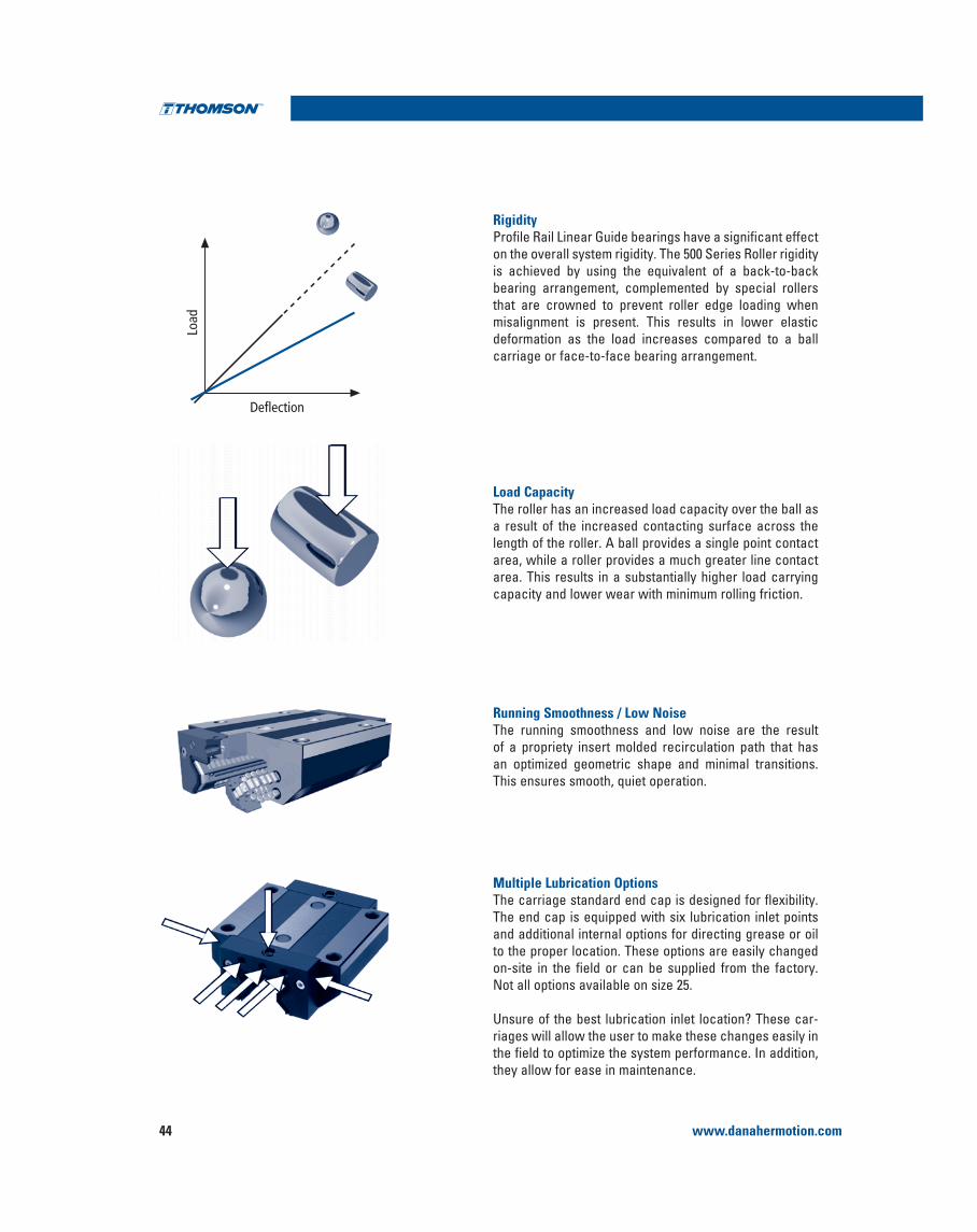
www.danahermotion.com44
Profile Rail Linear Guides
RigidityProfile Rail Linear Guide bearings have a significant effect on the overall system rigidity. The 500 Series Roller rigidity
bearing arrangement, complemented by special rollers that are crowned to prevent roller edge loading when misalignment is present. This results in lower elastic deformation as the load increases compared to a ball carriage or face-to-face bearing arrangement.
Load CapacityThe roller has an increased load capacity over the ball as a result of the increased contacting surface across the length of the roller. A ball provides a single point contact area, while a roller provides a much greater line contact area. This results in a substantially higher load carrying capacity and lower wear with minimum rolling friction.
Running Smoothness / Low NoiseThe running smoothness and low noise are the result of a propriety insert molded recirculation path that has an optimized geometric shape and minimal transitions.
Multiple Lubrication OptionsThe carriage standard end cap is designed for flexibility.
and additional internal options for directing grease or oil to the proper location. These options are easily changed on-site in the field or can be supplied from the factory. Not all options available on size 25.
riages will allow the user to make these changes easily in the field to optimize the system performance. In addition, they allow for ease in maintenance.
Deflection
Load

www.danahermotion.com 45
Profile Rail Linear Guides500 Series Roller
Profile Rail
Modular Accessory OptionsThe carriage is supplied standard with low friction double lip seals and longitudinal seals that completely enclose the bearing carriage to protect the rollers and track surfaces and minimize lubrication loss.
Optional metal scrapers or wiper and oil reservoir components can be easily added on-site in the field or can be supplied assembled from the factory.
These innovative design features allow users to easily, efficiently, and economically upgrade carriage sealing and lubrication without needing to replace the entire carriage assembly.
Longitudinal SealsThe carriage has built-in under carriage low drag longitudinal seals that protect the rollers and roller track surfaces from contamination. These longitudinal seals are an added protection to increase the life and overall performance.
Rail AccessoriesThe rails have multiple options to fill the mounting holes to eliminate possible contamination entry into the bearing. Custom designed plugs are available in plastic, brass, or stainless steel. A special rail is available that utilizes a custom cover strip. In addition, Danaher Motion stocks an assortment of bellows to protect the entire assembly. All options are available from stock and represent another innovative design feature of the 500 Series. Mounting tools for easy and correct installation are available as well.
Retained RollersThe rolling elements of the carriages are retained within the bearing so the carriage can be removed from the rail, or the end cap from the carriage, without worrying about the rollers falling out. It is recommended to place any removed carriage onto a mounting rail or shipping arbor to provide added protection to the rolling elements.

www.danahermotion.com46
500 Series Roller Profile Rail Linear Guide
Profile Rail Linear Guides
Standard end cap assembly foreasy field modification with lubrication channels
Plastic plug (532HP)
Standard rail
Cover strip (532 RCS)and special rail (522 Type C)
Standard end cap (532EC)
Oil reservoir (532OW)
Additional wiper (532WR or VR)
Metal scraper (532ZZ)
Attaching bolts
Grease fitting
The modular, building block design of the 500 Series Roller Profile Rail Linear Guide assembly for easy on-site field
the need for new carriage or rails.
Modular Design Exploded View

www.danahermotion.com 47
Profile Rail Linear Guides500 Series Roller
Profile Rail
Danaher Motion offers four carriage styles with six mountingholes allowing for additional mounting configurations in thefield or retrofitting. All provide superior rigidity and design flexibility.
500 Series Roller Standard Carriages
6000
6000
6000
6000
6000
6000
6000
6000
6000
6000
6000
6000
6000
6000
6000
6000
6000
6000
512P25A1512S25A1512U25A1512P35A1512S35A1512U35A1512P45A1512S45A1512U45A1512P55A1512S55A1512U55A1512P25B1512S25B1512U25B1512P35B1512S35B1512U35B1512P45B1512S45B1512U45B1512P55B1512S55B1512U55B1512P65B1512S65B1512U65B1512P25C1512S25C1512U25C1512P35C1512S35C1512U35C1512P45C1512S45C1512U45C1512P55C1512S55C1512U55C1512P25D1512S25D1512U25D1512P35D1512S35D1512U35D1512P45D1512S45D1512U45D1512P55D1512S55D1512U55D1512P65D1512S65D1512U65D1
PSUPSUPSUPSUPSUPSUPSUPSUPSUPSUPSUPSUPSUPSUPSUPSUPSUPSU
512P25A2512S25A2512U25A2512P35A2512S35A2512U35A2512P45A2512S45A2512U45A2512P55A2512S55A2512U55A2512P25B2512S25B2512U25B2512P35B2512S35B2512U35B2512P45B2512S45B2512U45B2512P55B2512S55B2512U55B2512P65B2512S65B2512U65B2512P25C2512S25C2512U25C2512P35C2512S35C2512U35C2512P45C2512S45C2512U45C2512P55C2512S55C2512U55C2512P25D2512S25D2512U25D2512P35D2512S35D2512U35D2512P45D2512S45D2512U45D2512P55D2512S55D2512U55D2512P65D2512S65D2512U65D2
512P25A3512S25A3512U25A3512P35A3512S35A3512U35A3512P45A3512S45A3512U45A3512P55A3512S55A3512U55A3512P25B3512S25B3512U25B3512P35B3512S35B3512U35B3512P45B3512S45B3512U45B3512P55B3512S55B3512U55B3512P65B3512S65B3512U65B3512P25C3512S25C3512U25C3512P35C3512S35C3512U35C3512P45C3512S45C3512U45C3512P55C3512S55C3512U55C3512P25D3512S25D3512U25D3512S35D3512S35D3512U35D3512P45D3512S45D3512U45D3512P55D3512S55D3512U55D3512P65D3512S65D3512U65D3
522P25A522S25A522U25A522P35A522S35A522U35A522P45A522S45A522U45A522P55A522S55A522U55A522P25A522S25A522U25A522P35A522S35A522U35A522P45A522S45A522U45A522P55A522S55A522U55A522P65A522S65A522U65A522P25A522S25A522U25A522P35A522S35A522U35A522P45A522S45A522U45A522P550A522S55A522U55A522P25A522S25A522U25A522P35A522S35A522U35A522P45A522S45A522U45A522P55A522S55A522U55A522P65A522S65A522U65A
SizeStyle
NarrowHigh
CarriageA
B
CNarrowShort
Carriage
DNarrow
LongCarriage
NarrowHighLong
Carriage
Accuracy0.03C 0.08C
PreloadBasic Part Number
0.13C
Standard RailPart Number
Max. Single PieceRail Length (mm)
25
35
45
55
25
35
45
55
65
25
35
45
55
25
35
45
55
65

www.danahermotion.com48
500 Series Roller Rail Options
Rail Types and AccessoriesThe 500 Series Roller Profile Rail is available in two configurations:
Bolt Down from the top – 522 Type A
The bolt down from the top design has various types of options to plug the holes.
The standard 522 Type A rail mounting holes can be plugged or sealed after installation using the options below.
Plastic Plugs532 HP plastic plugs are an inexpensive and simple method to seal the rail attachment bolt area. The plastic plugs are easy driven in place to any rails with a soft non-metallic drift. They can easily be removed.
Brass Plugs532 HB brass plugs are more rugged than the plastic plug,
installation. They fit in all stand 500 Series Roller Rails and
after installation.
Two-piece Stainless Steel Plugs532 HS two-piece stainless plugs are the most rugged plugs available for the roller rails. The two piece construction and design allows the plugs to lock into place and rest on the top
polishing. The recommended hex head socket must be used to properly install the 532 HS plugs. For correct installation, we recommend use of the 532 HST mounting tools found on page 66.
Mylar TapeA simple and low cost alternative is specialty Mylar tape
Part number 532 RT is available in 3 meter lengths.
Optional 500 Series RailOption 532 RC utilizes a special rail 522 Type C that is easily installed with the 532 RCT mounting tool found on page 66.
Carriage OptionThe 500 Series Roller Profile carriages are also available with special lubrications. They can be ordered directly from stock or with a short lead-time.
Profile Rail Linear Guides
Bolt down from the top – 522 Type A
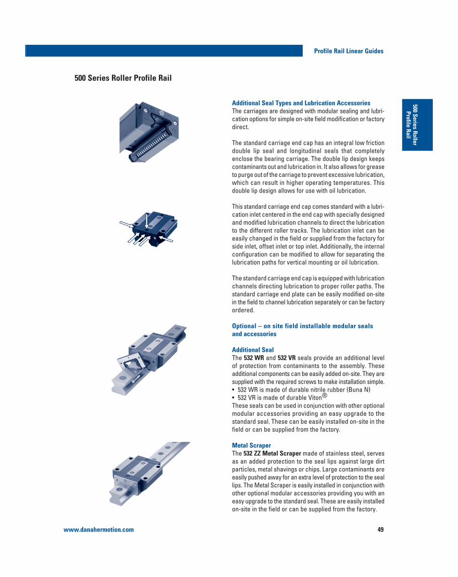
www.danahermotion.com 49
Profile Rail Linear Guides500 Series Roller
Profile Rail
Additional Seal Types and Lubrication AccessoriesThe carriages are designed with modular sealing and lubri-cation options for simple on-site field modification or factorydirect.
The standard carriage end cap has an integral low friction double lip seal and longitudinal seals that completely enclose the bearing carriage. The double lip design keeps contaminants out and lubrication in. It also allows for grease to purge out of the carriage to prevent excessive lubrication, which can result in higher operating temperatures. This double lip design allows for use with oil lubrication.
This standard carriage end cap comes standard with a lubri-cation inlet centered in the end cap with specially designed and modified lubrication channels to direct the lubrication to the different roller tracks. The lubrication inlet can be easily changed in the field or supplied from the factory for side inlet, offset inlet or top inlet. Additionally, the internal configuration can be modified to allow for separating the lubrication paths for vertical mounting or oil lubrication.
channels directing lubrication to proper roller paths. The standard carriage end plate can be easily modified on-site in the field to channel lubrication separately or can be factoryordered.
Optional – on site field installable modular seals and accessories
Additional SealThe 532 WR and 532 VR seals provide an additional level of protection from contaminants to the assembly. These additional components can be easily added on-site. They are
532 VR is made of durable Viton®These seals can be used in conjunction with other optionalmodular accessories providing an easy upgrade to the standard seal. These can be easily installed on-site in the field or can be supplied from the factory.
Metal ScraperThe 532 ZZ Metal Scraper made of stainless steel, serves as an added protection to the seal lips against large dirt particles, metal shavings or chips. Large contaminants are easily pushed away for an extra level of protection to the seal lips. The Metal Scraper is easily installed in conjunction with other optional modular accessories providing you with an easy upgrade to the standard seal. These are easily installed on-site in the field or can be supplied from the factory.
500 Series Roller Profile Rail

www.danahermotion.com50
Profile Rail Linear Guides
Oil ReservoirThe 532 OW Oil Reservoir is a cost effective, automatic lubrication system. It is constructed with an integrated oil reservoir that provides a uniform, consistent lubricating oil to the roller paths for extended periods of time. The
maintenance schedule, assures lubrication gets to the
up to 5000 km of travel.
in conjunction with other optional modular seals for an easy upgrade to the standard seal. These can be easily installed on-site in the field or can be supplied from the factory.
BellowsStandard bellows are available for all assemblies. The bellows cover the entire length of the rail. The bellows are used to provide additional protection against dirt, dust and splashed
is possible when the rail ends are drilled for the attachment of the rail clip 532 CR.
Bellows are available in three styles :
not exceed the carriage
environments with a 90 kg load bearing capacity
The bellow can be easily installed in conjunction with the other optional modular accessories and are an easy upgrade to the standard seal. These can be easily installed on-site in the field.
Note: Additional Modular accessories add additional drag to the carriage assembly resulting in increased start-up friction and power consumption.
Relative Drag Comparison for Design Consideration
Type Relative Drag
Standard carriage
Viton®
For ordering information or for additional
Seal Types and Lubrication Accessories,
see page 62.

www.danahermotion.com 51
Profile Rail Linear Guides500 Series Roller
Profile Rail
StandardSTANDARD OPTIONS
Roller Carriage
500 Series Profile Carriage
Product Type1 Carriage
5 1 2 P 25 A 1 ES1 SMN W ZD
SpecialsSM Special per customer
Extended Standards3
ES1 Offset lubrication in end caps1
ES2 Side lubrication in end caps1
ES3 Top lubrication in end capsES4 ES1 + individual lubrication channels1
ES5 ES2 + individual lubrication channels1
G1 Greased with Mobilux® EP2 G2 Greased with Krytox® GPL227GS Greased per customer specification
Accuracy Class P Precision GradeS Super Precision GradeU Ultra Precision Grade
Size25, 35, 45, 55, 65
Carriage Style A StandardB Standard LongC NarrowD Narrow Long
Preload1 Approximately 0.03 C2 Approximately 0.08 C3 Approximately 0.13 C
Type2 Roller
Accessories2
N Additional Oil Reservoir W Additional Rubber WiperV Additional Viton® WiperZ Metal ScraperC Bellow Clips
Coating OptionD Duralloy® Thin Dense Chrome
(P accuracy only)
1. ES1, ES2, ES4 and ES5 options are available size 35, 45, 55 and 65 only.
2. Accessory combination part numbers are listed from carriage end cap outward. Not all combinations are available. For specific combination availability see page 61 or consult Danaher Motion.
3. Optional inlet and grease options may not be functional with all
to selecting an inlet option review any interference or conflicts with the accessories selected.

www.danahermotion.com52
Profile Rail Linear Guides
StandardSTANDARD STANDARDOPTIONS
Roller Rail
500 Series Profile Rail
Product Type2 Rail
5 2 2 P 25 A D SMDH1
Length (mm) +xxxx Customer Specified RL3000 Stock Length2
RL6000 Stock Length2
SpecialsSM Special per customer print
Machined Options DH1 8mm dowel hole + slot DH2 10mm dowel hole + slot DH3 12mm dowel hole + slot DH4 3/8” dowel hole + slot DH5 1/2” dowel hole + slot JT3 Butt Joint E Bellow Clips Attached
Accuracy Class P Precision Grade S Super Precision Grade U Ultra Precision Grade
Size25, 35, 45, 55, 65
Rail Style A StandardU Bolt up from Bottom C Cover Strip
Coating Option D Duralloy® (P Class only)
Type2 Roller
+xxxx Y= (see note 1)
1. Y = Distance from end of rail to center of first mounting hole, Y1 = Y2unless specified.
2. Stock length rails are considered random length, total length may
customer who will cut to length.
128 for more information and templates.
1. Bellows and rail cover strip must include length at time of order.
calculate bellows length.
Roller Accessories
500 Series Profile Rail
Product Type3 Accessories
5 3 2 EC 25
Size25, 35,
45, 55, 65
Rail Hole Covers and Plugs HP Plastic Rail Plugs HS Stainless Steel 2pc plugs HB Brass Rail Plugs RT Mylar Rail TapeHST HS and HB Installation ToolHSTC Hydraulic Cylinder for HST RCS Rail Cover Strip1
RCT Rail Cover Installation TapeRCP Rail Cover End Cap
Modular Seal/Accessory EC Replacement End Cap WR Rubber WiperVR Viton® WiperZZ Metal Scraper OW Oil Reservoir
Type2 Roller
Mounting Assembly ToolsMT Mounting Rail
BellowsBB Low Profile Bellows1
BC High Compression Bellows1
BW Walk On Bellows1
CC Bellow clips for Carriage CR Bellow clips for Rail

www.danahermotion.com 53
Profile Rail Linear Guides500 Series Roller
Profile Rail
512 Style A and B
500 Series Roller
M1
E
F3
G1
FS2
F3
NB
J P
O
45°
B2 B1
G2
J 1A
G
L 2
Y 2
L 1 L 3 L
X
Y1
L 1 L 2 L 3L
F
512Style A 512
Style B Part Number Location
Reference Edge
N
J1
F1
Y
XS3 Screw
SizeF2
G2
Leng
th
512 Style A – Standard Roller
512 Style B – Standard Long Roller
* Standard tolerance shown, special lower tolerances are available
information.
total length L will increase. Consult page 61-62 for additional information.
Length of rail to be specified at time of order, Y1 = Y2 unless specified otherwise at time of order.
Size Dimensions (mm) RollerA B B1* B2 J J1 L L1 L2 L3 X N S S3 F F1 F2 F3 Ø G G1 G2 M1 O P
±0.05
25 36 70 23 23.5 29.5 24.5 81 45 40 60 30 57 M8 M6 6.8 7 11 11 3.2 9 6.5 13 5.5 7.5 17.5
35 48 100 34 33 40 32 109 62 52 80 40 82 M10 M8 8.5 9 15 15 4.5 12 10 15 7 8 23
45 60 120 45 37.5 50 40 137.5 80 60 104 52.5 100 M12 M12 10.5 14 20 18 5 15 11 21 8 10 30.5
55 70 140 53 43.5 57 48 163.5 95 70 120 60 116 M14 M14 12.5 16 24 20 6 18 13.5 26 9 12 34.5
Size Dimensions (mm) RollerA B B1* B2 J J1 L L1 L2 L3 X N S2 S3 F F1 F2 F3 Ø G G1 G2 M1 O P
±0.05
25 36 70 23 23.5 29.5 24.5 103.4 45 40 79.4 30 57 M8 M6 6.8 7 11 11 3.2 9 6.5 13 5.5 7.5 17.5
35 48 100 34 33 40 32 136 62 52 103 40 82 M10 M8 8.5 9 15 15 4.5 12 10 15 7 8 23
45 60 120 45 37.5 50 40 172.5 80 60 135 52.5 100 M12 M12 10.5 14 20 18 5 15 11 21 8 10 30.5
55 70 140 53 43.5 57 48 205.5 95 70 162 60 116 M14 M14 12.5 16 24 20 6 18 13.5 26 9 12 34.5
65 90 170 63 53.5 76 58 251 110 82 201 75 142 M16 M16 14.5 18 26 23 7 23 19 32 13 15 51
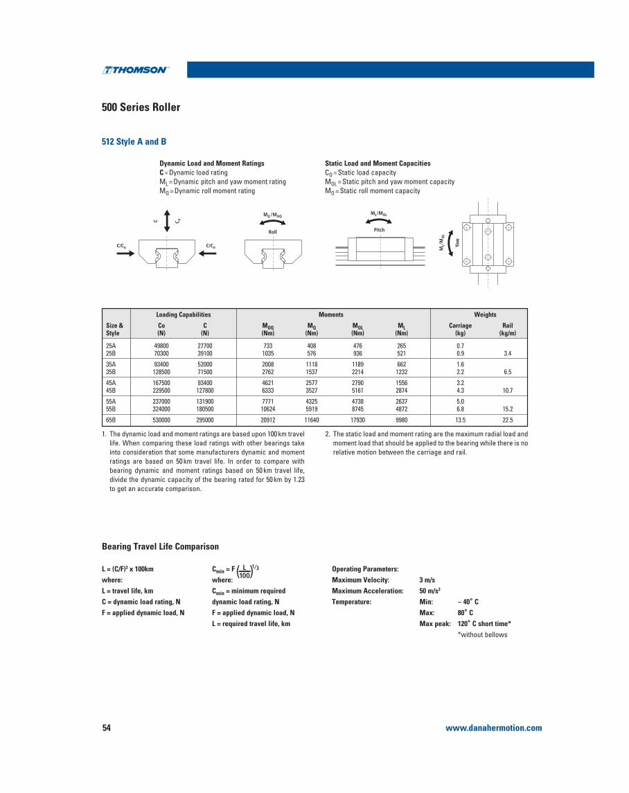
www.danahermotion.com54
500 Series Roller
512 Style A and B
Profile Rail Linear Guides
Dynamic Load and Moment RatingsC = Dynamic load ratingML = Dynamic pitch and yaw moment ratingMQ = Dynamic roll moment rating
Static Load and Moment CapacitiesCO = Static load capacityMOL = Static pitch and yaw moment capacityMO = Static roll moment capacity
C/Co C/Co
C C o
MQ /MOQ
PitchRoll
ML/MOL
Yaw
ML/
MO
L
1. The dynamic load and moment ratings are based upon 100 km travel
into consideration that some manufacturers dynamic and moment ratings are based on 50 km travel life. In order to compare with bearing dynamic and moment ratings based on 50 km travel life, divide the dynamic capacity of the bearing rated for 50 km by 1.23 to get an accurate comparison.
2. The static load and moment rating are the maximum radial load and moment load that should be applied to the bearing while there is no relative motion between the carriage and rail.
Loading Capabilities Moments Weights
Size & Co C MOQ MQ MOL ML Carriage RailStyle (N) (N) (Nm) (Nm) (Nm) (Nm) (kg) (kg/m)
25A 49800 27700 733 408 476 265 0.725B 70300 39100 1035 576 936 521 0.9 3.4
35A 93400 52000 2008 1118 1189 662 1.635B 128500 71500 2762 1537 2214 1232 2.2 6.5
45A 167500 93400 4621 2577 2790 1556 3.245B 229500 127800 6333 3527 5161 2874 4.3 10.7
55A 237000 131900 7771 4325 4738 2637 5.055B 324000 180500 10624 5919 8745 4872 6.8 15.2
65B 530000 295000 20912 11640 17930 9980 13.5 22.5
L = (C/F)3 x 100kmwhere:L = travel life, kmC = dynamic load rating, NF = applied dynamic load, N
Cmin = F ( )L100
1⁄3
where:Cmin = minimum required dynamic load rating, NF = applied dynamic load, NL = required travel life, km
Operating Parameters:Maximum Velocity: 3 m/sMaximum Acceleration: 50 m/s2
Temperature: Min: – 40° CMax: 80° CMax peak: 120° C short time*
*without bellows
Bearing Travel Life Comparison
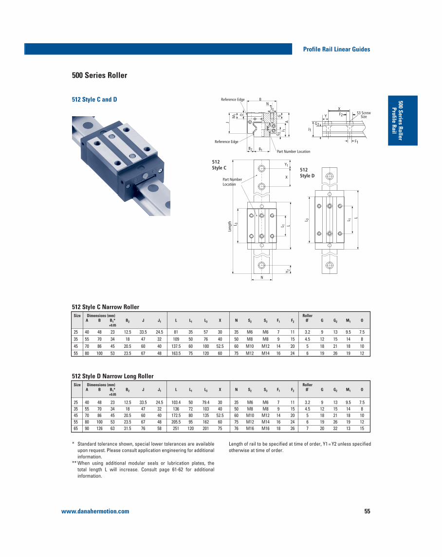
www.danahermotion.com 55
Profile Rail Linear Guides500 Series Roller
Profile Rail
500 Series Roller
512 Style C Narrow Roller
* Standard tolerance shown, special lower tolerances are available
information.
total length L will increase. Consult page 61-62 for additional information.
Length of rail to be specified at time of order, Y1 = Y2 unless specified otherwise at time of order.
512 Style D Narrow Long Roller
M1 O
J
BN
G
AJ 1
G 2
B1B2
Leng
th L 3
Y 2L 1 L
L 3 L 1
L
Reference Edge
Reference Edge
512Style C 512
Style D
Part Number Location
Part Number Location
J1
F1
Y
XS3 Screw
SizeF2
G2
X
Y1
N
S2
512 Style C and D
Size Dimensions (mm) RollerA B B1* B2 J J1 L L1 L3 X N S2 S3 F1 F2 Ø` G G2 M1 O
+0.05
25 40 48 23 12.5 33.5 24.5 81 35 57 30 35 M6 M6 7 11 3.2 9 13 9.5 7.535 55 70 34 18 47 32 109 50 76 40 50 M8 M8 9 15 4.5 12 15 14 845 70 86 45 20.5 60 40 137.5 60 100 52.5 60 M10 M12 14 20 5 18 21 18 1055 80 100 53 23.5 67 48 163.5 75 120 60 75 M12 M14 16 24 6 19 26 19 12
Size Dimensions (mm) RollerA B B1* B2 J J1 L L1 L3 X N S2 S3 F1 F2 Ø` G G2 M1 O
+0.05
25 40 48 23 12.5 33.5 24.5 103.4 50 79.4 30 35 M6 M6 7 11 3.2 9 13 9.5 7.535 55 70 34 18 47 32 136 72 103 40 50 M8 M8 9 15 4.5 12 15 14 845 70 86 45 20.5 60 40 172.5 80 135 52.5 60 M10 M12 14 20 5 18 21 18 1055 80 100 53 23.5 67 48 205.5 95 162 60 75 M12 M14 16 24 6 19 26 19 1265 90 126 63 31.5 76 58 251 120 201 75 76 M16 M16 18 26 7 20 32 13 15
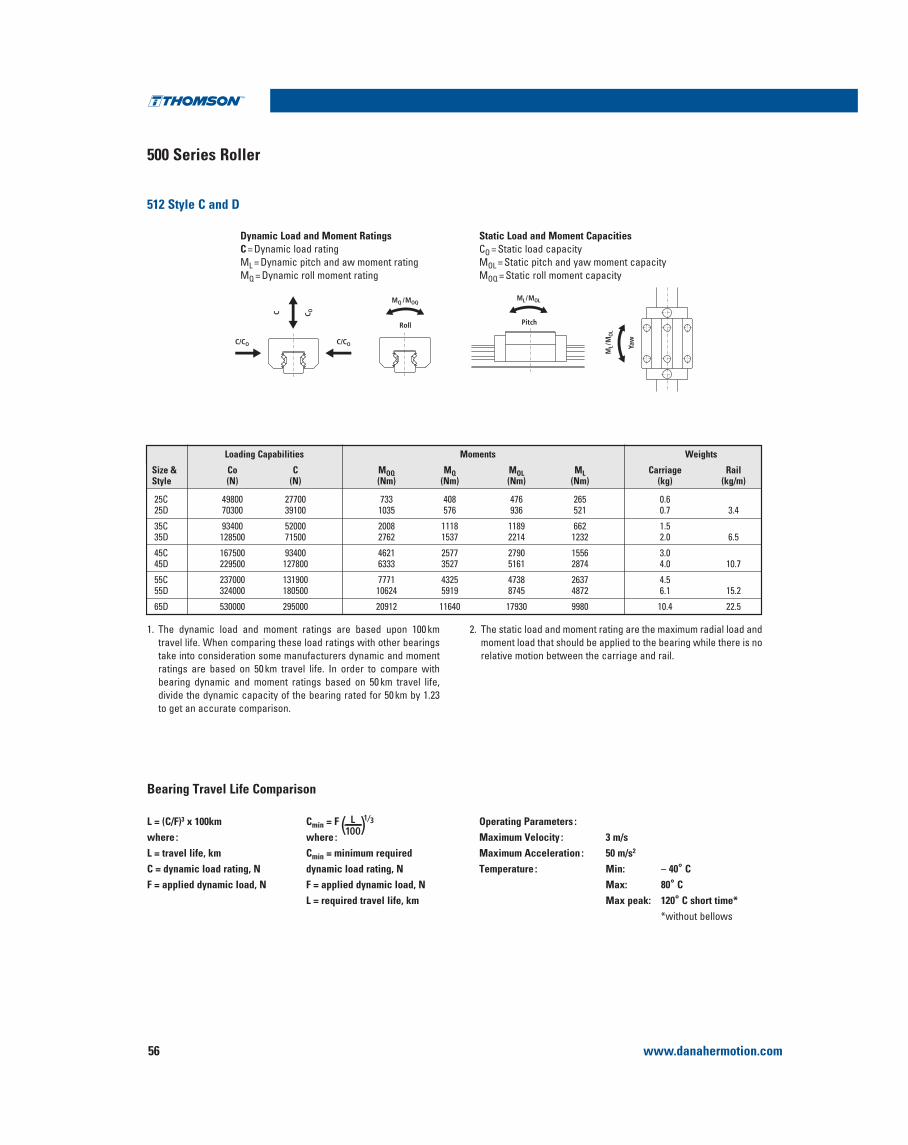
www.danahermotion.com56
500 Series Roller
Profile Rail Linear Guides
L = (C/F)3 x 100kmwhere :L = travel life, kmC = dynamic load rating, NF = applied dynamic load, N
Cmin = F ( )L100
1⁄3
where :Cmin = minimum required dynamic load rating, NF = applied dynamic load, NL = required travel life, km
Operating Parameters :Maximum Velocity : 3 m/sMaximum Acceleration : 50 m/s2
Temperature : Min: – 40° CMax: 80° CMax peak: 120° C short time*
*without bellows
Bearing Travel Life Comparison
512 Style C and D
Dynamic Load and Moment RatingsC = Dynamic load ratingML = Dynamic pitch and aw moment ratingMQ = Dynamic roll moment rating
Static Load and Moment CapacitiesCO = Static load capacityMOL = Static pitch and yaw moment capacityMOQ = Static roll moment capacity
1. The dynamic load and moment ratings are based upon 100 km
take into consideration some manufacturers dynamic and moment ratings are based on 50 km travel life. In order to compare with bearing dynamic and moment ratings based on 50 km travel life, divide the dynamic capacity of the bearing rated for 50 km by 1.23 to get an accurate comparison.
2. The static load and moment rating are the maximum radial load and moment load that should be applied to the bearing while there is no relative motion between the carriage and rail.
C/CO C/CO
C C OMQ /MOQ
PitchRoll
ML/MOL
Yaw
ML/
MO
L
Loading Capabilities Moments Weights
Size & Co C MOQ MQ MOL ML Carriage RailStyle (N) (N) (Nm) (Nm) (Nm) (Nm) (kg) (kg/m)
25C 49800 27700 733 408 476 265 0.625D 70300 39100 1035 576 936 521 0.7 3.4
35C 93400 52000 2008 1118 1189 662 1.535D 128500 71500 2762 1537 2214 1232 2.0 6.5
45C 167500 93400 4621 2577 2790 1556 3.045D 229500 127800 6333 3527 5161 2874 4.0 10.7
55C 237000 131900 7771 4325 4738 2637 4.555D 324000 180500 10624 5919 8745 4872 6.1 15.2
65D 530000 295000 20912 11640 17930 9980 10.4 22.5

www.danahermotion.com 57
Profile Rail Linear Guides500 Series Roller
Profile Rail
The rails can be supplied with dowel holes, radial holes and coaxial holes. Please provide a drawing of your Team can
Rail Modifications
O D - SLIP FIT DOWEL HOLE
LENGTH AS PER CUSTOMER SPECIFICATION
Y1 X (REF) TYP Y2
L1
L3
L2
F
F
G
GC
SECTION F-F
STEP ALLOWEDALL AROUNDSLOTPERIMETER
9.5 MIN
SECTION G-G
Extended Standard Rail Options
522 Type U Rail Bolt Up From Bottom
Maximum Length of Single Piece Rail
Y1 = Y2 unless specified at time of ordering.
Y X
E
G
All dimensions in mm unless otherwise specified.Y1 = Y2 unless otherwise specified.
Option SizeD L1 L2 L3 C
DH1
25
8
15 15
12
11.535 20 20 1745
30 3022.5
55 26.565 31.5
DH2
2535
10
20 20
15
1745
30 3022.5
55 26.565 31.5
DH3
253545
12 30 30 1822.5
55 26.565 31.5
DH4
2535 .787” .787”
.550”
.669”45
1.181” 1.181”.886”
55 1.043”65 1.240”
DH5
25
35
451.181” 1.181” .750”
.886”55 1.043”65 1.240”
+.013-0
+1.5-0
+0.12 +0.40 +0.05
Size (mm) 25 35 45 55 65
Maximum 6000 mmLength
Size X E G Weight (mm) (kg/in)
25 30 M6 12 3.4
35 40 M8 15 6.5
45 52.5 M12 19 10.7
55 60 M14 22 15.2
65 75 M16 25 22.5
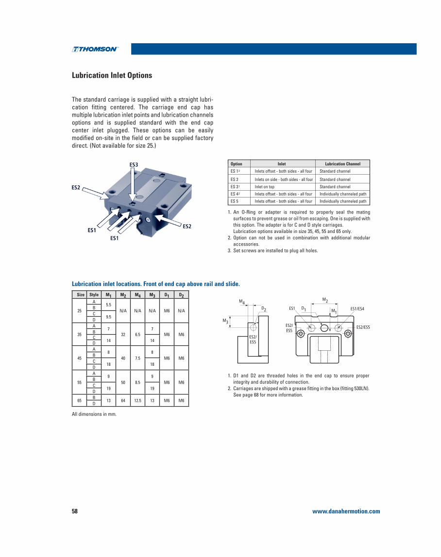
www.danahermotion.com58
Lubrication Inlet Options
The standard carriage is supplied with a straight lubri-cation fitting centered. The carriage end cap has multiple lubrication inlet points and lubrication channels options and is supplied standard with the end cap center inlet plugged. These options can be easily modified on-site in the field or can be supplied factory
Profile Rail Linear Guides
surfaces to prevent grease or oil from escaping. One is supplied with this option. The adapter is for C and D style carriages. Lubrication options available in size 35, 45, 55 and 65 only.
2. Option can not be used in combination with additional modular accessories.
3. Set screws are installed to plug all holes.
Size Style M1 M2 M4 M3 D1 D2
25
A5.5
M6BC
9.5D
35
A7
32 6.57
M6 M6BC
14 14D
45
A8
40 7.58
M6 M6BC
18 18D
55
A9
50 8.59
M6 M6BC
19 19D
65B
13 64 12.5 13 M6 M6D
Lubrication inlet locations. Front of end cap above rail and slide.
D1
ES2/ES5
ES2/ES5
D2
M4
M1
M2
ES2/ES5
ES1
M3
ES1/ES4
1. D1 and D2 are threaded holes in the end cap to ensure proper integrity and durability of connection.
See page 68 for more information.
Option Inlet Lubrication Channel
ES 12 Inlets offset - both sides - all four Standard channel
ES 2 Inlets on side - both sides - all four Standard channel
ES 31 Inlet on top Standard channel
ES 42 Inlets offset - both sides - all four Individually channeled path
ES 5 Inlets offset - both sides - all four Individually channeled path
All dimensions in mm.
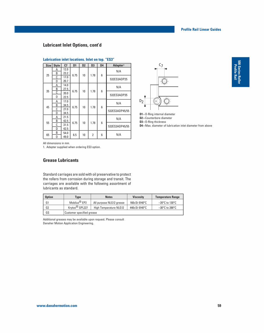
www.danahermotion.com 59
Profile Rail Linear Guides500 Series Roller
Profile Rail
D1 = O-Ring internal diameterD2 = Counterbore diameterD3 = O-Ring thicknessD4 = Max. diameter of lubrication inlet diameter from above
C7
D2
Size Style C7 D1 D2 D3 D4
25
A 12.023.2
6.75 10 1.78 6BC 17.0
20.7D
35
A 14.027.5
6.75 10 1.78 6BC 20.0
22.5D
45
A 17.034.5
6.75 10 1.78 6BC 27.0
34.5D
55
A 21.542.5
6.75 10 1.78 6BC 31.5
42.5D
65B 54.0
49.0 6.5 10 2 6D
Adapter1
532ES3ADP25
532ES3ADP35
Lubrication inlet locations. Inlet on top. “ES3”
Lubricant Inlet Options, cont’d
Standard carriages are sold with oil preservative to protectthe rollers from corrosion during storage and transit. The carriages are available with the following assortment of lubricants as standard.
Danaher Motion Application Engineering.
Grease Lubricants
Option Type Notes Viscosity Temperature Range
G1 Mobilux® EP2 All purpose NLGI2 grease 160cSt @40°C –20°C to 130°C® GPL227 High Temperature NLGI2 440cSt @40°C –30°C to 288°C
GS Customer specified grease
All dimensions in mm.1. Adapter supplied when ordering ES3 option.

www.danahermotion.com60
Thin Dense Chrome Plating
Rails and carriages are available with Duralloy® DSV Thin Dense Chrome Plating with a thickness of 2–4 μm. As a result of the plating thickness range compared to the tolerance ranges in the different accuracy classes, it is only available with Precision accuracy classes up to 3 meters long as a single rail ; long lengths can be butt jointed.
Carriage Assortment with Thin Dense Chrome
Profile Rail Linear Guides
A
B
C
D
Type Style Size Accuracy 0.03C 0.08C
Preload Appropriate
Standard Rail
Max One Piece
Rail Length (mm) 0.13C
512
25 P 512P25A1D 512P25A2D 512P25A3D 522P25AD 3000
35 P 512P35A1D 512P35A2D 512P35A3D 522P35AD 3000
45 P 512P45A1D 512P45A2D 512P45A3D 522P45AD 3000
55 P 512P55A1D 512P55A2D 512P55A3D 522P55AD 3000
25 P 512P25B1D 512P25B2D 512P25B3D 522P25AD 3000
35 P 512P35B1D 512P35B2D 512P35B3D 522P35AD 3000
45 P 512P45B1D 512P45B2D 512P45B3D 522P45AD 3000
55 P 512P55B1D 512P55B2D 512P55B3D 522P55AD 3000
65 P 512P65B1D 512P65B2D 512P65B3D 522P65AD 3000
25 P 512P25C1D 512P25C2D 512P25C3D 522P25AD 3000
35 P 512P35C1D 512P35C2D 512P35C3D 522P35AD 3000
45 P 512P45C1D 512P45C2D 512P45C3D 522P45AD 3000
55 P 512P55C1D 512P55C2D 512P55C3D 522P55AD 3000
25 P 512P25D1D 512P25D2D 512P25D3D 522P25AD 3000
35 P 512P35D1D 512P35D2D 512P35D3D 522P35AD 3000
45 P 512P45D1D 512P45D2D 512P45D3D 522P45AD 3000
55 P 512P55D1D 512P55D2D 512P55D3D 522P55AD 3000
65 P 512P65D1D 512P65D2D 512P65D3D 522P65AD 3000
Note : Duralloy carriages and rails are designed and manufactured to beused together. If a non-Duralloy carriage is used on a Duralloy rail the preload of the carriage will be increased approximately one class.
If a Duralloy carriage is used on a non-Duralloy rail the preload will be decreased approximately one class. This is the result of the coating thickness.

www.danahermotion.com 61
Profile Rail Linear Guides500 Series Roller
Profile Rail
Modular Accessory Combination Options and Screw Size
M4x30
M4x25
M4x25
M4x20
M4x20
M4x40
M4x40
M4x40
M4x40
M4x35
M4x35
M4x35
M4x25
M4x25
M4x25
M4x25
M4x20
M4x35
M4x30
M4x30
M4x25
M4x25
M4x45
M4x45
M4x45
M4x50
M4x40
M4x40
M4x40
M4x30
M4x30
M4x30
M4x30
M4x25
Low/sockethead screw
Low/sockethead screw
Low/sockethead screw
Low/sockethead screw
Flat/sockethead screw
Low/sockethead screw
Low/sockethead screw
Flat/sockethead screw
Flat/sockethead screw
Low/sockethead screw
Flat/sockethead screw
Flat/sockethead screw
Flat/sockethead screw
Low/sockethead screw
Flat/sockethead screw
Low/sockethead screw
Flat/sockethead screw
M5x45
M5x35
M5x35
M5x30
M5x25
M5x50
M5x55
M5x50
M5x55
M5x50
M5x50
M5x50
M5x30
M5x35
M5x35
M5x35
M5x25
Low/sockethead screw
Low/sockethead screw
Low/sockethead screw
Low/sockethead screw
Flat/sockethead screw
Low/sockethead screw
Low/sockethead screw
Flat/sockethead screw
Flat/sockethead screw
Low/sockethead screw
Flat/sockethead screw
Flat/sockethead screw
Flat/sockethead screw
Low/sockethead screw
Flat/sockethead screw
Low/sockethead screw
Flat/sockethead screw
Low/sockethead screw
Low/sockethead screw
Low/sockethead screw
Low/sockethead screw
Flat/sockethead screw
Low/sockethead screw
Low/sockethead screw
Flat/sockethead screw
Flat/sockethead screw
Low/sockethead screw
Flat/sockethead screw
Flat/sockethead screw
Flat/sockethead screw
Low/sockethead screw
Flat/sockethead screw
Low/sockethead screw
Flat/sockethead screw
M6x45
M6x35
M6x35
M6x35
M6x30
M6x55
M6x60
M6x55
M6x60
M6x55
M6x55
M6x55
M6x35
M6x35
M6x35
M6x35
M6x30
Low/sockethead screw
Low/sockethead screw
Low/sockethead screw
Low/sockethead screw
Flat/sockethead screw
Low/sockethead screw
Low/sockethead screw
Flat/sockethead screw
Flat/sockethead screw
Low/sockethead screw
Flat/sockethead screw
Flat/sockethead screw
Flat/sockethead screw
Low/sockethead screw
Flat/sockethead screw
Low/sockethead screw
Flat/sockethead screw
M6x55
M6x40
M6x40
M6x35
M6x35
M6x65
M6x65
M6x65
M6x65
M6x60
M6x60
M6x60
M6x40
M6x40
M6x40
M6x40
M6x35
Low/sockethead screw
Low/sockethead screw
Low/sockethead screw
Low/sockethead screw
Flat/sockethead screw
Low/sockethead screw
Low/sockethead screw
Flat/sockethead screw
Flat/sockethead screw
Low/sockethead screw
Flat/sockethead screw
Flat/sockethead screw
Flat/sockethead screw
Low/sockethead screw
Flat/sockethead screw
Low/sockethead screw
Flat/sockethead screw
Oil Reservoir
Rubber Wiper
Viton Wiper
Metal Scraper
Bellows Clips
Oil Reservoir + Wiper
Oil Reservoir, Wiper + Scraper
Oil Reservoir, Wiper + Bellows Clip
Oil Reservoir, Wiper, Scraper+ Bellows Clip
Oil Reservoir + Scraper
Oil Reservoir, Scraper + Bellows Clips
Oil Reservoir + Bellows Clips
Wiper + Bellows Clip
Wiper + Scraper
Wiper, Scraper + Bellows Clip
Viton Wiper + Scraper
Scraper + Bellows Clip
N3
W3
V3
Z3
C3
NW
NWZ
NWC
NWZC
NZ
NZC
NC
WC
WZ
WZC
VZ
ZC
25DescriptionOption
35 55 6545
Size
1. All fasteners standard thread.2. Consult Danaher Motion for options not listed, engineering review
3. Each modular accessory is supplied with proper screws to install over end cap only and not combinations of modular accessories.

www.danahermotion.com62
Modular Seals and Lubrication Accessories
Profile Rail Linear Guides
Additional Wipers532WR – Rubber Wiper532VR – Viton® Wiper
Metal Scraper532 ZZ
L1 – wiper thickness, L2 – max. screw head stickout
Oil Reservoir532 OW
L2 L1
L2 L1
L2 L1
L2 L1
Size Rubber Viton® L1 L2 Weight Part Number Part Number (mm) (mm) (kg)
L1 = scraper thickness, L2 = max. screw head stickout
Size Part Number L1 (mm) L2 (mm) Weight (kg)
L1 = lubrication plate thickness, screw heads are recessed in plate
Size Lubrication Plate L1 (mm) Weight (kg) L1
L1
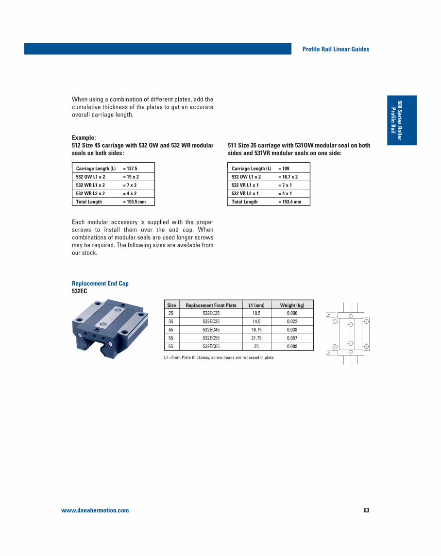
www.danahermotion.com 63
Profile Rail Linear Guides500 Series Roller
Profile Rail
cumulative thickness of the plates to get an accurate overall carriage length.
Example :512 Size 45 carriage with 532 OW and 532 WR modular seals on both sides :
Each modular accessory is supplied with the proper
combinations of modular seals are used longer screws
our stock.
Replacement End Cap532EC
511 Size 35 carriage with 531OW modular seal on both sides and 531VR modular seals on one side:
L 1L 1
Carriage Length (L) = 137.5
532 OW L1 x 2 = 19 x 2
532 WR L1 x 2 = 7 x 2
532 WR L2 x 2 = 4 x 2
Total Length = 193.5 mm
Carriage Length (L) = 109
532 OW L1 x 2 = 16.7 x 2
532 VR L1 x 1 = 7 x 1
532 VR L2 x 1 = 4 x 1
Total Length = 153.4 mm
L1 = Front Plate thickness, screw heads are recessed in plate
Size Replacement Front Plate L1 (mm) Weight (kg)25 532EC25 10.5 0.006
35 532EC35 14.5 0.022
45 532EC45 16.75 0.038
55 532EC55 21.75 0.057
65 532EC65 25 0.089

www.danahermotion.com64
Bellows Dimensional Information
Profile Rail Linear Guides
Bellows are available in three styles:
532 BB “Low Profile” with outside dimensions that do not exceed the carriage, constructed of polyurethane coated polyester, maximum
532 BC “High Compression” constructed of a spark resistant Teflon® coated fiberglass and designed to allow for higher compression, maximum ambient temperature exceeds maximum bearing peak temperatures.
532 BWenvironments with a 90 kg load bearing capacity.
The bellows can be easily installed in conjunction with the other optional modular seals providing you with an easy upgrade to the standard seal. Installation is simple
ends have to be drilled for the attachment of the bellow clip adapter plate, 532 CR. These can be easily installed on-site in the field or can be supplied from the factory.
J A
B
B
J A
B
J A
Customer to specify extended length at time of order, see page 126 for how to calculate.
Customer to specify extended length at time of order, see page 126 for how to calculate.
Size Part No. B J A CR
25 532 BC25 67 40.5 46 0.10
35 532 BC35 90 51.3 57.5 0.07
45 532 BC45 101 61 69 0.07
55 532 BC55 119 68 79 0.06
65 532 BC65 129 75 89 0.06
Customer to specify extended length at time of order, see page 126 for how to calculate.
Size Part No. B J A CR
35
532 BB “ Profile” Bellows
532 BC “High Compression” Bellows
532 BW “Walk On” Bellows
Size Part No. B J A CR
25 532 BB25 47 30.5 36 0.17
35 532 BB35 70 41.3 47.5 0.15
45 532 BB45 81 51 59 0.15
55 532 BB55 99 58 69 0.10
65 532 BB65 109 65 79 0.10

www.danahermotion.com 65
Profile Rail Linear Guides500 Series Roller
Profile Rail
Bellow Clip Adapter Plates
532 CR Rail Bellow Clips – Attachment PlateThe 532 CR Rail Bellow Clip – Attachment Plate is used to attach the bellows to the rail. The attaching holes can be drilled in the end of the rail if retrofitting or can be supplied from the factory. The bellows clip – adapterplate is made of steel.
All dimensions in mm.1. Two screws are supplied with each Rail Bellow Clip.2. Min Y dimension to ensure drill depth does not break through rail mounting hole.
532 CC Carriage Bellow Clips – Attachment PlateThe 532 CC Carriage Bellow Clip – Attachment Plate is used to attach the bellows to the carriage. The bellows clip – adapter plate is made of steel.
Size Part No.
25 532 CC25
35 532 CC35
45 532 CC45
55 532 CC55
65 532 CC65
Rail Machining Detail Screw1
Size Part No.A B C
Depth DepthSize Pitch Length Type
MinY2
Min Max
25 532 CR25 7.24 11.50 12
35 532 CR35 11.00 17.00 20
45 532 CR45 15.01 22.50 22
55 532 CR55 18.01 26.50 24
65 532 CR65 24.00 31.50 28
7.710 9.70 M4 0.70 10.00Button
Head CapScrew
B
A
C
D

www.danahermotion.com66
500 Series Roller Rail Information
Profile Rail Linear Guides
Maintenance and Installation Tools & Accessories :Assembly Rail – 532 MT
removed from the rail and then reinstalled during the installation. It is recommended to leave the carriage on the assembly rail to protect the rollers against con the carriage can be tightened. The assembly rail is made of plastic.
Standard Rail Plugs and Tape
HP plastic plugs
HB brass plugs
HS two-piece stainless steel plugs
Standard RailSize Part Number Length (mm) Weight (kg)25 532 MT25 145 0.062
35 532 MT35 185 0.152
45 532 MT45 230 0.317
55 532 MT55 265 0.525
65 532 MT65 320 0.914
Size Part Number Qty per pack Weight (kg)25 532 HP25 25 .007
35 532 HP35 25 .014
45 532 HP45 25 .025
55 532 HP55 25 .047
65 532 HP65 25 .053
Size Part Number Qty per pack Weight (kg)25 532 HB 25 1 .002
35 532 HB 35 1 .005
45 532 HB 45 1 .008
55 532 HB 55 1 .011
65 532 HB 65 1 .013
Size Part Number Qty per pack Weight (kg)25 532 HS 25 1 set .003
35 532 HS 35 1 set .008
45 532 HS 45 1 set .012
55 532 HS 55 1 set .019
65 532 HS 65 1 set .026

www.danahermotion.com 67
Profile Rail Linear Guides500 Series Roller
Profile Rail
Rail Coverstrip Replacement Standard Coverstrip Max Single End Caps Mounting Tool End Caps Coverstrip Rail Width (mm) PC Length (mm)
Size Part Number1 Part Number Part Number2 Part Number3
25 532RCS25 532RCT25 532RCP25 522P25C 15 6000
35 532RCS35 532RCT35 532RCP35 522P35C 19 6000
45 532RCS45 532RCT45 532RCP45 522P45C 25 6000
55 532RCS55 532RCT55 532RCP55 522P55C 28.5 6000
65 532RCS65 532RCT65 532RCP65 522P65C 32 6000
Mylar tape
HST Stainless Steel and Brass installation tool
1. Customer to specify length of rail to be used on at time of order. Delivered piece will be 2 to 3.5 mm longer in order to properly install and fit end caps.
2. Two end caps are supplied with each piece of 532RCS ordered.3.
accuracy are available.
Optional 500 Series Rail with Stainless Steel Cover Strip
532RCP
532RCT
Size Part Number Length25 532 RT 25 3 m
35 532 RT 35 3 m
45 532 RT 45 3 m
55 532 RT 55 3 m
65 532 RT 65 3 m
1.
532HSTC
Insertion plugincluded with 532HSTxx
532HSTxx
Sliding Block with insertion plug Weight (kg)
532 HST 25 For size 25 rail 2.0
532 HST 35 For size 35 rail 3.5
532 HST 45 For size 45 rail 3.9
532 HST 55 For size 55 rail 5.4
532 HST 65 For size 65 rail 6.5
Hydraulic cylinder (for all sizes) Weight (kg)
532 HSTC1 0.53
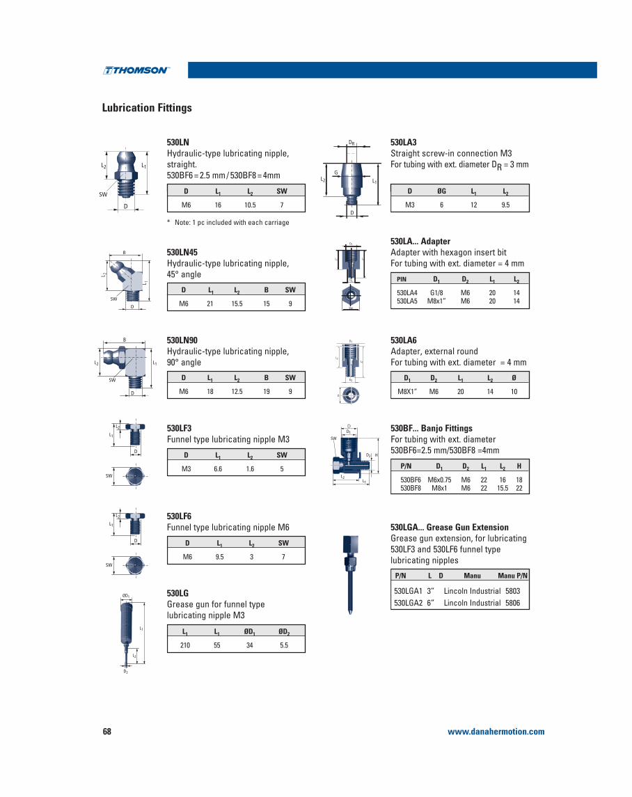
www.danahermotion.com68
Lubrication Fittings
Profile Rail Linear Guides
530LGA... Grease Gun ExtensionGrease gun extension, for lubricating 530LF3 and 530LF6 funnel type lubricating nipples
PIN D1 D2 L1 L2
530LA5 M8x1” M6 20 14
530LA... Adapter Adapter with hexagon insert bitFor tubing with ext. diameter = 4 mm
D ØG L1 L2
M3 6 12 9.5
530LA3Straight screw-in connection M3For tubing with ext. diameter DR = 3 mm
L1 L1 ØD1 ØD2
210 55 34 5.5
530LGGrease gun for funnel type lubricating nipple M3
D L1 L2 SW
M6 9.5 3 7
530LF6Funnel type lubricating nipple M6
D L1 L2 B SW
M6 21 15.5 15 9
530LN45Hydraulic-type lubricating nipple, 45° angle
D L1 L2 SW
M6 16 10.5 7
530LNHydraulic-type lubricating nipple, straight.
D1 D2 L1 L2 Ø
M8X1” M6 20 14 10
530LA6Adapter, external roundFor tubing with ext. diameter = 4 mm
L2 L1
D1
D2
SW
L2 L1
DR
G
D
L2L1
D1
D2
D
D L1 L2 SW
M3 6.6 1.6 5
530LF3Funnel type lubricating nipple M3
ØD1
D2
L2
L1
L 1
B
SW
D
L 2
D
L2 L1
SW
D
L2
L1
SW
D
B
L2 L1
SW D L1 L2 B SW
M6 18 12.5 19 9
530LN90Hydraulic-type lubricating nipple, 90° angle
* Note: 1 pc included with each carriage
P/N L D Manu Manu P/N
530LGA1 3” Lincoln Industrial 5803530LGA2 6” Lincoln Industrial 5806
530BF... Banjo FittingsFor tubing with ext. diameter
P/N D1 D2 L1 L2 H
530BF6 M6x0.75 M6 22 16 18530BF8 M8x1 M6 22 15.5 22
D
L2
L1
SW
D
L2L1
D1
D2 H
SW

www.danahermotion.com 69
Profile Rail Linear Guides500 Series Roller
Profile Rail
Accuracy Class
Three tolerances describe the accuracy of a Profile Rail bearing : Running Parallelism, Pair Variation, and Assembly accuracy. These are measured from the rail
the rail reference edge to the center of the carriage
Running Parallelism describes the tolerance on H and A3 as a function of axial travel, measured from one
analogous to straightness of travel. As such, parallelism describes attributes of the rail only.
Assembly Accuracy [Table 1] describes the tolerance on H and A3 as a function of a carriage – rail assembly, measured from the nominal dimensions.
Pair Variation [Table 1] describes tolerance on H and A3 as a function of carriages at the same position on a common rail. Pair variation describes carriage precision only.
The accuracy class selected will partially determine the accuracy of the system. Other factors such as mounting surface flatness and straightness also significantly affect system accuracy.
Tolerances
A3
H
P1
P1
P1
Rail Length (mm)
P1(m) P
S
U
1000
10
20
30
40
2000 3000
Accuracy ClassP - Precision S - Super Precision U - Ultra Precision
Assembly Accuracy Tolerance
at any point along rail)
Pair Variation Maxvariation in dimensions H and A3 measured on multiple carriages mounted on the 10 5 3
middle of carriage at same position on rail)
Running Parallelism 40 20 10
All values in μm
Preload
Three Preload classes are available with the 500 Series Roller Profile rail carriages. Preload will minimize elastic deformation caused by external forces resulting in increased rigidity.
Preload Accuracy Combinations
1. C = Dynamic load capacity of the bearing
Accuracy PreloadClass 0.03C1 0.08C1 0.13C1

NOTES :

www.danahermotion.com 71
Profile Rail Linear GuidesA
ccuMini
AccuMini Linear Ball Guides
Ultra compact, high roll moment capacity
1. Y= Distance from end of rail to center of 1st mounting hole
Thomson AccuMini Linear Ball Guides offer :
at high speedsA full length integral wiper which protects important bearing from contaminants…effective system life is maximized
momentapplications
reduces system inertia noise
Part Number Description and Specification
1 AD 10 AA A H LXXXX Y= (See Note 1 Below) -XXX AccuMini Assembly
Size: 10, 15, 20
# of Carriages Per Rail
LengthAccuMini AssemblyOptions-A Armoloy Plating-LDS Low Drag Seal-Mxx Special Option
Style DescriptionAA Standard
Accuracy ClassH = High P = Precision
Preload Designation DescriptionA ClearanceB Approx. 0.03 C
CD 10 AA A H -XXX AccuMini Carriage Only
Size: 10, 15, 20
AccuMini CarriageOptions-A Armoloy Plating-LDS Low Drag Seal-Mxx Special Option
Style DescriptionAA Standard
Accuracy ClassH = High P = Precision
Preload Designation DescriptionA ClearanceB Approx. 0.03 C
RD 10 H LXXXX Y= (See Note 1 Below)
AccuMini Rail Only
Size: 10, 15, 20 Length
Accuracy ClassH = High P = Precision
AccuMini Rail

www.danahermotion.com72
AccuMini
AccuMini Linear Guide Series
NOTE :The AccuMini linear guide series carriages do not have retained balls. Removing the carriage from the rail wit-hout an arbor will result in the balls falling out.
(mm)
Size A A1 A2 A3 H H1 H2 B E1 E2 S2 S3 S5 S6
10 26 13 10 8 15 13 9 40 17 20 M2,5 M2,5 3 5,5
15 38 19 15 11,5 21 19 13 58 28 30 M4 M4 4,5 8
20 50 25 20 15 28 25,6 18 76 37 40 M5 M5 5,5 9,5
by customer.
(Miniature Series)Low Profile, Compact Design

www.danahermotion.com 73
Profile Rail Linear GuidesA
ccuMini
Mr, Mro
Mp, Mpo
My, Myo
C, Co
‡ Maximum rail length in one section. Multiple sections can be butt jointed together for longer lengths.
Dynamic Load and Moment RatingsC = Dynamic load ratingMp = Dynamic pitch moment ratingMr = Dynamic roll moment ratingMy = Dynamic yaw moment ratingThe dynamic load and moment ratings are based upona 100 km travel life. In order to compare with bearings rated for 50 km, divide the dynamic capacity of the bea-ring rated for 50 km by 1.26.
Static Load and Moment CapacitiesCo = Static load capacityMpo = Static pitch moment capacityMro = Static roll moment capacityMyo = Static yaw moment capacityThe static load and moment capacities are the maximum radial load and moment load that should be applied to the bearing while there is no relative motion between the carriage and rail.
MASSCarriage Rail
Moment NmRating (lbf-ft)
Load NRating (lbf)
(mm)
Size N3 N6 X L max ‡ C(@100 km) Co Mp, My Mpo, Myo Mr Mro kg kg/m
10 4,5 5,5 25 1500 2820 5300 10 20 15 28 0,045 0,65
15 6 7,5 40 1500 6375 15200 35 66 51 96 0,141 1,42
20 8 9,5 60 3000 11870 23000 75 140 125 235 0,345 2,55
Operating ParametersMaximum Velocity = 3 m/sMaximum Acceleration = 50 m/s2
Maximum Temperature = 80° C
L = (C/F)3 x 100 kmwhere :L = travel life, kmC = dynamic load rating, NF = applied dynamic load, N
Cmin = F ( )L100
1⁄3
where :Cmin = minimum required
dynamic load rating, NF = applied dynamic load, NL = required travel life, km
Bearing Travel Life Comparison
AccuMini Series
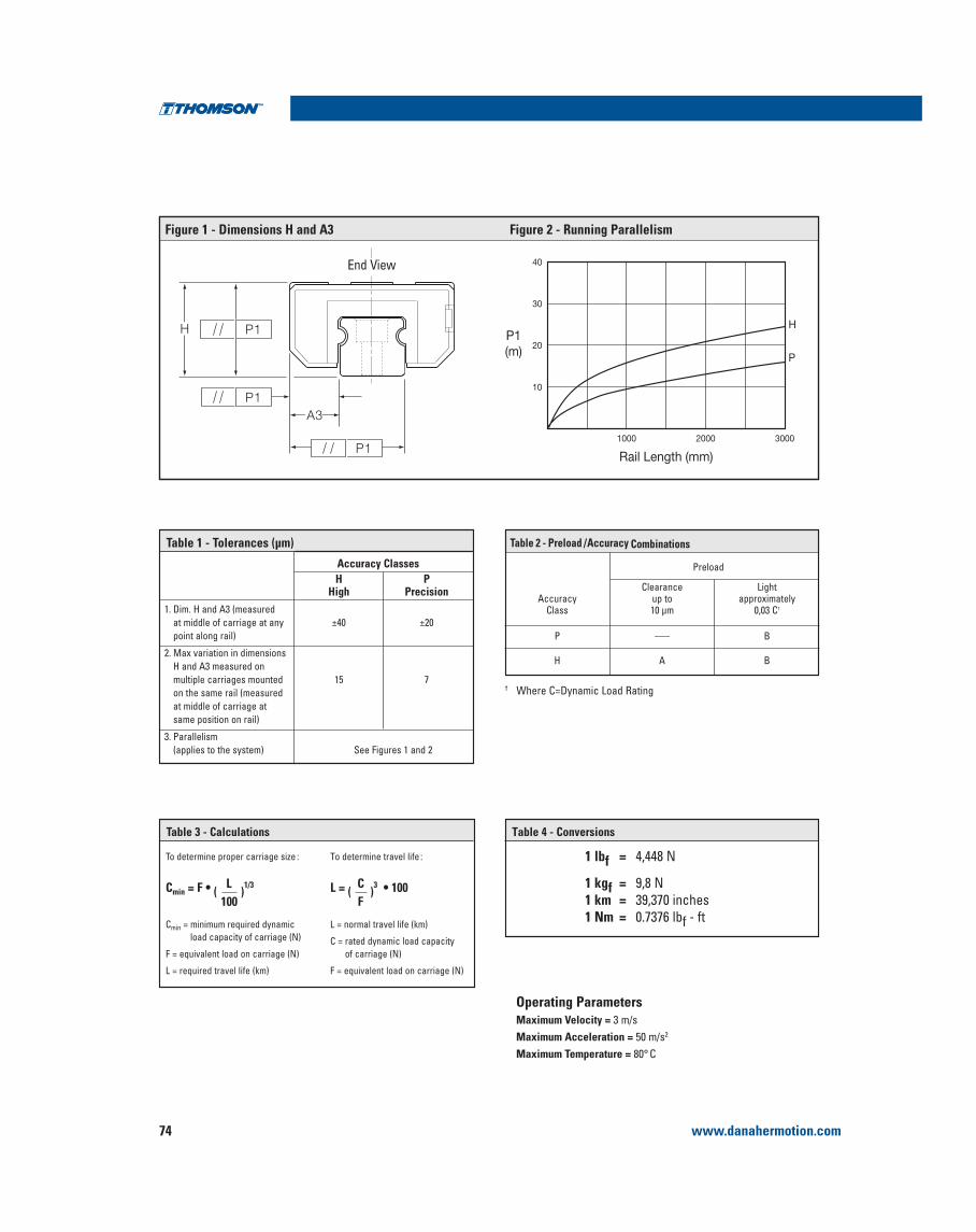
www.danahermotion.com74
Operating ParametersMaximum Velocity =Maximum Acceleration = 2
Maximum Temperature = 80° C
Table 1 - Tolerances (μm)
Accuracy ClassesH P
High Precision
point along rail)
2. Max variation in dimensionsH and A3 measured on multiple carriages mounted 15 7
at middle of carriage atsame position on rail)
3. ParallelismSee Figures 1 and 2
End View
†
Figure 1 - Dimensions H and A3 Figure 2 - Running Parallelism
Table 3 - Calculations
To determine proper carriage size :
Cmin
F
L
To determine travel life :
L
C = rated dynamic load capacity
F
Cmin (L
)1/3
100L = (
C)3
F
Table 2 - Preload /Accuracy Combinations
Clearance Light
Accuracy up to approximatelyClass 10 μm 0,03 C†
P ___ B
H A B
Preload
1 lbf = 4,448 N
1 kgf = 9,8 N1 km = 39,370 inches1 Nm = 0.7376 lbf - ft
Table 4 - Conversions

www.danahermotion.com 75
MicroG
uide
High Moment Load Capacity for single rail/carriage applications
Two track gothic archball groove geometry enablessingle rail application
440 stainless steel construction (little or no lubrication required)
Industry standard,drop-in replacement
Unlimited stroke
One piece rail lengthsover 1 meter
Custom lengthsand configurations
Two styles available(Standard and wide)
High precision accuracy (up to ±0.010mm)
Extremely smoothoperation
Whisper quietmovement
Low Profile
Sizes: 5mm, 7mm*, 9mm, 12mm, 15mm
MicroGuide™ Profile Rail
MicroGuide Part Numbering
Number of Carriages
Types TSR
2 TSR 12 WZ M UU C1 P+350
AccuracyNormal
H HighP Precision
LengthStyle Z Standard WZ Wide
MaterialM Stainless Steel
(standard) Seal Configuration UU Lip Seal Standard
Preload Clearance Fit
C1 Light Preload
Rail and Carriage Size
For more information, or to place an order, please contact your local authorized Thomson™ distributoror Danaher Motion at 1-540-633-3400, Fax: 1-540-633-4162, or E-mail at [email protected].
*For 7mm size, there are only 2 mounting holes per carriage.
Profile Rail Linear Guides

www.danahermotion.com76
MicroGuide™ Profile Rail
MicroGuide™ Profile Rail
W1W2
4 — S xW3
N W
W4
H1
H
L2L1
L3
d2
h
H4Y
d3
X X
TSR-Z Standard
For more information, or to place an order, please contact your local authorized Thomson™ distributoror Danaher Motion at 1-540-633-3400, Fax: 1-540-633-4162, or E-mail at [email protected].
TSR 7, 9, 12, 15Z
TSR 5 Z
MicroGuide™ TSR-Z (Standard)
Longer lengths may be supplied with butt-joints on sizes 7 through 15.
Standard Lengths of Rail
Sizes 5 7 9 12 15
X 15 15 20 25 40Y 5 5 7.5 10 15
StandardLengths
405570100130160
405570851001301000
5575951151351551751952751015
70951201451701952202452703203704701020
1502303104305506701030
Size Assembly Dimensions Carriage Dimensions Rail Dimensions
H H1 N W1 W2 W3 L1 L2 L3 Sx W W4 H4 d2 d3 h Y X
5 6 1.5 3.5 12 8 2 17 12.8 - M2X1.51 5 2.5 4 3.5 2.4 1 5 15
7 8 1.5 5 17 12 2.5 23.5 13.5 8 M2X2.5 7 3.5 4.7 4.2 2.4 2.3 5 15
9 10 2.2 5.5 20 15 2.5 31 20.0 10 M3X3 9 4.5 5.5 6 3.5 3.3 7.5 20
12 13 3 7.5 27 20 3.5 35 20.8 15 M3X3.5 12 6 7.5 6 3.5 4.5 10 25
15 16 4 8.5 32 25 3.5 43 25.7 20 M4X6 15 7.5 9.5 6 3.5 4.5 15 40
(1) For 5mm size, there are only 2 mounting holes per carriage. Note All: Dimensions in mm except where noted otherwise. Longer lengths are availablewith butt joints on sizes 7-15.Sizes in between standards are available, Y dimensions will be the same unless specified at time of ordering.

www.danahermotion.com 77
MicroG
uide
TSR-Z Standard
Static Load and Moment CapacitiesC = Static load ratingMPO = Static pitch moment capacityMYO = Static yaw moment capacityMRO = Static roll moment capacity
Dynamic Loand and Moment RatingsC = Dynamic load rating
MYO
MRO
MPO
C/CO
Load Capacity (N) Moments (Nm) Mass
Size Dynamic C1 Limit Co2 MPO MYO MRO Carriage [kg] Rail [kg/m]
5 336 620 0.8 0.8 1.47 0.01 0.14
7 924 1440 2.55 2.55 5.10 0.02 0.23
9 1544 2360 5.10 5.10 10.4 0.02 0.32
12 2780 4220 8.04 8.72 14.7 0.04 0.58
15 4410 6570 16.5 17.9 30.2 0.07 0.93
Notes:1. The dynamic load and moment ratings are based upon 50km travel life.2. The static load and moment capacities are the maximum radial load and moment load that should be applied to the bearing while there is no relative motion
between the carriage and rail.3. The load limit is the maximum load that may be applied to a system. It is important to analyze the application so that peak and/or shock loads do not exceed
the load limit.
Operating ParametersMaximum Velocity: 3 m/sMaximum Acceleration: 50 m/s
For more information, or to place an order, please contact your local authorized Thomson™ distributoror Danaher Motion at 1-540-633-3400, Fax: 1-540-633-4162, or E-mail at [email protected].
MicroGuide™ Profile Rail
Load/Life Calculations
To determine proper carriage size:
Cmin = F )1/3
Cmin = minimum required dynamicload capacity of carriage (N)
F = equivalent load on carriage (N)
L = required travel life (km)
100L
To determine travel life:
L = )3100
L = normal travel life (km)
C = rated dynamic load capacityof carriage (N)
F = equivalent load on carriage (N)
CF
Profile Rail Linear Guides
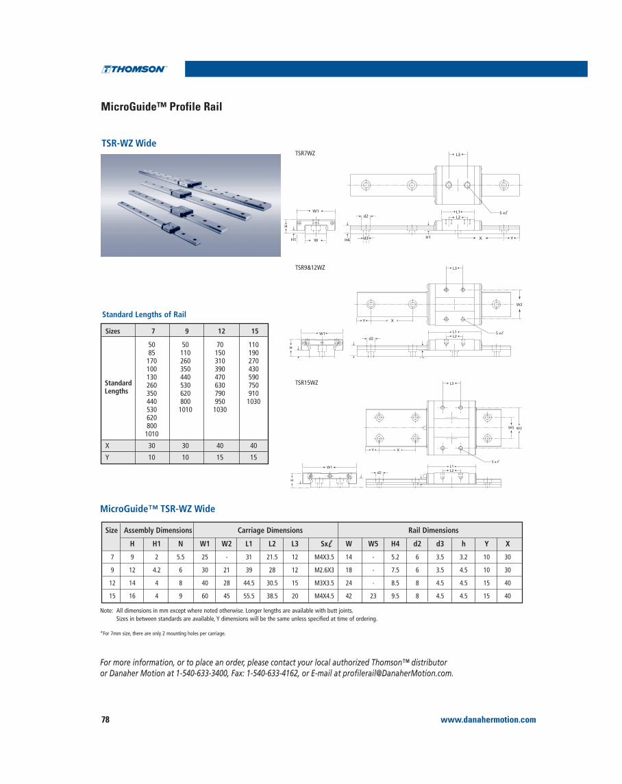
www.danahermotion.com78
TSR-WZ Wide
For more information, or to place an order, please contact your local authorized Thomson™ distributoror Danaher Motion at 1-540-633-3400, Fax: 1-540-633-4162, or E-mail at [email protected].
MicroGuide™ TSR-WZ Wide
Sizes 7 9 12 15
50 50 70 11085 110 150 190170 260 310 270100 350 390 430130 440 470 590260 530 630 750350 620 790 910440 800 950 1030530 1010 10306208001010
X 30 30 40 40
Y 10 10 15 15
StandardLengths
Size Assembly Dimensions Carriage Dimensions Rail Dimensions
H H1 N W1 W2 L1 L2 L3 Sx W W5 H4 d2 d3 h Y X
7 9 2 5.5 25 - 31 21.5 12 M4X3.5 14 - 5.2 6 3.5 3.2 10 30
9 12 4.2 6 30 21 39 28 12 M2.6X3 18 - 7.5 6 3.5 4.5 10 30
12 14 4 8 40 28 44.5 30.5 15 M3X3.5 24 - 8.5 8 4.5 4.5 15 40
15 16 4 9 60 45 55.5 38.5 20 M4X4.5 42 23 9.5 8 4.5 4.5 15 40
Note: All dimensions in mm except where noted otherwise. Longer lengths are available with butt joints. Sizes in between standards are available, Y dimensions will be the same unless specified at time of ordering.
*For 7mm size, there are only 2 mounting holes per carriage.
Standard Lengths of Rail
L3
L2L1
d2S x W1
W
H
H1 H4 d3 YXH1
L3
S x L2L1
W2
XY
H
W1d2
d3 H1
L3
W5
S x L1L2
XY
W1
H
d2
W2
TSR7WZ
TSR9&12WZ
TSR15WZ
MicroGuide™ Profile Rail

www.danahermotion.com 79
MicroG
uide
Static Load and Moment CapacitiesC = Static load ratingMPO = Static pitch moment capacityMYO = Static yaw moment capacityMRO = Static roll moment capacity
Dynamic Load and Moment RatingsC = Dynamic load rating
MROMPO
C/COMYO
Load Capacity (N) Moments (Nm) Mass
Size Dynamic C1 Limit Co2 MPO MYO MRO Carriage [kg] Rail [kg/m]
7 1370 2160 5.39 5.39 15.2 0.03 0.51
9 2450 3920 16.3 16.3 36.0 0.04 1.08
12 4020 6080 17.2 18.6 47.6 0.08 1.5
15 6660 9800 35.2 38.2 137 0.17 3.0
Notes:1. The dynamic load and moment ratings are based upon 50 km travel life.2. The static load and moment capacities are the maximum radial load and moment load that should be applied to the bearing while there is no relative motion
between the carriage and rail.3. The load limit is the maximum load that may be applied to a system. It is important to analyze the application so that peak and/or shock loads do not exceed
the load limit.
Operating ParametersMaximum Velocity: 3 m/sMaximum Acceleration: 50 m/s2
For more information, or to place an order, please contact your local authorized Thomson™ distributoror Danaher Motion at 1-540-633-3400, Fax: 1-540-633-4162, or E-mail at [email protected].
Load/Life Calculations
To determine proper carriage size:
Cmin = F )1/3
Cmin = minimum required dynamicload capacity of carriage (N)
F = equivalent load on carriage (N)
L = required travel life (km)
100L
To determine travel life:
L = )3100
L = normal travel life (km)
C = rated dynamic load capacityof carriage (N)
F = equivalent load on carriage (N)
CF
TSR-WZ Wide
MicroGuide™ Profile Rail
Profile Rail Linear Guides

www.danahermotion.com80
PrecisionP
N
H
C
B
A D
DatumPlane
25
20
15
10
5
Run
ning
Par
alle
lism
Length of Rail L(mm)
Normal
High
Precision
200 400 600
Δ C
and
Δ D
(μm
)
Dimensional Tolerance
Pair Tolerance
DimensionalTolerance
Pair Tolerance
Normal(blank)
Accuracy ofeach part
Series Type,Size, and Style
TSR5 Z
TSR7 Z
TSR9 Z
TSR12 Z
TSR15 Z
0~+1.5
±2
±2
±3
±5
-1.5~0
-3~0
-4~0
-6~0
-10~0
HighH
Radial Clearances (μm)clearance fit (blank) light preload C1
25
20
15
10
5
Run
ning
Par
alle
lism
Length of Rail L(mm)
Normal
High
Precision
200 400 600
Δ C
and
Δ D
(μm
)
Series Type,Size, and Style
TSR7 WZ
TSR9 WZ
TSR12 WZ
TSR15 WZ
±2
±2
±3
±5
-3~0
-4~0
-6~0
-10~0
Radial Clearances (μm)clearance fit (blank) light preload C1
Normal(blank)
PrecisionP
HeightH
WidthN
N
H
C
B
A D
DatumPlane
Dimensional Tolerance
Pair Tolerance
DimensionalTolerance
Pair Tolerance
Accuracy ofeach part
HeightH
WidthN
TSR WZ
±0.040
0.030
±0.040
0.030
±0.020
0.015
±0.025
0.020
±0.010
0.007
±0.015
0.010
Normal(blank)
PrecisionP
HighH
±0.030
0.015
±0.030
0.015
±0.015
0.005
±0.015
0.005
±0.040
0.030
±0.040
0.030
±0.020
0.015
±0.025
0.020
±0.010
0.007
±0.015
0.010
TSR7 Z, TSR9 Z, TSR12 Z & TSR15 ZTSR5 Z
TSR-Z (Standard) Accuracy Tolerance
For more information, or to place an order, please contact your local authorized Thomson™ distributoror Danaher Motion at 1-540-633-3400, Fax: 1-540-633-4162, or E-mail at [email protected].
TSR-Z (Standard) Running Parallelism
Accuracy ToleranceRunning Parallelism
TSR-WZ (Wide) Running Parallelism
TSR-Z (Standard) Fit Up
TSR-WZ (Wide) Fit Up
MicroGuide™ Profile Rail

www.danahermotion.com 81
MicroG
uide
For more information, or to place an order, please contact your local authorized Thomson™ distributoror Danaher Motion at 1-540-633-3400, Fax: 1-540-633-4162, or E-mail at [email protected].
Standard Lengths of Rail Load/Life Calculations
Sizes 7 WZ 9 WZ 12 WZ 15 WZ
X 30 30 40 40Y 10 10 15 15
Standard Lengths
50110170260350440530620800
1010
50110170260350440530620800
1010
70150230310390470630790950
1030
1101902704305907509101030
To determine proper carriage size:
Cmin = F ( ) 1/3
Cmin = minimum required dynamic load capacity of carriage (N)
F = equivalent load on carriage (N)
L = required travel life (km)
50L
To determine travel life:
L = ( ) 3
L = normal travel life (km)
C = rated dynamic load capacity of carriage (N)
F = equivalent load on carriage (N)
CF
1 lbf = 4.448 N
1 kgf = 9.8 N
Maximum Travel Speed: Vmax = 3 m/sMaximum Acceleration: amax = 50 m/s2
1 km = 39,370 inches
1 Nm = 0.7376 lbf - ft
Conversions
Z for standard styleWZ for wide style
M for stainless steel(standard)
UU for end seals only(standard)
(blank) for clearance fitC1 for light preload
(blank) for normal gradeH for high grade
P for precision grade
How To Order
MicroGuide™ Profile Rail
Profile Rail Linear Guides