damage analysis of the stratified curved plate
TRANSCRIPT

JOURNAL OF MATERIALS AND ENGINEERING STRUCTURES 5 (2018) 223–236 223
Research Paper
Damage analysis of the stratified curved plate
Mohamed Saad a,b,*, Djamel Ouinas b aLaboratoire de Technologie Industrielle, Département de Génie Mécanique, Université de Tiaret, BP 78, Route de Zaaroura, Tiaret, Algérie bLaboratoire de Modelisation Numérique et Expérimentale des phénomènes Mécanique, Université Ibn Badis de Mostaganem, 2700 Mostaganem, Algerie
A R T I C L E I N F O
Article history :
Received : 14 January 2018
Revised : 23 May 2018
Accepted : 28 May 2018
Keywords:
Damage
Fiber rupture
Matrix crack
Delamination
A B S T R A C T
This paper deals with numerical analysis of dynamic behavior of a curvilinear graphite / epoxy composite shell under the effect of different impact loads at low speeds. Damage is assumed to initiate when one of Hashin’s failure criteria is satisfied, and its evolution is modeled by Mindlin’s Formulation with geometric non-linearity. This has been accomplished by developing a user defined subroutine and implementing it in the FE software ABAQUS. From strains supplied by ABAQUS the material subroutine uses a micromechanics approach based on the method of cells and values of material parameters of constituents to calculate average stresses in an FE, and checks for Hashin’s failure criteria. If damage has initiated in the material, the subroutine evaluates the damage developed, computes resulting stresses, and provides them to ABAQUS. The computed time histories of the impact loads acting are found to agree well with the numerical ones available in the literature, and various damage and failure modes agree qualitatively with those observed in tests.
1 Introduction
Rarely, damage caused by low velocity impact are detected with the naked eye. Since they cannot be found, the harm caused by low velocity impact in composite materials are considered potentially hazardous [1]. In general, the cracking of the matrix and fiber breakage are the initial damage prior to delamination. The stiffness of the damaged material and therefore the structure can be significantly reduced by damage [2, 3]. This loss of stiffness may even cause a catastrophic failure. For these reasons, it is important to develop tools that enable analysis of structures of composite materials under low velocity impact. However, the most commonly used composite materials suffer from certain important limitations. Among these, the most important is possibly their response to a localized impact [4].
* Corresponding author. E-mail address: [email protected] e-ISSN: 2170-127X,

224 JOURNAL OF MATERIALS AND ENGINEERING STRUCTURES 5 (2018) 223–236
Since components made of composite materials are generally very susceptible to transverse impacts, it is essential to characterize the response of these materials to such a type of loading in order to be able to predict the behavior of the components in service [5-8]. Thus the peculiarity of the composite materials is that they can damage themselves internally without leaving a visible trace of the defect, especially during small shocks which can lead to significant losses of material properties [9-12]. Indeed, materials such as carbon / epoxy, commonly used, have a linear elastic response until rupture [13]. This fragile behavior makes composite structures vulnerable to impact which is identified as the most critical loading mode for composite materials for these reasons these materials must then satisfy expensive certification procedures for low-speed impacts [14]. If internal damage resulting from a shock is not detected and repaired over time, the damage area will continually grow and ultimately lead to structural collapse. The presence of these defects is therefore taken into account in the dimensioning of structures [15]. The impact event generally causes cracking of the matrix, breaking of fibers and delamination within the structure. Therefore, it is necessary to investigate the impact damage and the failure mode as well as the continuous monitoring of the structure in order to avoid any major incident and catastrophic failure. It is important to know the impact response strength, the impact energy absorbed by the material before it fails to produce an effective design for a structure [16]. Moreover, the behavior of composites to shocks remains difficult to predict. This leads manufacturers to undertake often expensive tests in order to determine the response to crashes and impacts of complex structures and to understand the phenomena of damage involved. The reduction of the number of tests necessarily involves a fine understanding of these Physical phenomena as well as the development of finite element models of damage [17].
The numerical analysis of damage caused by low velocity impact has been made mainly by the finite element method (FEM). Lakshminarayana and murthy, [18, 19] made a dynamic analysis of a structure using a commercial program to predict damage to the material without regard to the progressive failure analysis aid. Zhao and Cho, [20] analyzed the onset of damage in a composite material using 8 noded shell elements. Ganapathy and Rao, [21] analyzed the damage in a laminated curved shell element using a double curvature of 48 degrees of freedom. Li et al. [22-23], presented a numerical model to simulate the process of low velocity impact based on a Mindlin plate element of 9 nodes. Sahli et al, [24], Presents a dynamic formulation of the boundary element method for stress and failure criterion analyses of anisotropic thin plates.
In this paper, a numerical analysis of a curvilinear shell is studied to predict the evolution damage in the various layers of the structure under different low speeds impact loads and different thicknesses of the folds of the structure
2 Element Development
This analysis is based on the theory of linear elasticity. The fiber and matrix materials in each layer are considered to be homogeneous. Consequently, the equation of equilibrium of a composite shell and an impact system at an instant t can be expressed by the general dynamic equation [25]:
[ ]{ } [ ]{ } { }M d k d F+ = (1)
Where: [ ]M Is the matrix of mass, [ ]K the rigidity matrix, [ ]F the force, [ ]d the displacement vector, d the acceleration
vector.
In our case the only load is the contact force caused by the impactor, it’s a force defined by a scalar acting perpendicular to the plate at the point of contact and having an amplitude equal to the contact force. The contact force vector is defined by:
{ } { }F f U= (2)
Where: U is a unit vector and f the effective force vector.
At time t + Δt, the equation is written as follows:
[ ]{ } [ ]{ } { }t t t t t tM d k d F+∆ +∆ +∆+ = (3)
Where : [ ]k is the effective stiffness matrix
JOURNAL OF MATERIALS AND ENGINEERING STRUCTURES 5 (2018) 223–236 225
The Newmark method is used to obtain the solution of this equation. Consequently, the speed and acceleration vectors at time t + Δt are written by:
{ } { } { } { }(1 )t t t t t t
d d t d t dλ λ+∆ +∆
= + − ∆ + ∆ (4)
{ } { } { }
{ } { }
2 2(1/ ) (1/ )
- (1/ t (1/ (1/ 2 )
t t t t t
tt
d t d t d
d d
β β
β β β
+∆ +∆= ∆ − ∆
∆ − −
(5)
The parameters β and λ are constants.
Substituting equation (5) in equation (3), we obtain:
{ } { }t tt tk d F+∆+∆ = (6)
With: [ ] [ ]2(1/ )k t M kβ = ∆ + (7)
{ } { }t t t t tF J F+∆ +∆ = + (8)
Where: { } [ ]{ }
( ){ }
2(1/ )
(1 2 ) / 2
tt
t
t dJ M
d
β
β β
∆ = + −
(9)
At the moment t t+ ∆ equation (1) can be written as:
{ } { }t t t tF f U+∆ +∆= (10)
During the loading and discharging phases the contact force is
1.5( )t t t tf k α+∆ +∆= For loading (11)
1.5
0
0
t tt t
mm
f fα αα α
+∆+∆ −
= −
For discharging (12)
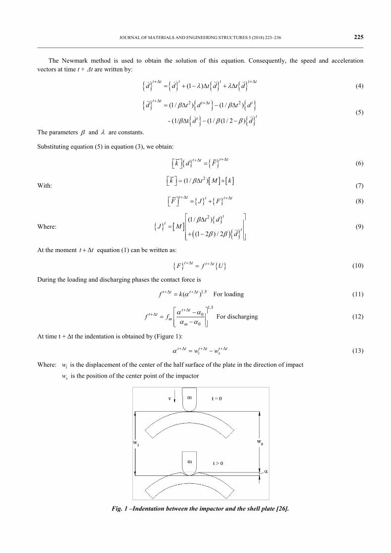
At time t + Δt the indentation is obtained by (Figure 1):
t t t t t ti sw wα +∆ +∆ +∆= − (13)
Where: iw is the displacement of the center of the half surface of the plate in the direction of impact
sw is the position of the center point of the impactor
Fig. 1 –Indentation between the impactor and the shell plate [26].

226 JOURNAL OF MATERIALS AND ENGINEERING STRUCTURES 5 (2018) 223–236
3 Damage Criteria
Impact damage, such as Fiber fracture, matrix cracking or delamination, can in fact lead to a reduction in the residual behavior of composite structures even in the absence of a visible mark on the surface [27]. Among the large families of the most breaking representatie and used, the Tsai-Wu criteria, which generally leads to an underestimation of the breaking force, the Hashin criterion which is characterized by a relative simplicity of the expressions following Mode of rupture, which allows easy use. In addition, it takes into account physical considerations and finally the criterion of stress and maximum deformation.
To predict Fiber fracture, cracks in the matrix and the delamination of a graphite / epoxy composite material, we were interested in the Hashin damage criterion, which is a mathematical expression linking the actual stresses in the material to the ultimate constraints supported by the latter. When this criterion is exceeded, the integrity property of the material no longer exists and there is local ruin of the medium. Hashin [28] proposes a criterion that takes into account all these constraints on the resin. Moreover, it distinguishes the state of traction in the matrix from the state of compression. In the case of traction in the transverse direction of the fold, the criterion is written:
2 2 2 2
22 33 23 22 33 12 132 2 2
( )1
MNT MS FS
σ σ σ σ σ σ σσ σ σ+ + +
+ + ≥ (14)
In the case of compression in the transverse direction, the criterion becomes:
2 2 2 2 2
22 33 22 33 23 22 33 12 132 2 2
( ) ( )1 1
2 4MNC
MS MNC MS MS FS
σ σ σ σ σ σ σ σ σ σσ σ σ σ σ
+ + − + − + + + ≥
(15)
With:
MNTσ : Resistance of the matrix in traction
MNCσ : Resistance of the matrix to compression
MSσ : Resistance of shear of matrix
FSσ : Resistance of the fiber in traction
Thus the criterion of damage to the fibers by traction proposed by Hashin ( 11 0σ > )
2 212 1311
212
1 Failure 1 No FailuretX S
σ σσ >++ = ≤
(16)
There are many criteria of quadratic form for detecting the appearance of delamination. Overall, the authors propose criteria involving transverse constraints, namely 13σ , 23σ and 33σ . Some do not differentiate the state of compression stress from that of the traction in the normal direction to the ply. Hashin, for example, proposes a criterion where he does not take into account the sign of 33σ :
2 2
233 12 13212
( ) 1DN Sσ σ σσ
++ > (17)
DNσ is the resistance of the lamina to a normal force, and 12S is the resistance of the lamina to shear delamination.
In numerical analysis, after a failure of a lamina [29], it results the determination of degradation properties through their laws, to date, there is no universally accepted approach of the properties and stiffness reduction factors to be used after the failure of a lamina. If there is a traction failure in the direction 2 of a unidirectional laminate (Figure 2), there are researchers that make the properties E2 and ν12 null. The degradation laws may vary depending on the material and the arrangement of the fibers. The simplest, but not very realistic, degradation hypothesis is the total degradation of the mechanical properties of a layer upon failure.
JOURNAL OF MATERIALS AND ENGINEERING STRUCTURES 5 (2018) 223–236 227
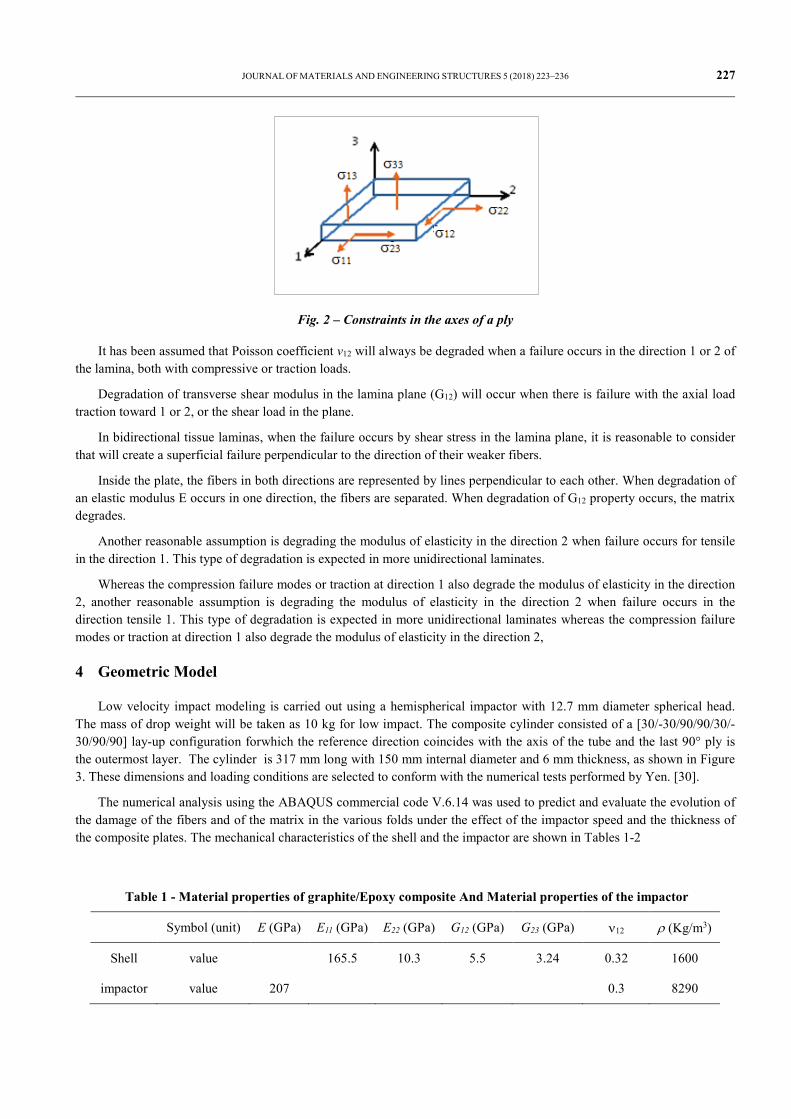
Fig. 2 – Constraints in the axes of a ply
It has been assumed that Poisson coefficient ν12 will always be degraded when a failure occurs in the direction 1 or 2 of the lamina, both with compressive or traction loads.
Degradation of transverse shear modulus in the lamina plane (G12) will occur when there is failure with the axial load traction toward 1 or 2, or the shear load in the plane.
In bidirectional tissue laminas, when the failure occurs by shear stress in the lamina plane, it is reasonable to consider that will create a superficial failure perpendicular to the direction of their weaker fibers.
Inside the plate, the fibers in both directions are represented by lines perpendicular to each other. When degradation of an elastic modulus E occurs in one direction, the fibers are separated. When degradation of G12 property occurs, the matrix degrades.
Another reasonable assumption is degrading the modulus of elasticity in the direction 2 when failure occurs for tensile in the direction 1. This type of degradation is expected in more unidirectional laminates.
Whereas the compression failure modes or traction at direction 1 also degrade the modulus of elasticity in the direction 2, another reasonable assumption is degrading the modulus of elasticity in the direction 2 when failure occurs in the direction tensile 1. This type of degradation is expected in more unidirectional laminates whereas the compression failure modes or traction at direction 1 also degrade the modulus of elasticity in the direction 2,
4 Geometric Model
Low velocity impact modeling is carried out using a hemispherical impactor with 12.7 mm diameter spherical head. The mass of drop weight will be taken as 10 kg for low impact. The composite cylinder consisted of a [30/-30/90/90/30/-30/90/90] lay-up configuration forwhich the reference direction coincides with the axis of the tube and the last 90° ply is the outermost layer. The cylinder is 317 mm long with 150 mm internal diameter and 6 mm thickness, as shown in Figure 3. These dimensions and loading conditions are selected to conform with the numerical tests performed by Yen. [30].
The numerical analysis using the ABAQUS commercial code V.6.14 was used to predict and evaluate the evolution of the damage of the fibers and of the matrix in the various folds under the effect of the impactor speed and the thickness of the composite plates. The mechanical characteristics of the shell and the impactor are shown in Tables 1-2
Table 1 - Material properties of graphite/Epoxy composite And Material properties of the impactor
Symbol (unit) E (GPa) E11 (GPa) E22 (GPa) G12 (GPa) G23 (GPa) ν12 ρ (Kg/m3)
Shell value 165.5 10.3 5.5 3.24 0.32 1600
impactor value 207 0.3 8290

228 JOURNAL OF MATERIALS AND ENGINEERING STRUCTURES 5 (2018) 223–236
Table 2 – stress values of graphite/epoxy
Symbol (unit) 1tS (GPa) 1
cS (GPa) 2tS (GPa) 12S (GPa) 2
cS (GPa) 23S (GPa)
value 2.55 1.5 0.04 0.12 0.14 0.07
Fig. 3 – Geometry of cylinder and the impactor
In this work, the discretization process is performed by subdividing the cylinder into distinct finite elements as. To get more accurate results, a fine grid size has been applied in the regions located near the impact center (i.e. high deformation region) while gradually large grid sizes were used away from impact area as shown.
When choosing the mesh type, the set-up time and the computational expenses were considered. Analyzing different mesh scales was required to decide what will be the appropriate mesh density until two meshes gave nearly the same results, then the mesh was considered adequate and used in the analysis.
The present cylinder material is an orthotropic elastic type, therefore, it is recommended that a 4-node quadrilateral layered shell element. The cylinder section was meshed with 18144 elements and 19708 nodes. These types of elements are used in explicit dynamic analyses and have bending and membrane capabilities with both in-plane and normal loads permitted. The solid steel impactor is modeled using 6485 elements. The impactor is modeled as a rigid material.
5 Failure consideration
The implementation procedure for describing the behavior of the composite was inspired by detecting scheme for impact damaged of the composite figure 4 used by Kim [31].
The initiation and propagation of matrix cracks and delamination are very complicated. In this work, under the following assumptions, matrix cracking and delamination are considered in the macroscopic sense.
1. The initial mode of impact induced damage is intraply matrix cracks.
2. Delamination initiates from these matrix cracks and propagates along the interfaces of layers with different fiber orientations.
6.35mm
317.5mm
127mm

JOURNAL OF MATERIALS AND ENGINEERING STRUCTURES 5 (2018) 223–236 229
Fig. 4 – Detecting scheme for impact-induced damaged. [31]
6 Results and Discussion
6.1 Validation Model
Impact force is a very important parameter in the prediction of structure damage under drop weight impact. Its variation with time is essential for prediction of damage. As a result, the computed contact force histories were compared to the numerical contact force results of Yen et al. [30]. Figures 5 and 6 show the impact load vs. time for velocities of 1.195 m/s and 1.548 m/s , respectively
0.000 0.003 0.006 0.009 0.012 0.0150
500
1000
1500
impa
ct lo
ad (N
)
Time (S)
Yen's model present model
Fig. 5 – FE code validation at Vf = 1.195 m/s
Yes
No
Start
M ; K Assembly
t = 0
Calculate impact
Initial matrix cracking
Delamination
Store
t = end t
Stop
t = t+∆t
No
Yes

230 JOURNAL OF MATERIALS AND ENGINEERING STRUCTURES 5 (2018) 223–236
0.000 0.003 0.006 0.009 0.012 0.0150
200
400
600
800
1000
1200
impa
ct lo
ad (N
)
Time (s)
Yen's FEM model Present model
Fig. 6 – FE code validation at Vf = 1.548 m/s
For both velocities, excellent agreement was found between Yen’s numerical model results and the present FE model results having similar curve morphology for impact load-time plots with differences within numerical approximation. Within this time range, the analyses provide approximately the same frequencies and peak-to-peak magnitudes. This correlation validates the model and supports the use of the chosen contact model. Therefore, the modified FE model will be applied to the problem at hand which consists on investigating the behavior of a composite cylinder under low velocity impact. The analysis will include also the quantification of damage to the pipe structure as well as a cylinder wall thickness effects.
6.2 Prediction of the damage of the folds of the structure under the effect of the speed
In order to evaluate the effect of the speed of the impactor on the prediction and the evolution of the damage, four different values (3m / s, 6m / s, 12m / s and 15m / s) were considered with hemispherical impactor of radius of 12.7 mm.
Figure 7 shows the variation of the impact force with respect to the time obtained for an impact velocity of 3 m/s. The curve shows two peaks during the loading of the impact event. These two peaks, which occurred at t = 0.4 and 1.5 ms, are the indications of triggering the damage of the matrix and the fibers due to the compressive deformation which absorbs (at the beginning of the damage) the large.
0 2 4 6 8 10 12 14 16 18 200
200
400
600
800
impa
ct fo
rce
(N)
impact time (m,s)
Fig. 7 – Variation of the impact force for the impact velocity of 3 m / s.

JOURNAL OF MATERIALS AND ENGINEERING STRUCTURES 5 (2018) 223–236 231
Fig. 8 – Evolution of damage in the folds for the speed of 3m / s
Proportion of the impact energy. Figure 8 shows the evolution of the damage in the folds as a function of time for the speed of 3 m / s and indicates that the cracking of the matrix begins approximately (t = 0.0004 sec) in layers 1, 2 , 7 and 8 followed by similar damage in layers 3 and 4 while no cracks are detected on layers 5 and 6. This is mainly due to the fact that the bending stress is closer to the center of the target. The cracking of the matrix in the layers (7 and 8) is caused by compression, while the tension stress produces cracks in lower layers (1 and 2). Delamination begins at the same time with matrix cracking
The beginning of fiber rupture occurred on the outer layer (8) at t = 1.5 to 1.9 m.s. This is probably caused by high compression forces.
From the results of the force-time curve of Figure 9, for the impact velocity of 6 m / s, the first appreciable variation in the load is at approximately 0.5 m.s. We also note that more the speed of impact increases more the impact load is maximal. Figure 10 indicates that for this rate cracking of the matrix begins approximately at (t = 0.0006 sec) on layers 1, 7 and 8, followed by similar damage on layers 2, 4 and 6, while no cracking occurs Produced on layers 3 and 5. As the impact time increases (t = 1.8 ms), the cracking of the matrix propagates on layers 1 and 4. Fiber fracture triggering occurred Later between t = 0.0019 and 0.0023 sec on the inner layer and between t = 0.0019 and 0.0026 sec on the outer layers.
0 2 4 6 8 10 12 14 16 18 200
200
400
600
800
1000
1200
impa
ct fo
rce
(N)
impact time (m,s)
Fig. 9 – Variation of the impact force for the impact velocity of 6 m / s
0 1 2 3 4 5 6 7 8 9 100
1
2
3
4
5
6
7
8
laye
r N°
Temps d'impact (m.s)
delamination matrix crack fiber rupture

232 JOURNAL OF MATERIALS AND ENGINEERING STRUCTURES 5 (2018) 223–236
0 2 4 6 8 10 120
1
2
3
4
5
6
7
8
laye
r N°
impact time (m.s)
delamination matrix crack fiber rupture
Fig. 10 – Evolution of the damage in the folds for the speed of 6 m / s
The load-time curve obtained under the impact velocity of 12 m / s is shown in Figures 11 and 12 indicates that for a higher impact velocity of 12 m / s, cracking of the matrix begins at about (t = 0.0006 sec) on layers 1, 7 and 8, followed by similar damage on layers 2, 4, 5 and 6 while no cracking occurred on the layer 3.
0 2 4 6 8 10 12 14 16 18 200
200
400
600
800
1000
1200
1400
impa
ct fo
rce
(N)
impact time (m,s)
Fig. 11 – Variation of the impact force for the impact velocity of 12 m / s
Fig. 12 – Evolution of the damage in the folds for the speed of 12m / s
0 1 2 3 4 5 6 7 8 9 10 11 120
1
2
3
4
5
6
7
8
laye
r N°
impact time (m.s)
delamination matrix crack fiber rupture

JOURNAL OF MATERIALS AND ENGINEERING STRUCTURES 5 (2018) 223–236 233
More the time of impact increases (t = 0.0015 sec), more the matrix crack propagates on the layer 1. The delamination started at the same time with Matrix cracking. Fiber fracture occurred later between t = 0.0016 and 0.0021 sec on the inner and outer layers
The curve of Figure 13 shows the variation of the contact force as a function of the impact time for the speed 15 m / s. According to the curves of Figure 14, the matrix cracking initiated at about t = 0.0006 sec on the layers 1 and 8, followed by similar damage on the layers 2, 3, 4, 5, 6 and 7. The rupture trigger of fiber occurred later between t = 0.0018 and 0.0023 sec on the inner and outer layers. The severity of the fiber failure gradually increased towards the inner and outer layers of the laminate. It should be mentioned that the impactor could penetrate the shell.
0 2 4 6 8 10 12 14 16 18 200
200
400
600
800
1000
1200
1400
impa
ct fo
rce
(N)
impact time (m,s)
Fig. 13 – Variation of the impact force for the impact velocity of 15 m / s
0 1 2 3 4 5 6 7 8 9 10 11 12 13 140
1
2
3
4
5
6
7
8
laye
rN°
impact time (m.s)
delamination matrix crack fiber rupture
Fig. 14 – Evolution of the damage in the folds for the speed of 15 m / s
6.3 Prediction of the damage of the folds of the structure
The load-time curve obtained under the effect of the thickness of the ply of 0.25 mm is shown in figure 15. These results show that for 0.25mm, the first significant decrease in the charge occurred at 0.0004 sec. Figure 16 shows that for the thickness 0.25 mm, the cracking of the matrix begins at t = 0.4 ms on layers 1 and 8, followed by similar damage on layers 2, 3, 4 and 7 while no cracking Is noticed on layers 5 and 6. Fiber fracture occurred later between t = 0.0017 and 0.0038 sec on the outer layers. The fiber break progression gradually increases towards the outer layers of the laminate.
The load-time curve obtained under the effect of the thickness of 0.375 mm is shown in figure 17. These results show that for this thickness, the first significant decrease in the charge occurred approximately at 0.0006 s.

234 JOURNAL OF MATERIALS AND ENGINEERING STRUCTURES 5 (2018) 223–236
0 2 4 6 8 10 12 14 16 18 200
200
400
600
800
1000
impa
ct fo
rce
(N)
impact time (m,s)
Fig. 15 – Variation of the impact force for the thickness 0.25 mm
Fig. 16 – Evolution of the damage in the folds for the thickness 0.25 mm
Fig. 17 – Variation of the impact force for the thickness 0.375 mm
Figure 18 shows that for the 0.375 m, cracking of the matrix begins at t = 0.0006 sec on layers 1, 2, 7 and 8, followed by similar damage on layers 3, 4 and 6 while no cracking occur on layer 5. Fiber fracture occurred later between t = 0.0039 and 0.0062 sec on the inner layer and between t = 0.0018 and 0.0042 sec on the outer layer.
0 2 4 6 8 10 120
1
2
3
4
5
6
7
8
laye
r N°
impact time (m.s)
delamination matrix crack fiber rupture
0 2 4 6 8 10 12 14 16 18 200
200
400
600
800
1000
1200
1400
impa
ct fo
rce
(N)
impact time (m,s)

JOURNAL OF MATERIALS AND ENGINEERING STRUCTURES 5 (2018) 223–236 235
Fig. 18 – Evolution of the damage in the folds for the thickness 0.25 mm
7 Conclusions
In front of the increasing use of composite structures, the development of reliable structural and mechanical characterization tools has become an important scientific and technological challenge. Indeed, the precise knowledge of the mechanical properties of the constituents, their morphology and their arrangement as well as the precise measurement of the effective properties of the composite materials are necessary conditions for solving a major problem linking the overall behavior to the microstructure. Moreover, the evolution of the effective properties as a function of the conditions of use can allow the characterization of the damage of these materials, in order to optimize their use and to evaluate their service life.
In this work we have studied an example of an impact problem on a multi-layer curvilinear shell made of carbon/epoxy composites using a cylindrical impactor. The model of the example studies the structural behavior of the shell under the effect of low impact velocity. The contact forces and the damage of the matrix and the fibers were obtained for different impact speeds (3, 6, 12 and 15 m/s) and for different wall thicknesses (0.25 and 0.375 mm) with the code ABAQUS v.14.6.
In the curves of the contact force as a function of the impact time exhibit peaks during the loading event, indicating the triggering of the mode of matrix and fiber damage. Due to continuous loading and beyond the maximum point of the curve, there is a continuous progression of fiber damage which increases with increasing impact velocity up to the time where there is permanent damage caused to the structure and thus to the reduction of the impact force. Damage by the small 0.25mm thickness occurred earlier and was more serious than the thickness of 0,375mm
REFERENCES
[1]- C.T. Sun, S. Chattopadhyay, Dynamic response of anisotropic laminated plates under initial stress to impact of a mass. J. Appl. Mech. 42(3) (1975) 693-698. doi:10.1115/1.3423664
[2]- N.H. Tai, M.C. Yip, J.L. Lin, Effects of low-energy impact on the fatigue behavior of carbon/epoxy composites. Compos. Sci. Technol. 58(1) (1998) 1–8. doi:10.1016/S0266-3538(97)00075-4
[3]- T.M. Tan, C.T. Sun, Use of statical indentation laws in the impact analysis of laminated composite plates. J. Appl. Mech. 52(1) (1985) 6-12. doi:10.1115/1.3169029
[4]- K.N. Shivakumar, W. Elber, W. Illg, Prediction of low-velocity impact damage in thin circular laminates. AIAA J. 23(3) (1985) 442- 449. doi:10.2514/3.8933
[5]- J.P. Hou, N. Petrinic, C. Ruiz, S.R. Hallett, Prediction of impact damage in composite plates. Compos. Sci. Technol. 60(2) (2000) 273-281. doi:10.1016/S0266-3538(99)00126-8
[6]- M. Whitney, N.J. Pagano, Shear deformation in heterogeneous anisotropic plates. J. Appl. Mech-T. ASME 37(4) (1970)1031-1036. doi:10.1115/1.3408654
[7]- S. Abrate, Impact on laminated composite materials. Appl. Mech. Rev. 44 (1991) 155-190. doi:10.1115/1.3119500 [8]- S. Abrate, Impact on laminated composites: recent advances. Appl. Mech. Rev. 47(11) (1994) 517-544
doi:10.1115/1.3111065
0 2 4 6 8 10 12 14 16 18 200
1
2
3
4
5
6
7
8
laye
r N°
impact time (m.s)
délaminage fissure matrice rupture fibre

236 JOURNAL OF MATERIALS AND ENGINEERING STRUCTURES 5 (2018) 223–236
[9]- C.A Ross, L.E. Malvern, R.L. Sierakowski, N. Takeda, Finite element analysis of interlaminar shear stress due to local impact. In: recent Advances in composites in the United States and Japan, ASTM International STP864 (1985) 355-367. doi:10.1520/STP32800S
[10]- S.P. Joshi, CT. Sun, Induced fracture in a laminated composite. J. Compos. Mater. 19(1) (1985) 51-66. doi:10.1177/002199838501900104
[11]- S. Abrate, Localized impact on sandwich structures with laminated facings. Appl. Mech. Rev. 50(2) (1997) 69-82. doi:10.1115/1.3101689
[12]- W.J. Cantwell, J. Morton, Comparison of the low and high velocity impact response of CFRP. Composites 20(6) (1989) 545-551. doi:10.1016/0010-4361(89)90913-0
[13]- C.S. Lopes, O. Seresta, Y. Coquet, Z. Gürdal, P.P. Camanho, B. Thuis, Low-velocity impact damage on dispersed stacking sequence laminates. Part I: Experiments. Compos. Sci. Technol. 69(7-8) (2009) 926-936. doi:10.1016/j.compscitech.2009.02.009
[14]- N.R. Mathivanan, J. Jerald, Experimental Investigation of Woven E-Glass Epoxy Composite Laminates Subjected to Low-Velocity Impact at Different Energy Levels. J. Miner. Mater. Charact. Eng. 9(7) (2010) 643-652. doi:10.4236 /jmmce. 2010.97046.
[15]- H. Yan,C. Oskay, A. Krishnan, L.R. Xu., Compression-After-Impact Response of Woven Fiber-Reinforced Composites. Compos. Sci. Technol. 70(14) (2010) 2128-2136. doi:10.1016/j.compscitech.2010.08.012
[16]- S. Aarthy, T. Velmurugan, Investigation of Impact Performance of Glass/Epoxy Laminates. Int. J. Innov. Eng. Tech. 2(1) (2013) 1-7.
[17]- S.H. Abo Sabah, A.B. Hong Kueh, Finite Element Modeling of Laminated Composite Plates with Locally Delaminated Interface Subjected to Impact Loading. Scientific World J. (2014) 954070. doi:10.1155/2014/954070
[18]- H.V. Lakshminarayana, S.S. Murthy, Shear-Flexible Triangular Finite Element Model for Laminated Composite Plates. Int. J. Numer. Meth. Eng. 20(4) (1984) 591-623. doi:10.1002/nme.1620200403
[19]- R.K. Luo, E.R. Green, C.J. Morrison, Impact Damage Analysis of Composite Plates. Int. J. Impact Eng. 22(4) (1999) 435-447. doi:10.1016/S0734-743X(98)00056-6
[20]- G.P. Zhao, C.D. Cho, Damage Initiation and Propagation in Composite Shells Subjected to Impact. Compos. Struct. 78(1) (2007) 91-100. doi:10.1016/j.compstruct.2005.08.013
[21]- S. Ganapathy, K.P. Rao, Failure Analysis of Laminated Composite Cylindrical/Spherical Shell Panels Subjected to Low-Velocity Impact. Comput. Struct. 68(6) (1998) 627-641. doi:10.1016/S0045-7949(98)00080-7
[22]- C.F. Li, N. Hu, Y.J. Yin, H. Sekine, H. Fukunaga, Low-Velocity Impact-Induced Damage of Continuous Fiber-Reinforced Composite Laminates. Part I: An Fem Numerical Model. Compos. Part A-Appl. S. 33(8) (2002) 1055-1062. doi:10.1016/S1359-835X(02)00081-7
[23]- C.F. Li, N. Hu, J.G. Cheng, H. Fukunaga, H. Sekine, Low-Velocity Impact-Induced Damage of Continuous Fiber-Reinforced Composite Laminates. Part II: Verification and Numerical Investigation. Composites Part A-Appl. S. 33(8) (2002) 1063-1072. doi:10.1016/S1359-835X(02)00078-7
[24]- A. Sahli, S. Boufeldja, S. Kebdani, O. Rahmani, Failure Analysis of Anisotropic Plates by the Boundary Element Method. J. Mech. 30(6) (2014) 561-570. doi:10.1017/jmech.2014.65.
[25]- N. Razali, M.T.H. Sultan, F. Mustapha, N. Yidris, M.R. Ishak, Impact Damage on Composite Structures - A Review. Int. J. Eng. Sci. 3(7) (2014) 08-20.
[26]- G. Zhao, C. Cho, On Impact Damage of Composite Shells by a Low-velocity Projectile. J. Compos. Mater. 38(14) (2004) 1231-1254. doi:10.1177/0021998304042084
[27]- A. Ahmed, L. Wei, The low-velocity impact damage resistance of the composite structures - A review. Rev. Adv. Mater. Sci. 40(2) (2015) 127-145.
[28]- N. Hu, H. Sekine, H. Fukunaga, Z.H. Yao, Impact analysis of composite laminates with multiple delaminations. Int. J. Impact. Eng. 22(6) (1999) 633–648. doi:10.1016/S0734-743X(98)00060-8
[29]- S. Yamani, A. Sahli , S. Sahli, Damage analysis of the laminated plate. Mater. Techniques 104 (6-7) (2016) 606. doi:10.1051/mattech/2017016
[30]- C-F. Yen, T. Cassin, J. Patterson, M. Triplett, Progressive Failure Analysis of Thin Walled Composite Tubes Under Low Energy Impact. In: Proceedings of the 39th AIAA/ASME/ASCE/AHS/ASC Structures, Structural Dynamics, and Materials Conference and Exhibit, Long Beach, 1998, pp. 363-371. doi:10.2514/6.1998-1742
[31]- S.J. Kim, N.S. Goo, T.W. Kim, The Effect of Curvature on the Dynamic Response and Impact-Induced Damage in Composite Laminates. Compos. Sci. Technol. 57(7) (1997) 763-773. doi:10.1016/S0266-3538(97)80015-2