dama i~nd wsc-3 - telcordia - ar greenhouse
TRANSCRIPT
UHF DAMA SATELLITE COMMUNICATIONS NETWORK CONTROL STATION:CAPABILITIES, ARCHITECTURE, AND PERFORMANCE
Lee E, TaylorFrank Ganaden
ViaSat, Inc.Carlsbad, California
ABSTRACT
To establish context, this paper briefly describes thehistoiy of DAMA on UHF military satellites, beginningwith experimental systems built during the 1970’s. Thepaper goes on to describe the technical features commonto present-day 5-kHz and 25-kHz DAMA systems, andproceeds to take an in-depth look at capabilities unique toeach of the DAMA waveforms, which were designedindependently and took rather different philosophicaldesign approaches. The variety of services which areoffered (e. g., global and local voice, data, and packetizedmessages) are described, as are the techniques used toallow automatic adaptation to variations in load,individual terminal link qualities, and trafic priorities. Inaddition the various types of network configurationssupported are described. The hardware and so~arearchitectures for the currently-fielded Network ControlStation sites are then presented. Recently an automatedsoftware tool set that can characterize DAMA networkpe~ormance in terms of call setup times and channelusage eficiency has been developed. Pe~ormance dataare presented, demonstrating the general quality of servicethat can be delivered. Finally the paper describesevolutionary enhancements planned for the DAMAwaveforms and overall system, as additional use warrantsand finding becomes available.
I. INTRODUCTION
The combined techniques of Time Division and DemandAssigned Multiple Access (TDMA/DAMA) offer thepromise of significantly more efficient usage ofnarrowband UHF satellite channels for all of the militaryservices than the original, dedicated network per channelmode of operation. This paper on the subject of UHFDAMA controllers is particularly timely, since a 5-kHznetwork control capability was fielded and wentoperational in late 1997, and the controller upgrade to add25-kHz DAMA capability will be reaching the sameoperational state early in 1999. Performance data for theoperational system is hence just now becoming availableand is the primary focus of this paper although asignificant amount of system description information isincluded for the purpose of establishing context.
Initial proposals tonarrowband military
apply TDMA/DAMAUHF satellite channels
concepts tooriginated in
the mid- 1970s. MIT Lincoln Laboratory built i~nddemonstrated a prototype DAMA fuily-automatedcontroller and network terminal for use on 25-kHzchannels in 1978 (Reference 1). Shortly thereafter, the U.S. Navy contracted with Motorola to develop a fieldable25-kHz TDMA controller, which resulted in the TD-1271multiplexer. In the ensuing years, many terminalsconsisting of TD- 1271s and E-Systems’ WSC-3transceivers have been deployed, and TDMA has becomethe regular day-to-day operating mode for Navy 25-kHzUHF satellite communications. Recently the Navyinstalled the DAMA Semi-Automated Controller, aprototype channel controller developed at NRaD whichreplaces the manual marker-boards used until now tomanage access to TDMA slots with a real-time perscmalcomputer application.The concepts for DAMA on 5-kHz UHF transponderchannels evolved about a decade behind 25-kHz. Amongthe early 5-kHz DAMA development programs were theUHF Satellite Terminal System (USTS) and Mini-DAMAprojects in the 1980s. These were followed by acompetitive development of prototype, automated 5-kHznetwork controllers by Titan Systems and ViaSat for theAir Force in 1993 – 1995. The second-generation ViaSatNetwork Control Station (NCS) is the system presentlyfielded world-wide and being upgraded to add 25-kHzcontrol capability.For purposes of ensuring interoperability among differentmanufacturers’ terminals, standard waveforms have beenspecified in MIL-STD-188-182 for 5-kHz bandwidthchannels and in MIL-STD-1 88-183 for 25-kHz channels.Though the two standards were developed at differenttimes, and with different military services being mostinvolved, they share many common concepts andapproaches; these are the focus of Section II whichdescribes at a top level how DAMA “works”. Section IIIaddresses the unique features of the individual waveforms,taking on a strong 5-kHz DAMA flavor since that standardspecifies protocols in much more detail and was develclpedmore recently. Section IV describes the DAMA controllerarGhitGGture,starting with the world-wide placement of theprimary and alternate channel controllers, and a discussionof the concepts for transfer of control. The architecture
0-7803-4902-4/98/$10.00 (c) 1998 IEEE
section delves into the next lower level of detail,describing how the functions at each site are distributedacross hardware elements plus indicating the size,language, and operating system for each processingelement. Section V, Performance, discusses quantitativelyhow well the DAMA channels function under traffic load.In the present era, before sizeable numbers of DAMAterminals are deployed, these data can only be derivedusing the Traffic Generator, an emulation tool that residesin the channel controller computer, along with the NCSapplication. The performance data are of course requiredin order for ViaSat to demonstrate compliance withspecifications. But when more operationally realisticscenarios are used, the performance data can also helpdirect the DAMA development community towards thehigh-leverage improvements to the system in the future. Inaddition the DAMA operations planning community canuse the same tools to predict performance under variousnetwork configurations they might consider for livemissions. This paper closes with a short section describingpresently planned improvements to the military standards,and the Navy’s near-term plans for adding capability to theDAMA Network Control Stations,
II. COMMON 5- AND 25-KHZ CAPABILITIES
UHF narrowband channels are themselves derived throughfrequency division multiplexing across the allocated bandand time division is the multiple access technique chosenfor handling multiple users per channel. TDMA requires a
5-kHzFrame ● “ ●
Generic . . .Frame
25-kHzFrame ● ● ”
o
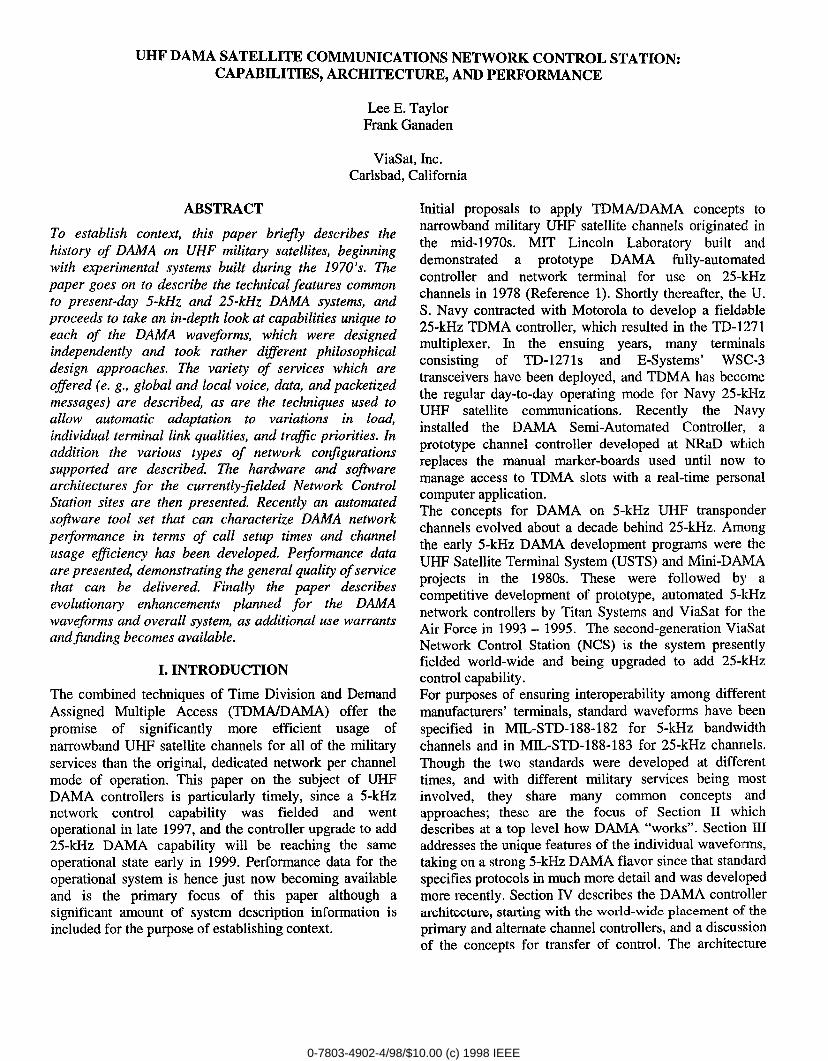
master time base to which all users on the channelsynchronize, and time slots that contain bursttransmissions originating from those individual channelcontroller and network terminals using the channel. Theslots must include “guard time” before and after eachterminal’s bursts, to accommodate timing drift betweeninstances when the terminal re-synchronizes. The use ofperiodic slots for communicating inherently continuousdata streams requires that the data be buffered at theoriginating terminal, resulting in end-to-end transit delaysthat do not occur in continuous transmission systems.Each controlled DAMA channel has four fundamentaltypes of slots. The first type is “forward” orderwiresoriginated by the NCS and containing control informationsuch as slot assignments for the population of networkterminals. Slot type two is ranging slots that aretransmitted and received by individual terminals and areused to measure signal propagation time from the terminalto the satellite. The third type is “reverse” orderwiresoriginated by the network terminals and containing controlinformation such as service requests for the NCS. Finally,the fourth category of slots contains communicationsbursts among pairs of users or network members. Bothwaveforms offer users a basic type of service; asynchronous, half-duplex circuit with destination(s)restricted to the “local” satellite footprint. Simpledepictions of the frame formats for 5- and 25-kHz DAMAare included in Figure 1.
8.96 sec
~ ContentionFOW .
j Contention ~ Assigned ~RNG ; ROW : RNG + ROW ~
COM ● *O
4 & 4
0 Frame duration
Forward ~ Range ! Reverse ~ UserOrderwire : Burst ~ Orderwire !
● **Communications
A
o v 1.386 sec
CCOW [ C:M : RNG ; ;;: [RCCOW; C:M :C:M ● .*
Figure 1: UHF DAMAFrame Formats
0-7803-4902-4/98/$10.00 (c) 1998 IEEE

With multiple network terminals using the. channel, andsome reverse orderwire slots allocated to “random access”(use by more than one terminal) there is a possibility thattwo terminals will transmit in the same slot, The result iscontention (mutual interference) such that neitherterminal’s burst can be successfully received on thesatellite downlink. Both military standards includeprovisions for handling this situation, consisting of re-transmission protocols that will ensure that the contentionis ultimately resolved.Data conveyed in the various types of slots can beprotected against the effects of transmission errors by theapplication of forward error correction codes. In addition,cyclic redundancy check coding on selected slots providesdetection of the rare errors that cannot be corrected.Various symbol burst rates can be selected; higher ratesbeing most efficient and lowest rates providing additionalrobustness for terminals with small antennas. In general,the orderwires are operated at the lowest burst rates andwith strongest coding, in order to guarantee the bestpossible reception by the most disadvantaged terminals.Finally, in the context of signal processing, the waveformsboth use phase modulation, whose constant-envelopeproperties are suited to the non-linear satellitetransponders. Orderwire data flowing in both directions aretypically encrypted to prevent traffic analysis.Just as in the public telephone system, a DAMA userneeds a destination number in order to place a call. TheDAMA address space has 216elements, which can signifyterminal port addresses, network addresses, or “guard”addresses (which can indicate an individual person,function, or mission). Calls may be placed point-to-point,multi-party conference calls may be established withoutpreplanning, or preplanned multi-party networks may beactivated, Requests for service include a numericprecedence level in the range 1 -5, so that when theoverall load exceeds channel capacity, lower precedencetraffic may be preempted. Each individual DAMA channelhas its own forward and reverse orderwire slots, so a giventerminal will typically remain on the channel it started outon – its “home” channel. In the event of high load on onechannel, however, the NCS can send one or moreterminals to a different DAMA channel; they can even becommanded to move from a 25-kHz to a 5-kHz channel(or vice versa). Finally, if very high priority users require achannel without TDMA buffering delays, the NCS canassign them temporarily to “dedicated” channels thatoperate full-duty-cycle in accordance with MIL-STD-188-181.In addition to a centralized time base generator, UHFDAMA employs a centralized channel controller, which“assigns” individual users and networks to time slots, Eachchannel controller has one or more alternates, typicallylocated at a different geographical site. Control may
transfer from primary to alternate under a number ofsituations, including an unplanned equipment outage at theprimary site, a primary site operator request to hand overcontrol to the alternate, or an alternate site operator requestto take control,
Parameter 5-kHz 25-kHz(MIL-STD-182) (MIL-STD-183)
Frame Duration 8.96 sec 1.3867 secBasic Time Unit 8.75 rnillisec 52 microsec
“building block” “chip”I/O Rates 75-2400 bps 75-16000 bpsBurst Rates 600-3000 SDS 9.6-16 kst)s +Guard Band Size 25.208 millisec 1.25 rnillisecModulation SOQPSK BPSKFEC Code Rates % ‘/2,%
Figure 2: Comparative UHF DAMA Numerics
111.UNIQUE FEATURES OF EACH WAVEFORM
Philosophically, the 5-kHz DAMA standard exerts muchtighter control over the population of network terminalsand is intended to be much more dynamic in adapting tochanging conditions. Terminals are required to log in withthe channel controller immediately upon acquiring thedownlink and uplink timing whereas in 25-kHz DAMA aterminal may passively monitor the channel and make itspresence known to the channel controller much later, usinga variety of reverse orderwire types. Typically this willoccur upon a status change such as putting an I/O port inservice or changing the port configuration of basebandequipment. Also there is a 5-kHz DAMA protocol to--ensure that the controller’s version of each- terminal’sguard list (all of the addresses associated with each I/Oport) remains consistent with the terminal’s version. Whendiscrepancies are detected the protocol automaticallybrings the lists back into a consistent state, accepting eitherthe channel controller or terminal version, under NCSoperator control for each terminal. The 5-kHz channelcontroller reconstructs the frame format and rebroadcastsslot assignments every frame ! This allows more or less ofthe frame, as demand requires, to be allocated to forwardand reverse orderwire traffic. It also allows immediatepreemption of lower precedence user traffic toaccommodate more important calls and for immediaterestoration of the preempted service once the higherprecedence call terminates. Basically, if a 5-kHz terminaldoes not receive its slot assignment in a frame, it ceasestransmitting; when the slot assignments start appearingagain, the terminal resumes usage of the slots. Finally, thecontinuous broadcast of service assignments allowsterminals that log in late to immediately join establishednetworks. In contrast, the 25-kHz waveform sends a slot
0-7803-4902-4/98/$10.00 (c) 1998 IEEE

connect in a single frame and then does not repeat it. Thusthe channel controller must originate a new copy of theslot assignment in order to bring a late entering terminalinto a network; and the controller must send a slotdisconnect orderwire message in order to force a call offthe air. As a result of its more fixed frame format, the 25-kHz waveform offers precisely one forward orderwiremessage and one reverse orderwire message slot perframe. Similarly segments of the 25-kHz frame devoted touser communications take on a relatively fixed format;they can change but generally not from one frame to thenext. So, if the current 25-kHz DAMA frame format isstructured for, say, nine 1200 bps slots and one 75 bps slot(the format designated “9, B, A“) and some of these slotsare assigned to active calls, the channel controller mayrequire several frames to change the format in order toaccommodate a 2400 bps call. The 5-kHz waveform issufficiently dynamic that the controller can immediatelycompress the existing services into the end of the frameand create a 2400 bps slot.The 25-kHz DAMA waveform provides an end-end linkquality measurement capability, At the request of eitherthe channel controller operator or a terminal operator, theterminal can be assigned the single link test slot (seeFigure 1) for enough frames to accumulate statisticallysignificant bit error rate data. The terminal itself originatesthe uplink and receives the downlink, so this constitutes atrue end-to-end link test. The burst rate is variable over theoptions available for communications services, so the datamay be related directly to performance in thecommunications slots. Once the link test is completed, biterror rate results are displayed at the terminal and reportedto the channel controller using a reverse orderwiremessage. At present the channel controller does notautomatically use the link test data in selecting acommunications slot with appropriate burst and code rates,since bit error rates rather than carrier to noise densityratios are reported. The capability to report C/No is afeature of the next-generation 25-kHz standard (“183A”)and will ultimately be used by the 25-kHz controller. Incontrast, 5-kHz DAMA network terminals derive linkquality information by processing forward orderwire burstsover many frames. This technique has the limitations ofproviding information only on the terminal’s downlink andonly at the very robust 800 sps rate 1/2 coded mode.Nevertheless, results are periodically sent to the channelcontroller in reverse orderwire status reports, and thecontroller uses the results to automatically select burst andcode rates which will ensure adequate performance for theweakest terminal in the service. The 5-kHz controllerstrives to achieve 10-3 bit error rate (BER) for voiceservices and 10-5BER for data services.In addition to the generic half-duplex, synchronous, local-footprint circuit service type offered by both waveforms,
5-kHz DAMA distinguishes between voice circuits anddata circuits for BER purposes. Also, MIL-STD-182includes the structure for handling start, stop, and fill bitsnecessary for operation of asynchronous data I/O. Beyondcircuit services, the 5-kHz waveform includes packetized,simplex “message” services. When the length of a datacommunication is precisely known a priori, such as in thecase of a computer-to-computer file transfer, the messagecan be divided into small packets and sent at a variable I/Orate per frame, in the background relative to the circuitservices. Exactly enough packets are allocated to just fillup each frame, after all active circuit services have beenaccommodated. This feature allows highly efficient usageof the available channel capacity. At present messagelength is limited to 114688 bits because of possiblecumulative timing drift between source and destination.Point-to-point message services includeacknowledgements of each burst and of the entiremessage, providing an extremely reliable form ofcommunication. Another service-oriented capabilityunique to 5-kHz DAMA is global connectivity, whichapplies to all point-to-point (vs. network) calls. The world-wide complement of channel controllers intercommunicateand have the intelligence to find a user anywhere globallyand to automatically relay traffic through multiple satellitehops until it reaches the proper destination.5-kHz DAMA terminrds are required to specify in eachservice request whether the traffic is voice or data andwhether the I/O is synchronous or asynchronous. A quitedifferent approach is used with 25-kHz DAMA, where theterminal originating the service specifies one of 99“configuration codes”, the specific values of which are leftopen to be operationally assigned. Each code willcorrespond to a complete string of I/O equipment, so inaddition to voice/data and sync/asynchronous it conveyswhether the port is attached to an encryption unit, if sowhat model, and what variety of I/O device is currentlyattached.A unique feature of the 25-kHz DAMA waveform is theability to assign slots in a second channel. This is termed a“frequency-switched slot connect”, and requires theparticipating terminals to tune their radios twice per frame,such that they access orderwires on the home channel andhandle communications bursts on the other channel. Asecond unique 25-kHz DAMA capability is a call waitingalert similar to that offered in commercial telephony. If auser is denied connection to a second party because thesecond party is busy with higher precedence traffic, theoriginating user may manually send a “paging” reverseorderwire and the channel controller will originate a “callwaiting” forward orderwire which may be displayed at thebusy party’s terminal.One noteworthy unique feature of 5-kHz DAMA is theability for users to notify the channel controller that their
0-7803-4902-4/98/$10.00 (c) 1998 IEEE
use of a slot is completed, using an in-band signal ratherthan taking the time and bandwidth to send a reverseorderwire. The terminal simply inserts a special 12-bit“tear-down” code in the circuit burst kind (CBK) field ofthe last transmitted burst. Since the channel controllermonitors usage of every slot, upon receipt of the teardownCBK, the controller broadcasts a teardown forwardorderwire and immediately puts the slot back into theavailable pool. Another unique 5-kHz concept is the“future forward orderwire”. The first few fields of a FutureFOW are well defined so that the message can berecognized by old terminals and ignored, whereasterminals fielded since the remainder of the Future FOWfields were defined can go on to process the rest of themessage and hence offer advanced capabilities. Thisfeature greatly facilitates interoperability among old andnew terminals; the channel controller must, of course, keeprecords of which terminals support which versions of themilitary standard.
IV. DAMA ARCHITECTURE
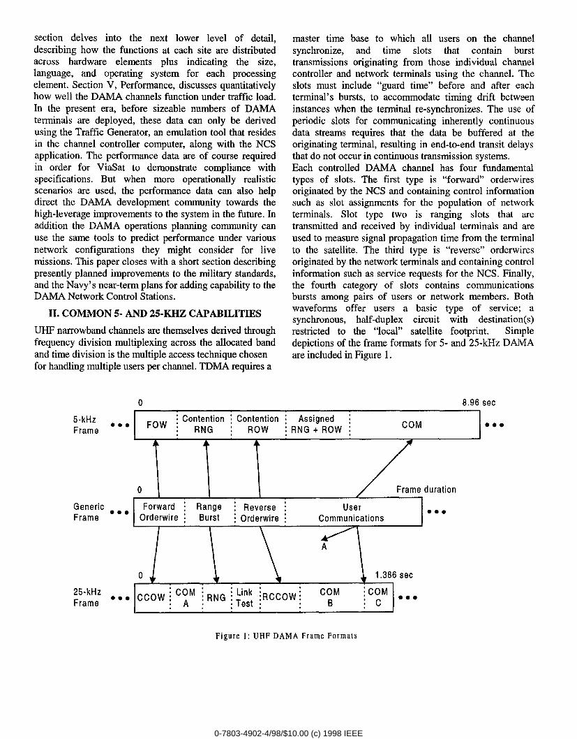
The DAMA “system” is comprised of the entire suite ofNCS equipment at all four sites worldwide: Norfolk,Naples, Guam, and Hawaii. Each site is termed an NCS“segment” and has both an east side and a west side forcontrolling channels on satellites in the two directions. For5-kHz global traffic relaying purposes, the east and westsides are connected by a local area network. The system-level architecture is depicted in Fig. 3, which indicatesCONUS, Atlantic, Pacific, and Indian Ocean satellites plustwo Network Terminals.
CONUS PAC
LANT 10
Figure 3: UHF DAMA World-wide Architecture
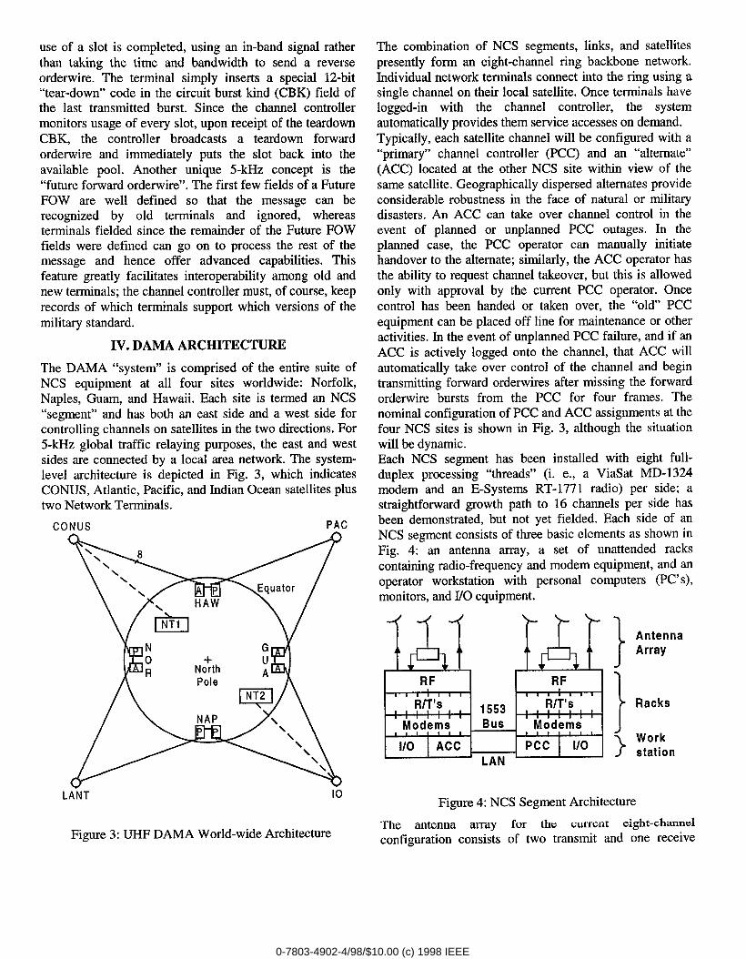
The combination of NCS segments, links, and satellitespresently form an eight-channel ring backbone network.Individual network terminals connect into the ring using asingle channel on their local satellite. Once terminals havelogged-in with the channel controller, the systemautomatically provides them service accesses on demand.Typically, each satellite channel will be configured with a“primary” channel controller (PCC) and an “alternate”(ACC) located at the other NCS site within view of thesame satellite. Geographically dispersed alternates provideconsiderable robustness in the face of natural or militarydisasters. An ACC can take over channel control in theevent of planned or unplanned PCC outages. In theplanned case, the PCC operator can manually initiatehandover to the alternate; similarly, the ACC operator hasthe ability to request channel takeover, but this is allowedonly with approval by the current PCC operator. Oncecontrol has been handed or taken over, the “old” PCCequipment can be placed off line for maintenance or otheractivities. In the event of unplanned PCC failure, and if anACC is actively logged onto the channel, that ACC willautomatically take over control of the channel and begintransmitting forward orderwires after missing the forwardorderwire bursts from the PCC for four frames. Thenominal configuration of PCC and ACC assignments at thefour NCS sites is shown in Fig. 3, although the situationwill be dynamic.Each NCS segment has been installed with eight full-duplex processing “threads” (i. e., a ViaSat MD-1324modem and an E-Systems RT- 1771 radio) per side; astraightforward growth path to 16 channels per side hasbeen demonstrated, but not yet fielded. Each side of anNCS segment consists of three basic elements as shown inFig. 4: an antenna array, a set of unattended rackscontaining radio-frequency and modem equipment, and anoperator workstation with personal computers (PC’s),monitors, and I/O equipment.
4 )-
Ak Ab AL Ah
RF RF, , 1 1 1 1 I 1 I , 1 I 1 I
R/T’s1 1 1553 R/T’sI #1 1 , I 1 , I 1 I 1 tModems BUS Modems1 t1/0 ACC Pcc 1/0
LAN
}
AntennaArray
}
Racks
}Workstation
Figure 4: NCS Segment Architecture
The antenna array for the current eight-channelconfiguration consists of two transmit and one receive
0-7803-4902-4/98/$10.00 (c) 1998 IEEE
antennas per side. A photograph of the Hawaii antennaarray is included as Figure 5. The photograph shows allthree west side antennas, the east side receive antenna, andone of the east side transmit antennas which is shown inthe foreground. In situations with multiple closely spacedsatellites, the NCS antennas are typically pointed to accessall spacecraft, rather than being optimized for a particularsatellite.
Figure 6: NCS Equipment Racks
Figure 5: NCS Antenna Array
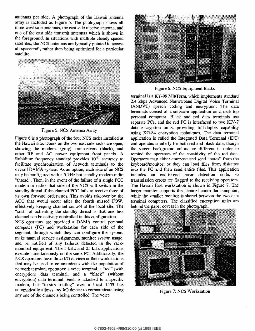
Figure 6 is a photograph of the four NCS racks installed atthe Hawaii site. Doors on the two east side racks are open,showing the modems (gray), transceivers (black), andother RF and AC power equipment front panels. ARubidium frequency standard provides 10-11accuracy tofacilitate synchronization of network terminals to theoverall DAMA system. As an option, each side of arINCSmay be configured with a 5-kHz hot standby modem-radio“thread”. Then, in the event of the failure of a single PCCmodem or radio, that side of the NCS will switch in thestandby thread if the channel PCC fails to receive three ofits own forward orderwires. This avoids takeover by theACC that would occur after the fourth missed FOW,effectively keeping channel control at the local site. The“cost” of activating the standby thread is that one lesschannel can be actively controlled in this configuration.NCS operators are provided a DAMA control personalcomputer (PC) and workstation for each side of thesegment, through which they can configure the system,make manual service assignments, monitor system usage,and be notified of any failures detected in the rack-mounted equipment. The 5-kHz and 25-kHz applicationsexecute simultaneously on the same PC. Additionally, theNCS operators have three I/O devices at their workstationsthat may be used to communicate with the population ofnetwork terminal operators: a voice terminal, a “red” (withencryption) data terminal, and a “black” (withoutencryption) data terminal. Each is attached to a specificmodem, but “in-site routing” over a local 1553 busautomatically allows any I/O device to communicate usingany one of the channels being controlled. The voice
terminal is a KY-99 MinTerm, which implements standard2.4 kbps Advanced Narrowband Digital Voice Terminal(ANDVT) speech coding and encryption. The dataterminals consist of a software application on a desk-toppersonal computer. Black and red data terminals useseparate PCs, and the red PC is interfaced to two KIV-7data encryption units, providing full-duplex capabilityusing KG-84 encryption techniques. The data terminalapplication is called the Integrated Data Terminal (IDT)and operates similarly for both red and black data, thoughthe screen background colors are different in order toremind the operators of the sensitivity of the red data.Operators may either compose and send “notes” from thekeyboard/monitor, or they can load files from diskettesinto the PC and then send entire files. This applicationincludes an end-to-end error detection code, sotransmission errors are flagged to the receiving operators.The Hawaii East workstation is shown in Figure 7. Thelarger monitor supports the channel controller computer,while the smaller monitor is shared between the two dataterminal computers. The classified encryption units arebehind the paper covers in the photograph.
Figure 7: NCS Workstation
0-7803-4902-4/98/$10.00 (c) 1998 IEEE
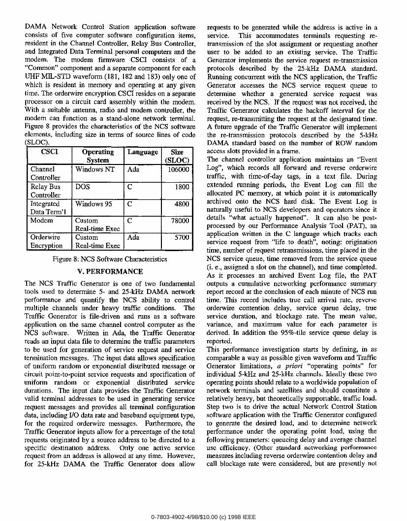
DAMA Network Control Station application softwareconsists of five computer software configuration items,resident in the Channel Controller, Relay Bus Controller,and Integrated Data Terminal personal computers and themodem. The modem firmware CSCI consists of a“Common” component and a separate component for eachUHF MIL-STD waveform (181, 182 and 183) only one ofwhich is resident in memory and operating at any giventime. The orderwire encryption CSCI resides on a separateprocessor on a circuit card assembly within the modem.With a suitable antenna, radio and modem controller, themodem can function as a stand-alone network terminal.Figure 8 provides the characteristics of the NCS softwareelements, including size in terms of source lines of code
;LOC). -CSCI Operating Language Size
System (SLOC)Channel Windows NT Ada 106000ControllerRelay Bus DOS c 1800ControllerIntegrated Windows 95 c 4800Data Term’1Modem Custom c 78000
Real-time ExecOrderwire Custom Ada 5700Encryption Real-time Exec
Figure 8: NCS Software Characteristics
V. PERFORMANCE
The NCS Traffic Generator is one of two fundamentaltools used to determine 5- and 25-kHz DAMA networkperformance and quantify the NCS ability to controlmultiple channels under heavy traffic conditions. TheTraffic Generator is file-driven and runs as a softwareapplication on the same channel control computer as theNCS software. Written in Ada, the Traffic Generatorreads an input data file to determine the traffic parametersto be used for generation of service request and servicetermination messages. The input data allows specificationof uniform random or exponential distributed message orcircuit point-to-point service requests and specification ofuniform random or exponential distributed servicedurations. The input data provides the Traffic Generatorvalid terminal addresses to be used in generating servicerequest messages and provides all terminal configurationdata, including I/O data rate and baseband equipment type,for the required orderwire messages, Furthermore, theTraffic Generator inputs allow for a percentage of the totalrequests originated by a source address to be directed to aspecific destination address. Only one active servicerequest from an address is allowed at any time. However,for 25-kHz DAMA the Traffic Generator does allow
requests to be generated while the address is active in aservice. This accommodates terminals requesting re-transmission of the slot assignment or requesting anotheruser to be added to an existing service. The TrafficGenerator implements the service request re-transrnissionprotocols described by the 25-kHz DAMA standard.Running concurrent with the NCS application, the TrafficGenerator accesses the NCS service request queue todetermine whether a generated service request wasreceived by the NCS. If the request was not received, theTraffic Generator calculates the backoff interval for therequest, re-transmitting the request at the designated time.A future upgrade of the Traffic Generator will implementthe re-transrnission protocols described by the 5-kHzDAMA standard based on the number of ROW randomaccess slots provided in a frame.The channel controller application maintains an “EventLog”, which records all forward and reverse orderwiretraffic, with time-of-day tags, in a text file, Duringextended running periods, the Event Log can fill theallocated PC memory, at which point it is automaticallyarchived onto the NCS hard disk. The Event Log isnaturally useful to NCS developers and operators since itdetails “what actually happened”. It can also be post-processed by our Performance Analysis Tool (PAT), anapplication written in the C language which tracks eachservice request from “life to death”, noting: originationtime, number of request retransmissions, time placed in theNCS service queue, time removed from the service queue(i. e., assigned a slot on the channel), and time completed.As it processes an archived Event Log file, the PAToutputs a cumulative networking performance summaryreport record at the conclusion of each minute of NCS runtime. This record includes true call arrival rate, reverseorderwire contention delay, service queue delay, trueservice duration, and blockage rate. The mean value,variance, and maximum value for each parameter isderived. In addition the 95%-tile service queue delay isreported.This performance investigation starts by defining, in ascomparable a way as possible given waveform and TrafficGenerator limitations, a priori “operating points” forindividual 5-kHz and 25-kHz channels. Ideally these twooperating points should relate to a worldwide population ofnetwork terminals and satellites and should constitute arelatively heavy, but theoretically supportable, traffic load.Step two is to drive the actual Network Control Stationsoftware application with the Traffic Generator configuredto generate the desired load, and to determine networkperformance under the operating point load, using thefollowing parameters: queueing delay and average channeluse efficiency, (Other standard networking performancemeasures including reverse orderwire contention delay andcall blockage rate were considered, but are presently not
0-7803-4902-4/98/$10.00 (c) 1998 IEEE
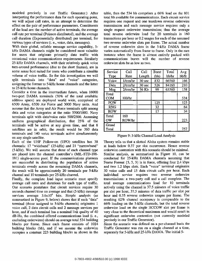
modeled precisely in our Traffic Generator.) Afterinterpreting the performance data for each operating point,we will adjust call rates, in an attempt to determine theeffect on the pair of performance parameters. Constituentsof the load are: the number of active terminals, the averagecall rate per terminal (Poisson distributed), and the averagecall duration (Exponentially distributed) per terminal, forvarious types of services (i. e., voice, data, messages).With their global, reliable message service capability, 5-kHz DAMA channels might be considered most valuablefor users that originate primarily data traffic withoccasional voice communications requirements. Similarly25-kHz DAMA channels, with their relatively quick voiceturn-around performance (due to the short frames), are insome sense best suited for users who contribute a sizeablevolume of voice traffic. So for this investigation we willsplit terminals into “data” and “voice” categories,assigning the former to 5-kHz home channels and the latterto 25-kHz home channels.Consider a time in the intermediate future, when 16000two-port DAMA terminals (5090 of the total availableaddress space) are deployed world wide, comprised of6500 Army, 6500 Air Force and 3000 Navy units. Andassume that the Army and Air Force terminals split amongdata and voice categories at the ratio 5500/1000. Navyterminals split with datahoice ratio 500/2500. Assuminguniform geographical distribution, that 25% of theterminals will be active at any given time, and that 8satellites are in orbit, the result would be 360 dataterminals and 140 voice terminals active simultaneouslyon any single satellite.Each of the UHF Follow-on (UFO) satellites has 38channels: 17 “wideband” (25-kHz) and 21 “narrowband”(5-kHz). We will assume that three of each channel typeare placed into the channel controller’s (MIL-STD-188-181) single-access pool. If the communications plannersare successful in distributing the population of activeterminals evenly across the remaining DAMA channels,the result will be approximately 20 terminals per 5-kHzchannel and 10 terminals per 25-kHz channel.Finally, the complete load input scenario must specifyaverage call rates and durations for each type of traffic.Our scenario postulates that circuit services require 30seconds channel time on average and that (5-kHz) messageservices average 3.6x104 bits. Simple analysis (assummarized in Figure 9, below) shows that if each “data”terminal (those assigned to 5-kHz channels) originates 1voice call, 2 data circuit calls and 2 message services perhour, and if each terminal has a nominal link quality of 40dB-Hz, the combined offered communications load (i. e.,excluding orderwires) should on average total 534 buildingblocks per frame. Since each frame consists of 1024building blocks (bb), and if we assume the orderwireoccupies a constant 223 building blocks as shown in the
table, then the 534 bb comprises a 66V0load on the 801total bb available for communications. Each circuit servicerequires one request and one teardown reverse orderwiretransmission and each message service requires only asingle request orderwire transmission; thus the averagetotal reverse orderwire load for 20 terminals is 160transactions per hour or 0.2 usages for each of the assumedtwo reverse orderwire slots per frame. The actual numberof reverse orderwire slots in the 5-kHz DAMA framevaries automatically from frame to frame. Only in the rareinstance when the frame is almost entirely packed withcommunications bursts will the number of reverseorderwire slots be as low as two.
Service Call Call Burst Total AvgType Rate Length (bb) bblhr bbffrVoice I/trm/hr 30 sec 832 66560 166Data 2/trm/hr 30 sec 526 84160 210Msg 2/trm/hr 36 Kb 99 63360 158
TotalCOM 100/hr 534
FOW 125 125RNG 32 64ROW 17 34
Total 160Ow ROW/hr 223GrandTotal 757
Figure 9: 5-kHz Channel Load Analysis
Theory tells us that a slotted Aloha system remains stableat loads below 0.37 per slot occurrence. Hence reverseorderwire contention with this scenario should be minimal.Similar analysis, as summarized in Figure 10, can beconducted for 25-kHz DAMA channels assuming thatFrame Format {5, 5, 3} is in force, offering four 2.4 kbpsand two 1.2 kbps slots. Each “voice” terminal originates30 voice calls and 15 data circuit calls per hour. Eachindividual service requires two reverse orderwiretransmissions: a two-party call and a call complete. Thetotal average communications load for 10 terminalsactively using the channel is 37.5 minutes of voice trafficper slot per hour, 37.5 minutes of data traffic per slot perhour and 0.35 reverse orderwire usages per frame. Theresulting 62% channel occupancy is comparable to the66% loading on the 5-kHz channels, but the total reverseorderwire load on the single RCCOW slot per frame isvery close to the theoretical maximum and would result insignificant orderwire contention (not currently modeledprecisely in our Traffic Generator).Since the scenario was defined on a per-channel basis theTraffic Generator was run on a single channel at a time,separately for 5-kHz and 25-kHz DAMA. The initial 5-
0-7803-4902-4/98/$10.00 (c) 1998 IEEE

I Service Call I Call I Total IType Rate Length /slot/hrVoice 30/term/hr 30 sec 37.5 minutesData 15/terrn/hr 30 sec 37.5 minutes
TotalCOM 450 calls/hrTotal 900Ow RCCOW/hr
Figure 10: 25-kHz Channel Load Analysis
kHz performance measurement was taken over a period of13 hours and resulted in 1292 service requests. This total isslightly low compared to the expected value of 1312requests for that period, and differs as a result of a finitepopulation effect; the Traffic Generator creates no newservice requests from a given 110 port while that port isstill busy with earlier traffic. Circuit service durationaveraged 38 seconds overall. This is higher than the 30second specified value because of two phenomena. First,each service must fill an integer number of frames, so theresultant rounding up adds a half frame (4.5 seconds) tothe average. Second, contention in reverse orderwire slotsdelays some of the teardown messages; the associatedservice is extended until the teardown is finally receivedby the channel controller. Average queueing delay for our
●
o-0 20 40 60 80 100 120 1
Average Load (calls per hour)
Figure 11: 5-kHz NCS DAMA Queueing Performance
initial operating point was 37 seconds as depicted inFigure 11, Since all calls were of the same precedencethere could be no preemption, so some calls had to waituntil preyioufi uwm finifih~d on th~ Qhannvl b~fvr~ theycould be assigned channel time. Complexities with thecomposite message and circuit traffic plus the dynamic 5-
kHz frame format have thus far precluded deriving apurely analytical result against which to compare the 37second experimental queueing delay value. We haveanalytical results for the less complex 25-kHz case,however (see below). Recall that the 5-kHz operating pointwas designed to generate approximately 6670 averagechannel usage. For one frame during each minute of thescenario, the Performance Analysis Tool tallies the numberof building blocks assigned to communications servicesand the actual number of building blocks available forassignments after accommodating the FOW and contentionranging slots. Percent channel usage was derived byaveraging this ratio over a period of 100 minutesbeginning three minutes into the scenario. This issufficient time for the channel loading to reach a steadystate. Data for this run converged well to a 70V0 usagevalue with 100 samples. The extended service durationsdue to frame-filling and orderwire contention mentionedabove are believed to be the primary reason why measuredusage exceeded the predicted value.To assess the affect of load variation on our twoperformance measures, we conducted additional 5-kHzruns at 25, 50, 75 and 12590 of the operating point load.Running at 125% was feasible since loading on the reverseorderwire at the 1009o operating point was well under theslotted Aloha theoretical maximum. The results for both
0,8
0.7
006a01a2zzwCmw
z
0.2
0.1
.u.
o 20 40 60 80 100 120 1Average Load (calls per hour)
o
Figure 12: 5-kHz NCS DAMA Slot Usage Efficiency
the initial operating point and the load excursions areplotted in Figures 11 and 12. Queueing delays shouldtheoretically tend towards zero as load diminishes. Ourexpaimrzmd data rdlums th~ implemvntr+tkm, howev=,tending towards a half frame (4.5 seconds) becauserequests are presented to the channel controller at times
0-7803-4902-4/98/$10.00 (c) 1998 IEEE
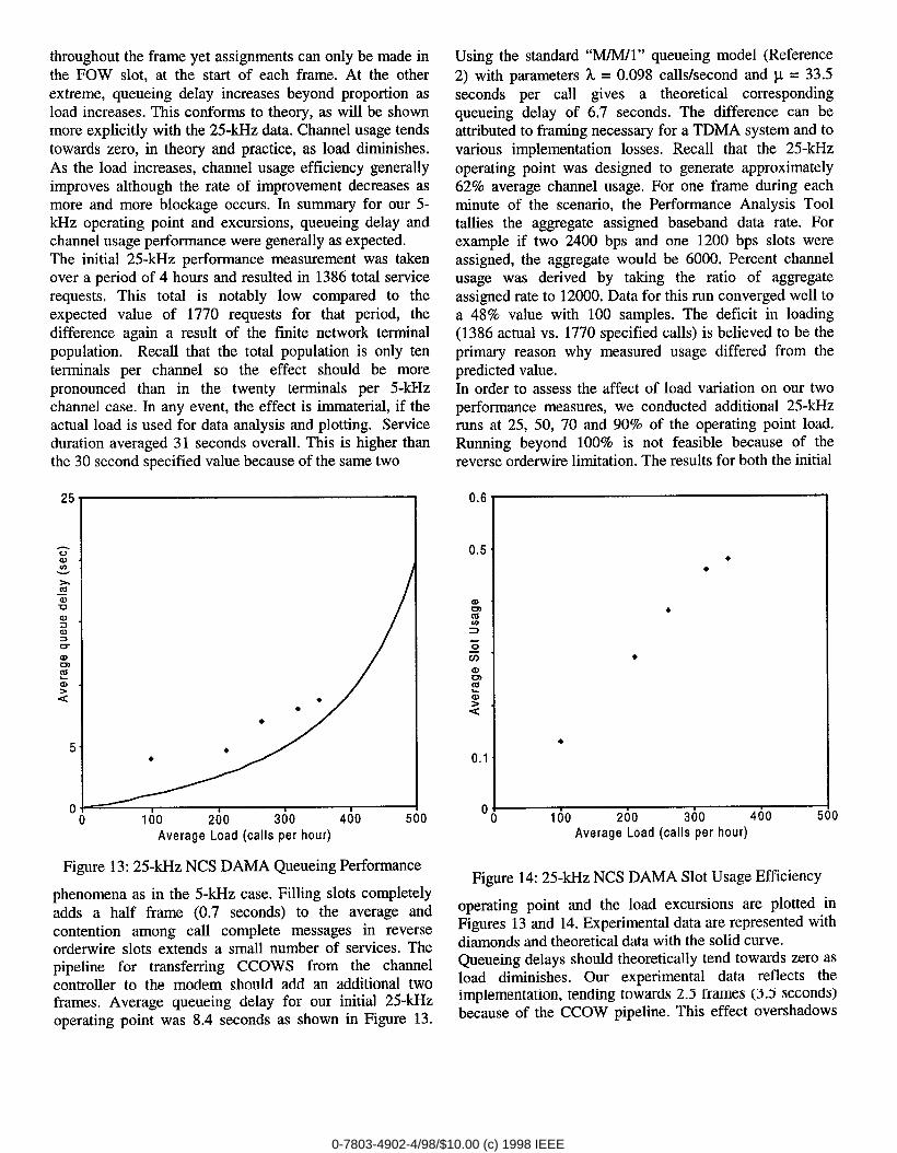
throughout the frame yet assignments can only be made inthe FOW slot, at the start of each frame. At the otherextreme, queueing delay increases beyond proportion asload increases. This conforms to theory, as will be shownmore explicitly with the 25-kHz data. Channel usage tendstowards zero, in theory and practice, as load diminishes.As the load increases, channel usage efficiency generallyimproves although the rate of improvement decreases asmore and more blockage occurs. In summary for our 5-kHz operating point and excursions, queueing delay andchannel usage performance were generally as expected.The initial 25-kHz performance measurement was takenover a period of 4 hours and resulted in 1386 total servicerequests, This total is notably low compared to theexpected value of 1770 requests for that period, thedifference again a result of the finite network terminalpopulation. Recall that the total population is only tenterminals per channel so the effect should be morepronounced than in the twenty terminals per 5-kHzchannel case. In any event, the effect is immaterial, if theactual load is used for data analysis and plotting. Serviceduration averaged 31 seconds overall. This is higher thanthe 30 second ~pecified value because of the same-two
●
0 , I
0 100 200 300 400 5(Average Load (calls per hour)
Figure 13: 25-kHz NCS DAMA Queueing Performance
phenomena as in the 5-kHz case. Filling slots completelyadds a half frame (0.7 seconds) to the average andcontention among call complete messages in reverseorderwire slots extends a small number of services. Thepipeline for transferring CCOWS from the channelcontroller to the modem should add an additional twoframes. Average queueing delay for our initial 25-kHzoperating point was 8.4 seconds as shown in Figure 13.
Using the standard “M/M/l” queueing model (Reference2) with parameters 1. = 0.098 calls/second and p = 33.5seconds per call gives a theoretical correspondingqueueing delay of 6.7 seconds. The difference can beattributed to framing necessary for a TDMA system and tovarious implementation losses. Recall that the 25-kHzoperating point was designed to generate approximately62% average channel usage. For one frame during eachminute of the scenario, the Performance Analysis Tooltallies the aggregate assigned baseband data rate. Forexample if two 2400 bps and one 1200 bps slots wereassigned, the aggregate would be 6000. Percent channelusage was derived by taking the ratio of aggregateassigned rate to 12000. Data for this run converged well toa 48% value with 100 samples. The deficit in loading(1386 actual vs. 1770 specified calls) is believed to be theprimary reason why measured usage differed from thepredicted value.In order to assess the affect of load variation on our twoperformance measures, we conducted additional 25-kHzruns at 25, 50, 70 and 90% of the operating point load.Running beyond 100% is not feasible because of thereverse orderwire limitation. The results for both the initial
●
4
100 200 300 400 5( )Average Load (calls per hour)
Figure 14: 25-kHz NCS DAMA Slot Usage Efficiency
operating point and the load excursions are plotted inFigures 13 and 14. Experimental data are represented withdiamonds and theoretical data with the solid curve.Queueing delays should theoretically tend towards zero asload diminishes. Our experimental data reflects theimplementation, tending towards 2.5 frames (3.5 seconds)because of the CCOW pipeline. This effect overshadows
0-7803-4902-4/98/$10.00 (c) 1998 IEEE
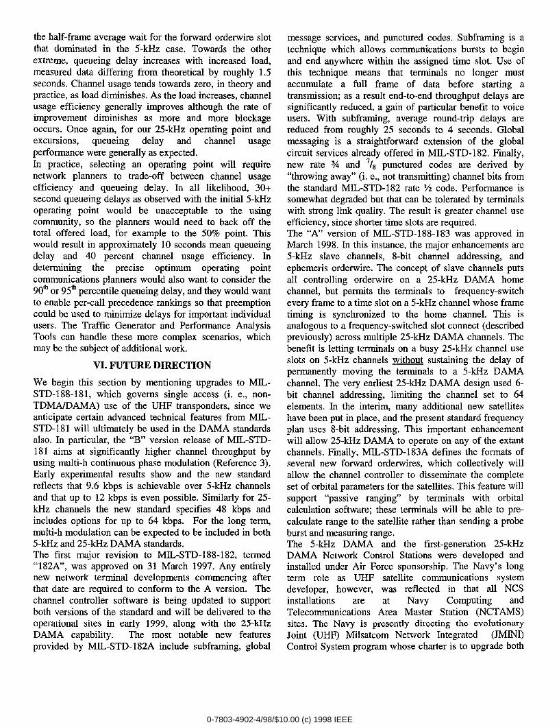
the half-frame average wait for the forward orderwire slotthat dominated in the 5-kHz case. Towards the otherextreme, queueing delay increases with increased load,measured data differing from theoretical by roughly 1.5seconds. Channel usage tends towards zero, in theory andpractice, as load diminishes. As the load increases, channelusage efficiency generally improves although the rate ofimprovement diminishes as more and more blockageoccurs. Once again, for our 25-kHz operating point andexcursions, queueing delay and channel usageperformance were generally as expected.In practice, selecting an operating point will requirenetwork planners to trade-off between channel usageefficiency and queueing delay. In all likelihood, 30+second queueing delays as observed with the initial 5-kHzoperating point would be unacceptable to the usingcommunity, so the planners would need to back off thetotal offered load, for example to the 50% point. Thiswould result in approximately 10 seconds mean queueingdelay and 40 percent channel usage efficiency. Indetermining the precise optimum operating pointcommunications planners would also want to consider the90* or 95* percentile queueing delay, and they would wantto enable per-call precedence rankings so that preemptioncould be used to minimize delays for important individualusers. The Traffic Generator and Performance AnalysisTools can handle these more complex scenarios, whichmay be the subject of additional work.
VI. FUTURE DIRECTION
We begin this section by mentioning upgrades to MIL-STD-188-18 1, which governs single access (i. e., non-TDMA/DAMA) use of the UHF transponders, since weanticipate certain advanced technical features from MIL-STD-181 will ultimately be used in the DAMA standardsalso. In particular, the “B” version release of MIL-STD-181 aims at significantly higher channel throughput byusing multi-h continuous phase modulation (Reference 3).Early experimental results show and the new standardreflects that 9.6 kbps is achievable over 5-kHz channelsand that up to 12 kbps is even possible. Similarly for 25-kHz channels the new standard specifies 48 kbps andincludes options for up to 64 kbps. For the long term,multi-h modulation can be expected to be included in both5-kHz and 25-kHz DAMA standards.The first major revision to MIL-STD-188-182, termed“182A”, was approved on 31 March 1997. Any entirelynew network terminal developments commencing afterthat date are required to conform to the A version. Thechannel controller software is being updated to supportboth versions of the standard and will be delivered to theoperational sites in early 1999, along with the 25-kHzDAMA capability. The most notable new featuresprovided by MIL-STD-182A include subframing, global
message services, and punctured codes. Subframing is atechnique which allows communications bursts to beginand end anywhere within the assigned time slot. Use ofthis technique means that terminals no longer mustaccumulate a full frame of data before starting atransmission; as a result end-to-end throughput delays aresignificantly reduced, a gain of particular benefit to voiceusers. With subframing, average round-trip delays arereduced from roughly 25 seconds to 4 seconds. Globalmessaging is a straightforward extension of the globalcircuit services already offered in MIL-STD- 182. Finally,new rate Y4 and 7/s punctured codes are derived by“throwing away” (i. e., not transmitting) channel bits fromthe standard MIL-STD-182 rate % code. Performance issomewhat degraded but that can be tolerated by terminalswith strong link quality. The result is greater channel useefficiency, since shorter time slots are required.The “A” version of MIL-STD-188-183 was approved inMarch 1998. In this instance, the major enhancements are5-kHz slave channels, 8-bit channel addressing, andephemeris orderwire. The concept of slave channels putsall controlling orderwire on a 25-kHz DAMA homechannel, but permits the terminals to frequency-switchevery frame to a time slot on a 5-kHz channel whose frametiming is synchronized to the home channel. This isanalogous to a frequency-switched slot connect (describedpreviously) across multiple 254cHz DAMA channels. Thebenefit is letting terminals on a busy 25-kHz channel useslots on 5-kHz channels without sustaining the delay ofpermanently moving the terminals to a 5-kHz DAMAchannel, The very earliest 25-kHz DAMA design used 6-bit channel addressing, limiting the channel set to 64elements. In the interim, many additional new satelliteshave been put in place, and the present standard frequencyplan uses 8-bit addressing. This important enhancementwill allow 25-kHz DAMA to operate on any of the extantchannels. Finally, MIL-STD- 183A defines the formats ofseveral new forward orderwires, which collectively willallow the channel controller to disseminate the completeset of orbital parameters for the satellites. This feature willsupport “passive ranging” by terminals with orbitalcalculation software; these terminals will be able to pre-calculate range to the satellite rather than sending a probeburst and measuring range.The 5-kHz DAMA and the first-generation 25-kHzDAMA Network Control Stations were developed andinstalled under Air Force sponsorship, The Navy’s longterm role as UHF satellite communications systemdeveloper, however, was reflected in that all NCSinstallations are at Navy Computing andTelecommunications Area Master Station (NCTAMS)sites. The Navy is presently directing the evolutionaryJoint (UHF) Milsatcom Network Integrated (JMINI)Control System program whose charter is to upgrade both
0-7803-4902-4/98/$10.00 (c) 1998 IEEE
5-kHz and 25-kHz DAMA. Two significant early JMINIimprovements will be inclusion of a Network ManagementSystem (NMS), and achievement of channelsynchronization. The NMS will be a communicationsplanning tool, instances of which will reside at Joint Chiefsof Staff, various commanders in chief (CINCS) who “own”individual satellite channels, and the NCS sites, allinterconnected through a secure network. It will bethrough the NMS that all decisions concerningapportionment of the channels and ranking of individualterminal’s and network’s importance will be made anddisseminated. The ultimate destination of the “rules” forassignment of capacity will be downloaded into the NCScomputers and implemented in real-time as requests forservice arrive. Presently, frame timing for DAMAchannels is synchronized on a per site basis and at the timeof transmission from the ground. Maximally useful systemsynchronization requires alignment at the satellite, and forevery channel (both 5-kHz and 25-kHz) world-wide.Benefits are numerous and major, the prime ones beingallowing cross-channel scheduling and precluding frametiming jumps upon transfer of control to an alternatestation. This will be a big step towards “seamless” 5 and25-kHz DAMA wherein users will not need to concernthemselves with implementation details; they wouldsimply request services and be assigned an appropriateslot.After more than 20 years of evolution and development,network controllers for both 5-kHz and 25-kHz standardUHF DAMA waveforms have been recently fielded. Largenumbers of network terminals designed to the standardwaveforms are just now going operational, andcommanders are expected to convert more and morechannels to the DAMA mode as the user populationwarrants. This paper addressed performance of the overall
DAMA system. The approach was to use a discrete eventsimulator to impose traffic loads close to the theoreticalmaximum on the actual channel controller software, and tomeasure key networking performance parameters, It wasdemonstrated that the system provides good quality serviceunder heavy loads.
ACKNOWLEDGEMENTS
The authors are most indebted to Dr. John Bacigalupi, whoextended the Traffic Generator capability to include 25-kHz DAMA and who conducted all of the simulation runs.Development and fielding of the DAMA Network ControlStation were funded by the U. S. Air Force ElectronicsSystems Center, Maj. Brian Casey, Program Manager.Enhancements to channel controllers are presently beingconducted under the auspices of the U. S. Navy Space andElectronic Warfare (SPAWAR) center, Mr. James Parsons,Program Manager.
1.
2.
3,
3.
4.
5.
REFERENCES
L. E. Taylor and S. L. Bernstein, “TACS – A DemandAssignment System for FLEETSAT,” IEEE Transactions onCommunications, Vol. COM-’27,No. 10, October 1979.
D. Gross and C. M. Harris, “Fundamentals of QueueingTheory,” Wiley and Sons, 1974.
I. Sasase and S. Mori, “Multi-h Phase-Coded Modulation,”IEEE Communications Vol. 29, No. 12, December 1991.
MIL-STD-188-181, “Interoperability Standard forDedicated 5-kHz and 25 kHz UHF SatelliteCommunications Channels,” 18 September 1992.
MIL-STD-1 88-182, “Interoperability Standard for 5-kHzUHF DAMA Terminal Waveform,” 18 September 1992.
MIL-STD-188-183, “Interoperability Standard for 25-kHzUHF TDMA./DAMA Terminal Waveform,” 18 September1992.
0-7803-4902-4/98/$10.00 (c) 1998 IEEE