daikin engineering data split (cooling only) j-series (2015)
DESCRIPTION
Daikin Engineering Data Split (Cooling Only) J-Series (2015)TRANSCRIPT

EDHK011026
J-Series
- Cooling Only -

EDHK011026
Room Air Conditioners J-Series 1
Split-SystemRoom Air Conditioners
J-Series
1. Power Supply ..........................................................................................22. Functions.................................................................................................33. Specifications ..........................................................................................44. Dimensions .............................................................................................5
4.1 Indoor Unit................................................................................................54.2 Outdoor Unit .............................................................................................6
5. Wiring Diagrams......................................................................................75.1 Indoor Unit................................................................................................75.2 Outdoor Unit .............................................................................................8
6. Piping Diagrams......................................................................................96.1 Indoor Unit................................................................................................96.2 Outdoor Unit .............................................................................................9
7. Capacity Tables ....................................................................................107.1 Cooling Only...........................................................................................107.2 Capacity Correction Factor by the Length of Refrigerant Piping
(Reference) ............................................................................................11
8. Operation Limit......................................................................................129. Sound Level ..........................................................................................13
9.1 Measuring Location ................................................................................139.2 Octave Band Level .................................................................................14
10.Electric Characteristics..........................................................................1511.Installation Manual ................................................................................16
11.1 Safety Precautions .................................................................................1611.2 50 Class .................................................................................................1711.3 60 Class .................................................................................................26
12.Operation Manual..................................................................................3513.Optional Accessories ............................................................................56
13.1 Option List ..............................................................................................5613.2 Installation Manual .................................................................................57
Cooling Only FTN50JV18FTN60JV18
RN50JV1RN60JV1

Power Supply EDHK011026
1. Power Supply
Note: Power Supply Intake ; Outdoor Unit
Indoor Units Outdoor Units Power Supply
FTN50JV18 RN50JV11 φ, 220 - 230 - 240 V, 50 Hz
FTN60JV18 RN60JV1
2 Room Air Conditioners J-Series

EDHK011026 Functions
2. Functions
Category Functions
FT
N50
/60J
V18
RN
50/6
0JV
1
Category Functions
FT
N50
/60J
V18
RN
50/6
0JV
1
Basic Function Inverter(with Inverter Power Control) — Health & Clean Air-Purifying Filter —
Operation Limit for Cooling (°CDB) 19.4~46 Photocatalytic Deodorizing Filter —
Operation Limit for Heating (°CWB) — Air-Purifying Filter with Photocatalytic Deodorizing Function
PAM Control — Titanium Apatite PhotocatalyticAir-Purifying Filter —
Compressor Oval Scroll Compressor — Air Filter (Prefilter)
Swing Compressor — Wipe-Clean Flat Panel
Rotary Compressor Washable Grille —
Reluctance DC Motor — MOLD PROOF Operation —
Comfortable Airflow
Power-Airflow Flap — Heating Dry Operation —
Power-Airflow Dual FlapsGood-Sleep Cooling Operation —
Timer 24-Hour ON/OFF TIMER
Power-Airflow Diffuser — NIGHT SET Mode
Wide-Angle Louvers Worry Free “Reliability & Durability”
Auto-Restart (after Power Failure)
Vertical Auto-Swing (Up and Down) Self-Diagnosis (Digital, LED) Display
Horizontal Auto-Swing (Right and Left) Wiring Error Check Function —
3-D Airflow Anti-Corrosion Treatment of Outdoor Heat ExchangerCOMFORT AIRFLOW Operation —
Comfort Control Auto Fan Speed Flexibility Multi-Split / Split Type Compatible Indoor Unit —
Indoor Unit Quiet Operation —
NIGHT QUIET Mode (Automatic) — Flexible Voltage Correspondence —
Outdoor Unit Quiet Operation (Manual) — Chargeless 10 m
INTELLIGENT EYE Operation — Either Side Drain (Right or Left)
Quick Warming Function (Preheating Operation) — Power Selection —
Hot-Start Function — Remote Control 5-Rooms Centralized Controller (Option) —
Automatic Defrosting — Remote Control Adaptor(Normal Open-Pulse Contact)(Option)
—Operation Automatic Operation —
Program Dry Operation Remote Control Adaptor (Normal Open Contact) (Option) —
Fan Only
Lifestyle Convenience
New POWERFUL Operation (Non-Inverter) DIII-NET Compatible (Adaptor) (Option) —
Inverter POWERFUL Operation — Remote Controller
Wireless
Priority-Room Setting — Wired (Option) —
COOL/HEAT Mode Lock —
HOME LEAVE Operation —
ECONO Operation —
Indoor Unit ON/OFF Button
Signal Receiving Sign
Temperature Display —
Note: : Holding Functions— : No Functions
Room Air Conditioners J-Series 3

Specifications EDHK011026
3. Specifications50 Hz, 220 V
Note: The data are based on the conditions shown in the table below.
ModelsIndoor Units FTN50JV18 FTN60JV18Outdoor Units RN50JV1 RN60JV1
Capacity (Rated)kW 5.3 6.7
Btu/h 18,090 22,860kcal/h 4,560 5,760
Moisture Removal L/h 2.9 3.9Running Current (Rated) A 7.5 10.2Power Consumption (Rated) W 1,640 2,210Power Factor % 98 98COP (Rated) W/W 3.23 3.03
Piping Connections
Liquid mm φ 6.4 φ 6.4Gas mm φ 12.7 φ 15.9Drain mm φ 18.0 φ 18.0
Heat Insulation Both Liquid and Gas Pipes Both Liquid and Gas PipesMax. Interunit Piping Length m 30 30Max. Interunit Height Difference m 20 20Chargeless m 10 10Amount of Additional Charge of Refrigerant g/m 20 20
Indoor Units FTN50JV18 FTN60JV18Front Panel Color White White
Airflow RateH
m³/min (cfm)
17.5 (618) 18.5 (653)M 14.7 (519) 15.1 (533)L 11.9 (420) 11.9 (420)
FanType Cross Flow Fan Cross Flow FanMotor Output W 43 43Speed Steps 5 Steps, Auto 5 Steps, Auto
Air Direction Control Right, Left, Horizontal, Downward Right, Left, Horizontal, DownwardAir Filter Removable / Washable / Mildew Proof Removable / Washable / Mildew ProofRunning Current A 0.2 0.2Power Consumption W 43 43Power Factor % 98 98Temperature Control Microcomputer Control Microcomputer ControlDimensions (H × W × D) mm 290 × 1,050 × 238 290 × 1,050 × 238Packaged Dimensions (H × W × D) mm 337 × 1,147 × 366 337 × 1,147 × 366Weight kg 12 12Gross Weight kg 17 17Operation Sound H / M / L dBA 45 / 40 / 35 47 / 41 / 36
Outdoor Units RN50JV1 RN60JV1Casing Color Ivory White Ivory White
CompressorType Hermetically Sealed Rotary Type Hermetically Sealed Rotary TypeModel RN196VHSMT PN25VAAMTMotor Output W 1,300 1,700
Refrigerant Oil
Type FV50S FV50SCharge L 0.52 0.90
RefrigerantType R-410A R-410ACharge kg 1.6 2.0
Airflow Rate Hm³/min 52.1 53.0
cfm 1,840 1,872
FanType Propeller PropellerMotor Output W 50 65
Running Current (Rated) A 7.3 10.0Power Consumption (Rated) W 1,597 2,167Power Factor % 98 98Starting Current A 33 54Dimensions (H × W × D) mm 735 × 825 × 300 770 × 900 × 320Packaged Dimensions (H × W × D) mm 784 × 960 × 390 900 × 925 × 390Weight kg 48 63Gross Weight kg 55 76Operation Sound H dBA 50 52
Drawing No. C:3D067874B C:3D067875A
Conversion Formulae
kcal/h = kW × 860Btu/h = kW × 3412
cfm = m³/min × 35.3
Cooling Piping Length
Indoor ; 27°CDB / 19°CWB Outdoor ; 35°CDB / 24°CWB 7.5 m
4 Room Air Conditioners J-Series
EDHK011026 Dimensions
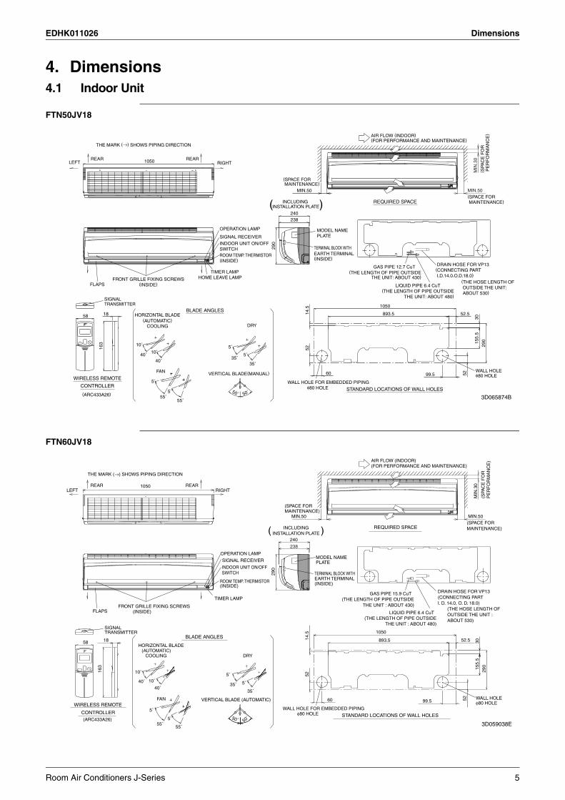
4. Dimensions4.1 Indoor Unit
FTN50JV18
FTN60JV18
AIR FLOW (INDOOR)(FOR PERFORMANCE AND MAINTENANCE)
THE MARK (→) SHOWS PIPING DIRECTION
REARREAR 1050LEFT RIGHT
MIN
.30
( SPA
CE
FO
R P
ER
FO
RM
AN
CE
)
(SPACE FOR MAINTENANCE)
MIN.50 MIN.50(SPACE FOR MAINTENANCE) REQUIRED SPACEINCLUDING
INSTALLATION PLATE)(240238
OPERATION LAMP MODEL NAMEPLATESIGNAL RECEIVER
INDOOR UNIT ON/OFFSWITCH 29
0
ROOM TEMP. THERMISTOR(INSIDE)
TERMINAL BLOCK WITHEARTH TERMINAL(INSIDE)
DRAIN HOSE FOR VP13(CONNECTING PART I.D.14.0,O.D.18.0)
GAS PIPE 12.7 CuTTIMER LAMP (THE LENGTH OF PIPE OUTSIDE
THE UNIT: ABOUT 430)HOME LEAVE LAMPFRONT GRILLE FIXING SCREWS(INSIDE)
(THE HOSE LENGTH OF OUTSIDE THE UNIT: ABOUT 530)
FLAPS LIQUID PIPE 6.4 CuT(THE LENGTH OF PIPE OUTSIDE
THE UNIT: ABOUT 480)
1050
SIGNAL TRANSMITTER
BLADE ANGLES 14.5
52.5893.51858 30
HORIZONTAL BLADE(AUTOMATIC)
COOLING DRY
155.
5
290
10˚
163
5˚ 52
10˚40˚ 5˚35˚
40˚35˚
FAN 60 52VERTICAL BLADE(MANUAL) 99.5WALL HOLE φ80 HOLE
5˚ WALL HOLE FOR EMBEDDED PIPINGWIRELESS REMOTE
CONTROLLER φ80 HOLE STANDARD LOCATIONS OF WALL HOLES50˚5˚ 50˚(ARC433A26) 55˚55˚
3D065874B
(ARC433A26)
FAN
MODEL NAMEPLATE
HORIZONTAL BLADE(AUTOMATIC)
BLADE ANGLES
TERMINAL BLOCK WITHEARTH TERMINAL
SIGNALTRANSMITTER
(INSIDE)
COOLING
(INSIDE)
DRY
VERTICAL BLADE (AUTOMATIC)WIRELESS REMOTE
THE MARK (→) SHOWS PIPING DIRECTION
LEFTREAR 1050
INDOOR UNIT ON/OFFSWITCH
OPERATION LAMP
TIMER LAMP
SIGNAL RECEIVER
RIGHT
58
163
18
10˚
40˚ 10˚
40˚
50˚
5˚
35˚
50˚
5˚
55˚
FLAPS (INSIDE)
CONTROLLER
5˚
35˚
5˚
55˚
238
290
240
( )INCLUDINGINSTALLATION PLATE
REAR
FRONT GRILLE FIXING SCREWS
ROOM TEMP. THERMISTOR
(SPACE FORMAINTENANCE)
MIN.50 MIN.50
MIN
.30
(SPACE FORMAINTENANCE)
(FOR PERFORMANCE AND MAINTENANCE)
REQUIRED SPACE
(SPA
CE
FO
RP
ER
FO
RM
AN
CE
)AIR FLOW (INDOOR)
GAS PIPE 15.9 CuT
LIQUID PIPE 6.4 CuT
WALL HOLE FOR EMBEDDED PIPING
5214
.5
60
1050
893.5
WALL HOLE
155.
5
52
30
290
STANDARD LOCATIONS OF WALL HOLES
φ80 HOLE
φ80 HOLE
THE UNIT : ABOUT 430)(THE LENGTH OF PIPE OUTSIDE
52.5
(THE LENGTH OF PIPE OUTSIDETHE UNIT : ABOUT 480)
99.5
ABOUT 530)
(CONNECTING PARTI. D. 14.0, O. D. 18.0)
DRAIN HOSE FOR VP13
(THE HOSE LENGTH OFOUTSIDE THE UNIT :
3D059038E
Room Air Conditioners J-Series 5
Dimensions EDHK011026
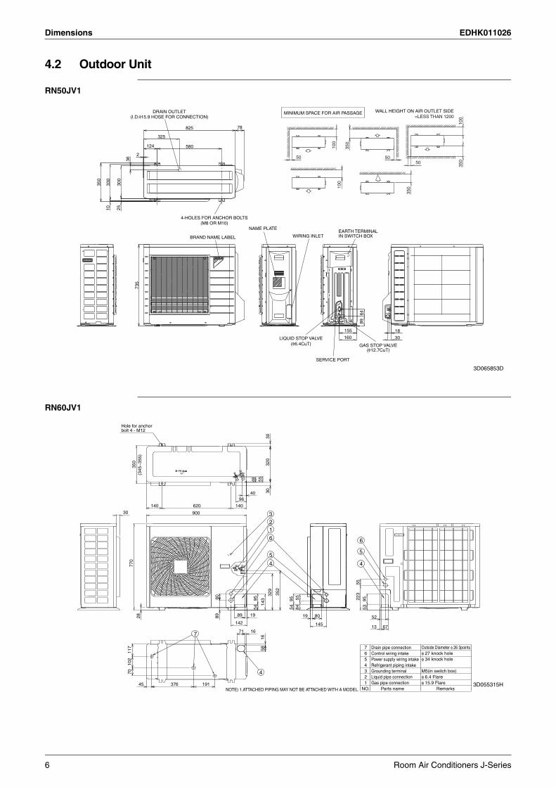
4.2 Outdoor Unit
RN50JV1
RN60JV1
MINIMUM SPACE FOR AIR PASSAGE WALL HEIGHT ON AIR OUTLET SIDE=LESS THAN 1200
DRAIN OUTLET(I.D.φ15.9 HOSE FOR CONNECTION)
100
78825
325
124 580 100
350
2 50 5036 50
350
300
350
330
100
350
2510
4-HOLES FOR ANCHOR BOLTS(M8 OR M10)
NAME PLATE EARTH TERMINAL IN SWITCH BOXBRAND NAME LABEL WIRING INLET
735
6489
18155
30160LIQUID STOP VALVE(φ6.4CuT) GAS STOP VALVE
(φ12.7CuT)
SERVICE PORT
3D065853D
7
145
223
3
1919
143
4
84
620
70
900
95
142
352
52
55
89
320
329
1
48
4
96
54
376
30
95
16
30
55
5
140
71
6089
40
95
6
55
53
191
102
bolt 4 - M12Hole for anchor
350
45
67
140
58
5
16
2
30
117
6
28 80
4
13
54
770
φ 6.4 Flare
NOTE) 1.ATTACHED PIPING MAY NOT BE ATTACHED WITH A MODEL.
M5(in switch box)
(345
~35
5)
φ 15.9 FlareNO.
4
6
32
7
5
1 Gas pipe connection
Power supply wiring intake
Grounding terminal
Drain pipe connection
Liquid pipe connection
Control wiring intake
Refrigerant piping intake
Parts name
Outside Diameter φ 26 3points
φ 34 knock holeφ 27 knock hole
Remarks3D055315H
6 Room Air Conditioners J-Series

EDHK011026 Wiring Diagrams
5. Wiring Diagrams5.1 Indoor Unit
FTN50/60JV18
MM
2
1
3
3.15AFu
X1M
RECTIFIER
S1W
OUTDOOR
RECEIVERSIGNAL
LED1
H1P H2P
LED2
FIELD WIRING.
INDOOR
7
S32
S21
t˚
RED
RE
D
PN
K
5
R2T
H2
t˚
M1S
6
BLK
BLU
BLU
YLW
CONTROLLERREMOTE
WIRELESS
1
PCB1
SA1
RE
D
1S28
OR
G
1
FG
S6
S37
S29
YLW
V2
2
YLW
OR
G
3
M2S
S8
RED
H3
M1F
M
R1T
WHT
PCB4
S1
/
ORG
V1
BRN
WHT
PCB3
PCB2
1
BLU
S38
GRN
H1
MR2
BR
N
S27 S26
PN
K
~ ~
FGFu
H1P, H2PM1FM1S, M2S
PCB1~PCB4R1T, R2TS1~S38S1W
X1M
: SWING MOTOR
: THERMISTOR
: PROTECTIVE EARTH
THE MAIN POWER SUPPLY IS
ON AGAIN.TURNED OFF AND THEN BACK
NOTE THAT OPERATION WILLRESTART AUTOMATICALLY IF
CAUTION
: FRAME GROUND: FUSE
: PILOT LAMP: FAN MOTOR
: PRINTED CIRCUIT BOARD
: CONNECTOR: OPERATION SWITCH
: TERMINAL STRIP
MR2 : MAGNETIC RELAY
SA1 : SURGE ARRESTERV1, V2 : VARISTOR
H1~H3 : HARNESS
3D058895D
Room Air Conditioners J-Series 7
Wiring Diagrams EDHK011026
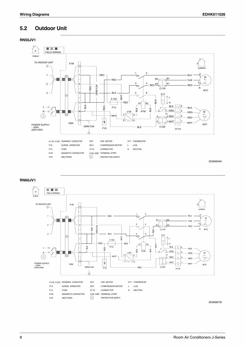
5.2 Outdoor Unit
RN50JV1
RN60JV1
FIELD WIRING
indoor
TO INDOOR UNIT X1M
outdoor
1 2 CBLURED11M
B1B2 1~RED YLWS3 4 A2 A122 REDREDRC11R
M1CRE
D5 6BLK33 S1TG
RN
/YLW
L3.15A W
HT
HBLKRED A1 A2L
6BLKF1UL t° BLKBLK
LRE
D
ORG 4CK1MV1R MBLK
BLK
NN ORGH4 1~1
3WHT RED4 3 RED2 3 12 1 WHT
X2M WHTM1F
C12RGRN/YLW BLKF1S X11A
POWER SUPPLY~ 50Hz220V-240V
S1T
L
N
: THERMOSTAT
: LIVE
: NEUTRAL
M1F
M1C
X11A
X1M, X2M
: FAN MOTOR
: COMPRESSOR MOTOR
: CONNECTOR
: TERMINAL STRIP
: PROTECTIVE EARTH
C11R, C12R
F1S
F1U
K1M
V1R
: RUNNING CAPACITOR
: SURGE ARRESTER
: FUSE
: MAGNETIC CONTACTOR
: RECTIFIER
3D066609A
FIELD WIRINGindoor
TO INDOOR UNIT X1M
outdoor
1 2 CBLURED11M
B2B1 1~YLWS3 4 A1 A222
REDRC11R M1C
RE
D
RE
D
5 6BLK33S1T
GR
N/Y
LW
L3.15A W
HT
HRED RED A1 A2L
BLK 6WH
T
F1UL t° BLKBLK
LRE
D
ORGC 4BLK
BLK K1M
V1R MNN ORGH2 4 1~
3WHT 2 REDRED
1 3 11 WHTX2M WHT M1F
C12RGRN/YLW REDF1S X11A
POWER SUPPLY~ 50Hz220V-240V
S1T: RUNNING CAPACITOR : FAN MOTOR
L: SURGE ARRESTER : COMPRESSOR MOTOR
N
: THERMOSTAT
: LIVE
: NEUTRAL: FUSE : CONNECTOR
: MAGNETIC CONTACTOR : TERMINAL STRIP
M1F
M1C
X11A
X1M, X2M
: PROTECTIVE EARTH
C11R, C12R
F1S
F1U
K1M
V1R : RECTIFIER
3D066807B
8 Room Air Conditioners J-Series

EDHK011026 Piping Diagrams
6. Piping Diagrams6.1 Indoor Unit
6.2 Outdoor Unit
FTN50JV18 FTN60JV18
FIELD PIPING
(6.4CuT)
FIELD PIPING
(12.7CuT)
CROSS FLOW FAN
FAN MOTOR
(7.9CuT)
INDOOR UNIT
(12.7CuT)
M
HEAT EXCHANGER
REFRIGERANT FLOW
THERMISTORON HEAT EXCH.
COOLING
4D051010F
INDOOR UNIT
(7.9CuT)
HEAT EXCHANGER
THERMISTORON HEAT EXCH.
CROSS FLOW FANFIELD PIPING
(6.4CuT) MFAN MOTOR
FIELD PIPING
(15.9CuT) (12.7CuT)
REFRIGERANT FLOWCOOLING
4D051016M
RN50JV1 RN60JV1
OUTDOOR UNIT
OUTDOOR TEMPERATUREHEAT EXCHANGERTHERMISTER
6.4CuT
FILT
ER
9.5C
uT
LIQUID STOPVALVEM FIELD PIPING
(6.4CuT)6.4C
uT
6.4CuT
CAPILLARY TUBEPROPELLER FAN
12.7CuT 12.7CuTFIELD PIPING(12.7CuT)
MUFFLER GAS STOP VALVEWITH SERVICE PORT
ACCUMULATOR
COMPRESSOR
REFRIGERANT FLOWCOOLING
4D065584B
OUTDOOR UNIT
HEAT EXCHANGER
6.4C
uT
MUF
FLER
M LIQUID STOPVALVE FIELD PIPING
(6.4CuT)6.4CuTPROPELLER FAN
FILT
ER
CAPILLARY TUBE
MUFFLER15.9CuTFIELD PIPING(15.9CuT)
12.7CuT 12.7CuT
9.5C
uT
GAS STOP VALVEWITH SERVICE PORT
ACCUMULATOR
COMPRESSOR
REFRIGERANT FLOWCOOLING
4D065585B
Room Air Conditioners J-Series 9
Capacity Tables EDHK011026
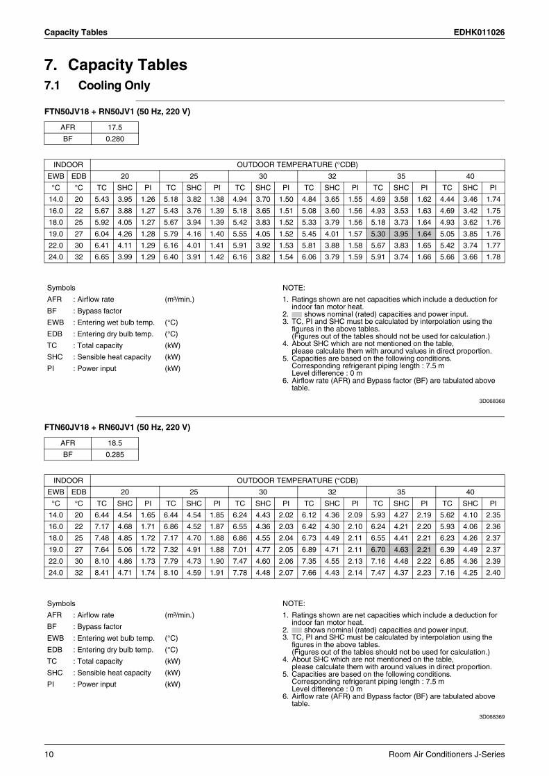
7. Capacity Tables7.1 Cooling Only
FTN50JV18 + RN50JV1 (50 Hz, 220 V)
3D068368
FTN60JV18 + RN60JV1 (50 Hz, 220 V)
3D068369
AFR 17.5
BF 0.280
INDOOR OUTDOOR TEMPERATURE (°CDB)
EWB EDB 20 25 30 32 35 40
°C °C TC SHC PI TC SHC PI TC SHC PI TC SHC PI TC SHC PI TC SHC PI
14.0 20 5.43 3.95 1.26 5.18 3.82 1.38 4.94 3.70 1.50 4.84 3.65 1.55 4.69 3.58 1.62 4.44 3.46 1.74
16.0 22 5.67 3.88 1.27 5.43 3.76 1.39 5.18 3.65 1.51 5.08 3.60 1.56 4.93 3.53 1.63 4.69 3.42 1.75
18.0 25 5.92 4.05 1.27 5.67 3.94 1.39 5.42 3.83 1.52 5.33 3.79 1.56 5.18 3.73 1.64 4.93 3.62 1.76
19.0 27 6.04 4.26 1.28 5.79 4.16 1.40 5.55 4.05 1.52 5.45 4.01 1.57 5.30 3.95 1.64 5.05 3.85 1.76
22.0 30 6.41 4.11 1.29 6.16 4.01 1.41 5.91 3.92 1.53 5.81 3.88 1.58 5.67 3.83 1.65 5.42 3.74 1.77
24.0 32 6.65 3.99 1.29 6.40 3.91 1.42 6.16 3.82 1.54 6.06 3.79 1.59 5.91 3.74 1.66 5.66 3.66 1.78
Symbols NOTE:
AFR : Airflow rate (m³/min.) 1. Ratings shown are net capacities which include a deduction for indoor fan motor heat.
2. shows nominal (rated) capacities and power input.3. TC, PI and SHC must be calculated by interpolation using the
figures in the above tables.(Figures out of the tables should not be used for calculation.)
4. About SHC which are not mentioned on the table, please calculate them with around values in direct proportion.
5. Capacities are based on the following conditions.Corresponding refrigerant piping length : 7.5 mLevel difference : 0 m
6. Airflow rate (AFR) and Bypass factor (BF) are tabulated above table.
BF : Bypass factor
EWB : Entering wet bulb temp. (°C)
EDB : Entering dry bulb temp. (°C)
TC : Total capacity (kW)
SHC : Sensible heat capacity (kW)
PI : Power input (kW)
AFR 18.5
BF 0.285
INDOOR OUTDOOR TEMPERATURE (°CDB)
EWB EDB 20 25 30 32 35 40
°C °C TC SHC PI TC SHC PI TC SHC PI TC SHC PI TC SHC PI TC SHC PI
14.0 20 6.44 4.54 1.65 6.44 4.54 1.85 6.24 4.43 2.02 6.12 4.36 2.09 5.93 4.27 2.19 5.62 4.10 2.35
16.0 22 7.17 4.68 1.71 6.86 4.52 1.87 6.55 4.36 2.03 6.42 4.30 2.10 6.24 4.21 2.20 5.93 4.06 2.36
18.0 25 7.48 4.85 1.72 7.17 4.70 1.88 6.86 4.55 2.04 6.73 4.49 2.11 6.55 4.41 2.21 6.23 4.26 2.37
19.0 27 7.64 5.06 1.72 7.32 4.91 1.88 7.01 4.77 2.05 6.89 4.71 2.11 6.70 4.63 2.21 6.39 4.49 2.37
22.0 30 8.10 4.86 1.73 7.79 4.73 1.90 7.47 4.60 2.06 7.35 4.55 2.13 7.16 4.48 2.22 6.85 4.36 2.39
24.0 32 8.41 4.71 1.74 8.10 4.59 1.91 7.78 4.48 2.07 7.66 4.43 2.14 7.47 4.37 2.23 7.16 4.25 2.40
Symbols NOTE:
AFR : Airflow rate (m³/min.) 1. Ratings shown are net capacities which include a deduction for indoor fan motor heat.
2. shows nominal (rated) capacities and power input.3. TC, PI and SHC must be calculated by interpolation using the
figures in the above tables.(Figures out of the tables should not be used for calculation.)
4. About SHC which are not mentioned on the table, please calculate them with around values in direct proportion.
5. Capacities are based on the following conditions.Corresponding refrigerant piping length : 7.5 mLevel difference : 0 m
6. Airflow rate (AFR) and Bypass factor (BF) are tabulated above table.
BF : Bypass factor
EWB : Entering wet bulb temp. (°C)
EDB : Entering dry bulb temp. (°C)
TC : Total capacity (kW)
SHC : Sensible heat capacity (kW)
PI : Power input (kW)
10 Room Air Conditioners J-Series
EDHK011026 Capacity Tables
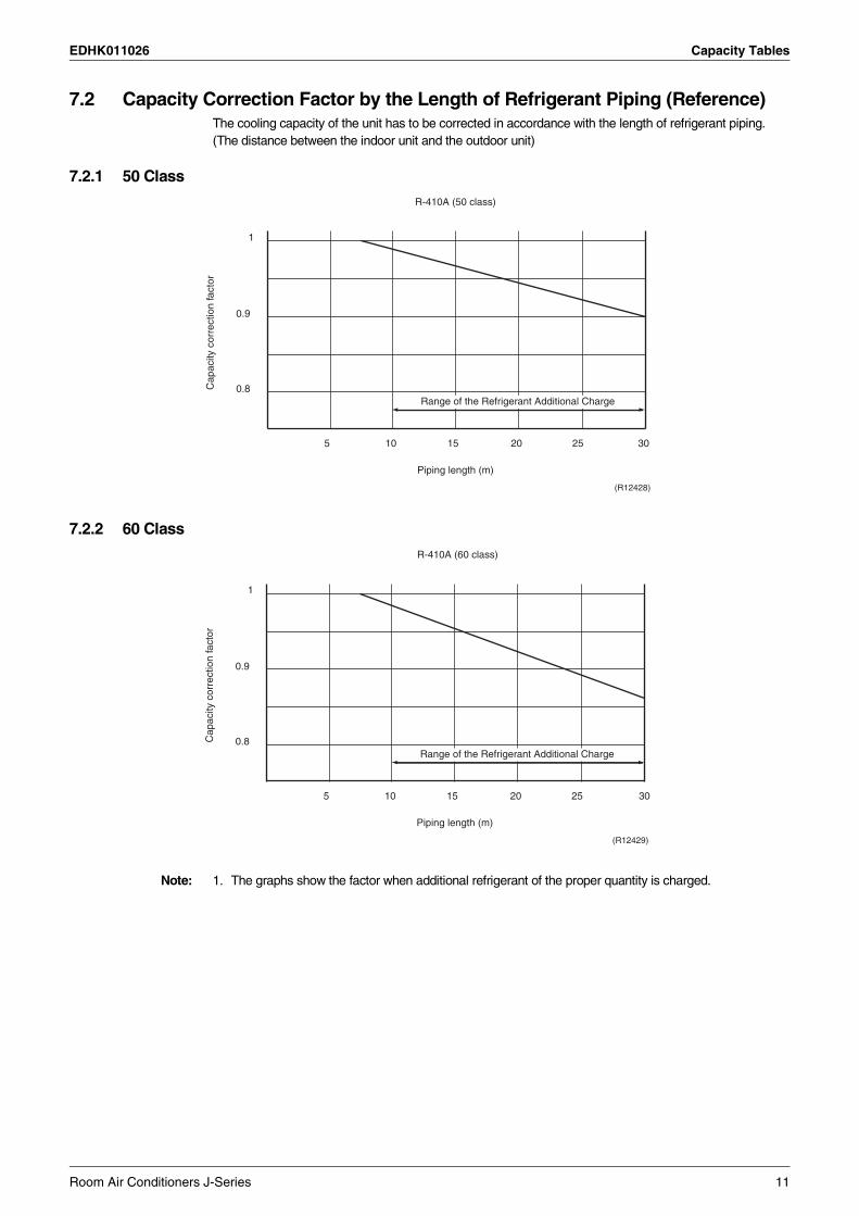
7.2 Capacity Correction Factor by the Length of Refrigerant Piping (Reference)The cooling capacity of the unit has to be corrected in accordance with the length of refrigerant piping. (The distance between the indoor unit and the outdoor unit)
7.2.1 50 Class
7.2.2 60 Class
Note: 1. The graphs show the factor when additional refrigerant of the proper quantity is charged.
Cap
acity
cor
rect
ion
fact
or
1
5 10 15 20 25 30
0.9
0.8
R-410A (50 class)
Piping length (m)
(R12428)
Range of the Refrigerant Additional Charge
Cap
acity
cor
rect
ion
fact
or
1
5 10 15 20 25 30
0.9
0.8
R-410A (60 class)
Piping length (m)
(R12429)
Range of the Refrigerant Additional Charge
Room Air Conditioners J-Series 11

Operation Limit EDHK011026
8. Operation Limit
RN50/60JV1
50
46
40
30O
utdo
or te
mp.
(˚C
DB
)
Pul
l-dow
n pe
riod
Con
tinuo
us o
pera
tion
2019.4
0
14 302310 20 28Notes: Indoor temp. (˚CWB)The graph is based
on the following conditions.• Equivalent piping length 7.5m• Level difference 0m• Air flow rate High
4D063906C
12 Room Air Conditioners J-Series

EDHK011026 Sound Level
9. Sound Level9.1 Measuring Location
Note: 1. Operation sound is measured in an anechoic chamber.2. The data are based on the conditions shown in the table below.
Indoor Unit Outdoor Unit
1 m
0.8
m
(R1759)
1 m
(R1003)
Cooling Piping LengthIndoor ; 27°CDB / 19°CWB
Outdoor ; 35°CDB / 24°CWB 5 m
Room Air Conditioners J-Series 13
Sound Level EDHK011026
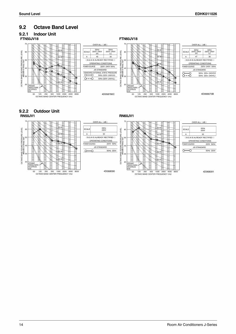
9.2 Octave Band Level9.2.1 Indoor Unit
9.2.2 Outdoor Unit
FTN50JV18 FTN60JV18
NC-60
NC-50
NC-40
NC-20
NC-30
POWER SOURCE
JIS STANDARD
OPERATING CONDITIONS
OC
TAV
E B
AN
D S
OU
ND
PR
ES
SU
RE
LE
VE
LdB
( 0dB
=0.
0002
µ ba
r)
70
60
20
30
50
40
THRESHOLD HEARINGAPPROXIMATE
FOR CONTINUOUSNOISE
63 125OCTAVE BAND CENTER FREQUENCY (Hz)
250 500 1000 2000 4000 8000
OVER ALL ( dB )
SCALE
A
( B.G.N IS ALREADY RECTIFIED )
220V~240V50Hz
45 35
STANDARD EXTERNAL STATIC PRESSURE
50Hz 220V~240V(L)
(H)220V~240V
50Hz
50Hz 220V~240V(H)
220V~240V 50Hz
(L)
4D058780C
POWER SOURCE
JIS STANDARD
OPERATING CONDITIONS
OC
TAV
E B
AN
D S
OU
ND
PR
ES
SU
RE
LE
VE
LdB
( 0dB
=0.
0002
µ ba
r)
70
60
20
30
50
40
THRESHOLD HEARINGAPPROXIMATE
FOR CONTINUOUSNOISE
63 125OCTAVE BAND CENTER FREQUENCY (Hz)
250 500 1000 2000 4000 8000
OVER ALL ( dB )
SCALE
A
( B.G.N IS ALREADY RECTIFIED )
NC-60
NC-50
NC-40
NC-30
NC-20
50Hz220V~240V
(H)
50Hz220V~240V
(L)
3647
220V~240V 50Hz
50Hz 220v~240V(H)
50Hz 220v~240V(L)
4D066673B
RN50JV1 RN60JV1
POWER SOURCE
JIS STANDARD
OPERATING CONDITIONS
OC
TAV
E B
AN
D S
OU
ND
PR
ES
SU
RE
LE
VE
LdB
( 0dB
=0.
0002
µ ba
r)
70
60
20
30
50
40
THRESHOLD HEARINGAPPROXIMATE
FOR CONTINUOUSNOISE
63 125OCTAVE BAND CENTER FREQUENCY (Hz)
250 500 1000 2000 4000 8000
OVER ALL ( dB )
SCALE
A
( B.G.N IS ALREADY RECTIFIED )
NC-60
NC-50
NC-40
NC-30
NC-20
50Hz220V
50
220V 50Hz
50Hz 220V
4D068090
POWER SOURCE
JIS STANDARD
OPERATING CONDITIONS
OC
TAV
E B
AN
D S
OU
ND
PR
ES
SU
RE
LE
VE
LdB
( 0dB
=0.
0002
µ ba
r)70
60
20
30
50
40
THRESHOLD HEARINGAPPROXIMATE
FOR CONTINUOUSNOISE
63 125OCTAVE BAND CENTER FREQUENCY (Hz)
250 500 1000 2000 4000 8000
OVER ALL ( dB )
SCALE
A
( B.G.N IS ALREADY RECTIFIED )
NC-60
NC-50
NC-40
NC-30
NC-20
50Hz220V
52
220V 50Hz
50Hz 220V
4D068091
14 Room Air Conditioners J-Series
EDHK011026 Electric Characteristics
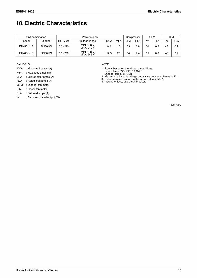
10.Electric Characteristics
3D067567B
Unit combination Power supply Compressor OFM IFM
Indoor Outdoor Hz - Volts Voltage range MCA MFA LRA RLA W FLA W FLA
FTN50JV18 RN50JV1 50 - 220 MIN. 198 VMAX. 242 V 9.2 15 33 6.8 50 0.5 43 0.2
FTN60JV18 RN60JV1 50 - 220 MIN. 198 VMAX. 242 V 12.5 25 54 9.4 65 0.6 43 0.2
SYMBOLS: NOTE:
MCA : Min. circuit amps (A) 1. RLA is based on the following conditions.Indoor temp. 27°CDB / 19°CWBOutdoor temp. 35°CDB.
2. Maximum allowable voltage unbalance between phases is 2%.3. Select wire size based on the larger value of MCA.4. Instead of fuse, use circuit breaker.
MFA : Max. fuse amps (A)
LRA : Locked rotor amps (A)
RLA : Rated load amps (A)
OFM : Outdoor fan motor
IFM : Indoor fan motor
FLA : Full load amps (A)
W : Fan motor rated output (W)
Room Air Conditioners J-Series 15

Installation Manual EDHK011026
11. Installation Manual11.1 Safety Precautions
16 Room Air Conditioners J-Series
EDHK011026 Installation Manual
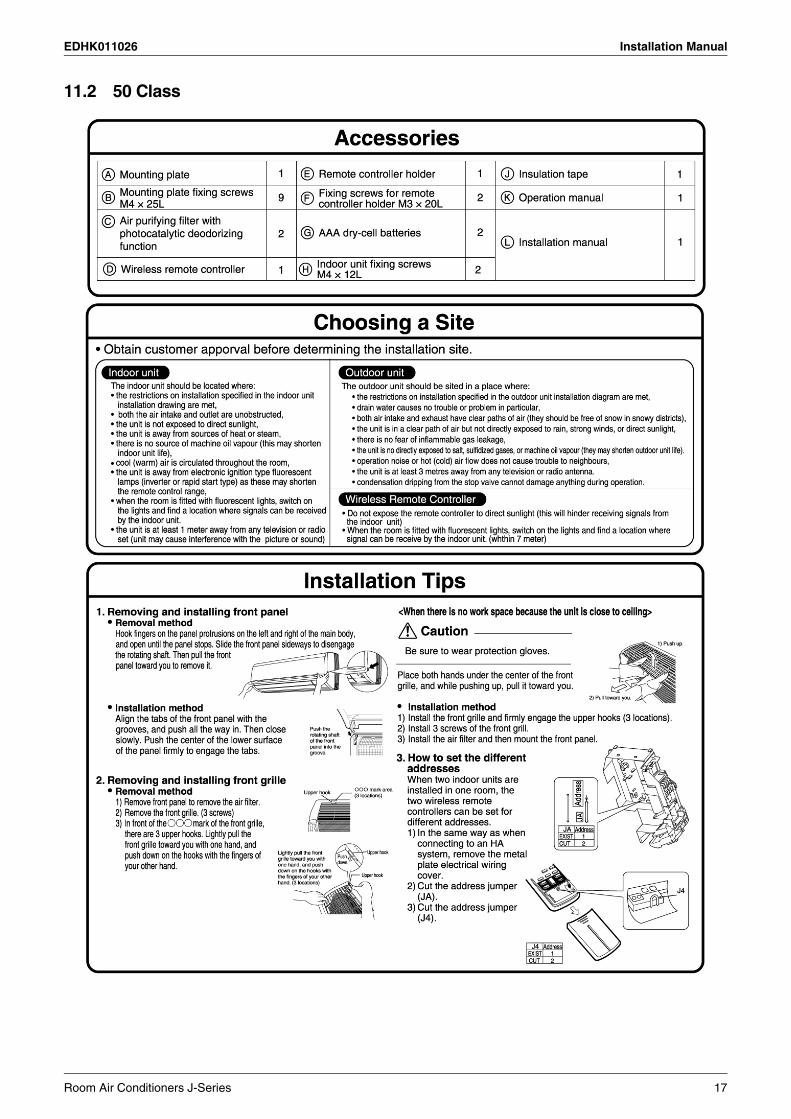
11.2 50 Class
Room Air Conditioners J-Series 17

Installation Manual EDHK011026
18 Room Air Conditioners J-Series

EDHK011026 Installation Manual
Indoor/outdoor Unit Installation Drawings
Room Air Conditioners J-Series 19
Installation Manual EDHK011026
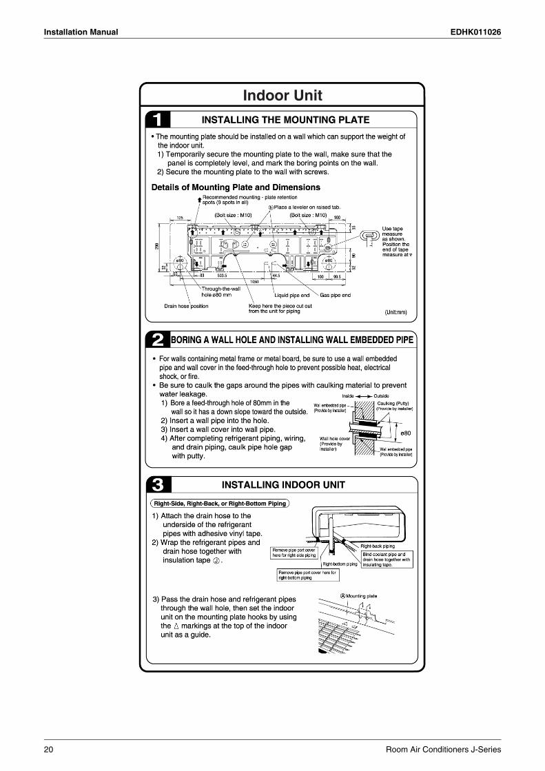
20 Room Air Conditioners J-Series

EDHK011026 Installation Manual
Room Air Conditioners J-Series 21
Installation Manual EDHK011026
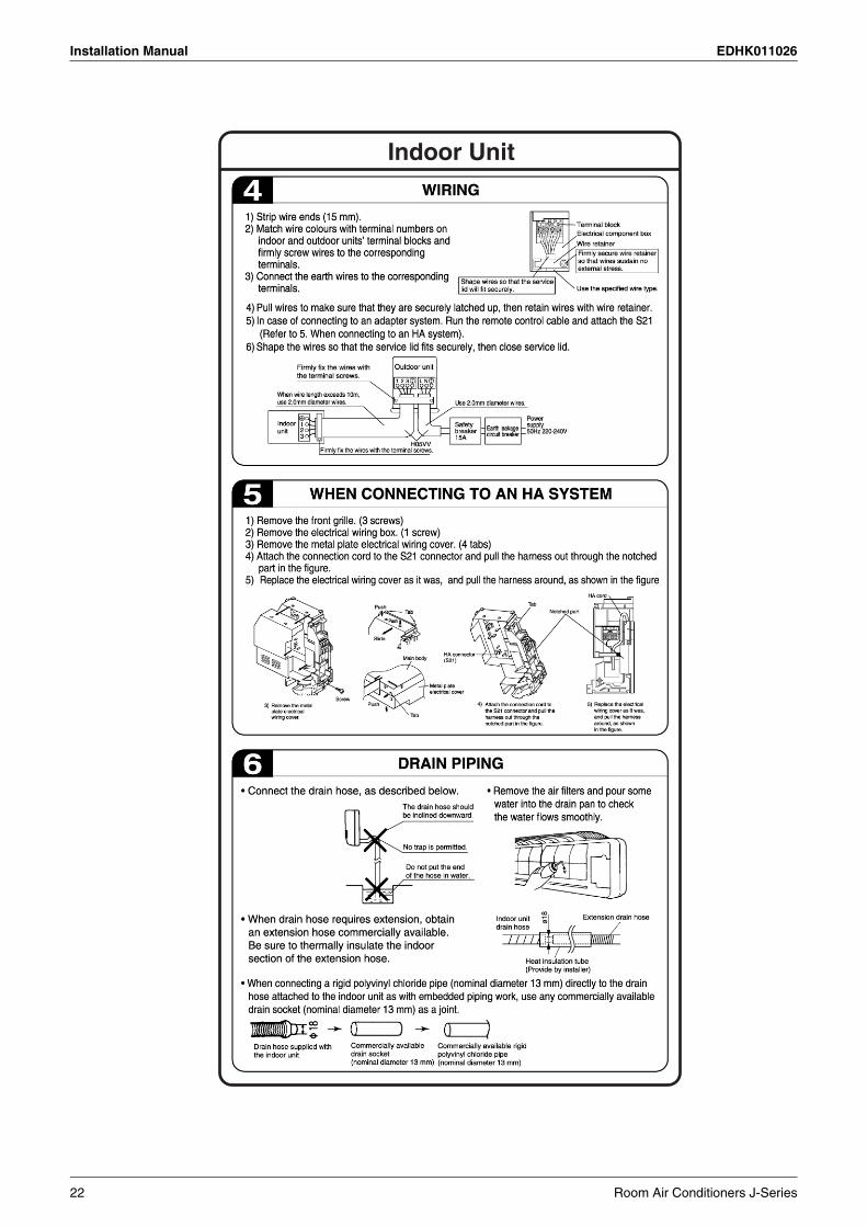
22 Room Air Conditioners J-Series
EDHK011026 Installation Manual
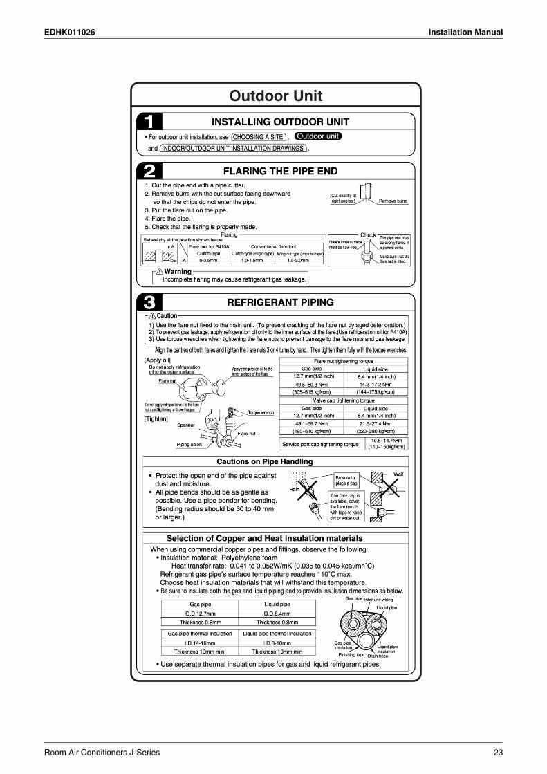
Room Air Conditioners J-Series 23

Installation Manual EDHK011026
24 Room Air Conditioners J-Series

EDHK011026 Installation Manual
3PN10898-2G
Room Air Conditioners J-Series 25

Installation Manual EDHK011026
11.3 60 Class
26 Room Air Conditioners J-Series

EDHK011026 Installation Manual
Indoor/outdoor Unit Installation Drawings
Room Air Conditioners J-Series 27

Installation Manual EDHK011026
Indoor/outdoor Unit Installation Drawings
28 Room Air Conditioners J-Series
EDHK011026 Installation Manual
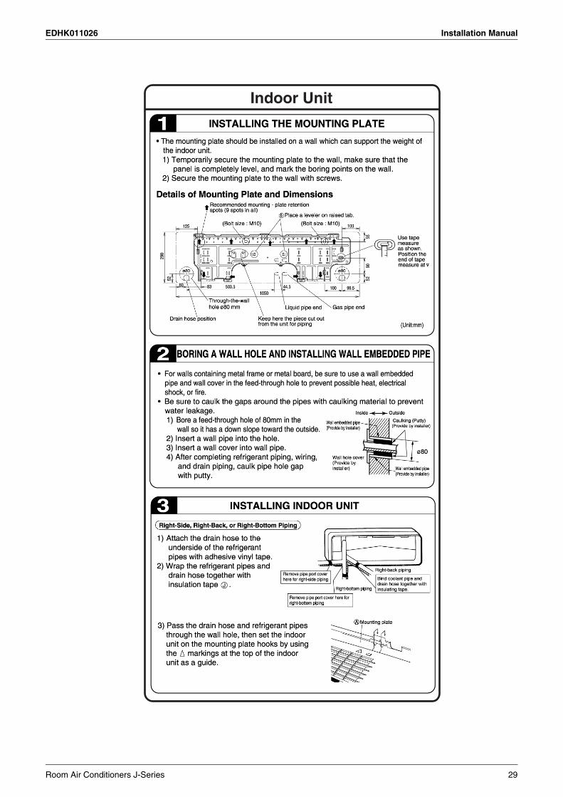
Room Air Conditioners J-Series 29

Installation Manual EDHK011026
30 Room Air Conditioners J-Series
EDHK011026 Installation Manual
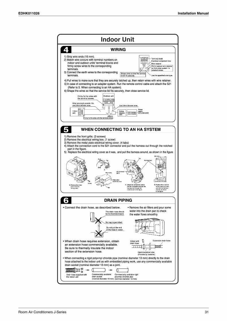
Room Air Conditioners J-Series 31
Installation Manual EDHK011026
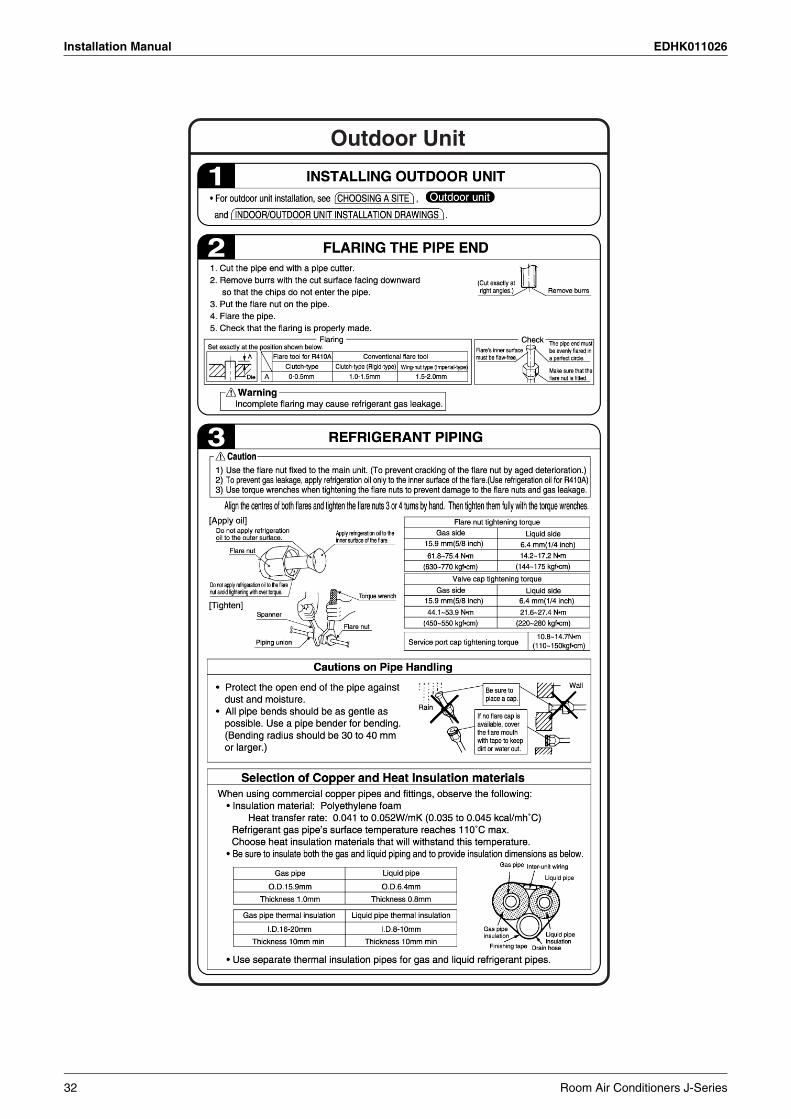
32 Room Air Conditioners J-Series

EDHK011026 Installation Manual
Room Air Conditioners J-Series 33

Installation Manual EDHK011026
3PN10898-4G
34 Room Air Conditioners J-Series

EDHK011026 Operation Manual
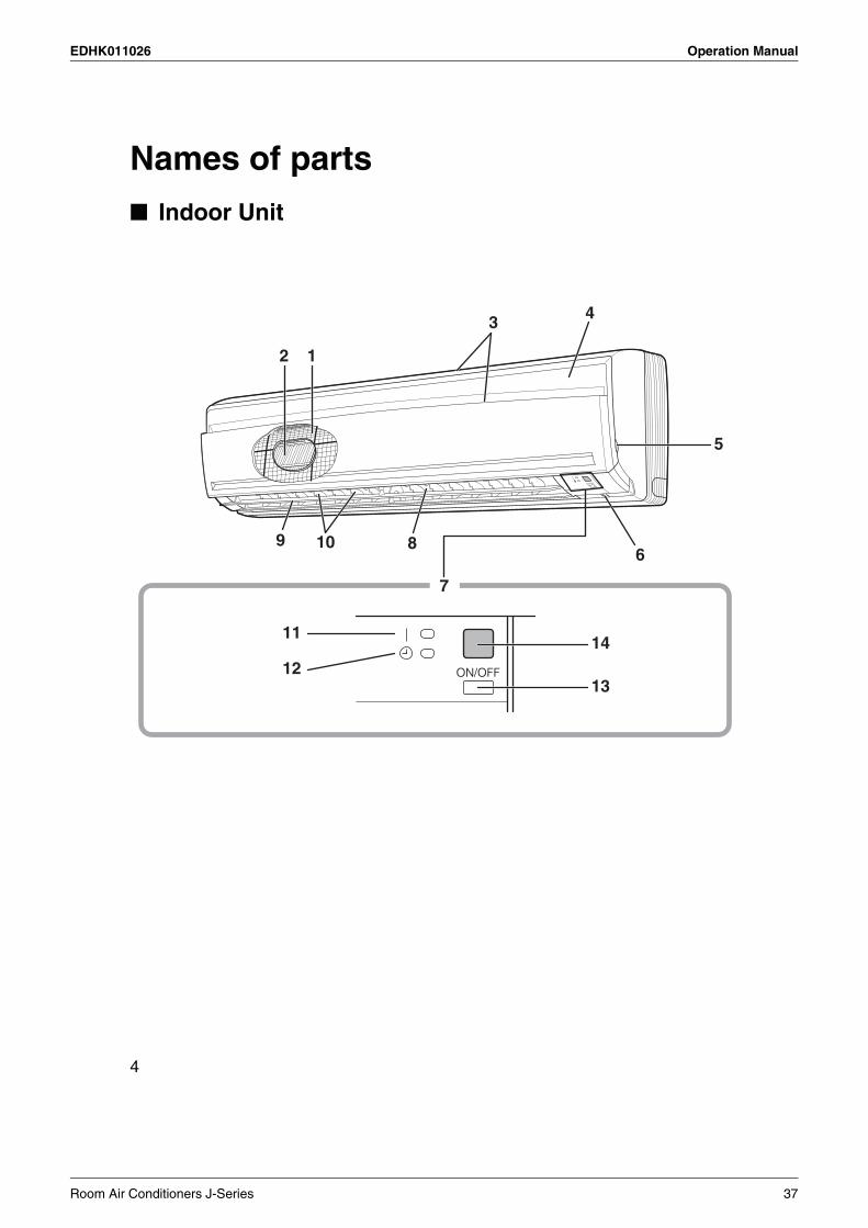
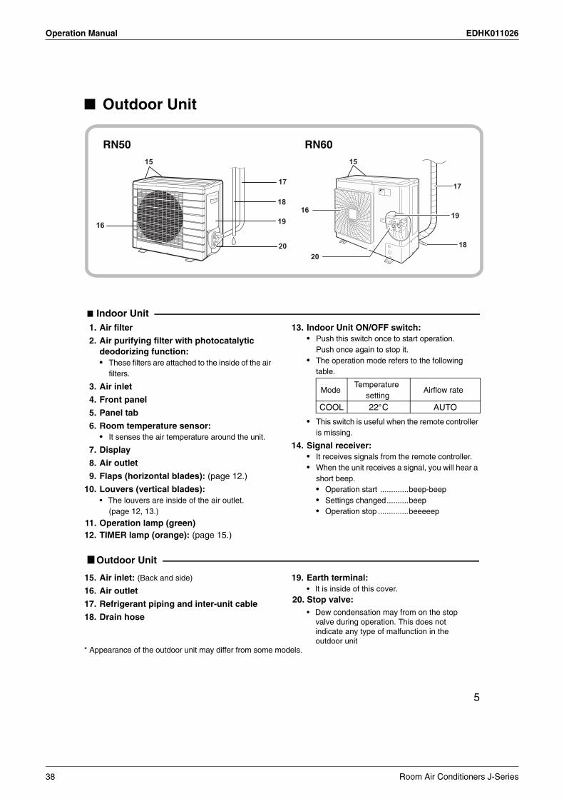
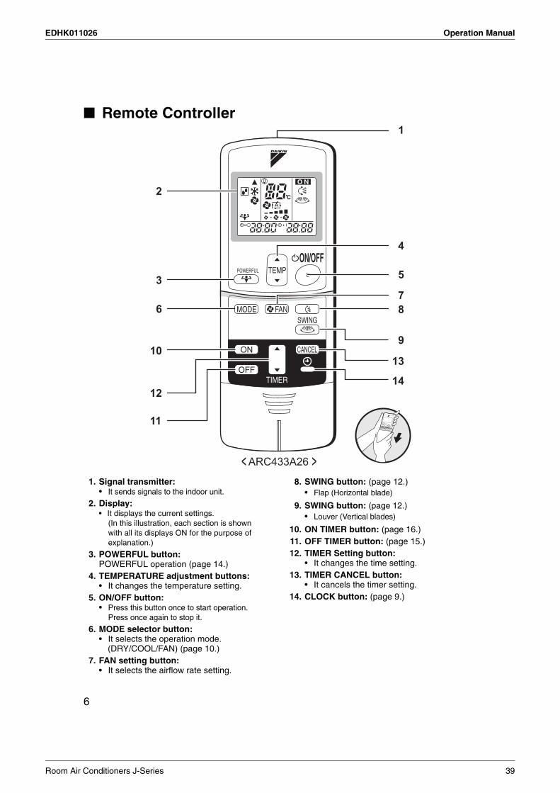
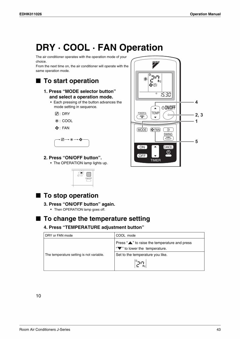
12.Operation Manual
Room Air Conditioners J-Series 35
Operation Manual EDHK011026
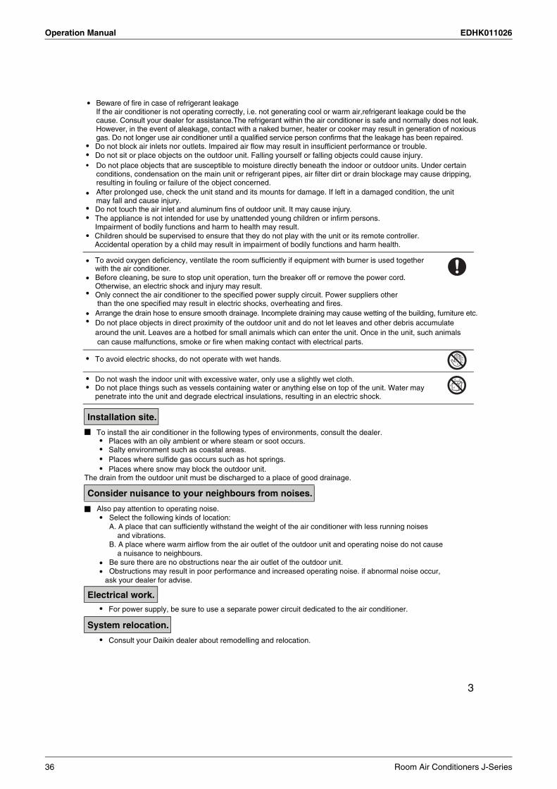
36 Room Air Conditioners J-Series
EDHK011026 Operation Manual
Room Air Conditioners J-Series 37
Operation Manual EDHK011026
38 Room Air Conditioners J-Series
EDHK011026 Operation Manual
Room Air Conditioners J-Series 39

Operation Manual EDHK011026
40 Room Air Conditioners J-Series

EDHK011026 Operation Manual
Room Air Conditioners J-Series 41

Operation Manual EDHK011026
42 Room Air Conditioners J-Series
EDHK011026 Operation Manual
Room Air Conditioners J-Series 43
Operation Manual EDHK011026
44 Room Air Conditioners J-Series
EDHK011026 Operation Manual
Room Air Conditioners J-Series 45

Operation Manual EDHK011026
46 Room Air Conditioners J-Series

EDHK011026 Operation Manual
Room Air Conditioners J-Series 47

Operation Manual EDHK011026
48 Room Air Conditioners J-Series

EDHK011026 Operation Manual
Room Air Conditioners J-Series 49
Operation Manual EDHK011026
50 Room Air Conditioners J-Series
EDHK011026 Operation Manual
Room Air Conditioners J-Series 51
Operation Manual EDHK011026
52 Room Air Conditioners J-Series

EDHK011026 Operation Manual
20
Trouble Shooting
The following cases are not air conditioner troubles but have some reasons. You may just continue using it.
These cases are not troubles.
noitanalpxEesaCOperation does not start soon.• When ON/OFF button was
pressed soon afteroperation was stopped.
• When the mode was reselected.
• This is to protect the air conditioner.You should wait for about 3 minutes.
The outdoor unit emits water or steam.
In COOL or DRY mode• Moisture in the air condenses into water on the cool
surface of outdoor unit piping and drips.
Mists come out of the indoorunit.
This happens when the air in the room is cooled into mist by the cold airflow during cooling operation.
The indoor unit gives out odour. This happens when smells of the room, furniture, orcigarettes are absorbed into the unit and discharged with theairflow.(If this happens, we recommend you to have the indoor unit washed by a technician. Consult the service shop where youbought the air conditioner.)
The outdoor fan rotates whilethe air conditioner is not inoperation.
After operation is stopped:• The outdoor fan continues rotating for another 60
seconds for system protection.While the air conditioner is not in operation:• When the outdoor temperature is very high, the outdoor
fan starts rotating for system protection.
The operation stoppedsuddenly.(OPERATION lamp is on.)
For system protection, the air conditioner may stop operating on a sudden large voltage fluctuation.It automatically resumes operation in about 3 minutes.
No remote controller signals are displayed.The remote controller sensitivity
The display is low in contrast or blacked out.The display runs out of control.
A “PISHI-PISHI” squeaking sound is heard when the systemis in operation or after the stop of operation
• The batteries are dying and the remote controller is malfunctioning. Replace all the batteries with new size AAAalkaline batteries. For details, refer to “To set the batteries” of this manual. (page 7.)
* If the reset button is provided, press the reset button after thebatteries are replaced.
is low.
• Expansion and contraction of plastic parts caused by temperature change makes this noise.
Room Air Conditioners J-Series 53
Operation Manual EDHK011026
54 Room Air Conditioners J-Series
EDHK011026 Operation Manual
3PN10897-5D
Room Air Conditioners J-Series 55
Optional Accessories EDHK011026
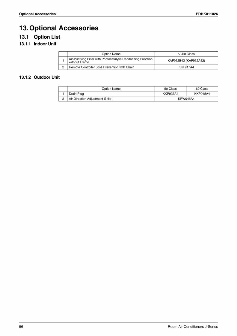
13.Optional Accessories13.1 Option List13.1.1 Indoor Unit
13.1.2 Outdoor Unit
Option Name 50/60 Class
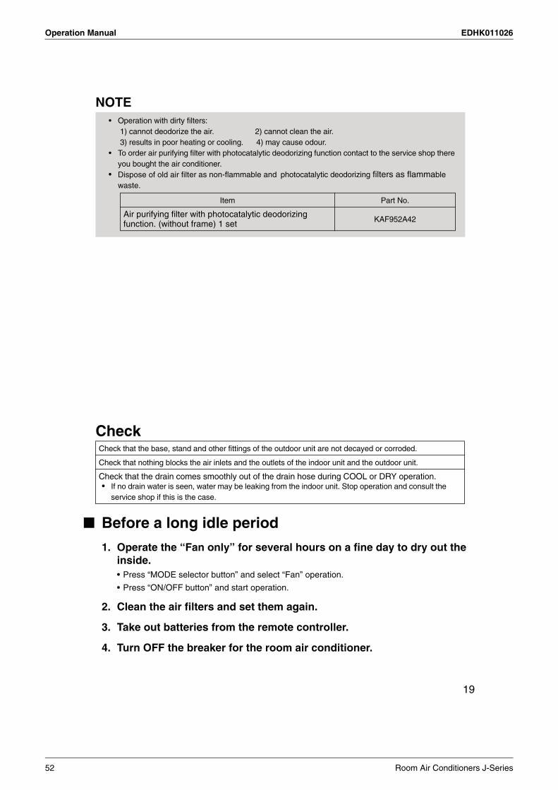
1 Air-Purifying Filter with Photocatalytic Deodorizing Function without Frame KAF952B42 (KAF952A42)
2 Remote Controller Loss Prevention with Chain KKF917A4
Option Name 50 Class 60 Class
1 Drain Plug KKP937A4 KKP945A4
2 Air Direction Adjustment Grille KPW945A4
56 Room Air Conditioners J-Series
EDHK011026 Optional Accessories
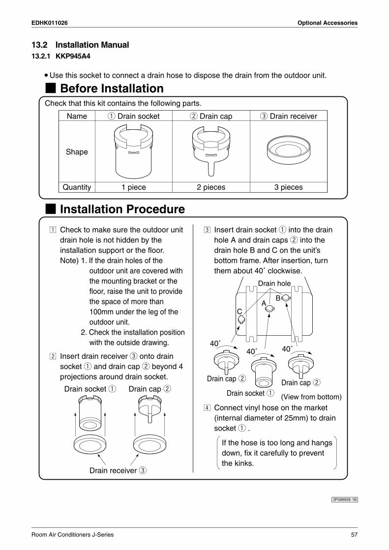
13.2 Installation Manual13.2.1 KKP945A4
3P089958-1B
Room Air Conditioners J-Series 57

Optional Accessories EDHK011026
13.2.2 KPW945A4
Check the following parts
Installation Procedure
Before installation
Name
Quantity
Louver
1piece
Truss tapping screw
M4x4screws(max.7.5kW class)M5x4screws(8.0/9.0kW class)
Installation manual
1piece
Shape
Selection of Installation Location
Installation of Louvers
Space Needed for Installation
Use when installing in a location that meets the following conditions.When installing near the border to a neighbor's houseIf exhaust blows directly on passers-by because outdoor unit is instal-led facing a road.If exhaust blows directly on vegetation
A minimum of 100mm is needed between the back of the outdoor unit and any obstructions(walls, etc.)
more than100
Attach the louvers overlapping the standard grill.Installing the louvers without the grill would allow hands to enter the fan area, which is dangerous, so be sure to install the standard grill.
Caution
When pointing up When pointing down
(1) Remove the 4 attachment screws fromthe standard grill.
Remove the 4 attachment screws fromthe standard grill.
(2) Install the louver pointed up.Overlap the standard grill andscrew both in together.
The attachment screwsare in the louvers.
Install the louver pointed down.Overlap the standard grill andscrew both in together.
The attachment screwsare in the louvers.
(3)
(1)
(2)
(3)Installation complete Installation complete
3P089958-2C
58 Room Air Conditioners J-Series


Warning Daikin Industries, Ltd.’s products are manufactured for export to numerous countries throughout the world. Daikin Industries, Ltd. does not have control over which products are exported to and used in a particular country. Prior to purchase, please therefore confirm with your local authorised importer, distributor and/or retailer whether this product conforms to the applicable standards, and is suitable for use, in the region where the product will be used. This statement does not purport to exclude, restrict or modify the application of any local legislation.
Ask a qualified installer or contractor to install this product. Do not try to install the product yourself. Improper installation can result in water or refrigerant leakage, electrical shock, fire or explosion.
Use only those parts and accessories supplied or specified by Daikin. Ask a qualified installer or contractor to install those parts and accessories. Use of unauthorised parts and accessories or improper installation of parts and accessories can result in water or refrigerant leakage, electrical shock, fire or explosion.
Read the User's Manual carefully before using this product. The User's Manual provides important safety instructions and warnings. Be sure to follow these instructions and warnings.
If you have any enquiries, please contact your local importer, distributor and/or retailer.
1. Air conditioners should not be installed in areas where corrosive gases, such as acid gas or alkaline gas, are produced.2. If the outdoor unit is to be installed close to the sea shore, direct exposure to the sea breeze should be avoided. If you need to install the outdoor unit close to the sea shore, contact your local distributor.
Cautions on product corrosion
JMI-0107 JQA-1452
Organization:DAIKIN INDUSTRIES, LTD.AIR CONDITIONING MANUFACTURING DIVISION
Scope of Registration:THE DESIGN/DEVELOPMENT AND MANUFACTURE OF COMMERCIAL AIR CONDITIONING, HEATING, COOLING, REFRIGERATING EQUIPMENT, COMMERCIAL HEATING EQUIPMENT, RESIDENTIAL AIR CONDITIONING EQUIPMENT, HEAT RECLAIM VENTILATION, AIR CLEANING EQUIPMENT, MARINE TYPE CONTAINER REFRIGERATION UNITS, COMPRESSORS AND VALVES.
Organization:DAIKIN INDUSTRIES(THAILAND) LTD.
Scope of Registration:THE DESIGN/DEVELOPMENTAND MANUFACTURE OF AIR CONDITIONERS AND THE COMPONENTS INCLUDING COMPRESSORS USED FOR THEM
All of the Daikin Group’s business facilities and subsidiaries in Japan are certified under the ISO 14001 international standard for environment management.
DealerHead Office:Umeda Center Bldg., 2-4-12, Nakazaki-Nishi,Kita-ku, Osaka, 530-8323 Japan
Tokyo Office:JR Shinagawa East Bldg., 2-18-1, Konan,Minato-ku, Tokyo, 108-0075 Japan
http://www.daikin.com/global_ac/
EDHK011026Printed in Japan 06/10/0007 FS.AK.B
gy
Specifications, designs and other content appearing in this brochure are current as of June 2010 but subject to change without notice.
All rights reservedc