daewoo electronics co., ltd. · pdf filedaewoo electronics co., ltd. 1 precautions to be...
TRANSCRIPT

DAEWOO ELECTRONICS CO., LTD.686, AHYEON-DONG MAPO-GU SEOUL, KOREAC.P.O. BOX 8003 SEOUL, KOREATELEX: DWELEC K28177-8CABLE: “DAEWOOELEC”E-MAIL : [email protected]: 02) 360-8184TEL: 02) 360-8179~8180
PRINTED DATE: Dec. 1999

Service Manual
Microwave Oven Model :KOG-371G0S KOG-391G0S
KOG-371H0S KOG-391H0SKOG-376T1S KOG-396T1SKOG-371R0S KOG-391R0SKOG-374R0S KOG-375R0SKOG-373R0S KOG-393R0S
DAEWOO ELECTRONICS CO., LTD.
11
PRECAUTIONS TO BE OBSERVED BEFORE ANDDURING SERVICING TO AVOID POSSIBLE EXPOSURETO EXCESSIVE MICROWAVE ENERGY(a) Do not operate or allow the oven to be operated with the door open.
(b) Make the following safety checks on all ovens to be serviced before activating the magnetron orother microwave source, and make repairs as necessary: (1) Interlock operation, (2) Proper doorclosing, (3) Seal and sealing surfaces (arcing, wear, and other damage), (4) Damage to orloosening of hinges and latches, (5) Evidence of dropping or abuse.
(c) Before turning on power to the microwave oven for any service test or inspection within themicrowave generating compartments, check the magnetron, wave huide or transmission line, andcavity for proper alignment, integrity, and connections.
(d) Any defective or misadjusted components in the interlock, monitor, door seal, and microwavegeneration and transmission systems shall be repaired, replaced, or adjusted by proceduresdescribed in this manual before the oven is released to the owner.
(e) A microwave leakage check to verify compliance with the Federal Performance Standard shouldbe performed on each oven prior to release to the owner.
TABLE OF CONTENTS
SAFETY AND PRECAUTIONS ..................................................................................................................................21. FOR SAFE OPERATION .....................................................................................................................22. FOR SAFE SERVICE PROCEDURES ................................................................................................2
SPECIFICATIONS......................................................................................................................................................3EXTERNAL VIEW ......................................................................................................................................................4
1. OUTER DIMENSION............................................................................................................................42. FEATURE DIAGRAM...........................................................................................................................63. CONTROL PANEL .............................................................................................................................12
INSTALLATION .......................................................................................................................................................19OPERATIONS AND FUNCTIONS ...........................................................................................................................20DISASSEMBLY AND ASSEMBLY ..........................................................................................................................21INTERLOCK MECHANISM AND ADJUSTMENT ...................................................................................................43TROUBLE SHOOTING GUIDE ................................................................................................................................45MEASUREMENT AND TEST...................................................................................................................................49
1. MEASUREMENT OF THE MICROWAVE POWER OUTPUT ...........................................................492. MICROWAVE RADIATION TEST ......................................................................................................503. COMPONENT TEST PROCEDURE..................................................................................................51
WIRING DIAGRAM ..................................................................................................................................................52PRINTED CIRCUIT BOARD ............................................................................................................54, 60, 66, 72, 77
1. CIRCUIT CHECK PROCEDURE ...............................................................................55, 61, 67, 73, 782. PCB CIRCUIT DIAGRAM...........................................................................................57, 63, 69, 75, 803. P.C.B. LOCATION NO. ..............................................................................................58, 64, 70, 76, 81
EXPLODED VIEW AND PARTS LIST .....................................................................................................................831. DOOR ASSEMBLY ............................................................................................................................832. CONTROL PANEL ASSEMBLY.........................................................................................................833. TOTAL ASSEMBLY............................................................................................................................83

2
SAFETY AND PRECAUTIONS
1. FOR SAFE OPERATION Damage that allows the microwave energy (that cooks or heats the food) to escape will result in poor cooking andmay cause serious bodily injury to the operator.IF ANY OF THE FOLLOWING CONDITIONS EXIST, OPERATOR MUST NOT USE THE APPLIANCE.(Only a trained service personnel should make repairs.)
1) A broken door hinge.2) A broken door viewing screen.3) A broken front panel, oven cavity.4) A loosened door lock.5) A broken door lock.
The door gasket plate and oven cavity surface should be kept clean.No grease, soil or spatter should be allowed to build up on these surfaces or inside the oven.DO NOT ATTEMPT TO OPERATE THIS APPLIANCE WITH THE DOOR OPEN. The microwave oven hasconcealed switches to make sure the power is turned off when the door is opened. Do not attempt to defeat them.DO NOT ATTEMPT TO SERVICE THIS APPLIANCE UNTIL YOU HAVE READ THIS SERVICE MANUAL.
2. FOR SAFE SERVICE PROCEDURES.1) If the oven is operative prior to servicing, a microwave emission check should be performed prior to servicing
the oven.2) If any certified oven unit is found to servicing, a microwave emission check should be performed prior to
servicing the oven.(a) inform the manufacturer, importer or assembler,(b) repair the unit at no cost to the owner,(c) attempt to ascertain the cause of the excessive leakage, (d) tell the owner of the unit not to use the unit until the oven has been brought into compliance.
3) If the oven operates with the door open, the service person should tell the user not to operate the oven andcontact the manufacturer immediately.
The wire in this mains lead coloured in accordance with the following code.Green-and-yellow : EarthBlue : NeutralBrown : Live
As the colours of the wires in the mains lead of this appliance may not correspond with the coloured markingsidentifying the terminals in your plug, proceed as follows:The wire which is coloured green-and-yellow must be connected to the terminal in the plug which is markedwith the letter ‘E’, symbol or coloured green-and-yellow.The wire which is coloured blue must be connected to the terminal which is marked with the letter ‘N’ orcoloured black.The wire which is coloured brown must be connected to the terminal which is marked with the letter ‘L’ orcoloured red.
IMPORTANT
NOTE : This oven is designed for counter-top use only.
3
SPECIFICATIONS
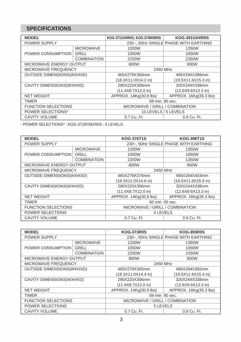
- POWER SELECTIONS* : KOG-371R/391R0S : 5 LEVELS.
MODEL KOG-371G/H/R0S, KOG-374R/5R0S KOG-391G/H/R0SPOWER SUPPLY 230~, 50Hz SINGLE PHASE WITH EARTHING
MICROWAVE 1200W 1350WPOWER CONSUMPTION GRILL 1050W 1050W
COMBINATION 2200W 2350WMICROWAVE ENERGY OUTPUT 800W 900WMICROWAVE FREQUENCY 2450 MHzOUTSIDE DIMENSIONS(WXHXD) 465X279X360mm 495X294X388mm
(18.3X11.0X14.2 in) (19.5X11.6X15.3 in)CAVITY DIMENSIONS(WXHXD) 290X220X306mm 320X244X338mm
(11.4X8.7X12.0 in) (12.6X9.6X13.3 in)NET WEIGHT APPROX. 14Kg(30.9 lbs) APPROX. 16Kg(35.3 lbs)TIMER 59 min. 90 sec.FUNCTION SELECTIONS MICROWAVE / GRILL / COMBINATIONPOWER SELECTIONS* 10 LEVELS / 5 LEVELSCAVITY VOLUME 0.7 Cu. Ft. 0.9 Cu. Ft.
MODEL KOG-376T1S KOG-396T1SPOWER SUPPLY 230~, 50Hz SINGLE PHASE WITH EARTHING
MICROWAVE 1200W 1350WPOWER CONSUMPTION GRILL 1050W 1050W
COMBINATION 2200W 1350WMICROWAVE ENERGY OUTPUT 800W 950WMICROWAVE FREQUENCY 2450 MHzOUTSIDE DIMENSIONS(WXHXD) 465X279X370mm 495X294X403mm
(18.3X11.0X14.6 in) (19.5X11.6X15.9 in)CAVITY DIMENSIONS(WXHXD) 290X220X306mm 320X244X338mm
(11.4X8.7X12.0 in) (12.6X9.6X13.3 in)NET WEIGHT APPROX. 14Kg(30.9 lbs) APPROX. 16Kg(35.3 lbs)TIMER 60 min. 00 sec.FUNCTION SELECTIONS MICROWAVE / GRILL / COMBINATIONPOWER SELECTIONS 4 LEVELSCAVITY VOLUME 0.7 Cu. Ft. 0.9 Cu. Ft.
MODEL KOG-373R0S KOG-393R0SPOWER SUPPLY 230~, 50Hz SINGLE PHASE WITH EARTHING
MICROWAVE 1200W 1350WPOWER CONSUMPTION GRILL 1050W 1050W
COMBINATION 2200W 2350WMICROWAVE ENERGY OUTPUT 800W 950WMICROWAVE FREQUENCY 2450 MHzOUTSIDE DIMENSIONS(WXHXD) 465X279X365mm 495X294X392mm
(18.3X11.0X14.4 in) (19.5X11.6X15.4 in)CAVITY DIMENSIONS(WXHXD) 290X220X306mm 320X244X338mm
(11.4X8.7X12.0 in) (12.6X9.6X13.3 in)NET WEIGHT APPROX. 14Kg(30.9 lbs) APPROX. 16Kg(35.3 lbs)TIMER 59 min. 90 sec.FUNCTION SELECTIONS MICROWAVE / GRILL / COMBINATIONPOWER SELECTIONS 5 LEVELSCAVITY VOLUME 0.7 Cu. Ft. 0.9 Cu. Ft.

4
1. OUTER DIMENSION
1) KOG-371G/H0S, KOG-391G/H0S
465/495
279/
294
360/388
2) KOG-376T1S, KOG-396T1S
3) KOG-373R0S, KOG-393R0S
365/392465/495
279/
294
EXTERNAL VIEW
5
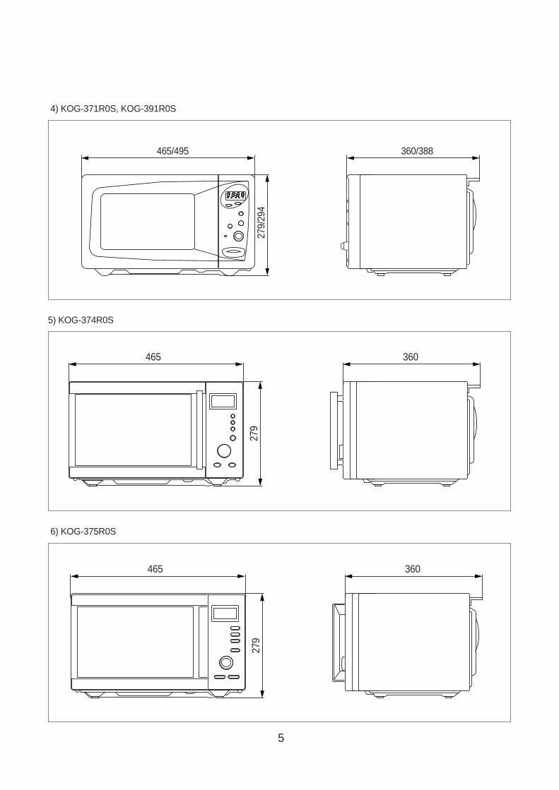
4) KOG-371R0S, KOG-391R0S
465/495
279/
294
360/388
5) KOG-374R0S
465
279
360
6) KOG-375R0S
465
279
360
6
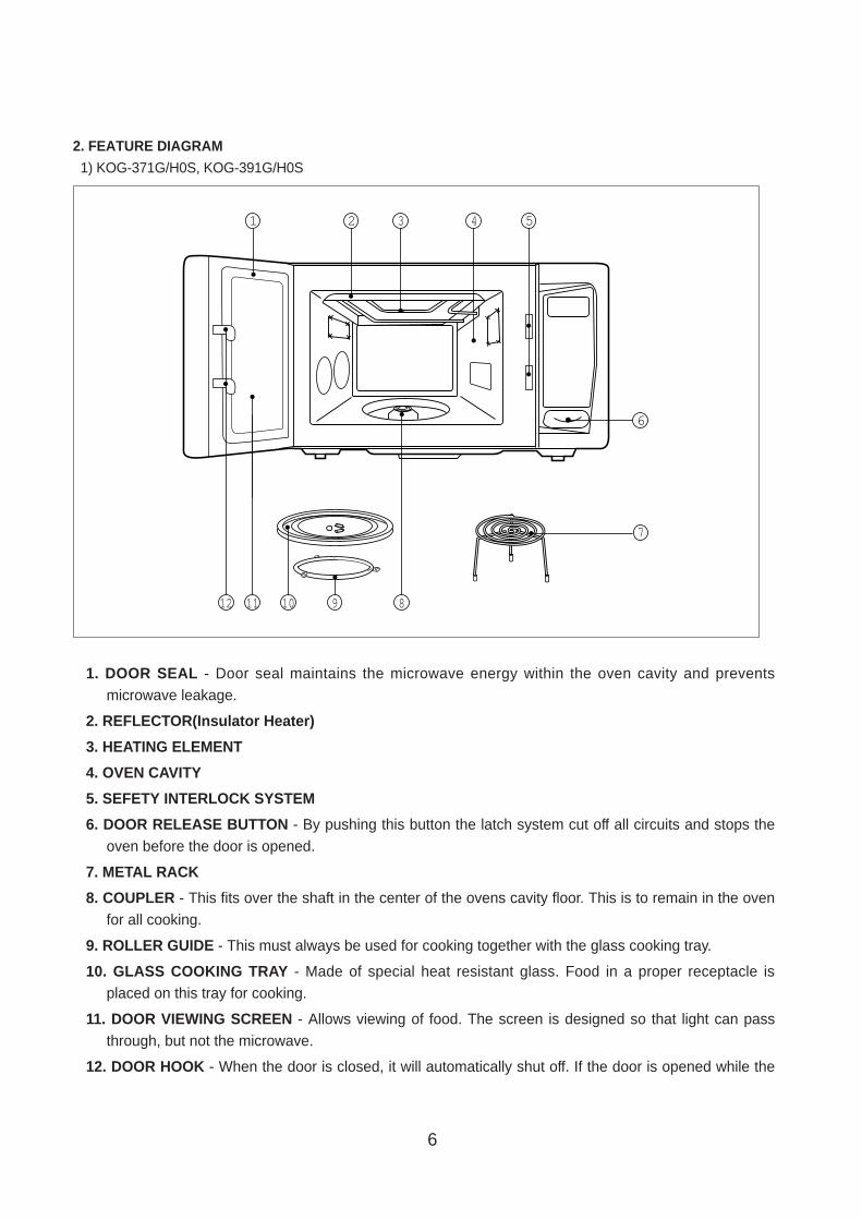
1. DOOR SEAL - Door seal maintains the microwave energy within the oven cavity and preventsmicrowave leakage.
2. REFLECTOR(Insulator Heater)
3. HEATING ELEMENT
4. OVEN CAVITY
5. SEFETY INTERLOCK SYSTEM
6. DOOR RELEASE BUTTON - By pushing this button the latch system cut off all circuits and stops theoven before the door is opened.
7. METAL RACK
8. COUPLER - This fits over the shaft in the center of the ovens cavity floor. This is to remain in the ovenfor all cooking.
9. ROLLER GUIDE - This must always be used for cooking together with the glass cooking tray.
10. GLASS COOKING TRA Y - Made of special heat resistant glass. Food in a proper receptacle isplaced on this tray for cooking.
11. DOOR VIEWING SCREEN - Allows viewing of food. The screen is designed so that light can passthrough, but not the microwave.
12. DOOR HOOK - When the door is closed, it will automatically shut off. If the door is opened while the
2. FEATURE DIAGRAM
1) KOG-371G/H0S, KOG-391G/H0S
1 2 3 4
7
5
6
8101112 9
7
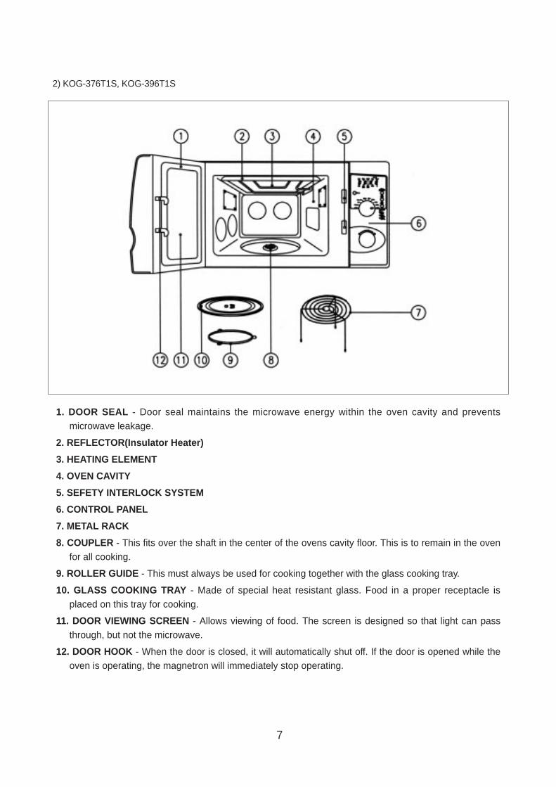
1. DOOR SEAL - Door seal maintains the microwave energy within the oven cavity and preventsmicrowave leakage.
2. REFLECTOR(Insulator Heater)
3. HEATING ELEMENT
4. OVEN CAVITY
5. SEFETY INTERLOCK SYSTEM
6. CONTROL PANEL
7. METAL RACK
8. COUPLER - This fits over the shaft in the center of the ovens cavity floor. This is to remain in the ovenfor all cooking.
9. ROLLER GUIDE - This must always be used for cooking together with the glass cooking tray.
10. GLASS COOKING TRA Y - Made of special heat resistant glass. Food in a proper receptacle isplaced on this tray for cooking.
11. DOOR VIEWING SCREEN - Allows viewing of food. The screen is designed so that light can passthrough, but not the microwave.
12. DOOR HOOK - When the door is closed, it will automatically shut off. If the door is opened while theoven is operating, the magnetron will immediately stop operating.
2) KOG-376T1S, KOG-396T1S

8
1. DOOR SEAL - Door seal maintains the microwave energy within the oven cavity and preventsmicrowave leakage.
2. REFLECTOR(Insulator Heater)
3. HEATING ELEMENT
4. OVEN CAVITY
5. SEFETY INTERLOCK SYSTEM
6. CONTROL PANEL
7. DOOR OPENING BUTTON
8. METAL RACK
9. COUPLER - This fits over the shaft in the center of the ovens cavity floor. This is to remain in the ovenfor all cooking.
10. ROLLER GUIDE - This must always be used for cooking together with the glass cooking tray.
11. GLASS COOKING TRAY - Made of special heat resistant glass. Food in a proper receptacle isplaced on this tray for cooking.
12. DOOR VIEWING SCREEN - Allows viewing of food. The screen is designed so that light can passthrough, but not the microwave.
13. DOOR HOOK - When the door is closed, it will automatically shut off. If the door is opened while theoven is operating, the magnetron will immediately stop operating.
3) KOG-371R0S, KOG-391R0S
1
1112
543
9 8
6
2
10
7
9
1. DOOR SEAL - Door seal maintains the microwave energy within the oven cavity and preventsmicrowave leakage.
2. REFLECTOR(Insulator Heater)
3. HEATING ELEMENT
4. OVEN CAVITY
5. SEFETY INTERLOCK SYSTEM
6. METAL RACK
7. COUPLER - This fits over the shaft in the center of the ovens cavity floor. This is to remain in the ovenfor all cooking.
8. ROLLER GUIDE - This must always be used for cooking together with the glass cooking tray.
9. GLASS COOKING TRAY - Made of special heat resistant glass. Food in a proper receptacle is placedon this tray for cooking.
10. DOOR VIEWING SCREEN - Allows viewing of food. The screen is designed so that light can passthrough, but not the microwave.
11. DOOR HOOK - When the door is closed, it will automatically shut off. If the door is opened while theoven is operating, the magnetron will immediately stop operating.
4) KOG-374R0S
q 1 5
98 740
2 3
6

10
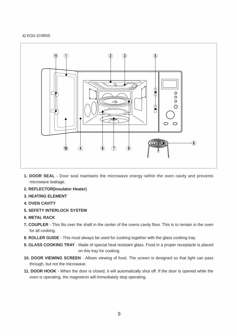
1. DOOR SEAL - Door seal maintains the microwave energy within the oven cavity and preventsmicrowave leakage.
2. REFLECTOR(Insulator Heater)
3. HEATING ELEMENT
4. OVEN CAVITY
5. SEFETY INTERLOCK SYSTEM
6. METAL RACK
7. COUPLER - This fits over the shaft in the center of the ovens cavity floor. This is to remain in the ovenfor all cooking.
8. ROLLER GUIDE - This must always be used for cooking together with the glass cooking tray.
9. GLASS COOKING TRAY - Made of special heat resistant glass. Food in a proper receptacle is placedon this tray for cooking.
10. DOOR VIEWING SCREEN - Allows viewing of food. The screen is designed so that light can passthrough, but not the microwave.
11. DOOR HOOK - When the door is closed, it will automatically shut off. If the door is opened while theoven is operating, the magnetron will immediately stop operating.
5) KOG-375R0S
q 1 5
98 740
2 3
6
11
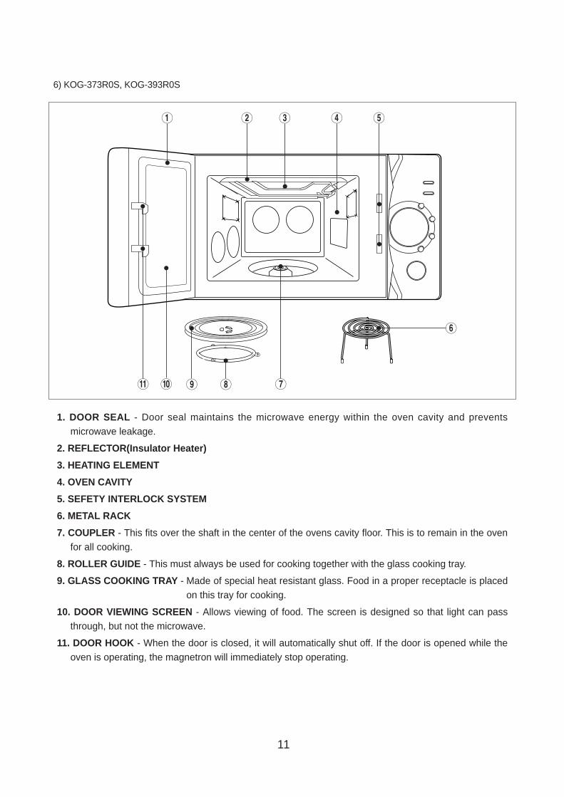
1. DOOR SEAL - Door seal maintains the microwave energy within the oven cavity and preventsmicrowave leakage.
2. REFLECTOR(Insulator Heater)
3. HEATING ELEMENT
4. OVEN CAVITY
5. SEFETY INTERLOCK SYSTEM
6. METAL RACK
7. COUPLER - This fits over the shaft in the center of the ovens cavity floor. This is to remain in the ovenfor all cooking.
8. ROLLER GUIDE - This must always be used for cooking together with the glass cooking tray.
9. GLASS COOKING TRAY - Made of special heat resistant glass. Food in a proper receptacle is placedon this tray for cooking.
10. DOOR VIEWING SCREEN - Allows viewing of food. The screen is designed so that light can passthrough, but not the microwave.
11. DOOR HOOK - When the door is closed, it will automatically shut off. If the door is opened while theoven is operating, the magnetron will immediately stop operating.
6) KOG-373R0S, KOG-393R0S
1 5
790q
2 3 4
6
8
12
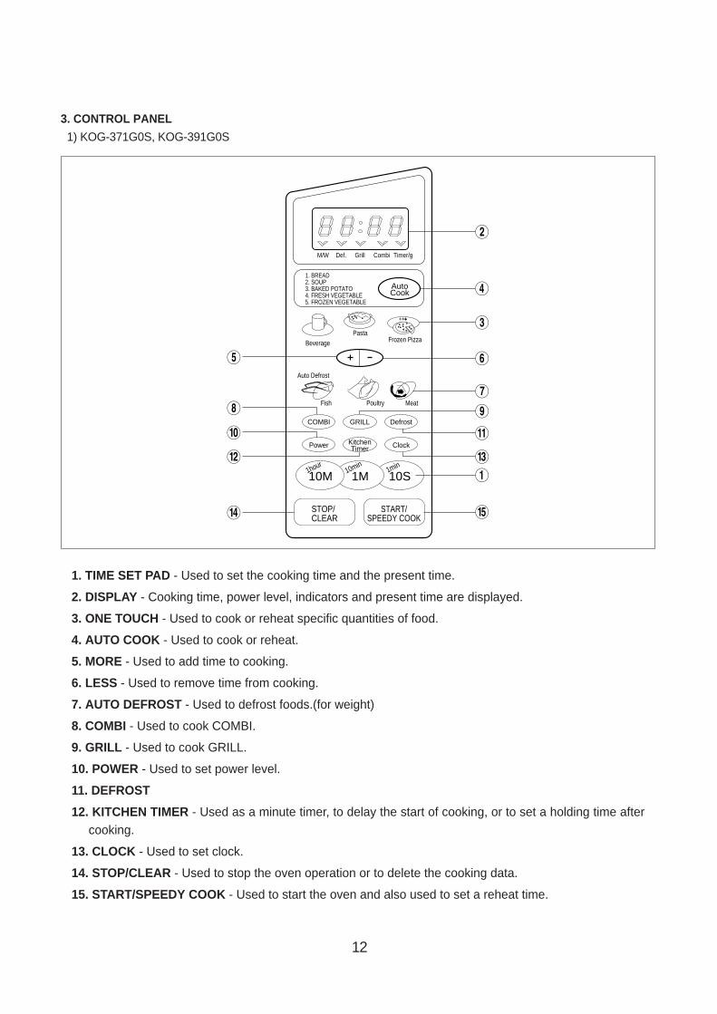
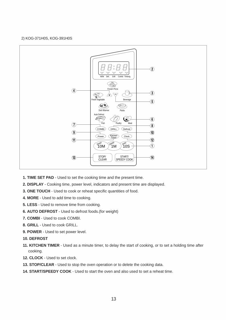
1. TIME SET PAD - Used to set the cooking time and the present time.
2. DISPLAY - Cooking time, power level, indicators and present time are displayed.
3. ONE TOUCH - Used to cook or reheat specific quantities of food.
4. AUTO COOK - Used to cook or reheat.
5. MORE - Used to add time to cooking.
6. LESS - Used to remove time from cooking.
7. AUTO DEFROST - Used to defrost foods.(for weight)
8. COMBI - Used to cook COMBI.
9. GRILL - Used to cook GRILL.
10. POWER - Used to set power level.
11. DEFROST
12. KITCHEN TIMER - Used as a minute timer, to delay the start of cooking, or to set a holding time aftercooking.
13. CLOCK - Used to set clock.
14. STOP/CLEAR - Used to stop the oven operation or to delete the cooking data.
15. START/SPEEDY COOK - Used to start the oven and also used to set a reheat time.
3. CONTROL PANEL
1) KOG-371G0S, KOG-391G0S
M/W Def. Grill Combi Timer/g
Pasta
1. BREAD2. SOUP3. BAKED POTATO4. FRESH VEGETABLE5. FROZEN VEGETABLE
AutoCook
Frozen Pizza
Auto Defrost
Fish Poultry Meat
1min
10S10min
1M1hour
10M
STOP/CLEAR
START/SPEEDY COOK
2
3
4
7
6
9
1
t
q
e
r
w
0
8
5Beverage
GRILL DefrostCOMBI
KitchenTimer ClockPower
13
1. TIME SET PAD - Used to set the cooking time and the present time.
2. DISPLAY - Cooking time, power level, indicators and present time are displayed.
3. ONE TOUCH - Used to cook or reheat specific quantities of food.
4. MORE - Used to add time to cooking.
5. LESS - Used to remove time from cooking.
6. AUTO DEFROST - Used to defrost foods.(for weight)
7. COMBI - Used to cook COMBI.
8. GRILL - Used to cook GRILL.
9. POWER - Used to set power level.
10. DEFROST
11. KITCHEN TIMER - Used as a minute timer, to delay the start of cooking, or to set a holding time aftercooking.
12. CLOCK - Used to set clock.
13. STOP/CLEAR - Used to stop the oven operation or to delete the cooking data.
14. START/SPEEDY COOK - Used to start the oven and also used to set a reheat time.
2) KOG-371H0S, KOG-391H0S
M/W Def. Grill Combi Timer/g
Dish Warmer
Fresh Vegetable
Pasta
Frozen Pizza
Auto Defrost
Fish Poultry Meat
1min
10S10min
1M1hour
10M
STOP/CLEAR
START/SPEEDY COOK
2
3
5
6
8
1
r
0
w
e
q
9
7
4
Beverage
GRILL DefrostCOMBI
KitchenTimer ClockPower
14
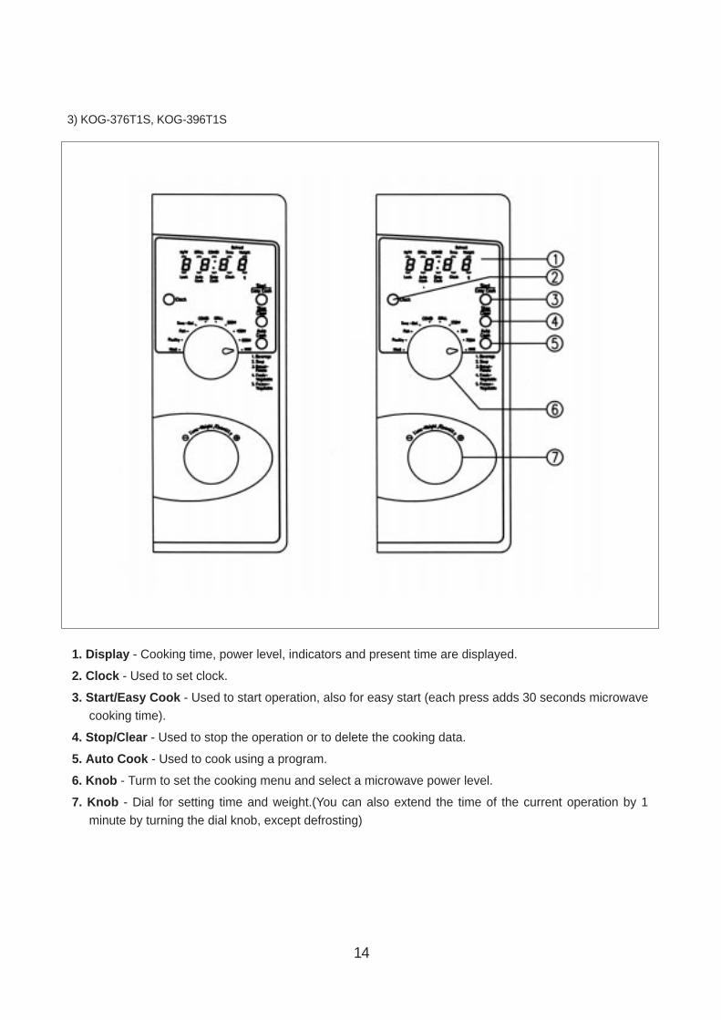
1. Display - Cooking time, power level, indicators and present time are displayed.
2. Clock - Used to set clock.
3. Start/Easy Cook - Used to start operation, also for easy start (each press adds 30 seconds microwavecooking time).
4. Stop/Clear - Used to stop the operation or to delete the cooking data.
5. Auto Cook - Used to cook using a program.
6. Knob - Turm to set the cooking menu and select a microwave power level.
7. Knob - Dial for setting time and weight.(You can also extend the time of the current operation by 1minute by turning the dial knob, except defrosting)
3) KOG-376T1S, KOG-396T1S
15
1. Display - Cooking time, power level, indicators and present time are displayed.
2. Grill/Combi - Used to cook GRILL or COMBI.
3. Power/Def - Used to set power level and DEFROST.
4. Auto cook - Used to cook using a program or to reheat.
5. Start / Easy cook - Used to start the oven operation and also increase the reheat time by 30 seconds.
6. Stop / Clear - Used to stop the oven operation or to erase all entries.
7. Clock - Used to set clock.
8. Dial Knob - Used to set the time and weight.
4) KOG-371R0S, KOG-391R0S
M/W
Grill/CombiPower/Def.
1. Dinner plate2. Soup3. Beverage4. Fresh vegetable
Auto cook
Start/Easy cook
Weight/Time
Stop/Clear
Clock
DEF. Grill Combi g
1
3
6
7
2
4
5
8
16
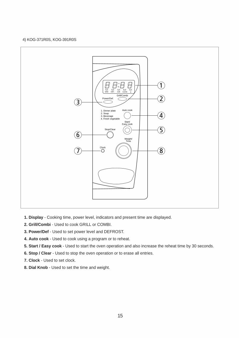
1. Display - Cooking time, power level, indicators and present time are displayed.
2. Grill/Combi - Used to cook GRILL or COMBI.
3. Power/Def - Used to set power level and DEFROST.
4. Auto cook - Used to cook using a program or to reheat.
5. Start / Easy cook - Used to start the oven operation and also increase the reheat time by 30 seconds.
6. Stop / Clear - Used to stop the oven operation or to erase all entries.
7. Clock - Used to set clock.
8. Dial Knob - Used to set the time and weight.
4) KOG-374R0S
Weight/Time
Power/Def
Grill/Combi
Clock
1. Dinner Plate2. Soup3. Beverage4. Fresh Vegetable
Auto Cook
Stop/Clear Start/Easy Cook
1
3
2
7
4
8
6
5
17
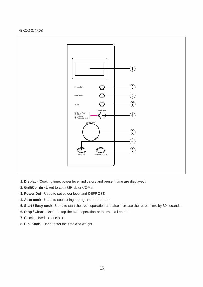
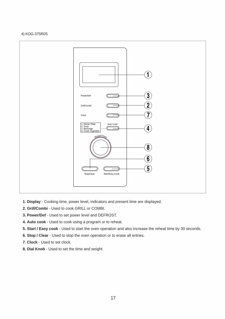
1. Display - Cooking time, power level, indicators and present time are displayed.
2. Grill/Combi - Used to cook GRILL or COMBI.
3. Power/Def - Used to set power level and DEFROST.
4. Auto cook - Used to cook using a program or to reheat.
5. Start / Easy cook - Used to start the oven operation and also increase the reheat time by 30 seconds.
6. Stop / Clear - Used to stop the oven operation or to erase all entries.
7. Clock - Used to set clock.
8. Dial Knob - Used to set the time and weight.
4) KOG-375R0S
Weight/Time
Power/Def
Grill/Combi
Clock
1. Dinner Plate2. Soup3. Beverage4. Fresh Vegetable
Auto Cook
Stop/Clear Start/Easy Cook
1
327
4
8
65
18
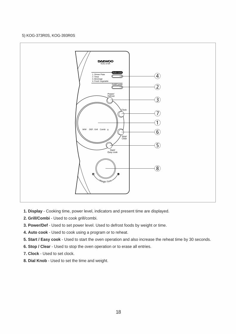
1. Display - Cooking time, power level, indicators and present time are displayed.
2. Grill/Combi - Used to cook grill/combi.
3. Power/Def - Used to set power level. Used to defrost foods by weight or time.
4. Auto cook - Used to cook using a program or to reheat.
5. Start / Easy cook - Used to start the oven operation and also increase the reheat time by 30 seconds.
6. Stop / Clear - Used to stop the oven operation or to erase all entries.
7. Clock - Used to set clock.
8. Dial Knob - Used to set the time and weight.
5) KOG-373R0S, KOG-393R0S
Weigh-Time
M/W DEF. Grill Combi
Power/Defrost
Grill/Combi
1. Dinner Plate2. Soup3. Beverage4. Fresh Vegetable
Auto cook
Clock
Stop/Clear
Start/Easy cook
g
KOG-373R
4
2
3
7
1
6
5
8
19
INSTALLA TION
1. Steady, flat locationThis microwave oven should be set on a steady, flat surface.This microwave oven is designed for counter top use only.
2. Leave space behind and sideAll air vents should be kept a clearance. If all vents are covered during operation, the oven may overheat and,eventually, cause failure.
3. Away from radio and TV setsPoor television reception and radio interference may result if the oven is located close to a TV, radio, antenna orfeeder and so on.Position the oven as far from them as possible.
4. Away from heating appliances and water tapsKeep the oven away from hot air, steam or splash when choosing a place to position it, or the insulation might beadversely affected and breakdowns occur.
5. Power supply• Check your local power source.This microwave oven requires a current of approximately 11 amperes, 230 Volts, 50 Hz.
• Power supply cord is about 1.4 meters long.• The voltage used must be the same as specified on this oven. Using a higher voltage may result in a fire or other
accident causing oven damage. Using low voltage will cause slow cooking. We are not responsible for damageresulting from use of this oven with a voltage of ampere fuse other than those specified.
• This appliance is supplied with cable of special type, which, if damaged, must be reparied with cable of same type.Such a cable can be purchased from DAEWOO and must be installed by Qualified Person.
6. Examine the oven after unpacking for any damage such as:A misaligned door, broken door or a dent in cavity.If any of the above are visible, DO NOT INSTALL, and notify dealer immediately.
7. Do not operate the oven if it is colder than room temperature(This may occur during delivery in cold weather.) Allow the oven to become room temperature before operating.
EARTHING INSTRUCTIONSThis appliance must be earthed. In the event of an electrical short circuit, earthing reduces the risk of the electricshock by providing an escape wire for the electric current. This appliance is equipped with a cord having aearthing wire with a earthing plug. The plug must be plugged into an outlet that is properly installed and earthed.
WARNING : Improper use of the earthing plug can result in a risk of electric shock. Consult a qualified electrician orserviceman if the earthing instructions are not completely understood, or if doubt exists as to whetherthe appliance is properly earthed, and either : If it is necessary to use an extension cord, use only a 3-wire extension cord that has a 3-blade earthing plug, and a 3-slot receptacle that will accept the plug onthe appliance. The marked rating of the extension cord should be equal to or greater than the electricalrating of the appliance, or Do not use an extension cord.
20
1. Connect the main lead to an electrical outlet.2. After placing the food in a suitable container, open the oven door and put it on the glass tray. The glass tray must
always be in place during cooking.3. Close the door securely.4. When the oven door is opened, the light turns off.5. The oven door can be opened at any time during operation by touching the door release button on the control
panel. The oven will automatically shut off. To restart the oven, close the door and then touch START.
6. Each time a pad or a button is touched, a BEEP will sound to acknowledge the touch.7. The oven automatically cook on full power unless set to a lower power level.8. The display will show : 0 when the oven is plugged in.9. Time clock returns to the present time when the cooking time ends.10. When the STOP/CLEAR pad or button is touched during the oven operation, the oven stops cooking and all
information retained. To erase all infomation (except the present time), touch the STOP/CLEAR pad once more. If the oven door isopened during the oven operation, all information is retained.
11. If the START pad is touched and the oven does not operate, check the area between the door and door is closedsecurely. The oven will not start cooking under the door is completely closed or the program has been reset.
12. When using the GRILL or COMBI mode;• Do not open the door so often, the temperature inside the oven derease and the cooking may not be completed
in setting time.• Never touch the oven window and metal interior of the oven when taking food in and out, because the
temperature inside the oven and door is very high.• When using these modes, be careful as the tray will be hot to touch, use oven gloves or pot holders while
handling tray.
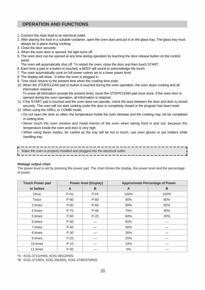
Wattage output chart The power level is set by pressing the power pad. The chart shows the display, the power level and the percentageof power.
*A : KOG-371G/H0S, KOG-391G/H0S*B : KOG-371R0S, KOG-391R0S, KOG-374R/375R0S
Touch Power pad Power level (Display) Approximate Percentage of Power
or button A B A B
Once P-H1 P-HI 100% 100%
Twice P-90 P-80 90% 80%
3 times P-80 P-60 80% 60%
4 times P-70 P-40 70% 40%
5 times P-60 P-20 60% 20%
6 times P-50 — 50% —
7 times P-40 — 40% —
8 times P-30 — 30% —
9 times P-20 — 20% —
10 times P-10 — 10% —
11 times P-00 — 0% —
OPERATION AND FUNCTIONS
Make the oven is properly installed and plugged into the electrical outlet.
21
DISASSEMBLY AND ASSEMBLY
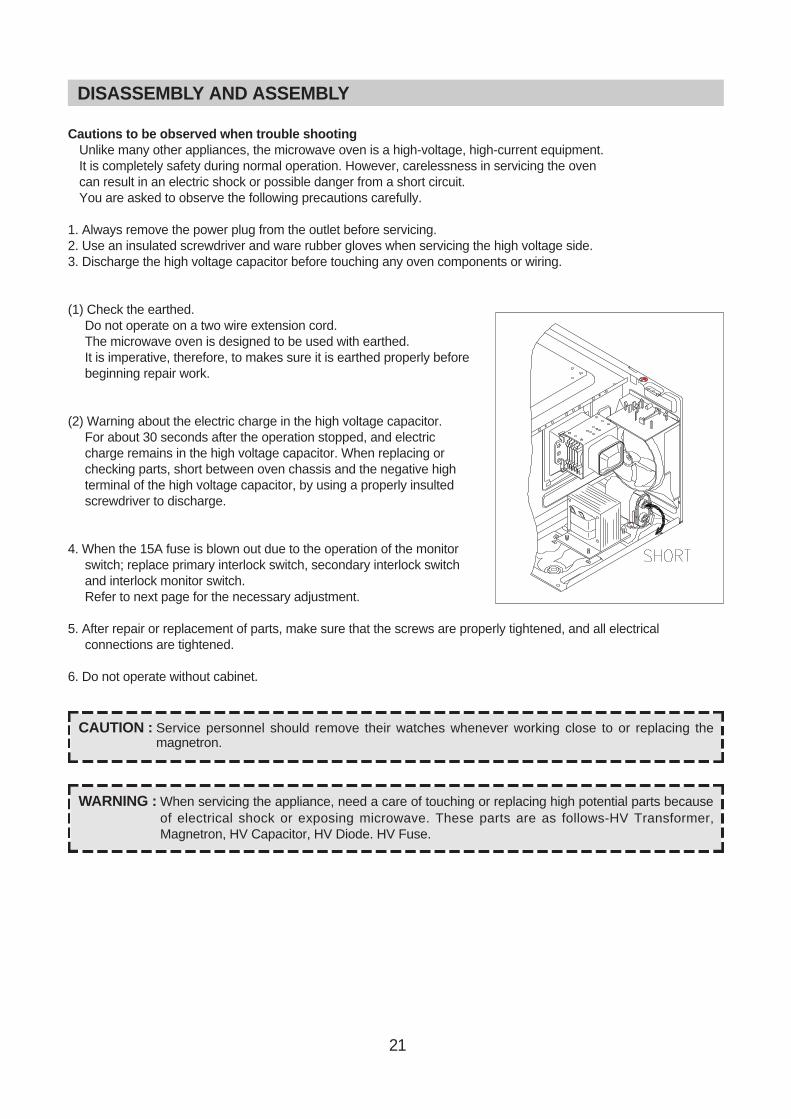
Cautions to be observed when trouble shootingUnlike many other appliances, the microwave oven is a high-voltage, high-current equipment. It is completely safety during normal operation. However, carelessness in servicing the ovencan result in an electric shock or possible danger from a short circuit.You are asked to observe the following precautions carefully.
1. Always remove the power plug from the outlet before servicing.2. Use an insulated screwdriver and ware rubber gloves when servicing the high voltage side.3. Discharge the high voltage capacitor before touching any oven components or wiring.
(1) Check the earthed.Do not operate on a two wire extension cord. The microwave oven is designed to be used with earthed.It is imperative, therefore, to makes sure it is earthed properly beforebeginning repair work.
(2) Warning about the electric charge in the high voltage capacitor.For about 30 seconds after the operation stopped, and electriccharge remains in the high voltage capacitor. When replacing orchecking parts, short between oven chassis and the negative highterminal of the high voltage capacitor, by using a properly insultedscrewdriver to discharge.
4. When the 15A fuse is blown out due to the operation of the monitorswitch; replace primary interlock switch, secondary interlock switchand interlock monitor switch.Refer to next page for the necessary adjustment.
5. After repair or replacement of parts, make sure that the screws are properly tightened, and all electricalconnections are tightened.
6. Do not operate without cabinet.
CAUTION : Service personnel should remove their watches whenever working close to or replacing themagnetron.
WARNING : When servicing the appliance, need a care of touching or replacing high potential parts becauseof electrical shock or exposing microwave. These parts are as follows-HV Transformer,Magnetron, HV Capacitor, HV Diode. HV Fuse.
22
DISASSEMBLY AND ASSEMBLY
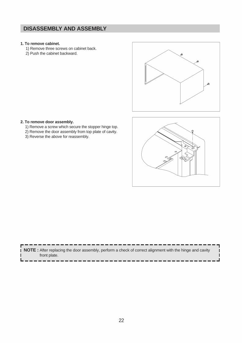
1. To remove cabinet.1) Remove three screws on cabinet back.2) Push the cabinet backward.
2. To remove door assembly.1) Remove a screw which secure the stopper hinge top.2) Remove the door assembly from top plate of cavity.3) Reverse the above for reassembly.
NOTE : After replacing the door assembly, perform a check of correct alignment with the hinge and cavityfront plate.
23
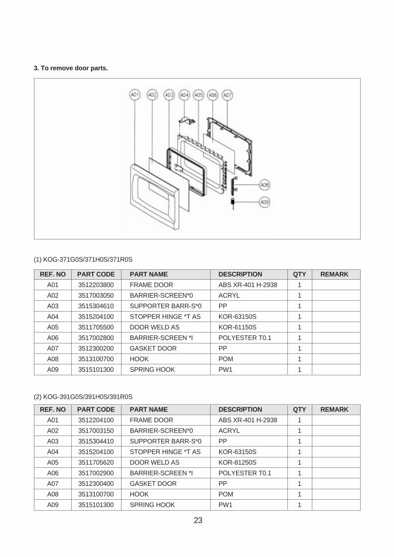
3. To remove door parts.
(1) KOG-371G0S/371H0S/371R0S
(2) KOG-391G0S/391H0S/391R0S
REF. NO PART CODE PART NAME DESCRIPTION QTY REMARK
A01 3512204100 FRAME DOOR ABS XR-401 H-2938 1
A02 3517003150 BARRIER-SCREEN*0 ACRYL 1
A03 3515304410 SUPPORTER BARR-S*0 PP 1
A04 3515204100 STOPPER HINGE *T AS KOR-63150S 1
A05 3511705620 DOOR WELD AS KOR-81250S 1
A06 3517002900 BARRIER-SCREEN *I POLYESTER T0.1 1
A07 3512300400 GASKET DOOR PP 1
A08 3513100700 HOOK POM 1
A09 3515101300 SPRING HOOK PW1 1
REF. NO PART CODE PART NAME DESCRIPTION QTY REMARK
A01 3512203800 FRAME DOOR ABS XR-401 H-2938 1
A02 3517003050 BARRIER-SCREEN*0 ACRYL 1
A03 3515304610 SUPPORTER BARR-S*0 PP 1
A04 3515204100 STOPPER HINGE *T AS KOR-63150S 1
A05 3511705500 DOOR WELD AS KOR-61150S 1
A06 3517002800 BARRIER-SCREEN *I POLYESTER T0.1 1
A07 3512300200 GASKET DOOR PP 1
A08 3513100700 HOOK POM 1
A09 3515101300 SPRING HOOK PW1 1

24
1) Remove the gasket door from door plate.2) Remove the barrier screen inner from door plate.3) Remove the door frame from door plate.4) Remove the stopper hinge top from door plate.5) Remove the spring and the hook.6) Remove the supporter barrier screen outer from door frame.7) Remove the barrier screen outer from door frame.8) Remove the above steps for reassembly.
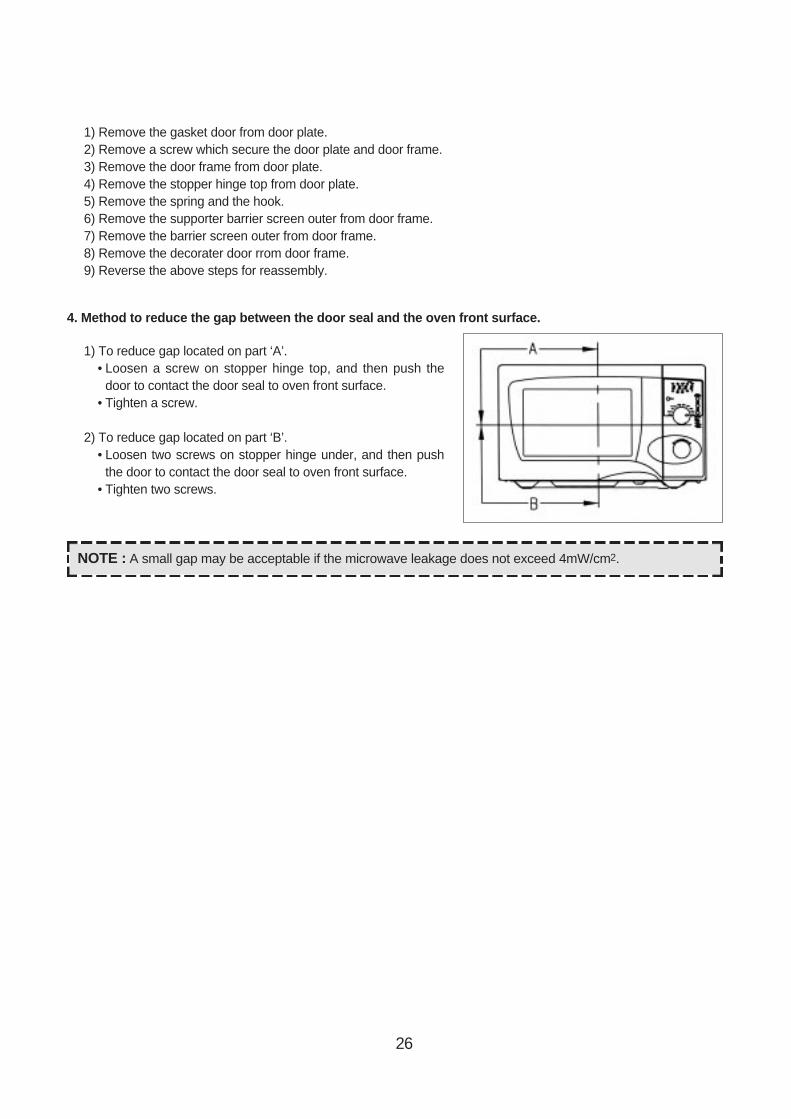
4. Method to reduce the gap between the door seal and the oven front surface.
1) To reduce gap located on part ‘A’.• Loosen a screw on stopper hinge top, and then push the
door to contact the door seal to oven front surface.• Tighten a screw.
2) To reduce gap located on part ‘B’.• Loosen two screws on stopper hinge under, and then push
the door to contact the door seal to oven front surface.• Tighten two screws.
A
B
NOTE : A small gap may be acceptable if the microwave leakage does not exceed 4mW/cm2.
25
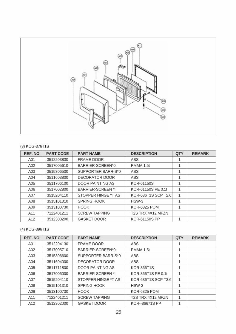
(3) KOG-376T1S
(4) KOG-396T1S
REF. NO PART CODE PART NAME DESCRIPTION QTY REMARK
A01 3512203830 FRAME DOOR ABS 1
A02 3517005610 BARRIER-SCREEN*0 PMMA 1.5t 1
A03 3515306500 SUPPORTER BARR-S*0 ABS 1
A04 3511603800 DECORATOR DOOR ABS 1
A05 3511706100 DOOR PAINTING AS KOR-61150S 1
A06 3517002800 BARRIER-SCREEN *I KOR-61150S PE 0.1t 1
A07 3515204110 STOPPER HINGE *T AS KOR-636T1S SCP T2.6 1
A08 3515101310 SPRING HOOK HSW-3 1
A09 3513100730 HOOK KOR-6325 POM 1
A11 7122401211 SCREW TAPPING T2S TRX 4X12 MFZN
A12 3512300200 GASKET DOOR KOR-61150S PP 1
REF. NO PART CODE PART NAME DESCRIPTION QTY REMARK
A01 3512204130 FRAME DOOR ABS 1
A02 3517005710 BARRIER-SCREEN*0 PMMA 1.5t 1
A03 3515306600 SUPPORTER BARR-S*0 ABS 1
A04 3511604000 DECORATOR DOOR ABS 1
A05 3511711800 DOOR PAINTING AS KOR-866T1S 1
A06 3517006000 BARRIER-SCREEN *I KOR-866T1S PE 0.1t 1
A07 3515204110 STOPPER HINGE *T AS KOR-636T1S SCP T2.6 1
A08 3515101310 SPRING HOOK HSW-3 1
A09 3513100730 HOOK KOR-6325 POM 1
A11 7122401211 SCREW TAPPING T2S TRX 4X12 MFZN 1
A12 3512302000 GASKET DOOR KOR--86671S PP 1
26
1) Remove the gasket door from door plate.2) Remove a screw which secure the door plate and door frame.3) Remove the door frame from door plate.4) Remove the stopper hinge top from door plate.5) Remove the spring and the hook.6) Remove the supporter barrier screen outer from door frame.7) Remove the barrier screen outer from door frame.8) Remove the decorater door rrom door frame.9) Reverse the above steps for reassembly.
4. Method to reduce the gap between the door seal and the oven front surface.
1) To reduce gap located on part ‘A’.• Loosen a screw on stopper hinge top, and then push the
door to contact the door seal to oven front surface.• Tighten a screw.
2) To reduce gap located on part ‘B’.• Loosen two screws on stopper hinge under, and then push
the door to contact the door seal to oven front surface.• Tighten two screws.
NOTE : A small gap may be acceptable if the microwave leakage does not exceed 4mW/cm2.

27
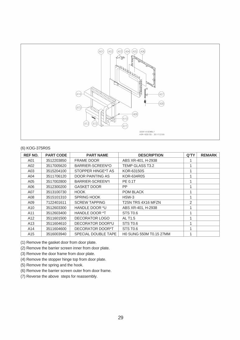
REF NO. PART CODE PART NAME DESCRIPTION Q’TY REMARK
A01 3512203850 FRAME DOOR ABS XR-401, H-2938 1
A02 3517005620 BARRIER-SCREEN*O TEMP GLASS T3.2 1
A03 3515204100 STOPPER HINGE*T AS KOR-63150S 1
A04 3511706120 DOOR PAINTING AS KOR-634R0S 1
A05 3517002800 BARRIER-SCREEN*I PE 0.1T 1
A06 3512300200 GASKET DOOR PP 1
A07 3513100730 HOOK POM BLACK 1
A08 3515101310 SPRING HOOK HSW-3 1
A09 7001503311 SCREW MACHINE PAN 5X33 MFZN 2
A10 3512603210 HANDLE DOOR STEEL NI + CR 1
A11 3511601500 DECORATOR LOGO AL T1.5 1
A12 3511604610 DECORATOR DOOR*U STS T0.6 1
A13 3511604600 DECORATOR DOOR*T STS T0.6 1
A14 3516003940 SPECIAL DOUBLE TAPE H0 SUNG 550M 1
(5) KOG-374R0S
28
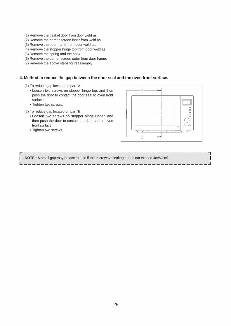
4. Method to reduce the gap between the door seal and the oven front surface.
(1) To reduce gap located on part ‘A’• Loosen two screws on stopper hinge top, and then
push the door to contact the door seal to oven frontsurface.
• Tighten two screws.
(2) To reduce gap located on part ‘B’• Loosen two screws on stopper hinge under, and
then push the door to contact the door seal to ovenfront surface.
• Tighten two screws.
(1) Remove the gasket door from door weld as.(2) Remove the barrier screen inner from weld as.(3) Remove the door frame from door weld as.(4) Remove the stopper hinge top from door weld as.(5) Remove the spring and the hook.(6) Remove the barrier screen outer from door frame.(7) Reverse the above steps for reassembly.
NOTE : A small gap may be acceptable if the microwave leakage does not exceed 4mW/cm2.
29
REF NO. PART CODE PART NAME DESCRIPTION Q’TY REMARKA01 3512203850 FRAME DOOR ABS XR-401, H-2938 1A02 3517005620 BARRIER-SCREEN*O TEMP GLASS T3.2 1A03 3515204100 STOPPER HINGE*T AS KOR-63150S 1A04 3511706120 DOOR PAINTING AS KOR-634R0S 1A05 3517002800 BARRIER-SCREEN*I PE 0.1T 1A06 3512300200 GASKET DOOR PP 1A07 3513100730 HOOK POM BLACK 1A08 3515101310 SPRING HOOK HSW-3 1A09 7122401611 SCREW TAPPING T2SN TRS 4X16 MFZN 2A10 3512603300 HANDLE DOOR *U ABS XR-401, H-2938 1A11 3512603400 HANDLE DOOR *T STS T0.6 1A12 3511601500 DECORATOR LOGO AL T1.5 1A13 3511604610 DECORATOR DOOR*U STS T0.6 1A14 3511604600 DECORATOR DOOR*T STS T0.6 1A15 3516003940 SPECIAL DOUBLE TAPE H0 SUNG 550M T0.15 27MM 1
(6) KOG-375R0S
(1) Remove the gasket door from door plate.(2) Remove the barrier screen inner from door plate.(3) Remove the door frame from door plate.(4) Remove the stopper hinge top from door plate.(5) Remove the spring and the hook.(6) Remove the barrier screen outer from door frame.(7) Reverse the above steps for reassembly.
30
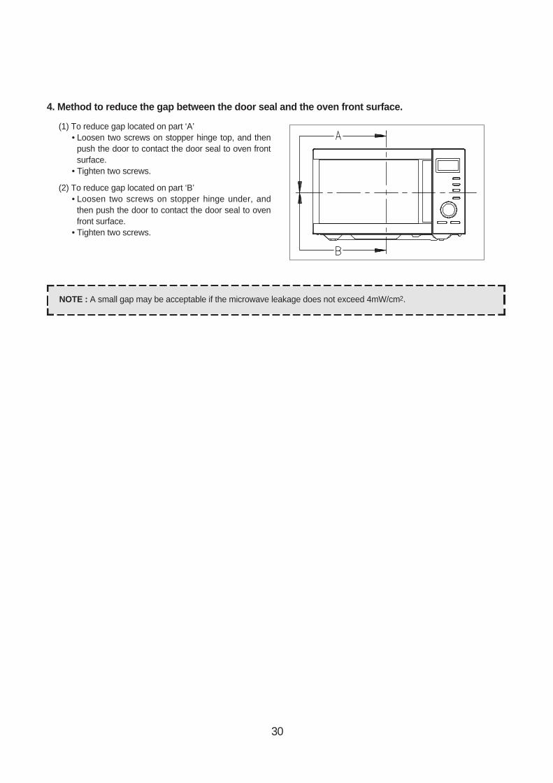
4. Method to reduce the gap between the door seal and the oven front surface.
(1) To reduce gap located on part ‘A’• Loosen two screws on stopper hinge top, and then
push the door to contact the door seal to oven frontsurface.
• Tighten two screws.
(2) To reduce gap located on part ‘B’• Loosen two screws on stopper hinge under, and
then push the door to contact the door seal to ovenfront surface.
• Tighten two screws.
NOTE : A small gap may be acceptable if the microwave leakage does not exceed 4mW/cm2.
31
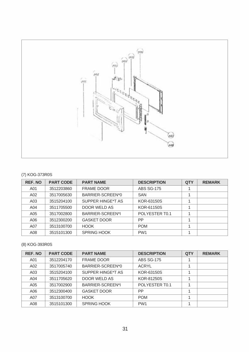
(7) KOG-373R0S
(8) KOG-393R0S
REF. NO PART CODE PART NAME DESCRIPTION QTY REMARK
A01 3512203860 FRAME DOOR ABS SG-175 1
A02 3517005630 BARRIER-SCREEN*0 SAN 1
A03 3515204100 SUPPER HINGE*T AS KOR-63150S 1
A04 3511705500 DOOR WELD AS KOR-61150S 1
A05 3517002800 BARRIER-SCREEN*I POLYESTER T0.1 1
A06 3512300200 GASKET DOOR PP 1
A07 3513100700 HOOK POM 1
A08 3515101300 SPRING HOOK PW1 1
REF. NO PART CODE PART NAME DESCRIPTION QTY REMARK
A01 3512204170 FRAME DOOR ABS SG-175 1
A02 3517005740 BARRIER-SCREEN*0 ACRYL 1
A03 3515204100 SUPPER HINGE*T AS KOR-63150S 1
A04 3511705620 DOOR WELD AS KOR-81250S 1
A05 3517002900 BARRIER-SCREEN*I POLYESTER T0.1 1
A06 3512300400 GASKET DOOR PP 1
A07 3513100700 HOOK POM 1
A08 3515101300 SPRING HOOK PW1 1
32
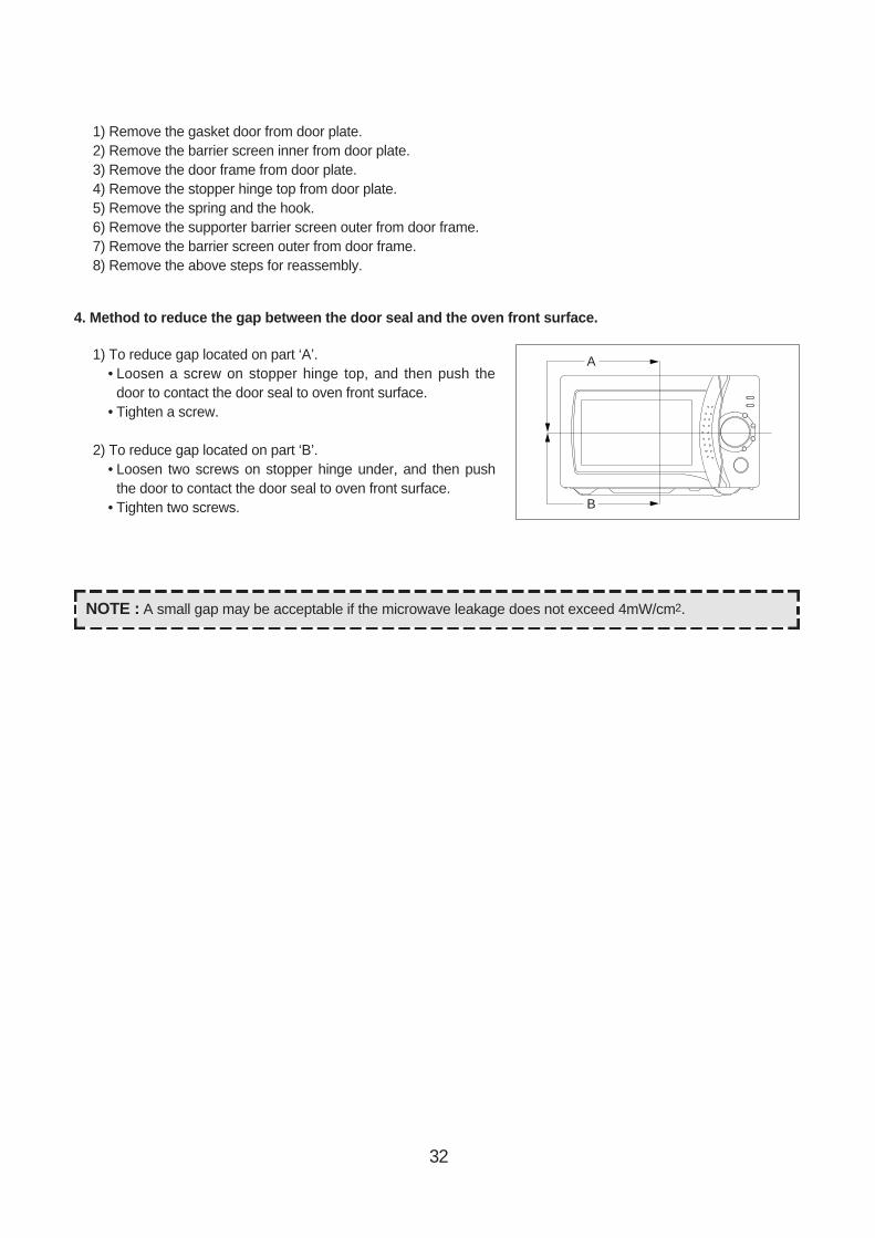
1) Remove the gasket door from door plate.2) Remove the barrier screen inner from door plate.3) Remove the door frame from door plate.4) Remove the stopper hinge top from door plate.5) Remove the spring and the hook.6) Remove the supporter barrier screen outer from door frame.7) Remove the barrier screen outer from door frame.8) Remove the above steps for reassembly.
4. Method to reduce the gap between the door seal and the oven front surface.
1) To reduce gap located on part ‘A’.• Loosen a screw on stopper hinge top, and then push the
door to contact the door seal to oven front surface.• Tighten a screw.
2) To reduce gap located on part ‘B’.• Loosen two screws on stopper hinge under, and then push
the door to contact the door seal to oven front surface.• Tighten two screws.
A
B
NOTE : A small gap may be acceptable if the microwave leakage does not exceed 4mW/cm2.
33
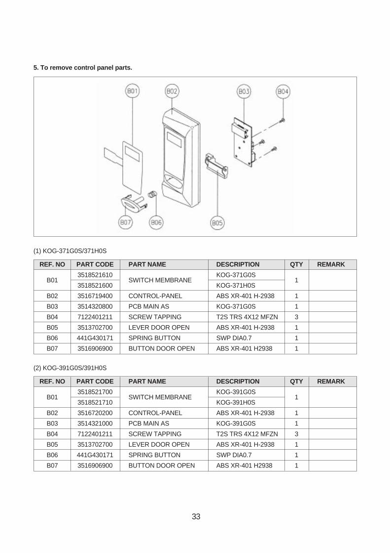
(1) KOG-371G0S/371H0S
REF. NO PART CODE PART NAME DESCRIPTION QTY REMARK
B013518521610
SWITCH MEMBRANEKOG-371G0S
13518521600 KOG-371H0S
B02 3516719400 CONTROL-PANEL ABS XR-401 H-2938 1
B03 3514320800 PCB MAIN AS KOG-371G0S 1
B04 7122401211 SCREW TAPPING T2S TRS 4X12 MFZN 3
B05 3513702700 LEVER DOOR OPEN ABS XR-401 H-2938 1
B06 441G430171 SPRING BUTTON SWP DIA0.7 1
B07 3516906900 BUTTON DOOR OPEN ABS XR-401 H2938 1
(2) KOG-391G0S/391H0S
REF. NO PART CODE PART NAME DESCRIPTION QTY REMARK
B013518521700
SWITCH MEMBRANEKOG-391G0S
13518521710 KOG-391H0S
B02 3516720200 CONTROL-PANEL ABS XR-401 H-2938 1
B03 3514321000 PCB MAIN AS KOG-391G0S 1
B04 7122401211 SCREW TAPPING T2S TRS 4X12 MFZN 3
B05 3513702700 LEVER DOOR OPEN ABS XR-401 H-2938 1
B06 441G430171 SPRING BUTTON SWP DIA0.7 1
B07 3516906900 BUTTON DOOR OPEN ABS XR-401 H2938 1
5. To remove control panel parts.
3434
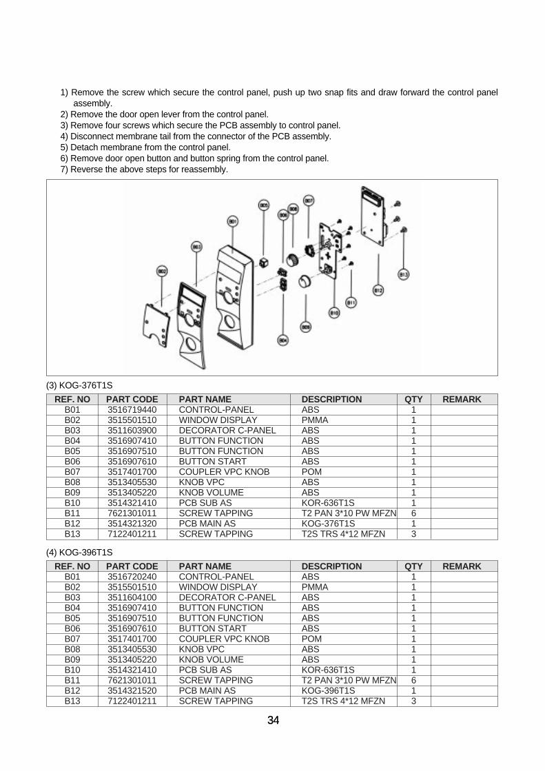
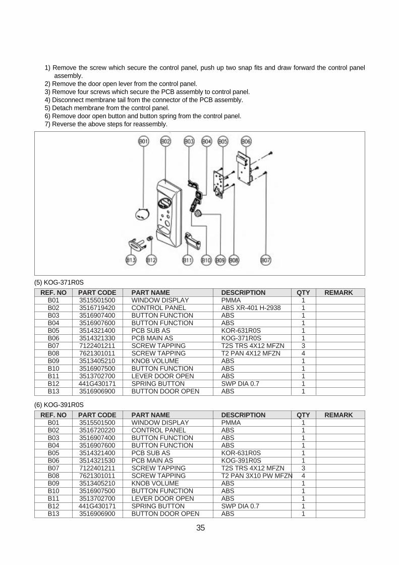
1) Remove the screw which secure the control panel, push up two snap fits and draw forward the control panelassembly.
2) Remove the door open lever from the control panel.3) Remove four screws which secure the PCB assembly to control panel.4) Disconnect membrane tail from the connector of the PCB assembly.5) Detach membrane from the control panel.6) Remove door open button and button spring from the control panel.7) Reverse the above steps for reassembly.
(3) KOG-376T1S
REF. NO PART CODE PART NAME DESCRIPTION QTY REMARKB01 3516719440 CONTROL-PANEL ABS 1B02 3515501510 WINDOW DISPLAY PMMA 1B03 3511603900 DECORATOR C-PANEL ABS 1B04 3516907410 BUTTON FUNCTION ABS 1B05 3516907510 BUTTON FUNCTION ABS 1B06 3516907610 BUTTON START ABS 1B07 3517401700 COUPLER VPC KNOB POM 1B08 3513405530 KNOB VPC ABS 1B09 3513405220 KNOB VOLUME ABS 1B10 3514321410 PCB SUB AS KOR-636T1S 1B11 7621301011 SCREW TAPPING T2 PAN 3*10 PW MFZN 6B12 3514321320 PCB MAIN AS KOG-376T1S 1B13 7122401211 SCREW TAPPING T2S TRS 4*12 MFZN 3
(4) KOG-396T1S
REF. NO PART CODE PART NAME DESCRIPTION QTY REMARKB01 3516720240 CONTROL-PANEL ABS 1B02 3515501510 WINDOW DISPLAY PMMA 1B03 3511604100 DECORATOR C-PANEL ABS 1B04 3516907410 BUTTON FUNCTION ABS 1B05 3516907510 BUTTON FUNCTION ABS 1B06 3516907610 BUTTON START ABS 1B07 3517401700 COUPLER VPC KNOB POM 1B08 3513405530 KNOB VPC ABS 1B09 3513405220 KNOB VOLUME ABS 1B10 3514321410 PCB SUB AS KOR-636T1S 1B11 7621301011 SCREW TAPPING T2 PAN 3*10 PW MFZN 6B12 3514321520 PCB MAIN AS KOG-396T1S 1B13 7122401211 SCREW TAPPING T2S TRS 4*12 MFZN 3
35
1) Remove the screw which secure the control panel, push up two snap fits and draw forward the control panelassembly.
2) Remove the door open lever from the control panel.3) Remove four screws which secure the PCB assembly to control panel.4) Disconnect membrane tail from the connector of the PCB assembly.5) Detach membrane from the control panel.6) Remove door open button and button spring from the control panel.7) Reverse the above steps for reassembly.
(5) KOG-371R0S
REF. NO PART CODE PART NAME DESCRIPTION QTY REMARKB01 3515501500 WINDOW DISPLAY PMMA 1B02 3516719420 CONTROL PANEL ABS XR-401 H-2938 1B03 3516907400 BUTTON FUNCTION ABS 1B04 3516907600 BUTTON FUNCTION ABS 1B05 3514321400 PCB SUB AS KOR-631R0S 1B06 3514321330 PCB MAIN AS KOG-371R0S 1B07 7122401211 SCREW TAPPING T2S TRS 4X12 MFZN 3B08 7621301011 SCREW TAPPING T2 PAN 4X12 MFZN 4B09 3513405210 KNOB VOLUME ABS 1B10 3516907500 BUTTON FUNCTION ABS 1B11 3513702700 LEVER DOOR OPEN ABS 1B12 441G430171 SPRING BUTTON SWP DIA 0.7 1B13 3516906900 BUTTON DOOR OPEN ABS 1
(6) KOG-391R0S
REF. NO PART CODE PART NAME DESCRIPTION QTY REMARKB01 3515501500 WINDOW DISPLAY PMMA 1B02 3516720220 CONTROL PANEL ABS 1B03 3516907400 BUTTON FUNCTION ABS 1B04 3516907600 BUTTON FUNCTION ABS 1B05 3514321400 PCB SUB AS KOR-631R0S 1B06 3514321530 PCB MAIN AS KOG-391R0S 1B07 7122401211 SCREW TAPPING T2S TRS 4X12 MFZN 3B08 7621301011 SCREW TAPPING T2 PAN 3X10 PW MFZN 4B09 3513405210 KNOB VOLUME ABS 1B10 3516907500 BUTTON FUNCTION ABS 1B11 3513702700 LEVER DOOR OPEN ABS 1B12 441G430171 SPRING BUTTON SWP DIA 0.7 1B13 3516906900 BUTTON DOOR OPEN ABS 1
36
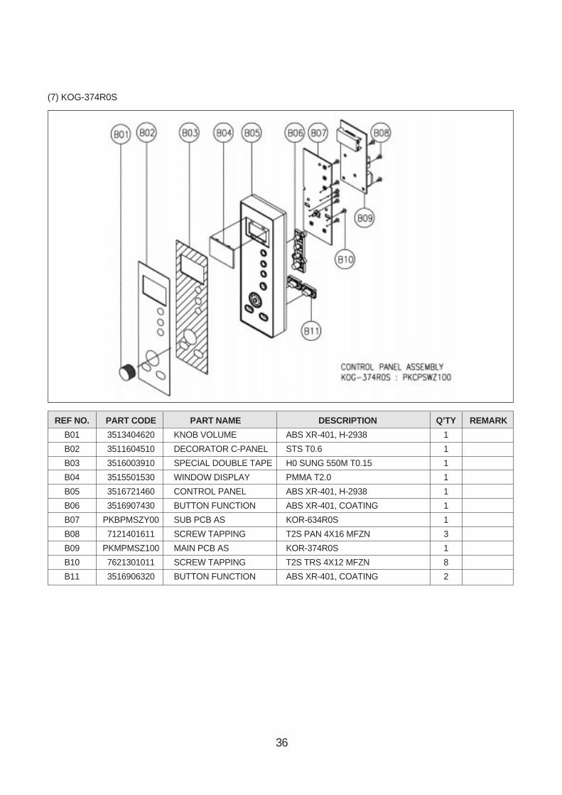
REF NO. PART CODE PART NAME DESCRIPTION Q’TY REMARK
B01 3513404620 KNOB VOLUME ABS XR-401, H-2938 1
B02 3511604510 DECORATOR C-PANEL STS T0.6 1
B03 3516003910 SPECIAL DOUBLE TAPE H0 SUNG 550M T0.15 1
B04 3515501530 WINDOW DISPLAY PMMA T2.0 1
B05 3516721460 CONTROL PANEL ABS XR-401, H-2938 1
B06 3516907430 BUTTON FUNCTION ABS XR-401, COATING 1
B07 PKBPMSZY00 SUB PCB AS KOR-634R0S 1
B08 7121401611 SCREW TAPPING T2S PAN 4X16 MFZN 3
B09 PKMPMSZ100 MAIN PCB AS KOR-374R0S 1
B10 7621301011 SCREW TAPPING T2S TRS 4X12 MFZN 8
B11 3516906320 BUTTON FUNCTION ABS XR-401, COATING 2
(7) KOG-374R0S

37
REF NO. PART CODE PART NAME DESCRIPTION Q’TY REMARK
B01 3513403800 KNOB VOLUME ABS XR-401, H-2938 1
B02 3511604530 DECORATOR C-PANEL STS T0.6 1
B03 3516003960 SPECIAL DOUBLE TAPE H0 SUNG 550M T0.15 1
B04 3515501530 WINDOW DISPLAY PMMA T2.0 1
B05 3516723700 CONTROL PANEL ABS XR-401, H-2938 1
B06 3516907440 BUTTON FUNCTION ABS XR-401 1
B07 PKBPMSZY00 SUB PCB AS KOR-634R0S 1
B08 7121401611 SCREW TAPPING T2S PAN 4X16 MFZN 3
B09 PKMPMSZ100 MAIN PCB AS KOR-374R0S 1
B10 7621301011 SCREW TAPPING T2S TRS 4X12 MFZN 8
B11 3516904600 BUTTON FUNCTION ABS XR-401 2
(8) KOG-375R0S

38
(9) KOG-373R0S
(10) KOG-393R0S
REF. NO PART CODE PART NAME DESCRIPTION QTY REMARKB01 3515501540 WINDOW DISPLAY PMMA 1
B02 3516723730 CONTROL PANEL ABS SG-175 1
B03 3516907530 BUTTON FUCTION *A ABS SG-175 1
B04 3516907540 BUTTON FUCTION *B ABS SG-175 1
B05 3513405240 KNOB VOLUME ABS 1
B06 PKBPMSZ300 PCB SUB AS KOG-373R0S 1
B07 7621301011 SCREW TAPPING T2 PAN 2X10 PW MFZN 4
B08 PKMPMSZ600 PCB MAIN AS KOG-373R0S 1
B09 7122401211 SCREW TAPPING T2S TRS 4X12 MFZN 3
REF. NO PART CODE PART NAME DESCRIPTION QTY REMARKB01 3515501540 WINDOW DISPLAY PMMA 1
B02 3516723730 CONTROL PANEL ABS SG-175 1
B03 3516907530 BUTTON FUCTION *A ABS SG-175 1
B04 3516907540 BUTTON FUCTION *B ABS SG-175 1
B05 3513405240 KNOB VOLUME ABS SG-175 1
B06 PKBPMSZ300 PCB SUB AS KOG-373R0S 1
B07 7621301011 SCREW TAPPING T2 PAN 2X10 PW MFZN 4
B08 PKMPMST500 PCB MAIN AS KOG-393R0S 1
B09 7122401211 SCREW TAPPING T2S TRS 4X12 MFZN 3

39
1) Remove the screw which secure the control panel, push up two snap fits and draw forward the control panelassembly.
2) Remove the door open lever from the control panel.3) Remove four screws which secure the PCB assembly to control panel.4) Disconnect membrane tail from the connector of the PCB assembly.5) Detach membrane from the control panel.6) Remove door open button and button spring from the control panel.7) Reverse the above steps for reassembly.
6. To remove high voltage capacitor.
1) Remove a screw which secure the grounding ringterminal of the H.V.diode and the capacitor holder.
2) Remove the H.V.diode from the capacitor holder.3) Reverse the above steps for reassembly.
• High voltage circuit wiring
7. To remove magnetron.
1) Remove a screw which secure the magnetron.2) Remove the magnetron.3) Reverse the above steps for reassembly.
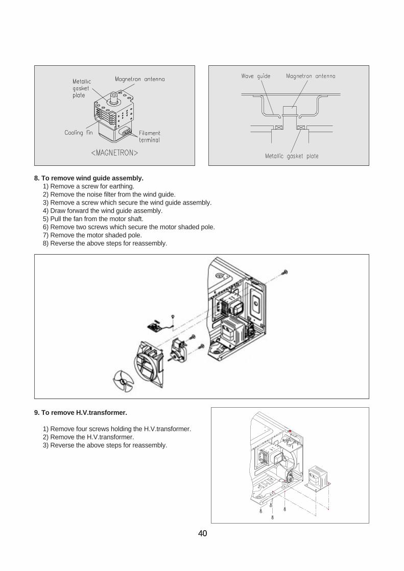
NOTE : Never install the magnetron without the metallic gasket plate which is packed with each magnetron toprevent microwave leakage. Whenever repair work is carried out on magnetron, check the microwaveleakage. It shall not exceed 4mW/cm2 for a fully assembled oven with door normally closed.
4040
8. To remove wind guide assembly.1) Remove a screw for earthing.2) Remove the noise filter from the wind guide.3) Remove a screw which secure the wind guide assembly.4) Draw forward the wind guide assembly.5) Pull the fan from the motor shaft.6) Remove two screws which secure the motor shaded pole.7) Remove the motor shaded pole.8) Reverse the above steps for reassembly.
9. To remove H.V.transformer.
1) Remove four screws holding the H.V.transformer.2) Remove the H.V.transformer.3) Reverse the above steps for reassembly.
41
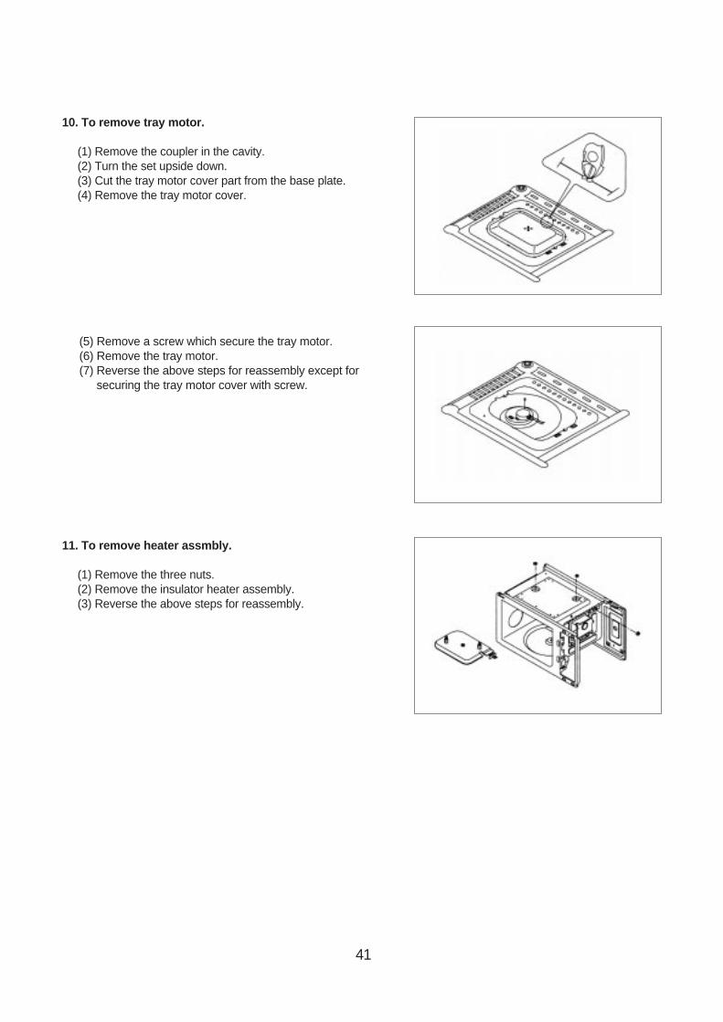
10. To remove tray motor.
(1) Remove the coupler in the cavity.(2) Turn the set upside down.(3) Cut the tray motor cover part from the base plate.(4) Remove the tray motor cover.
(5) Remove a screw which secure the tray motor.(6) Remove the tray motor.(7) Reverse the above steps for reassembly except for
securing the tray motor cover with screw.
11. To remove heater assmbly.
(1) Remove the three nuts.(2) Remove the insulator heater assembly.(3) Reverse the above steps for reassembly.

42
REF. NO PART CODE PART NAME DESCRIPTION QTY REMARK
C01 7392500008 NUT HEX 6N-2-5 SUS 1
C02 3515000600 SPACER INSULATOR *I C377BD 2
C03 3513301100 INSULATOR HEATER SPP T0.8 1
C04 3512803400 HEATER 230V 1000W 1R67994001 1
C05 7002500613 SCREW MACHINE TRS 5X6 MFCR 1
C06 7002400413 SCREW MACHINE TRS 4X4 MFCR 2
12. To remove heater parts.

43
INTERLOCK MECHANISM AND ADJUSTMENT
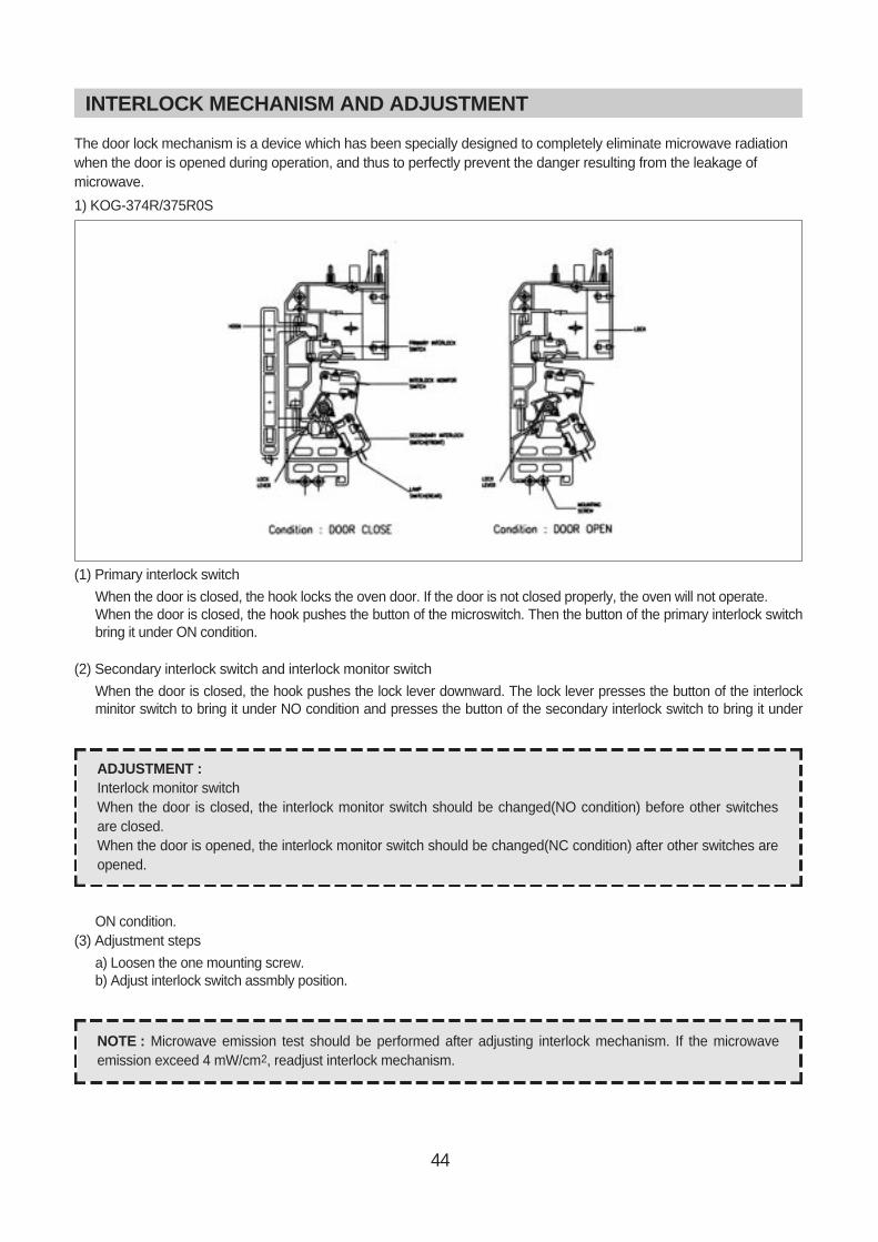
The door lock mechanism is a device which has been specially designed to completely eliminate microwave radiationwhen the door is opened during operation, and thus to perfectly prevent the danger resulting from the leakage ofmicrowave.
(1) Primary interlock switch
When the door is closed, the hook locks the oven door. If the door is not closed properly, the oven will not operate.When the door is closed, the hook pushes the button of the microswitch. Then the button of the primary interlock switchbring it under ON condition.
(2) Secondary interlock switch and interlock monitor switch
When the door is closed, the hook pushes the lock lever downward. The lock lever presses the button of the interlockminitor switch to bring it under NO condition and presses the button of the secondary interlock switch to bring it underON condition.
(3) Adjustment steps
a) Loosen the one mounting screw.b) Adjust interlock switch assmbly position.c) Make sure that lock lever moves smoothly after adjustment is completed.d) Tighten completely one mounting screw.
ADJUSTMENT :Interlock monitor switchWhen the door is closed, the interlock monitor switch should be changed(NO condition) before other switchesare closed.When the door is opened, the interlock monitor switch should be changed(NC condition) after other switches areopened.
NOTE : Microwave emission test should be performed after adjusting interlock mechanism. If the microwaveemission exceed 4 mW/cm2, readjust interlock mechanism.
44
INTERLOCK MECHANISM AND ADJUSTMENT
The door lock mechanism is a device which has been specially designed to completely eliminate microwave radiationwhen the door is opened during operation, and thus to perfectly prevent the danger resulting from the leakage ofmicrowave.
1) KOG-374R/375R0S
(1) Primary interlock switch
When the door is closed, the hook locks the oven door. If the door is not closed properly, the oven will not operate.When the door is closed, the hook pushes the button of the microswitch. Then the button of the primary interlock switchbring it under ON condition.
(2) Secondary interlock switch and interlock monitor switch
When the door is closed, the hook pushes the lock lever downward. The lock lever presses the button of the interlockminitor switch to bring it under NO condition and presses the button of the secondary interlock switch to bring it under
ON condition.(3) Adjustment steps
a) Loosen the one mounting screw.b) Adjust interlock switch assmbly position.
ADJUSTMENT :Interlock monitor switchWhen the door is closed, the interlock monitor switch should be changed(NO condition) before other switchesare closed.When the door is opened, the interlock monitor switch should be changed(NC condition) after other switches areopened.
NOTE : Microwave emission test should be performed after adjusting interlock mechanism. If the microwaveemission exceed 4 mW/cm2, readjust interlock mechanism.
4545
Following the procedure below to check if the oven is defective or not.
1) Check earthing before trouble checking.2) Be careful of the high voltage circuit.3) Discharge the high voltage capacitor.4) When checking the continuity of the switches, fuse or high voltage tranformer, disconnect one load wire from these
parts and check continuity with the AC plug removed. To do otherwise may result in a false reading or damage toyour meter.
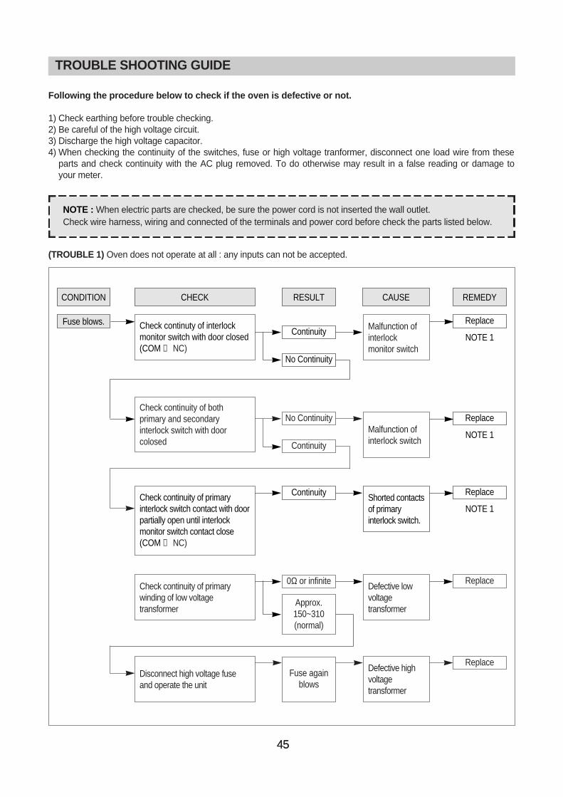
(TROUBLE 1) Oven does not operate at all : any inputs can not be accepted.
TROUBLE SHOOTING GUIDE
NOTE : When electric parts are checked, be sure the power cord is not inserted the wall outlet.Check wire harness, wiring and connected of the terminals and power cord before check the parts listed below.
CONDITION CHECK
Check continuty of interlockmonitor switch with door closed(COM ↔ NC)
Check continuity of bothprimary and secondaryinterlock switch with doorcolosed
Malfunction ofinterlockmonitor switch
Malfunction ofinterlock switch
RESULT
Continuity
No Continuity
CAUSE REMEDY
Replace
NOTE 1
Fuse blows.
Replace
NOTE 1
Shorted contactsof primaryinterlock switch.
Continuity Replace
NOTE 1Check continuity of primaryinterlock switch contact with doorpartially open until interlockmonitor switch contact close(COM ↔ NC)
Defective lowvoltagetransformer
0Ω or infinite
Approx.150~310(normal)
ReplaceCheck continuity of primarywinding of low voltagetransformer
Defective highvoltagetransformer
Fuse againblows
ReplaceDisconnect high voltage fuseand operate the unit
No Continuity
Continuity
TROUBLE SHOOTING GUIDE
46
TROUBLE SHOOTING GUIDE
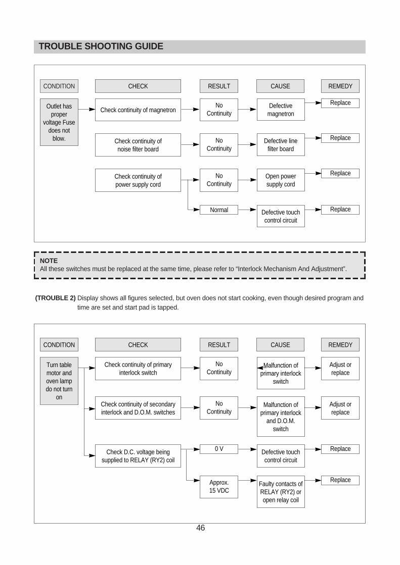
CONDITION CHECK
Check continuity of magnetronDefective
magnetron
RESULT
NoContinuity
CAUSE REMEDY
ReplaceOutlet hasproper
voltage Fusedoes not
blow.
CONDITION CHECK
Check continuity of primaryinterlock switch
Malfunction ofprimary interlock
switch
RESULT
NoContinuity
CAUSE REMEDY
Adjust orreplace
Turn tablemotor andoven lampdo not turn
onCheck continuity of secondaryinterlock and D.O.M. switches
Malfunction ofprimary interlock
and D.O.M. switch
NoContinuity
Adjust orreplace
Check D.C. voltage beingsupplied to RELAY (RY2) coil
Defective touchcontrol circuit
0 V Replace
Faulty contacts ofRELAY (RY2) oropen relay coil
Approx.15 VDC
Replace
Check continuity of noise filter board
Defective line filter board
NoContinuity
Replace
Check continuity ofpower supply cord
Open powersupply cord
NoContinuity
Replace
Defective touchcontrol circuit
Normal Replace
NOTEAll these switches must be replaced at the same time, please refer to “Interlock Mechanism And Adjustment”.
(TROUBLE 2) Display shows all figures selected, but oven does not start cooking, even though desired program andtime are set and start pad is tapped.
47
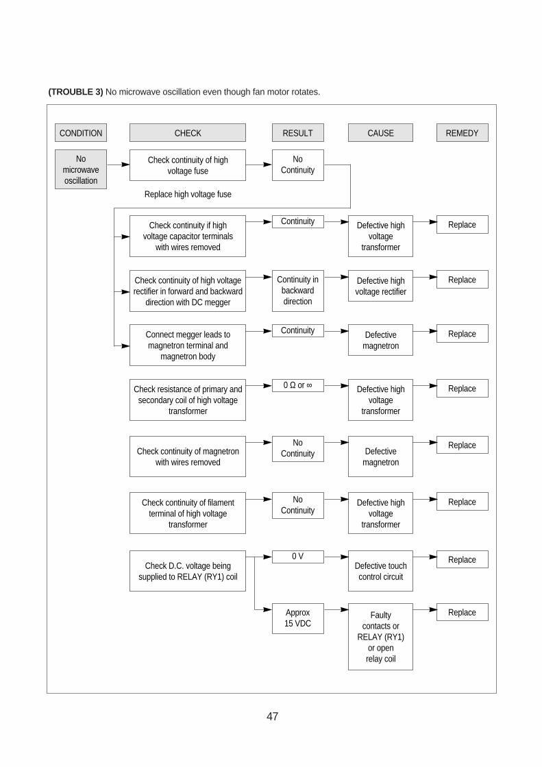
CONDITION CHECK
Check continuity of highvoltage fuse
RESULT
NoContinuity
Check continuity if high voltage capacitor terminals
with wires removed
Replace high voltage fuse
Continuity
CAUSE
Defective highvoltage
transformer
REMEDY
Replace
Nomicrowaveoscillation
Check continuity of high voltagerectifier in forward and backward
direction with DC megger
Continuity inbackwarddirection
Defective highvoltage rectifier
Replace
Connect megger leads tomagnetron terminal and
magnetron body
Continuity Defectivemagnetron
Replace
Check resistance of primary andsecondary coil of high voltage
transformer
0 Ω or ∞ Defective highvoltage
transformer
Replace
Check continuity of magnetronwith wires removed
NoContinuity Defective
magnetron
Replace
Check continuity of filamentterminal of high voltage
transformer
NoContinuity
Defective highvoltage
transformer
Replace
Check D.C. voltage beingsupplied to RELAY (RY1) coil
0 VDefective touchcontrol circuit
Replace
Approx15 VDC
Faultycontacts or
RELAY (RY1)or openrelay coil
Replace
(TROUBLE 3) No microwave oscillation even though fan motor rotates.

48
(TROUBLE 4) The following visual conditions inditions indicate a probable defective touch control circuit ormembrane switch assembly
1. Incomplete segments,1) Segments missing.2) Partical segments missing.3) Digit flickering other than normal display slight flickering.4) " :0" does not display when power is on.
2. A distinct change in the display are not on when they numbers isthe display.
3. One or more digits in the display are not on when they should be.
4. Display indicates a number different from one touched.
5. Specific numbers (for example 2 or 3) will not display when the panel is touched.
6. Display does not count down or up with time cooking or clock operation.
7. Oven is programmable and cooks normally but no display shows.
8. Display obviously jumps in time while counting down.
9. Display counts down noticeable too fast while cooking.
10. Display does not show the time of day when dlear pad is touched.
11. Oven lamp and turntable motor do not stop although cooking is finished. Check if the RELAY 2 contacts close if theyare close, replace touch control circuit.
NOTE (KOG-371G/H, KOG-391G/H)Before following the particular steps listed above in the trouble shooting guide for the membrane keyboard's,failure, please check for the continuity of each wire-harness between the membrane keyboard and P.C.B.assembly.
CONDITION CHECK
Check rach pad forcontinuity of the membranekeyboard for the followingkeyboard check procedure
Malfunctionof touch
control circuitof control boxsub-assembly
RESULT
Normal
CAUSE REMEDY
Replacecontrol box
sub-assembly
Malfunctionof the membrane
keyboard
Abnormal Replace themembranekeyboard
Display doesnot show
programmingat all, even ifkeyboard is
touched.
49
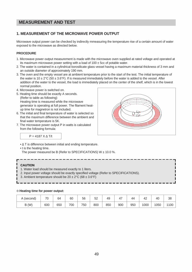
1. MEASUREMENT OF THE MICROWAVE POWER OUTPUT
Microwave output power can be checked by indirectly mmeasuring the temperature rise of a certain amount of waterexposed to the microwave as directed below.
PROCEDURE
1. Microwave power output measurement is made with the microwave oven supplied at rated voltage and operated atits maximum microwave power setting with a load of 100 ± 5cc of potable water.
2. The water is contained in a cylindrical borosilicate glass vessel having a maximum material thickness of 3 mm andan outside diameter of approximately 190 mm.
3. The oven and the empty vessel are at ambient temperature prior to the start of the test. The initial temperature ofthe water is 10 ± 2°C (50 ± 3.6°F). If is measured immediately before the water is added to the vessel. Afteraddition of the water to the vessel, the load is immediately placed on the center of the shelf, which is in the lowestnormal position.
4. Microwave power is switched on.5. Heating time should be exactly A seconds.
(Refer to table as following)Heating time is measured while the microwavegenerator is operating at full power. The filament heat-up time for magnetron is not included.
6. The initial and final temperature of water is selected sothat the maximum difference between the ambient andfinal water temperature is 5K.
7. The microwave power output P in watts is calculatedfrom the following formula:
• ∆ T is difference between initial and ending temperature.• t is the heating time.The power measured be B (Refer to SPECIFICATIONS) W ± 10.0 %.
Heating time for power output:
CAUTION1. Water load should be measured exactly to 1 liters.2. Input power voltage should be exactly specified voltage (Refer to SPECIFICATIONS).3. Ambient temperature should be 20 ± 2°C (68 ± 3.6°F)
P = 4187 X ∆ T/t
70
600
64
650
60
700
56
750
52
800
49
850
47
900
44
950
42
1000
40
1050
38
1100
A (second)
B (W)
MEASUREMENT AND TEST
50
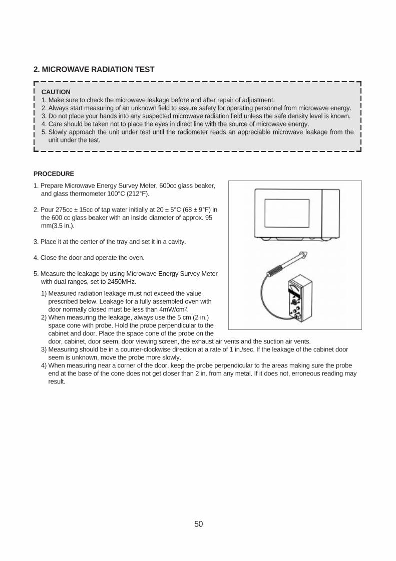
2. MICROWAVE RADIATION TEST
PROCEDURE
1. Prepare Microwave Energy Survey Meter, 600cc glass beaker,and glass thermometer 100°C (212°F).
2. Pour 275cc ± 15cc of tap water initially at 20 ± 5°C (68 ± 9°F) inthe 600 cc glass beaker with an inside diameter of approx. 95mm(3.5 in.).
3. Place it at the center of the tray and set it in a cavity.
4. Close the door and operate the oven.
5. Measure the leakage by using Microwave Energy Survey Meterwith dual ranges, set to 2450MHz.
1) Measured radiation leakage must not exceed the valueprescribed below. Leakage for a fully assembled oven withdoor normally closed must be less than 4mW/cm2.
2) When measuring the leakage, always use the 5 cm (2 in.)space cone with probe. Hold the probe perpendicular to thecabinet and door. Place the space cone of the probe on thedoor, cabinet, door seem, door viewing screen, the exhaust air vents and the suction air vents.
3) Measuring should be in a counter-clockwise direction at a rate of 1 in./sec. If the leakage of the cabinet doorseem is unknown, move the probe more slowly.
4) When measuring near a corner of the door, keep the probe perpendicular to the areas making sure the probeend at the base of the cone does not get closer than 2 in. from any metal. If it does not, erroneous reading mayresult.
CAUTION1. Make sure to check the microwave leakage before and after repair of adjustment.2. Always start measuring of an unknown field to assure safety for operating personnel from microwave energy.3. Do not place your hands into any suspected microwave radiation field unless the safe density level is known.4. Care should be taken not to place the eyes in direct line with the source of microwave energy.5. Slowly approach the unit under test until the radiometer reads an appreciable microwave leakage from the
unit under the test.
51
3. COMPONENT TEST PROCEDURE
• High voltage is present at the high voltage terminal of the high voltage transformer during any cooking cycle.• It is neither necessary nor advisable to attempt measurement of the high voltage.• Before touching any oven components or wiring, always unplug the oven from its power source and discharge the
capacitor.
1. High voltage transformer
1) Remove connections from the transformer terminals and check continuity.2) Normal readings should be as follows :
Secondary winding ... Approx. 110 Ω±10%Filament winding ... Approx. 0 ΩPrimary winding ... Approx. 1 Ω
2. High voltage capacitor
1) Check continuity of capacitor with meter on the highest OHM scale.2) A normal capacitor will show continuity for a short time, and then indicate 10MΩ once the capacitor charged.3) A shorted capacitor will show continuous continuity.4) An open capacitor will show constant 10MΩ.5) Resistance between each terminal and chassis should be infinite.
3. High voltage diode
1) Isolate the diode from the circuit by disconnecting the leads.2) With the ohmmeter set on the highest resistance scale measure the resistance across the diode terminals.
Reverse the meter leads and again observe the resistance reading. Meter with 6V, 9V or higher voltage batteriesshould be used to check the front-back resistance of the diode, otherwise an infinite resistance may be read inboth directions. A normal diode's resistance will be infinite in one direction and several hundred k Ω in the otherdirection.
4. Magnetron
For complete magnetron diagnosis, refer to "Measurement of the Microwave Power Output." Continuity checks canonly indicate and open filament or a shorted magnetron. To diagnose for an open filament or a shorted magnetron,1) Isolate magnetron from the circuit by disconnecting the leads.2) A continuity check across magnetron filament terminals should indicate 0.1 Ω or less.3) A continuity check between each filament terminal and magnetron case should read open.
5. Fuse
If the fuse in the primary and monitor switch circuit is blown when the door is opened, check the primary andmonitor switch before replacing the blown fuse. In case the fuse is blown by an improper switch operation, replacethe defective switch and fuse at the same time. Replace just the fuse if the switches operate normally.
52
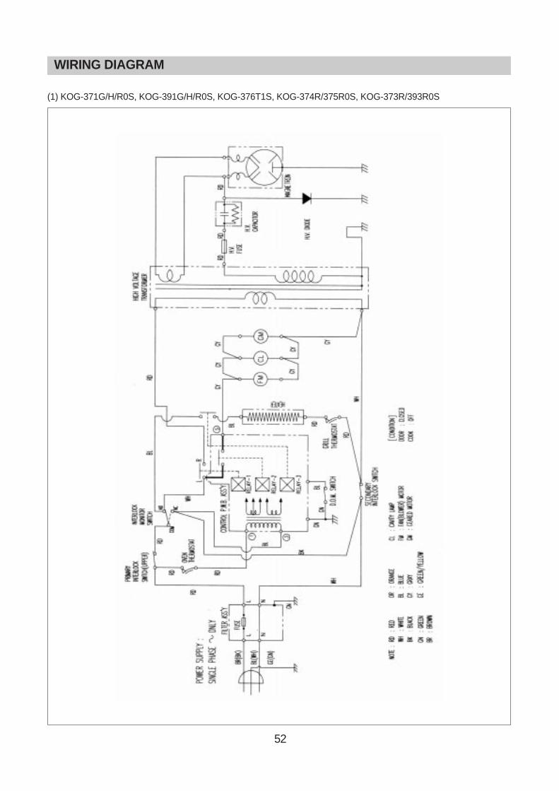
WIRING DIAGRAM
(1) KOG-371G/H/R0S, KOG-391G/H/R0S, KOG-376T1S, KOG-374R/375R0S, KOG-373R/393R0S
53
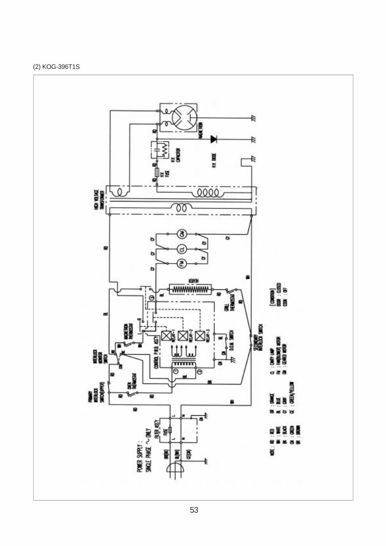
(2) KOG-396T1S

54
1. CIRCUIT CHECK PROCEDURE
1. Low voltage transformer check
The low voltage transformer is located on the P.C.B.Measuring condition: Input voltage: 230V / Frequency: 50Hz
2. Voltage Check
- Key check point
- Check method
NOTE1. Refer to Ciruit Diagram (point 4).2. Secondary side voltage of the low voltage transformer changes in proportion to fluctuation of power source
voltage.3. The allowable tolerance of the secondary voltage is within ± 5% of nominal voltage.
NOTEEach measure point must be measured with GND points.
Terminal Voltage
4-7
LOAD
AC 25.8 V
NO LOAD
AC 28.4 V
PRINTED CIRCUIT BOARD <KOG-371G/H0S, KOG-391G/H0S>
NO CHECK POINT REMARK
1 IC1 PIN 2, 21, 30, 34 -5VDC
2 IC1 PIN 35
3 IC1 PIN 31 OR 32
T : 20ms(50Hz)
T : 250 ns(4MHz)
NO MEASURE POINT WAVE FORM REMEDY REMARK
1 MP1 DC -5V±0.25V Replace VL1, EC1 NO LOAD
2 MP2 DC -12V±2.0V Replace EC2, D12,13,14 NO LOAD

55
Mesurement point

56
3. When there is no microwave oscillation1) When touching START pad, oven lamp does not turn on.
Fan motor do not rotate, but cook indicator in display comes on. Cause : RELAY 2 does not operate. → refer to Circuit Diagram (point 3)- Check method
2) When touching START pad, oven lamp turns on.Fan motor and turntable rotate and cook indicator in display comes on. Cause : RELAY 1 does not operate. → refer to Circuit Diagram (point 2)- Check method
4. When there is no grill oscillation. Cause : RELAY 3 does not operate. → refer to Circuit Diagram (point 6)- Check method
5. When the door is opened during operation, the count down timer does not stop.
→ refer to Circuit Diagram (point 1)- Check method
6. When the digital clock does not operate properly.→ refer to Circuit Diagram (point 5)
If clock does not keep exact time, you must check resistor R15,16, zener diode ZD1.
POINTA BSTATE
RELAY 2 ON -5VDC GND
RELAY 2 OFF GND -12VDC
POINTA BSTATE
RELAY 1 ON -5VDC GND
RELAY 1 OFF GND -12VDC
POINTA BSTATE
RELAY 3 ON -5VDC GND
RELAY 3 OFF GND -12VDC
POINTA BSTATE
1) DOOR OPEN OPEN -5VDC
2) DOOR CLOSED CLOSE GND
CHECK NO HETHOD REMEDY
1 Check the stage(ON, OFF) of the door open monitor Replace door open monitor switch.switch by resistance measurement.
POINT WAVE FORM
A T: 20 ms(50Hz)

57
2. P.C.B. CIRCUIT DIAGRAM
58
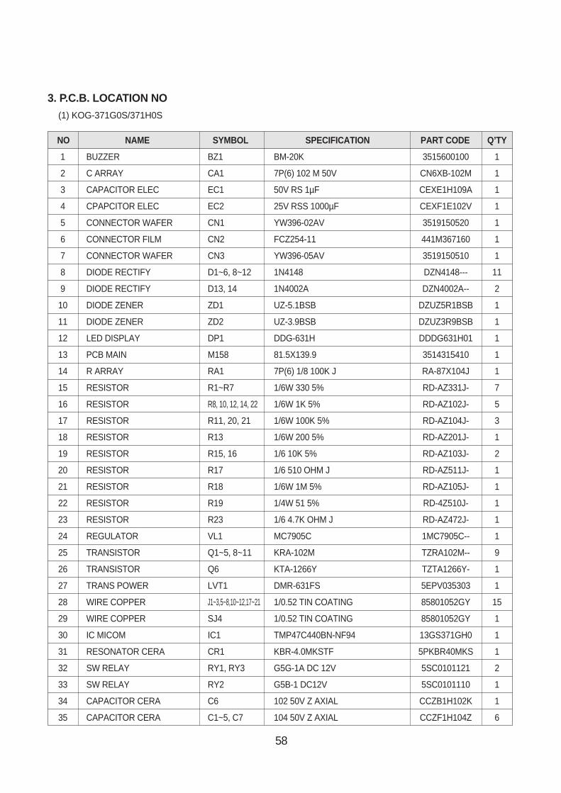
NO NAME SYMBOL SPECIFICATION PART CODE Q’TY
1 BUZZER BZ1 BM-20K 3515600100 1
2 C ARRAY CA1 7P(6) 102 M 50V CN6XB-102M 1
3 CAPACITOR ELEC EC1 50V RS 1µF CEXE1H109A 1
4 CPAPCITOR ELEC EC2 25V RSS 1000µF CEXF1E102V 1
5 CONNECTOR WAFER CN1 YW396-02AV 3519150520 1
6 CONNECTOR FILM CN2 FCZ254-11 441M367160 1
7 CONNECTOR WAFER CN3 YW396-05AV 3519150510 1
8 DIODE RECTIFY D1~6, 8~12 1N4148 DZN4148--- 11
9 DIODE RECTIFY D13, 14 1N4002A DZN4002A-- 2
10 DIODE ZENER ZD1 UZ-5.1BSB DZUZ5R1BSB 1
11 DIODE ZENER ZD2 UZ-3.9BSB DZUZ3R9BSB 1
12 LED DISPLAY DP1 DDG-631H DDDG631H01 1
13 PCB MAIN M158 81.5X139.9 3514315410 1
14 R ARRAY RA1 7P(6) 1/8 100K J RA-87X104J 1
15 RESISTOR R1~R7 1/6W 330 5% RD-AZ331J- 7
16 RESISTOR R8, 10, 12, 14, 22 1/6W 1K 5% RD-AZ102J- 5
17 RESISTOR R11, 20, 21 1/6W 100K 5% RD-AZ104J- 3
18 RESISTOR R13 1/6W 200 5% RD-AZ201J- 1
19 RESISTOR R15, 16 1/6 10K 5% RD-AZ103J- 2
20 RESISTOR R17 1/6 510 OHM J RD-AZ511J- 1
21 RESISTOR R18 1/6W 1M 5% RD-AZ105J- 1
22 RESISTOR R19 1/4W 51 5% RD-4Z510J- 1
23 RESISTOR R23 1/6 4.7K OHM J RD-AZ472J- 1
24 REGULATOR VL1 MC7905C 1MC7905C-- 1
25 TRANSISTOR Q1~5, 8~11 KRA-102M TZRA102M-- 9
26 TRANSISTOR Q6 KTA-1266Y TZTA1266Y- 1
27 TRANS POWER LVT1 DMR-631FS 5EPV035303 1
28 WIRE COPPER J1~3,5~8,10~12,17~21 1/0.52 TIN COATING 85801052GY 15
29 WIRE COPPER SJ4 1/0.52 TIN COATING 85801052GY 1
30 IC MICOM IC1 TMP47C440BN-NF94 13GS371GH0 1
31 RESONATOR CERA CR1 KBR-4.0MKSTF 5PKBR40MKS 1
32 SW RELAY RY1, RY3 G5G-1A DC 12V 5SC0101121 2
33 SW RELAY RY2 G5B-1 DC12V 5SC0101110 1
34 CAPACITOR CERA C6 102 50V Z AXIAL CCZB1H102K 1
35 CAPACITOR CERA C1~5, C7 104 50V Z AXIAL CCZF1H104Z 6
3. P.C.B. LOCATION NO(1) KOG-371G0S/371H0S
59
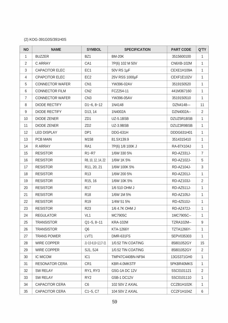
NO NAME SYMBOL SPECIFICATION PART CODE Q’TY
1 BUZZER BZ1 BM-20K 3515600100 1
2 C ARRAY CA1 7P(6) 102 M 50V CN6XB-102M 1
3 CAPACITOR ELEC EC1 50V RS 1µF CEXE1H109A 1
4 CPAPCITOR ELEC EC2 25V RSS 1000µF CEXF1E102V 1
5 CONNECTOR WAFER CN1 YW396-02AV 3519150520 1
6 CONNECTOR FILM CN2 FCZ254-11 441M367160 1
7 CONNECTOR WAFER CN3 YW396-05AV 3519150510 1
8 DIODE RECTIFY D1~6, 8~12 1N4148 DZN4148--- 11
9 DIODE RECTIFY D13, 14 1N4002A DZN4002A-- 2
10 DIODE ZENER ZD1 UZ-5.1BSB DZUZ5R1BSB 1
11 DIODE ZENER ZD2 UZ-3.9BSB DZUZ3R9BSB 1
12 LED DISPLAY DP1 DDG-631H DDDG631H01 1
13 PCB MAIN M158 81.5X139.9 3514315410 1
14 R ARRAY RA1 7P(6) 1/8 100K J RA-87X104J 1
15 RESISTOR R1~R7 1/6W 330 5% RD-AZ331J- 7
16 RESISTOR R8, 10, 12, 14, 22 1/6W 1K 5% RD-AZ102J- 5
17 RESISTOR R11, 20, 21 1/6W 100K 5% RD-AZ104J- 3
18 RESISTOR R13 1/6W 200 5% RD-AZ201J- 1
19 RESISTOR R15, 16 1/6W 10K 5% RD-AZ103J- 2
20 RESISTOR R17 1/6 510 OHM J RD-AZ511J- 1
21 RESISTOR R18 1/6W 1M 5% RD-AZ105J- 1
22 RESISTOR R19 1/4W 51 5% RD-4Z510J- 1
23 RESISTOR R23 1/6 4.7K OHM J RD-AZ472J- 1
24 REGULATOR VL1 MC7905C 1MC7905C-- 1
25 TRANSISTOR Q1~5, 8~11 KRA-102M TZRA102M-- 9
26 TRANSISTOR Q6 KTA-1266Y TZTA1266Y- 1
27 TRANS POWER LVT1 DMR-631FS 5EPV035303 1
28 WIRE COPPER J1~3,5~8,10~12,17~21 1/0.52 TIN COATING 85801052GY 15
29 WIRE COPPER SJ1, SJ4 1/0.52 TIN COATING 85801052GY 2
30 IC MICOM IC1 TMP47C440BN-NF94 13GS371GH0 1
31 RESONATOR CERA CR1 KBR-4.0MKSTF 5PKBR40MKS 1
32 SW RELAY RY1, RY3 G5G-1A DC 12V 5SC0101121 2
33 SW RELAY RY2 G5B-1 DC12V 5SC0101110 1
34 CAPACITOR CERA C6 102 50V Z AXIAL CCZB1H102K 1
35 CAPACITOR CERA C1~5, C7 104 50V Z AXIAL CCZF1H104Z 6
(2) KOG-391G0S/391H0S
60
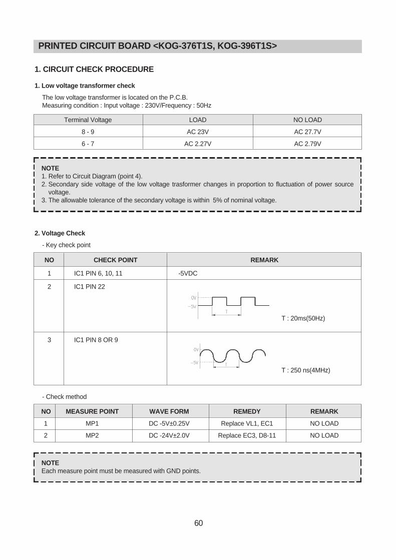
1. CIRCUIT CHECK PROCEDURE
1. Low voltage transformer check
The low voltage transformer is located on the P.C.B.Measuring condition : Input voltage : 230V/Frequency : 50Hz
2. Voltage Check
- Key check point
- Check method
NOTE1. Refer to Circuit Diagram (point 4).2. Secondary side voltage of the low voltage trasformer changes in proportion to fluctuation of power source
voltage.3. The allowable tolerance of the secondary voltage is within 5% of nominal voltage.
NOTEEach measure point must be measured with GND points.
PRINTED CIRCUIT BOARD <KOG-376T1S, KOG-396T1S>
Terminal Voltage
8 - 9
6 - 7
LOAD
AC 23V
AC 2.27V
NO LOAD
AC 27.7V
AC 2.79V
NO CHECK POINT REMARK
1 IC1 PIN 6, 10, 11 -5VDC
2 IC1 PIN 22
3 IC1 PIN 8 OR 9
T : 20ms(50Hz)
T : 250 ns(4MHz)
NO MEASURE POINT WAVE FORM REMEDY REMARK
1 MP1 DC -5V±0.25V Replace VL1, EC1 NO LOAD
2 MP2 DC -24V±2.0V Replace EC3, D8-11 NO LOAD
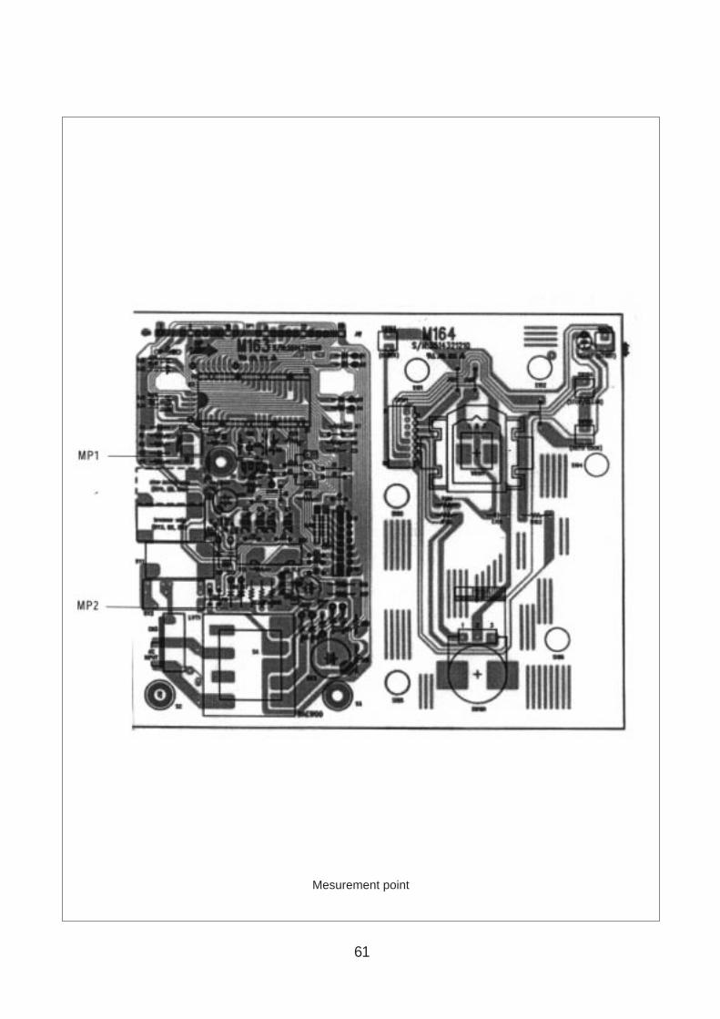
61
Mesurement point
62
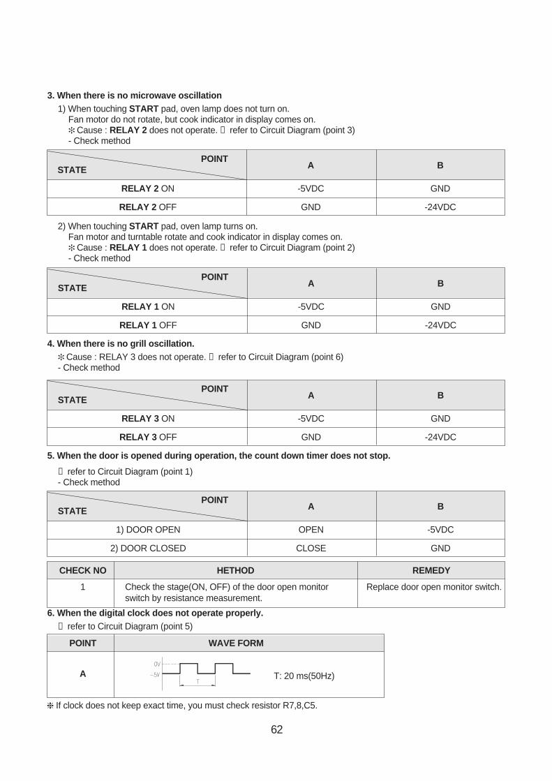
3. When there is no microwave oscillation1) When touching START pad, oven lamp does not turn on.
Fan motor do not rotate, but cook indicator in display comes on. Cause : RELAY 2 does not operate. → refer to Circuit Diagram (point 3)- Check method
2) When touching START pad, oven lamp turns on.Fan motor and turntable rotate and cook indicator in display comes on. Cause : RELAY 1 does not operate. → refer to Circuit Diagram (point 2)- Check method
4. When there is no grill oscillation. Cause : RELAY 3 does not operate. → refer to Circuit Diagram (point 6)- Check method
5. When the door is opened during operation, the count down timer does not stop.
→ refer to Circuit Diagram (point 1)- Check method
6. When the digital clock does not operate properly.→ refer to Circuit Diagram (point 5)
If clock does not keep exact time, you must check resistor R7,8,C5.
POINTA BSTATE
RELAY 2 ON -5VDC GND
RELAY 2 OFF GND -24VDC
POINTA BSTATE
RELAY 1 ON -5VDC GND
RELAY 1 OFF GND -24VDC
POINTA BSTATE
RELAY 3 ON -5VDC GND
RELAY 3 OFF GND -24VDC
POINTA BSTATE
1) DOOR OPEN OPEN -5VDC
2) DOOR CLOSED CLOSE GND
CHECK NO HETHOD REMEDY
1 Check the stage(ON, OFF) of the door open monitor Replace door open monitor switch.switch by resistance measurement.
POINT WAVE FORM
A T: 20 ms(50Hz)
63
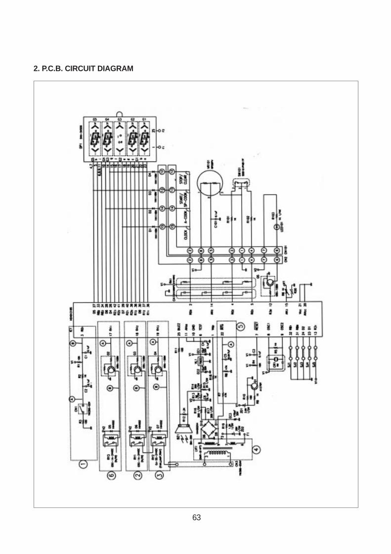
2. P.C.B. CIRCUIT DIAGRAM
64
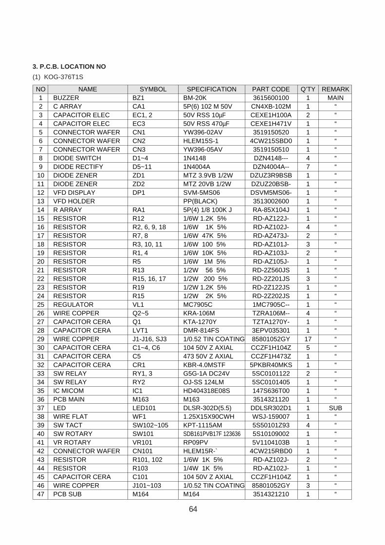
3. P.C.B. LOCATION NO
(1) KOG-376T1S
NO NAME SYMBOL SPECIFICATION PART CODE Q’TY REMARK1 BUZZER BZ1 BM-20K 3615600100 1 MAIN2 C ARRAY CA1 5P(6) 102 M 50V CN4XB-102M 1 “3 CAPACITOR ELEC EC1, 2 50V RSS 10µF CEXE1H100A 2 “4 CAPACITOR ELEC EC3 50V RSS 470µF CEXE1H471V 1 “5 CONNECTOR WAFER CN1 YW396-02AV 3519150520 1 “6 CONNECTOR WAFER CN2 HLEM15S-1 4CW215SBD0 1 “7 CONNECTOR WAFER CN3 YW396-05AV 3519150510 1 “8 DIODE SWITCH D1~4 1N4148 DZN4148--- 4 “9 DIODE RECTIFY D5~11 1N4004A DZN4004A-- 7 “
10 DIODE ZENER ZD1 MTZ 3.9VB 1/2W DZUZ3R9BSB 1 “11 DIODE ZENER ZD2 MTZ 20VB 1/2W DZUZ20BSB- 1 “12 VFD DISPLAY DP1 SVM-5MS06 DSVM5MS06- 1 “13 VFD HOLDER PP(BLACK) 3513002600 1 “14 R ARRAY RA1 5P(4) 1/8 100K J RA-85X104J 1 “15 RESISTOR R12 1/6W 1.2K 5% RD-AZ122J- 1 “16 RESISTOR R2, 6, 9, 18 1/6W 1K 5% RD-AZ102J- 4 “17 RESISTOR R7, 8 1/6W 47K 5% RD-AZ473J- 2 “18 RESISTOR R3, 10, 11 1/6W 100 5% RD-AZ101J- 3 “19 RESISTOR R1, 4 1/6W 10K 5% RD-AZ103J- 2 “20 RESISTOR R5 1/6W 1M 5% RD-AZ105J- 1 “21 RESISTOR R13 1/2W 56 5% RD-2Z560JS 1 “22 RESISTOR R15, 16, 17 1/2W 200 5% RD-2Z201JS 3 “23 RESISTOR R19 1/2W 1.2K 5% RD-2Z122JS 1 “24 RESISTOR R15 1/2W 2K 5% RD-2Z202JS 1 “25 REGULATOR VL1 MC7905C 1MC7905C-- 1 “26 WIRE COPPER Q2~5 KRA-106M TZRA106M-- 4 “27 CAPACITOR CERA Q1 KTA-1270Y TZTA1270Y- 1 “28 CAPACITOR CERA LVT1 DMR-814FS 3EPV035301 1 “29 WIRE COPPER J1-J16, SJ3 1/0.52 TIN COATING 85801052GY 17 “30 CAPACITOR CERA C1~4, C6 104 50V Z AXIAL CCZF1H104Z 5 “31 CAPACITOR CERA C5 473 50V Z AXIAL CCZF1H473Z 1 “32 CAPACITOR CERA CR1 KBR-4.0MSTF 5PKBR40MKS 1 “33 SW RELAY RY1, 3 G5G-1A DC24V 5SC0101122 2 “34 SW RELAY RY2 OJ-SS 124LM 5SC0101405 1 “35 IC MICOM IC1 HD404318E08S 147S636T00 1 “36 PCB MAIN M163 M163 3514321120 1 “37 LED LED101 DLSR-302D(5.5) DDLSR302D1 1 SUB38 WIRE FLAT WF1 1.25X15X90CWH WSJ-159007 1 “39 SW TACT SW102~105 KPT-1115AM 5S50101Z93 4 “40 SW ROTARY SW101 SDB161PVB17F 123636 5S10109002 1 “41 VR ROTARY VR101 RP09PV 5V1104103B 1 “42 CONNECTOR WAFER CN101 HLEM15R-` 4CW215RBD0 1 “43 RESISTOR R101, 102 1/6W 1K 5% RD-AZ102J- 2 “44 RESISTOR R103 1/4W 1K 5% RD-AZ102J- 1 “45 CAPACITOR CERA C101 104 50V Z AXIAL CCZF1H104Z 1 “46 WIRE COPPER J101~103 1/0.52 TIN COATING 85801052GY 3 “47 PCB SUB M164 M164 3514321210 1 “

65
(2) KOG-396T1S
NO NAME SYMBOL SPECIFICATION PART CODE Q’TY REMARK1 BUZZER BZ1 BM-20K 3615600100 1 MAIN2 C ARRAY CA1 5P(6) 102 M 50V CN4XB-102M 1 “3 CAPACITOR ELEC EC1, 2 50V RSS 10µF CEXE1H100A 2 “4 CAPACITOR ELEC EC3 50V RSS 470µF CEXE1H471V 1 “5 CONNECTOR WAFER CN1 YW396-02AV 3519150520 1 “6 CONNECTOR WAFER CN2 HLEM15S-1 4CW215SBD0 1 “7 CONNECTOR WAFER CN3 YW396-05AV 3519150510 1 “8 DIODE SWITCH D1~4 1N4148 DZN4148--- 4 “9 DIODE RECTIFY D5~11 1N4004A DZN4004A-- 7 “
10 DIODE ZENER ZD1 MTZ 3.9VB 1/2W DZUZ3R9BSB 1 “11 DIODE ZENER ZD2 MTZ 20VB 1/2W DZUZ20BSB- 1 “12 VFD DISPLAY DP1 SVM-5MS06 DSVM5MS06- 1 “13 VFD HOLDER PP(BLACK) 3513002600 1 “14 R ARRAY RA1 5P(4) 1/8 100K J RA-85X104J 1 “15 RESISTOR R12 1/6W 1.2K 5% RD-AZ122J- 1 “16 RESISTOR R2, 6, 9, 18 1/6W 1K 5% RD-AZ102J- 4 “17 RESISTOR R7, 8 1/6W 47K 5% RD-AZ473J- 2 “18 RESISTOR R3, 10, 11 1/6W 100 5% RD-AZ101J- 3 “19 RESISTOR R1, 4 1/6W 10K 5% RD-AZ103J- 2 “20 RESISTOR R5 1/6W 1M 5% RD-AZ105J- 1 “21 RESISTOR R13 1/2W 56 5% RD-2Z560JS 1 “22 RESISTOR R15, 16, 17 1/2W 200 5% RD-2Z201JS 3 “23 RESISTOR R19 1/2W 1.2K 5% RD-2Z122JS 1 “24 RESISTOR R15 1/2W 2K 5% RD-2Z202JS 1 “25 REGULATOR VL1 MC7905C 1MC7905C-- 1 “26 WIRE COPPER Q2~5 KRA-106M TZRA106M-- 4 “27 CAPACITOR CERA Q1 KTA-1270Y TZTA1270Y- 1 “28 CAPACITOR CERA LVT1 DMR-814FS 3EPV035301 1 “29 WIRE COPPER J1-J16, SJ3 1/0.52 TIN COATING 85801052GY 17 “30 CAPACITOR CERA C1~4, C6 104 50V Z AXIAL CCZF1H104Z 5 “31 CAPACITOR CERA C5 473 50V Z AXIAL CCZF1H473Z 1 “32 CAPACITOR CERA CR1 KBR-4.0MSTF 5PKBR40MKS 1 “33 SW RELAY RY1, 3 G5G-1A DC24V 5SC0101122 2 “34 SW RELAY RY2 OJ-SS 124LM 5SC0101405 1 “35 IC MICOM IC1 HD404318E08S 147S636T00 1 “36 PCB MAIN M163 M163 3514321120 1 “37 LED LED101 DLSR-302D(5.5) DDLSR302D1 1 SUB38 WIRE FLAT WF1 1.25X15X90CWH WSJ-159007 1 “39 SW TACT SW102~105 KPT-1115AM 5S50101Z93 4 “40 SW ROTARY SW101 SDB161PVB17F 123636 5S10109002 1 “41 VR ROTARY VR101 RP09PV 5V1104103B 1 “42 CONNECTOR WAFER CN101 HLEM15R-` 4CW215RBD0 1 “43 RESISTOR R101, 102 1/6W 1K 5% RD-AZ102J- 2 “44 RESISTOR R103 1/4W 1K 5% RD-AZ102J- 1 “45 CAPACITOR CERA C101 104 50V Z AXIAL CCZF1H104Z 1 “46 WIRE COPPER J101~103 1/0.52 TIN COATING 85801052GY 3 “47 PCB SUB M164 M164 3514321210 1 “

66
1. CIRCUIT CHECK PROCEDURE
1. Low voltage transformer check
The low voltage transformer is located on the P.C.B.Measuring condition: Input voltage: 230V / Frequency: 50Hz
2. Voltage Check
- Key check point
- Check method
NOTE1. Refer to Ciruit Diagram (point 4).2. Secondary side voltage of the low voltage transformer changes in proportion to fluctuation of power source
voltage.3. The allowable tolerance of the secondary voltage is within ± 5% of nominal voltage.
NOTEEach measure point must be measured with GND points.
Terminal Voltage
4-7
LOAD
AC 25.8 V
NO LOAD
AC 28.4 V
PRINTED CIRCUIT BOARD <KOG-371R0S, KOG-391R0S>
NO CHECK POINT REMARK
1 IC1 PIN 2, 21, 30, 34 -5VDC
2 IC1 PIN 35
3 IC1 PIN 31 OR 32
T : 20ms(50Hz)
T : 250 ns(4MHz)
NO MEASURE POINT WAVE FORM REMEDY REMARK
1 MP1 DC -5V±0.25V Replace VL1, EC1 NO LOAD
2 MP2 DC -12V±2.0V Replace EC2, D6, 11, 12 NO LOAD
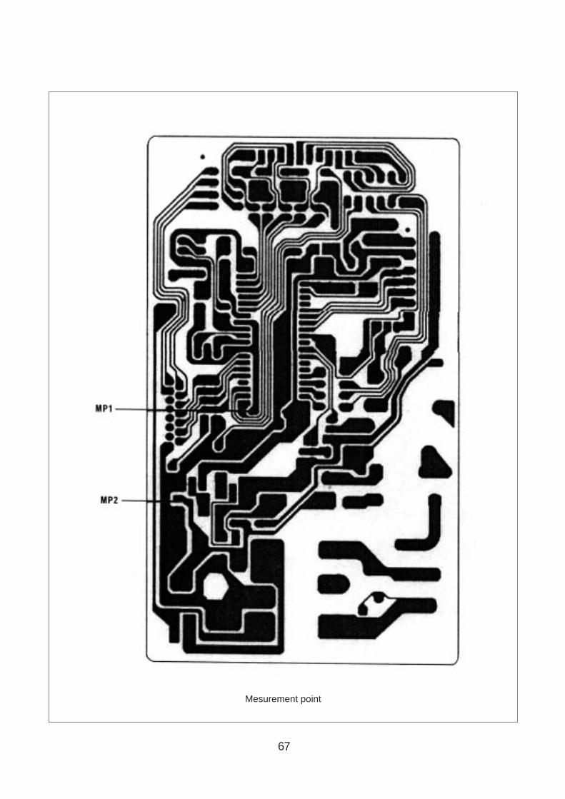
67
Mesurement point

68
3. When there is no microwave oscillation1) When touching START pad, oven lamp does not turn on.
Fan motor do not rotate, but cook indicator in display comes on. Cause : RELAY 2 does not operate. → refer to Circuit Diagram (point 3)- Check method
2) When touching START pad, oven lamp turns on.Fan motor and turntable rotate and cook indicator in display comes on. Cause : RELAY 1 does not operate. → refer to Circuit Diagram (point 2)- Check method
4. When there is no grill oscillation. Cause : RELAY 3 does not operate. → refer to Circuit Diagram (point 6)- Check method
5. When the door is opened during operation, the count down timer does not stop.
→ refer to Circuit Diagram (point 1)- Check method
6. When the digital clock does not operate properly.→ refer to Circuit Diagram (point 5)
If clock does not keep exact time, you must check resistor R15,16, zener diode ZD1.
POINTA BSTATE
RELAY 2 ON -5VDC GND
RELAY 2 OFF GND -12VDC
POINTA BSTATE
RELAY 1 ON -5VDC GND
RELAY 1 OFF GND -12VDC
POINTA BSTATE
RELAY 3 ON -5VDC GND
RELAY 3 OFF GND -12VDC
POINTA BSTATE
1) DOOR OPEN OPEN -5VDC
2) DOOR CLOSED CLOSE GND
CHECK NO HETHOD REMEDY
1 Check the stage(ON, OFF) of the door open monitor Replace door open monitor switch.switch by resistance measurement.
POINT WAVE FORM
A T: 20 ms(50Hz)
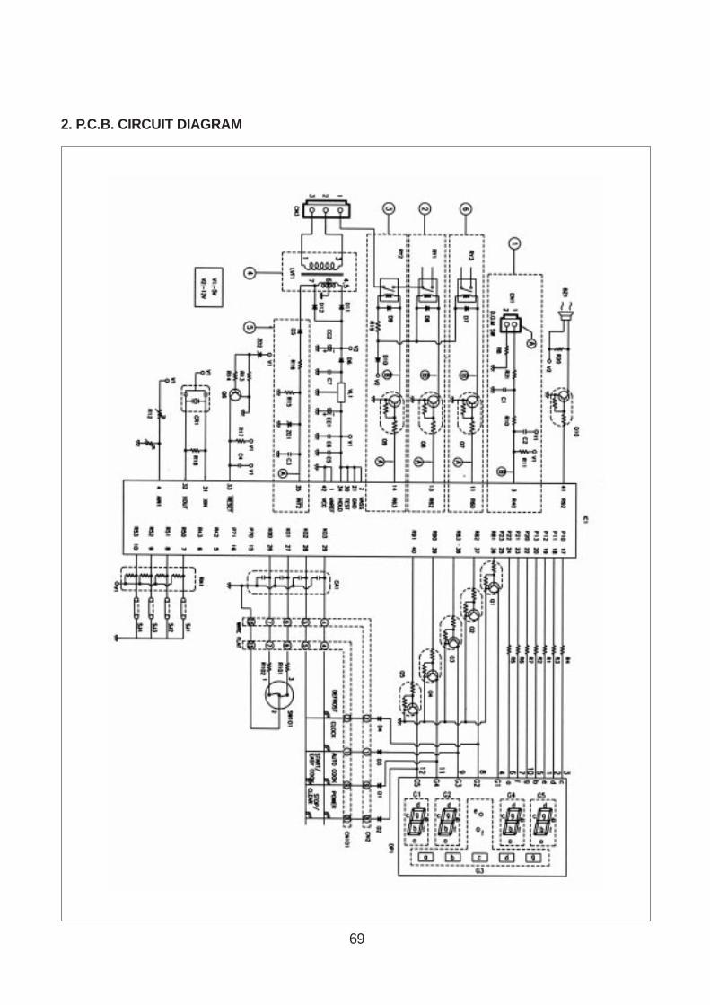
69
2. P.C.B. CIRCUIT DIAGRAM
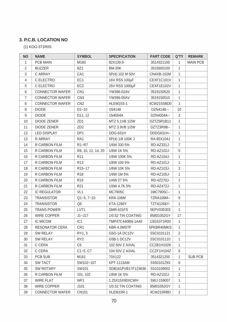
70
NO NAME SYMBOL SPECIFICATION PART CODE Q’TY REMARK
1 PCB MAIN M160 82X139.9 3514321100 1 MAIN PCB
2 BUZZER BZ1 BM-20K 3515600100 1
3 C ARRAY CA1 5P(4) 102 M 50V CN4XB-102M 1
4 C ELECTRO EC1 16V RSS 100µF CEXF1C101V 1
5 C ELECTRO EC2 25V RSS 1000µF CEXF1E102V 1
6 CONNECTOR WAFER CN1 YW396-02AV 3519150520 1
7 CONNECTOR WAFER CN3 YW396-05AV 3519150510 1
8 CONNECTOR WAFER CN2 HLEM15S-1 4CW215SBD0 1
8 DIODE D1~10 1N4148 DZN4148--- 10
9 DIODE D11, 12 1N4004A DZN4004A-- 2
10 DIODE ZENER ZD1 MTZ 5.1VB 1/2W DZTZ5R1B11 1
11 DIODE ZENER ZD2 MTZ 3.9VB 1/2W DZTZ3R9B-- 1
12 LED DISPLAY DP1 DDG-631H DDDG631H-- 1
13 R ARRAY RA1 5P(4) 1/8 100K J RA-85X104J 1
14 R CARBON FILM R1~R7 1/6W 330 5% RD-AZ331J- 7
15 R CARBON FILM R8, 10, 12, 14, 20 1/6W 1K 5% RD-AZ102J- 5
16 R CARBON FILM R11 1/6W 100K 5% RD-AZ104J- 1
17 R CARBON FILM R13 1/6W 100 5% RD-AZ101J- 1
18 R CARBON FILM R15~17 1/6W 10K 5% RD-AZ103J- 3
19 R CARBON FILM R18 1/6W 1M 5% RD-AZ105J- 1
20 R CARBON FILM R19 1/4W 27 5% RD-4Z270J- 1
21 R CARBON FILM R21 1/6W 4.7K 5% RD-AZ472J- 1
22 IC REGULATOR VL1 MC7905C 1MC7905C-- 1
23 TRANSISTOR Q1~5, 7~10 KRA-106M TZRA106M-- 9
24 TRANSISTOR Q6 KTA-1266Y TZTA1266Y- 1
25 TRANS POWER LVT1 DMR-631FS 5EPV035303 1
26 WIRE COPPER J1~J17 1/0.52 TIN COATING 85801052GY 17
27 IC MICOM IC1 TMP47C440BN-1A49 13GS371R00 1
28 RESONATOR CERA CR1 KBR-4.0MSTF 5PKBR40MKS 1
29 SW RELAY RY1, 3 G5G-1A DC12V 5SC0101121 2
30 SW RELAY RY2 G5B-1 DC12V 5SC0101110 1
31 C CERA C6 102 50V Z AXIAL CCZB1H102K 1
32 C CERA C1~5, C7 104 50V Z AXIAL CCZF1H104Z 6
33 PCB SUB M161 70X122 3514321200 1 SUB PCB
34 SW TACT SW102~107 KPT-1115AM 5S50101Z93 6
35 SW ROTARY SW101 SDB161PVB17F123636 5S10109002 1
36 R CARBON FILM 101, 102 1/6W 1K 5% RD-AZ102J- 2
37 WIRE FLAT WF1 1.25X15X90XCWH SWJ-159007 1
38 WIRE COPPER J101 1/0.52 TIN COATING 85801052GY 1
39 CONNECTOR WAFER CN101 HLEM15R-1 4CW215RBD 1
3. P.C.B. LOCATION NO(1) KOG-371R0S
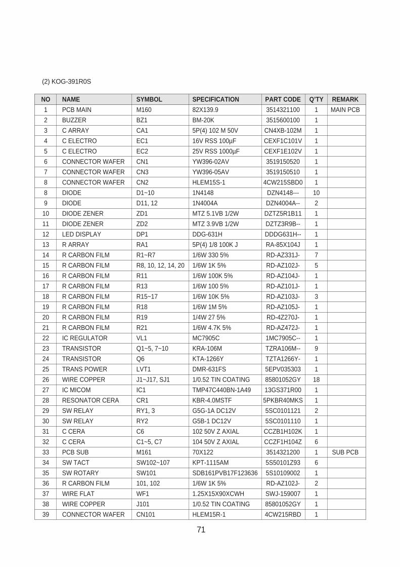
71
(2) KOG-391R0S
NO NAME SYMBOL SPECIFICATION PART CODE Q’TY REMARK
1 PCB MAIN M160 82X139.9 3514321100 1 MAIN PCB
2 BUZZER BZ1 BM-20K 3515600100 1
3 C ARRAY CA1 5P(4) 102 M 50V CN4XB-102M 1
4 C ELECTRO EC1 16V RSS 100µF CEXF1C101V 1
5 C ELECTRO EC2 25V RSS 1000µF CEXF1E102V 1
6 CONNECTOR WAFER CN1 YW396-02AV 3519150520 1
7 CONNECTOR WAFER CN3 YW396-05AV 3519150510 1
8 CONNECTOR WAFER CN2 HLEM15S-1 4CW215SBD0 1
8 DIODE D1~10 1N4148 DZN4148--- 10
9 DIODE D11, 12 1N4004A DZN4004A-- 2
10 DIODE ZENER ZD1 MTZ 5.1VB 1/2W DZTZ5R1B11 1
11 DIODE ZENER ZD2 MTZ 3.9VB 1/2W DZTZ3R9B-- 1
12 LED DISPLAY DP1 DDG-631H DDDG631H-- 1
13 R ARRAY RA1 5P(4) 1/8 100K J RA-85X104J 1
14 R CARBON FILM R1~R7 1/6W 330 5% RD-AZ331J- 7
15 R CARBON FILM R8, 10, 12, 14, 20 1/6W 1K 5% RD-AZ102J- 5
16 R CARBON FILM R11 1/6W 100K 5% RD-AZ104J- 1
17 R CARBON FILM R13 1/6W 100 5% RD-AZ101J- 1
18 R CARBON FILM R15~17 1/6W 10K 5% RD-AZ103J- 3
19 R CARBON FILM R18 1/6W 1M 5% RD-AZ105J- 1
20 R CARBON FILM R19 1/4W 27 5% RD-4Z270J- 1
21 R CARBON FILM R21 1/6W 4.7K 5% RD-AZ472J- 1
22 IC REGULATOR VL1 MC7905C 1MC7905C-- 1
23 TRANSISTOR Q1~5, 7~10 KRA-106M TZRA106M-- 9
24 TRANSISTOR Q6 KTA-1266Y TZTA1266Y- 1
25 TRANS POWER LVT1 DMR-631FS 5EPV035303 1
26 WIRE COPPER J1~J17, SJ1 1/0.52 TIN COATING 85801052GY 18
27 IC MICOM IC1 TMP47C440BN-1A49 13GS371R00 1
28 RESONATOR CERA CR1 KBR-4.0MSTF 5PKBR40MKS 1
29 SW RELAY RY1, 3 G5G-1A DC12V 5SC0101121 2
30 SW RELAY RY2 G5B-1 DC12V 5SC0101110 1
31 C CERA C6 102 50V Z AXIAL CCZB1H102K 1
32 C CERA C1~5, C7 104 50V Z AXIAL CCZF1H104Z 6
33 PCB SUB M161 70X122 3514321200 1 SUB PCB
34 SW TACT SW102~107 KPT-1115AM 5S50101Z93 6
35 SW ROTARY SW101 SDB161PVB17F123636 5S10109002 1
36 R CARBON FILM 101, 102 1/6W 1K 5% RD-AZ102J- 2
37 WIRE FLAT WF1 1.25X15X90XCWH SWJ-159007 1
38 WIRE COPPER J101 1/0.52 TIN COATING 85801052GY 1
39 CONNECTOR WAFER CN101 HLEM15R-1 4CW215RBD 1

72
PRINTED CIRCUIT BOARD <KOG-374R0S, KOG-375R0S>
1. CIRCUIT CHECK PROCEDURE
1. Low Voltage Transformer check• The low voltage transformer is located on the P.C.B.• Measuring condition: input voltage : 230V/Frequency : 50Hz
2. Voltage check• Key check point
• Check method
NO CHECK POINT REMARK
1 IC 1 PIN 2, 21, 30, 34 –5 VDC
2 IC 1 PIN 35
3 IC 1 PIN 31 OR 32
NOTE :Each measure point must be measured with GND points.
NOTE :1. Refer to Circuit Diagram (point 4).2. Secondary side voltage of the low voltage transformer changes in proportion to fluctuation of power source voltage.3. The allowable tolerance of the secondary voltage is within ± 5% of nominal voltage.
T
0V
–5V
T: 250 ns (4MHz)
0V
T–5V
Terminal Voltage
4-7
LOAD
AC 25.8 V
NO LOAD
AC 28.4 V
NO MEASURE POINT WAVE FORM REMEDY REMARK
1 MP1 DC -5V±0.25V Replace VL1, EC1 NO LOAD
2 MP2 DC -12V±2.0V Replace EC2, D6, D11, D12 NO LOAD
T:20ms(50Hz)
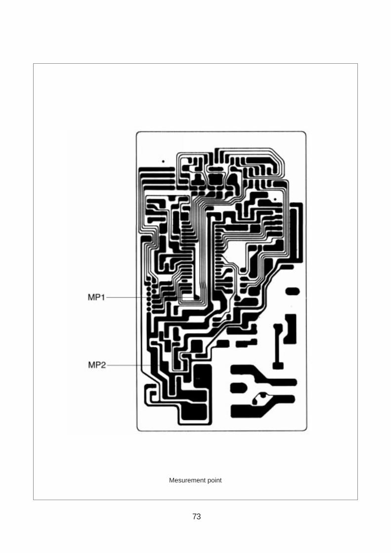
73
Mesurement point
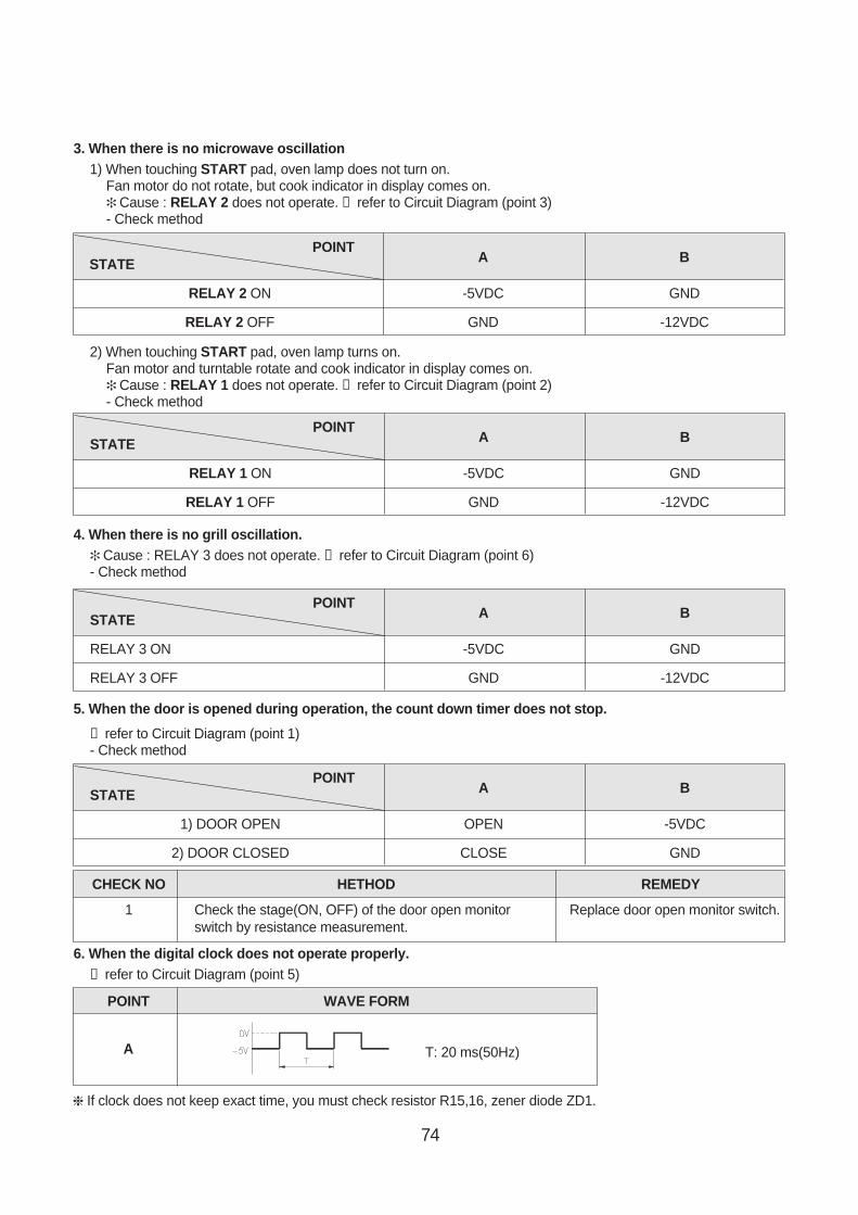
74
3. When there is no microwave oscillation1) When touching START pad, oven lamp does not turn on.
Fan motor do not rotate, but cook indicator in display comes on. Cause : RELAY 2 does not operate. → refer to Circuit Diagram (point 3)- Check method
2) When touching START pad, oven lamp turns on.Fan motor and turntable rotate and cook indicator in display comes on. Cause : RELAY 1 does not operate. → refer to Circuit Diagram (point 2)- Check method
4. When there is no grill oscillation. Cause : RELAY 3 does not operate. → refer to Circuit Diagram (point 6)- Check method
5. When the door is opened during operation, the count down timer does not stop.
→ refer to Circuit Diagram (point 1)- Check method
6. When the digital clock does not operate properly.→ refer to Circuit Diagram (point 5)
If clock does not keep exact time, you must check resistor R15,16, zener diode ZD1.
POINTA BSTATE
RELAY 2 ON -5VDC GND
RELAY 2 OFF GND -12VDC
POINTA BSTATE
RELAY 1 ON -5VDC GND
RELAY 1 OFF GND -12VDC
POINTA BSTATE
RELAY 3 ON -5VDC GND
RELAY 3 OFF GND -12VDC
POINTA BSTATE
1) DOOR OPEN OPEN -5VDC
2) DOOR CLOSED CLOSE GND
CHECK NO HETHOD REMEDY
1 Check the stage(ON, OFF) of the door open monitor Replace door open monitor switch.switch by resistance measurement.
POINT WAVE FORM
A T: 20 ms(50Hz)
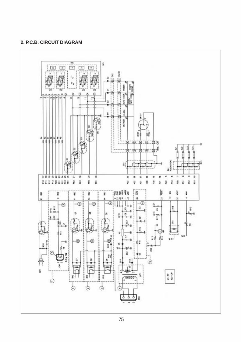
75
2. P.C.B. CIRCUIT DIAGRAM
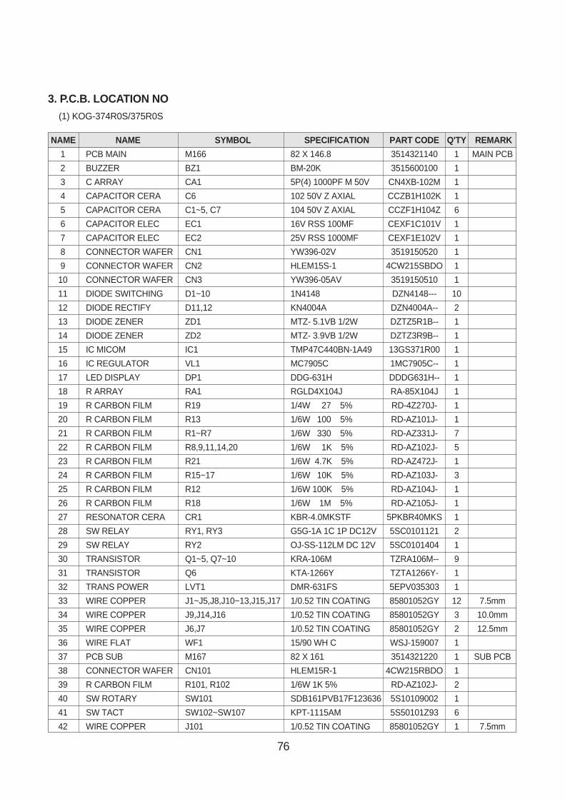
76
NAME NAME SYMBOL SPECIFICATION PART CODE Q'TY REMARK
1 PCB MAIN M166 82 X 146.8 3514321140 1 MAIN PCB
2 BUZZER BZ1 BM-20K 3515600100 1
3 C ARRAY CA1 5P(4) 1000PF M 50V CN4XB-102M 1
4 CAPACITOR CERA C6 102 50V Z AXIAL CCZB1H102K 1
5 CAPACITOR CERA C1~5, C7 104 50V Z AXIAL CCZF1H104Z 6
6 CAPACITOR ELEC EC1 16V RSS 100MF CEXF1C101V 1
7 CAPACITOR ELEC EC2 25V RSS 1000MF CEXF1E102V 1
8 CONNECTOR WAFER CN1 YW396-02V 3519150520 1
9 CONNECTOR WAFER CN2 HLEM15S-1 4CW215SBDO 1
10 CONNECTOR WAFER CN3 YW396-05AV 3519150510 1
11 DIODE SWITCHING D1~10 1N4148 DZN4148--- 10
12 DIODE RECTIFY D11,12 KN4004A DZN4004A-- 2
13 DIODE ZENER ZD1 MTZ- 5.1VB 1/2W DZTZ5R1B-- 1
14 DIODE ZENER ZD2 MTZ- 3.9VB 1/2W DZTZ3R9B-- 1
15 IC MICOM IC1 TMP47C440BN-1A49 13GS371R00 1
16 IC REGULATOR VL1 MC7905C 1MC7905C-- 1
17 LED DISPLAY DP1 DDG-631H DDDG631H-- 1
18 R ARRAY RA1 RGLD4X104J RA-85X104J 1
19 R CARBON FILM R19 1/4W 27 5% RD-4Z270J- 1
20 R CARBON FILM R13 1/6W 100 5% RD-AZ101J- 1
21 R CARBON FILM R1~R7 1/6W 330 5% RD-AZ331J- 7
22 R CARBON FILM R8,9,11,14,20 1/6W 1K 5% RD-AZ102J- 5
23 R CARBON FILM R21 1/6W 4.7K 5% RD-AZ472J- 1
24 R CARBON FILM R15~17 1/6W 10K 5% RD-AZ103J- 3
25 R CARBON FILM R12 1/6W 100K 5% RD-AZ104J- 1
26 R CARBON FILM R18 1/6W 1M 5% RD-AZ105J- 1
27 RESONATOR CERA CR1 KBR-4.0MKSTF 5PKBR40MKS 1
28 SW RELAY RY1, RY3 G5G-1A 1C 1P DC12V 5SC0101121 2
29 SW RELAY RY2 OJ-SS-112LM DC 12V 5SC0101404 1
30 TRANSISTOR Q1~5, Q7~10 KRA-106M TZRA106M-- 9
31 TRANSISTOR Q6 KTA-1266Y TZTA1266Y- 1
32 TRANS POWER LVT1 DMR-631FS 5EPV035303 1
33 WIRE COPPER J1~J5,J8,J10~13,J15,J17 1/0.52 TIN COATING 85801052GY 12 7.5mm
34 WIRE COPPER J9,J14,J16 1/0.52 TIN COATING 85801052GY 3 10.0mm
35 WIRE COPPER J6,J7 1/0.52 TIN COATING 85801052GY 2 12.5mm
36 WIRE FLAT WF1 15/90 WH C WSJ-159007 1
37 PCB SUB M167 82 X 161 3514321220 1 SUB PCB
38 CONNECTOR WAFER CN101 HLEM15R-1 4CW215RBDO 1
39 R CARBON FILM R101, R102 1/6W 1K 5% RD-AZ102J- 2
40 SW ROTARY SW101 SDB161PVB17F123636 5S10109002 1
41 SW TACT SW102~SW107 KPT-1115AM 5S50101Z93 6
42 WIRE COPPER J101 1/0.52 TIN COATING 85801052GY 1 7.5mm
3. P.C.B. LOCATION NO(1) KOG-374R0S/375R0S
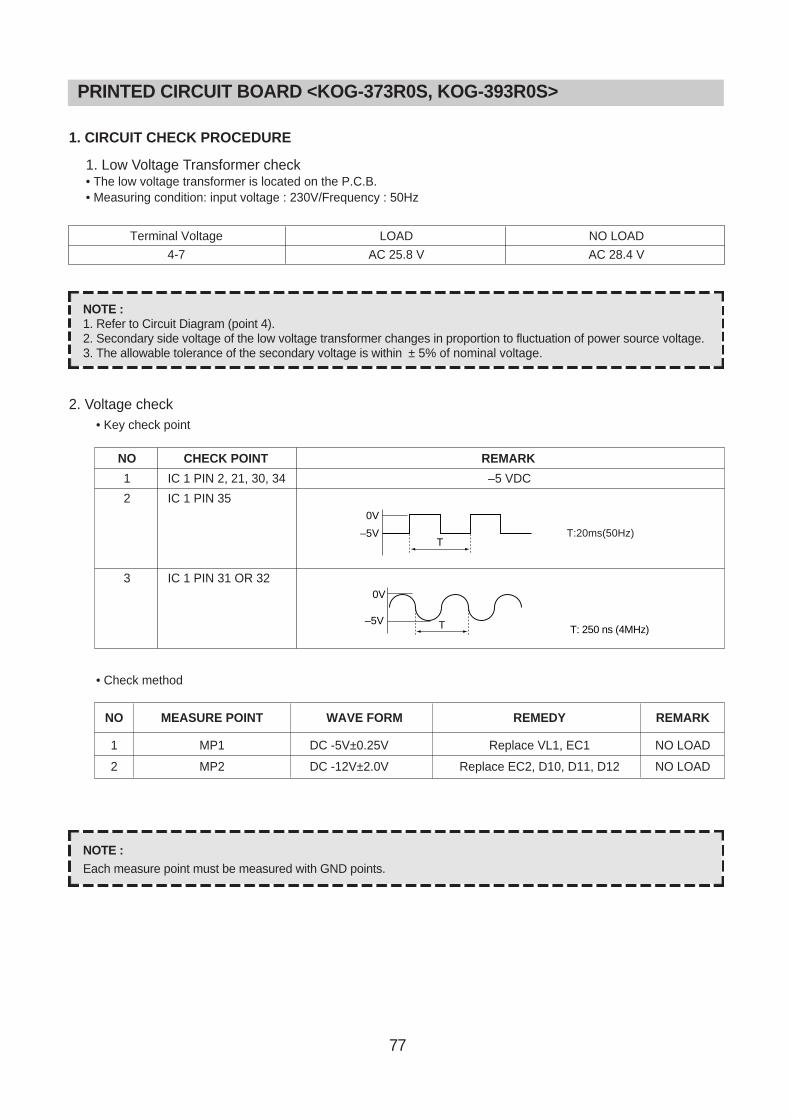
77
PRINTED CIRCUIT BOARD <KOG-373R0S, KOG-393R0S>
1. CIRCUIT CHECK PROCEDURE
1. Low Voltage Transformer check• The low voltage transformer is located on the P.C.B.• Measuring condition: input voltage : 230V/Frequency : 50Hz
2. Voltage check• Key check point
• Check method
NO CHECK POINT REMARK
1 IC 1 PIN 2, 21, 30, 34 –5 VDC
2 IC 1 PIN 35
3 IC 1 PIN 31 OR 32
NOTE :Each measure point must be measured with GND points.
NOTE :1. Refer to Circuit Diagram (point 4).2. Secondary side voltage of the low voltage transformer changes in proportion to fluctuation of power source voltage.3. The allowable tolerance of the secondary voltage is within ± 5% of nominal voltage.
T
0V
–5V
T: 250 ns (4MHz)
0V
T–5V
Terminal Voltage
4-7
LOAD
AC 25.8 V
NO LOAD
AC 28.4 V
NO MEASURE POINT WAVE FORM REMEDY REMARK
1 MP1 DC -5V±0.25V Replace VL1, EC1 NO LOAD
2 MP2 DC -12V±2.0V Replace EC2, D10, D11, D12 NO LOAD
T:20ms(50Hz)
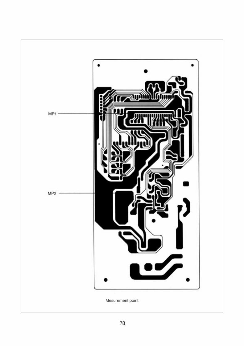
78
Mesurement point

79
3. When there is no microwave oscillation1) When touching START pad, oven lamp does not turn on.
Fan motor do not rotate, but cook indicator in display comes on. Cause : RELAY 2 does not operate. → refer to Circuit Diagram (point 3)- Check method
2) When touching START pad, oven lamp turns on.Fan motor and turntable rotate and cook indicator in display comes on. Cause : RELAY 1 does not operate. → refer to Circuit Diagram (point 2)- Check method
4. When there is no grill oscillation. Cause : RELAY 3 does not operate. → refer to Circuit Diagram (point 6)- Check method
5. When the door is opened during operation, the count down timer does not stop.
→ refer to Circuit Diagram (point 1)- Check method
6. When the digital clock does not operate properly.→ refer to Circuit Diagram (point 5)
If clock does not keep exact time, you must check resistor R15,16, zener diode ZD1.
POINTA BSTATE
RELAY 2 ON -5VDC GND
RELAY 2 OFF GND -12VDC
POINTA BSTATE
RELAY 1 ON -5VDC GND
RELAY 1 OFF GND -12VDC
POINTA BSTATE
RELAY 3 ON -5VDC GND
RELAY 3 OFF GND -12VDC
POINTA BSTATE
1) DOOR OPEN OPEN -5VDC
2) DOOR CLOSED CLOSE GND
CHECK NO HETHOD REMEDY
1 Check the stage(ON, OFF) of the door open monitor Replace door open monitor switch.switch by resistance measurement.
POINT WAVE FORM
A T: 20 ms(50Hz)
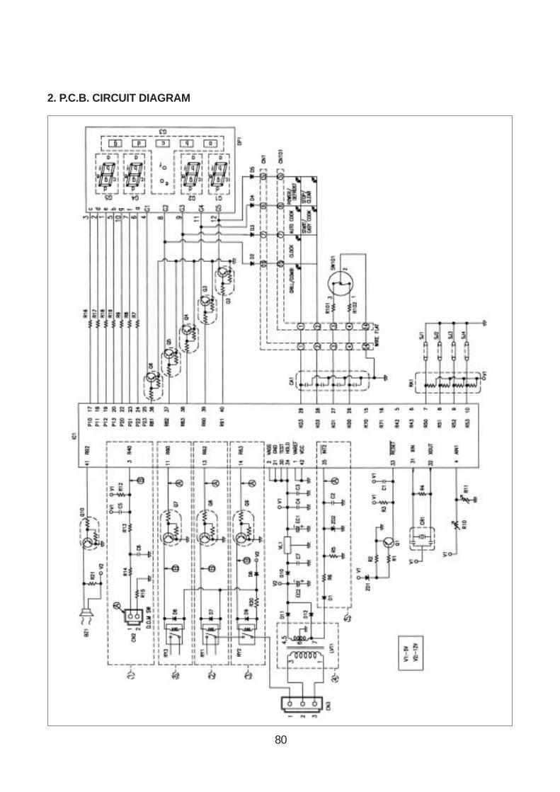
80
2. P.C.B. CIRCUIT DIAGRAM
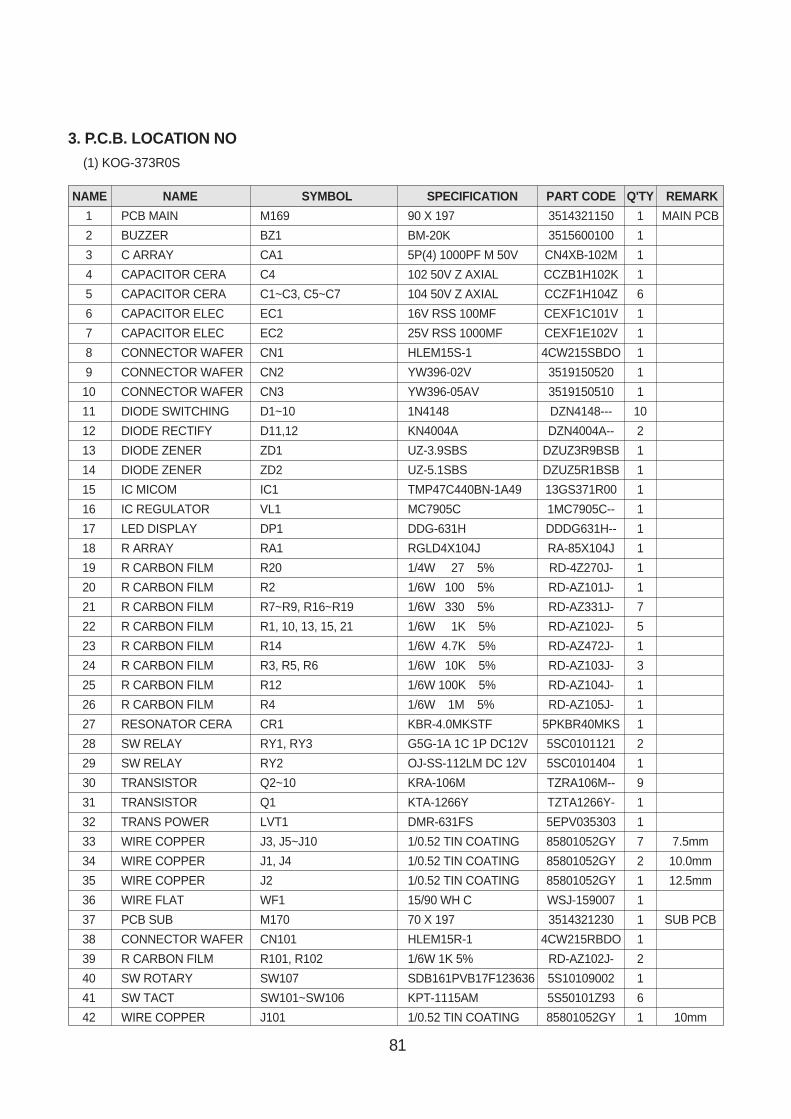
81
NAME NAME SYMBOL SPECIFICATION PART CODE Q'TY REMARK
1 PCB MAIN M169 90 X 197 3514321150 1 MAIN PCB
2 BUZZER BZ1 BM-20K 3515600100 1
3 C ARRAY CA1 5P(4) 1000PF M 50V CN4XB-102M 1
4 CAPACITOR CERA C4 102 50V Z AXIAL CCZB1H102K 1
5 CAPACITOR CERA C1~C3, C5~C7 104 50V Z AXIAL CCZF1H104Z 6
6 CAPACITOR ELEC EC1 16V RSS 100MF CEXF1C101V 1
7 CAPACITOR ELEC EC2 25V RSS 1000MF CEXF1E102V 1
8 CONNECTOR WAFER CN1 HLEM15S-1 4CW215SBDO 1
9 CONNECTOR WAFER CN2 YW396-02V 3519150520 1
10 CONNECTOR WAFER CN3 YW396-05AV 3519150510 1
11 DIODE SWITCHING D1~10 1N4148 DZN4148--- 10
12 DIODE RECTIFY D11,12 KN4004A DZN4004A-- 2
13 DIODE ZENER ZD1 UZ-3.9SBS DZUZ3R9BSB 1
14 DIODE ZENER ZD2 UZ-5.1SBS DZUZ5R1BSB 1
15 IC MICOM IC1 TMP47C440BN-1A49 13GS371R00 1
16 IC REGULATOR VL1 MC7905C 1MC7905C-- 1
17 LED DISPLAY DP1 DDG-631H DDDG631H-- 1
18 R ARRAY RA1 RGLD4X104J RA-85X104J 1
19 R CARBON FILM R20 1/4W 27 5% RD-4Z270J- 1
20 R CARBON FILM R2 1/6W 100 5% RD-AZ101J- 1
21 R CARBON FILM R7~R9, R16~R19 1/6W 330 5% RD-AZ331J- 7
22 R CARBON FILM R1, 10, 13, 15, 21 1/6W 1K 5% RD-AZ102J- 5
23 R CARBON FILM R14 1/6W 4.7K 5% RD-AZ472J- 1
24 R CARBON FILM R3, R5, R6 1/6W 10K 5% RD-AZ103J- 3
25 R CARBON FILM R12 1/6W 100K 5% RD-AZ104J- 1
26 R CARBON FILM R4 1/6W 1M 5% RD-AZ105J- 1
27 RESONATOR CERA CR1 KBR-4.0MKSTF 5PKBR40MKS 1
28 SW RELAY RY1, RY3 G5G-1A 1C 1P DC12V 5SC0101121 2
29 SW RELAY RY2 OJ-SS-112LM DC 12V 5SC0101404 1
30 TRANSISTOR Q2~10 KRA-106M TZRA106M-- 9
31 TRANSISTOR Q1 KTA-1266Y TZTA1266Y- 1
32 TRANS POWER LVT1 DMR-631FS 5EPV035303 1
33 WIRE COPPER J3, J5~J10 1/0.52 TIN COATING 85801052GY 7 7.5mm
34 WIRE COPPER J1, J4 1/0.52 TIN COATING 85801052GY 2 10.0mm
35 WIRE COPPER J2 1/0.52 TIN COATING 85801052GY 1 12.5mm
36 WIRE FLAT WF1 15/90 WH C WSJ-159007 1
37 PCB SUB M170 70 X 197 3514321230 1 SUB PCB
38 CONNECTOR WAFER CN101 HLEM15R-1 4CW215RBDO 1
39 R CARBON FILM R101, R102 1/6W 1K 5% RD-AZ102J- 2
40 SW ROTARY SW107 SDB161PVB17F123636 5S10109002 1
41 SW TACT SW101~SW106 KPT-1115AM 5S50101Z93 6
42 WIRE COPPER J101 1/0.52 TIN COATING 85801052GY 1 10mm
3. P.C.B. LOCATION NO(1) KOG-373R0S
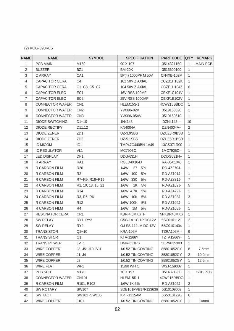
82
NAME NAME SYMBOL SPECIFICATION PART CODE Q'TY REMARK
1 PCB MAIN M169 90 X 197 3514321150 1 MAIN PCB
2 BUZZER BZ1 BM-20K 3515600100 1
3 C ARRAY CA1 5P(4) 1000PF M 50V CN4XB-102M 1
4 CAPACITOR CERA C4 102 50V Z AXIAL CCZB1H102K 1
5 CAPACITOR CERA C1~C3, C5~C7 104 50V Z AXIAL CCZF1H104Z 6
6 CAPACITOR ELEC EC1 16V RSS 100MF CEXF1C101V 1
7 CAPACITOR ELEC EC2 25V RSS 1000MF CEXF1E102V 1
8 CONNECTOR WAFER CN1 HLEM15S-1 4CW215SBDO 1
9 CONNECTOR WAFER CN2 YW396-02V 3519150520 1
10 CONNECTOR WAFER CN3 YW396-05AV 3519150510 1
11 DIODE SWITCHING D1~10 1N4148 DZN4148--- 10
12 DIODE RECTIFY D11,12 KN4004A DZN4004A-- 2
13 DIODE ZENER ZD1 UZ-3.9SBS DZUZ3R9BSB 1
14 DIODE ZENER ZD2 UZ-5.1SBS DZUZ5R1BSB 1
15 IC MICOM IC1 TMP47C440BN-1A49 13GS371R00 1
16 IC REGULATOR VL1 MC7905C 1MC7905C-- 1
17 LED DISPLAY DP1 DDG-631H DDDG631H-- 1
18 R ARRAY RA1 RGLD4X104J RA-85X104J 1
19 R CARBON FILM R20 1/4W 27 5% RD-4Z270J- 1
20 R CARBON FILM R2 1/6W 100 5% RD-AZ101J- 1
21 R CARBON FILM R7~R9, R16~R19 1/6W 330 5% RD-AZ331J- 7
22 R CARBON FILM R1, 10, 13, 15, 21 1/6W 1K 5% RD-AZ102J- 5
23 R CARBON FILM R14 1/6W 4.7K 5% RD-AZ472J- 1
24 R CARBON FILM R3, R5, R6 1/6W 10K 5% RD-AZ103J- 3
25 R CARBON FILM R12 1/6W 100K 5% RD-AZ104J- 1
26 R CARBON FILM R4 1/6W 1M 5% RD-AZ105J- 1
27 RESONATOR CERA CR1 KBR-4.0MKSTF 5PKBR40MKS 1
28 SW RELAY RY1, RY3 G5G-1A 1C 1P DC12V 5SC0101121 2
29 SW RELAY RY2 OJ-SS-112LM DC 12V 5SC0101404 1
30 TRANSISTOR Q2~10 KRA-106M TZRA106M-- 9
31 TRANSISTOR Q1 KTA-1266Y TZTA1266Y- 1
32 TRANS POWER LVT1 DMR-631FS 5EPV035303 1
33 WIRE COPPER J3, J5~J10, SJ1 1/0.52 TIN COATING 85801052GY 8 7.5mm
34 WIRE COPPER J1, J4 1/0.52 TIN COATING 85801052GY 2 10.0mm
35 WIRE COPPER J2 1/0.52 TIN COATING 85801052GY 1 12.5mm
36 WIRE FLAT WF1 15/90 WH C WSJ-159007 1
37 PCB SUB M170 70 X 197 3514321230 1 SUB PCB
38 CONNECTOR WAFER CN101 HLEM15R-1 4CW215RBDO 1
39 R CARBON FILM R101, R102 1/6W 1K 5% RD-AZ102J- 2
40 SW ROTARY SW107 SDB161PVB17F123636 5S10109002 1
41 SW TACT SW101~SW106 KPT-1115AM 5S50101Z93 6
42 WIRE COPPER J101 1/0.52 TIN COATING 85801052GY 1 10mm
(2) KOG-393R0S
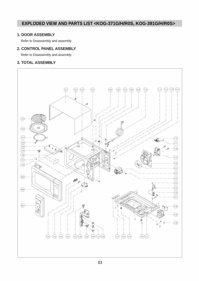
83
1. DOOR ASSEMBLYRefer to Disassembly and assembly
2. CONTROL PANEL ASSEMBL YRefer to Disassembly and assembly
3. TOTAL ASSEMBL Y
EXPLODED VIEW AND PARTS LIST <KOG-371G/H/R0S, KOG-391G/H/R0S>

84
REF NO PART CODE PART NAME DESCRIPTION Q'TY
A00 3511710300 DOOR AS KOG-63150S 1
B00 3516721610 CONTROL PANEL AS KOG-371G0S 1
3516721600 CONTROL PANEL AS KOG-371H0S 1
B01 3516721630 CONTRON PANEL AS KOG-371R0S 1
F01 3510801310 CABINET SECC 1
F02 7112401011 SPECIAL SCREW T1 TRS 4X10 MFZN 3
F03 3516109610 CAVITY AS CAVITY AS 1
F04 7392500008 NUT HEX 6N-2-5 2
F05 7122401211 SCREW TAPPING T2S TRS 4X12 MFZN 1
F06 3518904500 THERMOSTAT OFF : 100 ON : 90 HN #187 1
F07 7121300611 SCREW TAPPING T2S PAN 3X6 MFZN 1
F08 7122401211 SCREW TAPPING T2S TRS 4X12 MFZN 1
F09 7112401011 SCREW TAPPING T1 TRS 4X10 MFZN 2
F10 35113A5QJ5 CORD POWER AS 3X1.5 80X80 120-RTML 1.4M 1
F12 7112401011 SCREW TAPPING T1 TRS 4X10 MFZN 1
F13 7122401211 SCREW TAPPING T2S TRS 4X12 MFZN 1
F14 7112401011 SCREW TAPPING T1 TRS 4X10 MFZN 1
F15 7S627W50X1 NUT HEX NUT FLANGE M5X0.8P MFZN 1
F16 4414A25110 FUSE 250V 15A 65TS 1
4414A25100 FUSE 250V 15A MDA15 1
F17 3518606100 NOISE-FILTER DWLF-M13 1
F18 7121402511 SCREW TAPPING T2S PAN 4X25 MFZN 2
F19 3963513100 MOTOR SHADED POLE 230V 17W OEM-10DWC2-A07 1
3963512310 MOTOR SHADED POLE 230V 20W MW10CA-M02 1
F20 3512517000 GUIDE WIND PP 1
F21 3511800300 FAN PP+30% GLASS 1
F22 3518002200 MAGNETRON 2M218H(MF) 1
F23 3516004000 SPECIAL SCREW T2 BOLT FLANGE 5X12 DACRO 1
F24 7S422X4081 SPECIAL SCREW TT2 TRS 4X8 SE MFZN 1
F25 3513003200 HOLDER HV CAPACITOR SECC 1
F26 3518302200 CAPACITOR HV 2100VAC 0.98µF #187 1
F27 3518400400 DIODE HV HVR-1X-3AB 12KV #187 1
F28 3518701100 FUSE HV 5KV 0.55A HV-41A55-02 1
F29 3518113700 TRANS HV DY-N80S0-63T 1
F30 3516003700 SPECIAL SCREW TT3 HEX 4X8 FLG MFZN 4
F31 3510311700 BASE SBHG 1
F32 7112401011 SCREW TAPPING T1 TRS 4X10 MFZN 5
(1) KOG-371G0S/371H0S/371R0S

85
REF NO PART CODE PART NAME DESCRIPTION Q'TY
F33 3512100900 FOOT PP DASF-130 2
F34 7S422X4081 SPECIAL SCREW TT2 TRS 4X8 MFZN 1
F35 3515201101 STOPPER HINGE *U SCP-1 1
F36 4415A17352 SW MICRO VP-533A-OF SPNO #187 200G 1
F37 4415A66910 SW MICRO VP-531A-OF/SZM-V16-FA-61 1
F38 4415A17352 SW MICRO VP-533A-OF SPNO #187 200G 2
F39 3513702600 LEVER LOCK POM 1
F40 3513811700 LOCK POM 1
F41 3513601600 LAMP BL 240V 25W T25 C7A H187 1
F42 7112401011 SCREW TAPPING T2 TRS 4X10 MFZN 1
F43 3966310100 MOTOR SYNCRO 220V 2.5W GM-16-24FD12 1
3966310110 MOTOR SYNCRO 220V 2.5W M2LJ49ZT52 1
F44 3518905300 THERMOSTAT OFF: 75 ON: 65 H #187 NB 1
F45 3513003400 HOLDER THERMOSTAT PBT 1
F46 7272400811 SCREW TAPTITE TT3 TRS 4X8 MFZN 1
F47 4078502031 BUTTON LOCKING PP HONAM A353 2
F48 3511405100 COVER WAVE GUIDE MICA 1
F49 3517400620 COUPLER XAREC 1
F50 3514700710 ROLLER TEFLON 3
F51 3512517300 GUIDE ROLLER PP 5113MF6 A353B 1
3512517500 GUIDE ROLLER AS KOR-63150S 1
F52 3517203600 TRAY GLASS 1
F53 3517206900 TRAY RACK AS KOG-37150S 110MM 1
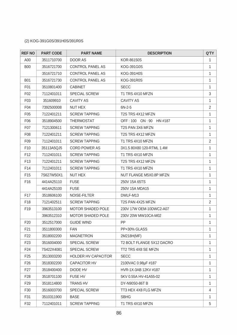
86
REF NO PART CODE PART NAME DESCRIPTION Q'TY
A00 3511710700 DOOR AS KOR-86150S 1
B00 3516721700 CONTROL PANEL AS KOG-391G0S 1
3516721710 CONTROL PANEL AS KOG-391H0S 1
B01 3516721730 CONTROL PANEL AS KOG-391R0S 1
F01 3510801400 CABINET SECC 1
F02 7112401011 SPECIAL SCREW T1 TRS 4X10 MFZN 3
F03 351609910 CAVITY AS CAVITY AS 1
F04 7392500008 NUT HEX 6N-2-5 2
F05 7122401211 SCREW TAPPING T2S TRS 4X12 MFZN 1
F06 3518904500 THERMOSTAT OFF : 100 ON : 90 HN #187 1
F07 7121300611 SCREW TAPPING T2S PAN 3X6 MFZN 1
F08 7122401211 SCREW TAPPING T2S TRS 4X12 MFZN 1
F09 7112401011 SCREW TAPPING T1 TRS 4X10 MFZN 2
F10 35113A5QJ5 CORD POWER AS 3X1.5 80X80 120-RTML 1.4M 1
F12 7112401011 SCREW TAPPING T1 TRS 4X10 MFZN 1
F13 7122401211 SCREW TAPPING T2S TRS 4X12 MFZN 1
F14 7112401011 SCREW TAPPING T1 TRS 4X10 MFZN 1
F15 7S627W50X1 NUT HEX NUT FLANGE M5X0.8P MFZN 1
F16 4414A25110 FUSE 250V 15A 65TS 1
4414A25100 FUSE 250V 15A MDA15 1
F17 3518606100 NOISE-FILTER DWLF-M13 1
F18 7121402511 SCREW TAPPING T2S PAN 4X25 MFZN 2
F19 3963513100 MOTOR SHADED POLE 230V 17W OEM-10DWC2-A07 1
3963512310 MOTOR SHADED POLE 230V 20W MW10CA-M02 1
F20 3512517000 GUIDE WIND PP 1
F21 3511800300 FAN PP+30% GLASS 1
F22 3518002200 MAGNETRON 2M218H(MF) 1
F23 3516004000 SPECIAL SCREW T2 BOLT FLANGE 5X12 DACRO 1
F24 7S422X4081 SPECIAL SCREW TT2 TRS 4X8 SE MFZN 1
F25 3513003200 HOLDER HV CAPACITOR SECC 1
F26 3518302200 CAPACITOR HV 2100VAC 0.98µF #187 1
F27 3518400400 DIODE HV HVR-1X-3AB 12KV #187 1
F28 3518701100 FUSE HV 5KV 0.55A HV-41A55-02 1
F29 3518114800 TRANS HV DY-N90S0-86T B 1
F30 3516003700 SPECIAL SCREW TT3 HEX 4X8 FLG MFZN 4
F31 3510311900 BASE SBHG 1
F32 7112401011 SCREW TAPPING T1 TRS 4X10 MFZN 5
(2) KOG-391G0S/391H0S/391R0S
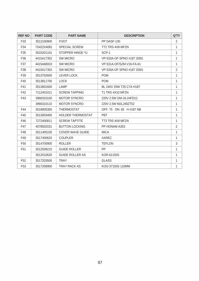
87
REF NO PART CODE PART NAME DESCRIPTION Q'TY
F33 3512100900 FOOT PP DASF-130 2
F34 7S422X4081 SPECIAL SCREW TT2 TRS 4X8 MFZN 1
F35 3515201101 STOPPER HINGE *U SCP-1 1
F36 4415A17352 SW MICRO VP-533A-OF SPNO #187 200G 1
F37 4415A66910 SW MICRO VP-531A-OF/SZM-V16-FA-61 1
F38 4415A17352 SW MICRO VP-533A-OF SPNO #187 200G 2
F39 3513702600 LEVER LOCK POM 1
F40 3513811700 LOCK POM 1
F41 3513601600 LAMP BL 240V 25W T25 C7A H187 1
F42 7112401011 SCREW TAPPING T1 TRS 4X10 MFZN 1
F43 3966310100 MOTOR SYNCRO 220V 2.5W GM-16-24FD12 1
3966310110 MOTOR SYNCRO 220V 2.5W M2LJ49ZT52 1
F44 3518905300 THERMOSTAT OFF: 75 ON: 65 H #187 NB 1
F45 3513003400 HOLDER THERMOSTAT PBT 1
F46 7272400811 SCREW TAPTITE TT3 TRS 4X8 MFZN 1
F47 4078502031 BUTTON LOCKING PP HONAM A353 2
F48 3511405100 COVER WAVE GUIDE MICA 1
F49 3517400620 COUPLER XAREC 1
F50 3514700900 ROLLER TEFLON 3
F51 3512509210 GUIDE ROLLER PP 1
3512510620 GUIDE ROLLER AS KOR-61150S 1
F52 3517203500 TRAY GLASS 1
F53 3517206900 TRAY RACK AS KOG-37150S 110MM 1
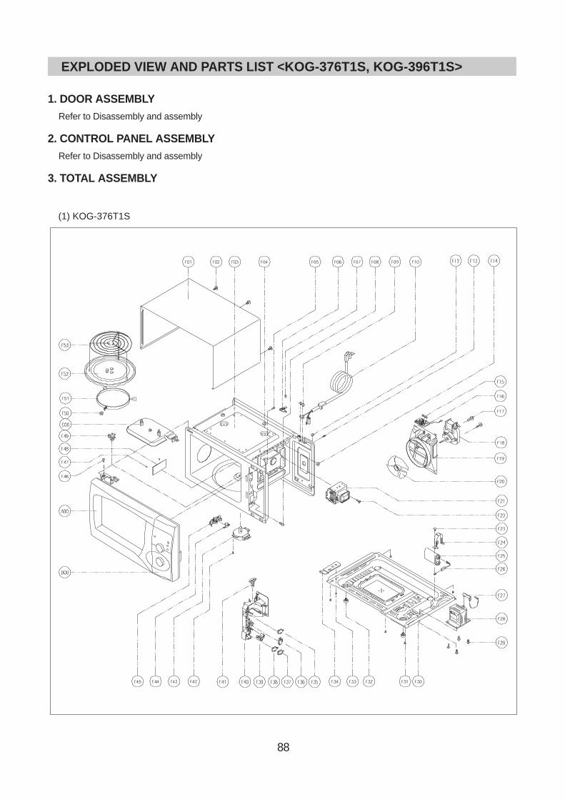
88
1. DOOR ASSEMBLYRefer to Disassembly and assembly
2. CONTROL PANEL ASSEMBL YRefer to Disassembly and assembly
3. TOTAL ASSEMBL Y
(1) KOG-376T1S
EXPLODED VIEW AND PARTS LIST <KOG-376T1S, KOG-396T1S>
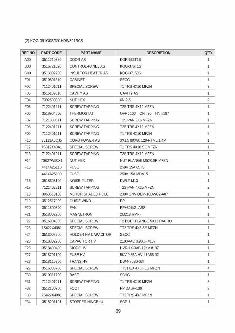
89
REF NO PART CODE PART NAME DESCRIPTION Q'TY
A00 3511710380 DOOR AS KOR-636T1S 1
B00 3516721620 CONTROL-PANEL AS KOG-376T1S 1
C00 3513302700 INSULTOR HEATER AS KOG-37150S 1
F01 3510801310 CABINET SECC 1
F02 7112401011 SPECIAL SCREW T1 TRS 4X10 MFZN 3
F03 3516109610 CAVITY AS CAVITY AS 1
F04 7392500008 NUT HEX 6N-2-5 2
F05 7122401211 SCREW TAPPING T2S TRS 4X12 MFZN 1
F06 3518904500 THERMOSTAT OFF : 100 ON : 90 HN #187 1
F07 7121300611 SCREW TAPPING T2S PAN 3X6 MFZN 1
F08 7122401211 SCREW TAPPING T2S TRS 4X12 MFZN 1
F09 7112401011 SCREW TAPPING T1 TRS 4X10 MFZN 2
F10 35113A5QJ5 CORD POWER AS 3X1.5 80X80 120-RTML 1.4M 1
F12 7S312X40A1 SPECIAL SCREW T1 TRS 4X10 SE MFZN 1
F13 7122401211 SCREW TAPPING T2S TRS 4X12 MFZN 1
F14 7S627W50X1 NUT HEX NUT FLANGE M5X0.8P MFZN 1
F15 4414A25110 FUSE 250V 15A 65TS 1
4414A25100 FUSE 250V 15A MDA15 1
F16 3518606100 NOISE-FILTER DWLF-M13 1
F17 7121402511 SCREW TAPPING T2S PAN 4X25 MFZN 2
F18 3963513100 MOTOR SHADED POLE 230V 17W OEM-10DWC2-A07 1
F19 3512517000 GUIDE WIND PP 1
F20 3511800300 FAN PP+30%GLASS 1
F21 3518002200 MAGNETRON 2M218H(MF) 1
F22 3516004000 SPECIAL SCREW T2 BOLT FLANGE 5X12 DACRO 1
F23 7S422X4081 SPECIAL SCREW TT2 TRS 4X8 SE MFZN 1
F24 3513003200 HOLDER HV CAPACITOR SECC 1
F25 3518302200 CAPACITOR HV 2100VAC 0.98µF #187 1
F26 3518400400 DIODE HV HVR-1X-3AB 12KV #187 1
F27 3518701100 FUSE HV 5KV 0.55A HV-41A55-02 1
F28 3518115300 TRANS HV DW-N80S0-63T 1
F29 3516003700 SPECIAL SCREW TT3 HEX 4X8 FLG MFZN 4
F30 3510311700 BASE SBHG 1
F31 7112401011 SCREW TAPPING T1 TRS 4X10 MFZN 5
F32 3512100900 FOOT PP DASF-130 2
F33 7S422X4081 SPECIAL SCREW TT2 TRS 4X8 MFZN 1
F34 3515201101 STOPPER HINGE *U SCP-1 1
(2) KOG-391G0S/391H0S/391R0S
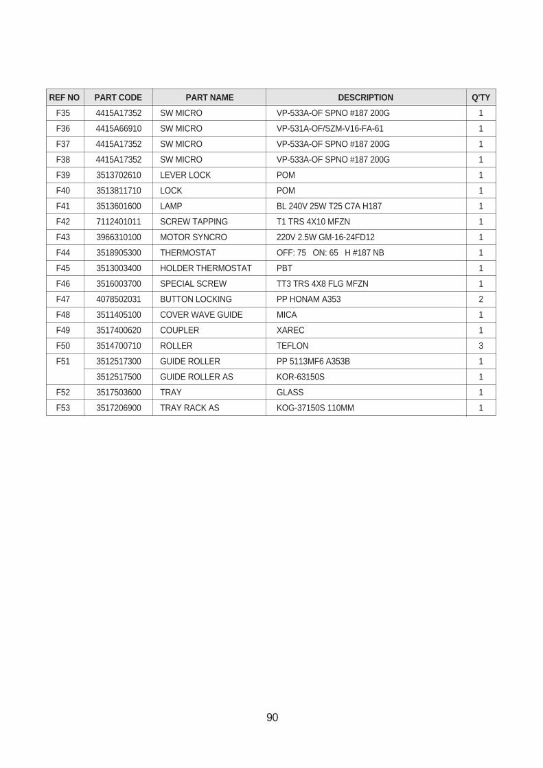
90
REF NO PART CODE PART NAME DESCRIPTION Q'TY
F35 4415A17352 SW MICRO VP-533A-OF SPNO #187 200G 1
F36 4415A66910 SW MICRO VP-531A-OF/SZM-V16-FA-61 1
F37 4415A17352 SW MICRO VP-533A-OF SPNO #187 200G 1
F38 4415A17352 SW MICRO VP-533A-OF SPNO #187 200G 1
F39 3513702610 LEVER LOCK POM 1
F40 3513811710 LOCK POM 1
F41 3513601600 LAMP BL 240V 25W T25 C7A H187 1
F42 7112401011 SCREW TAPPING T1 TRS 4X10 MFZN 1
F43 3966310100 MOTOR SYNCRO 220V 2.5W GM-16-24FD12 1
F44 3518905300 THERMOSTAT OFF: 75 ON: 65 H #187 NB 1
F45 3513003400 HOLDER THERMOSTAT PBT 1
F46 3516003700 SPECIAL SCREW TT3 TRS 4X8 FLG MFZN 1
F47 4078502031 BUTTON LOCKING PP HONAM A353 2
F48 3511405100 COVER WAVE GUIDE MICA 1
F49 3517400620 COUPLER XAREC 1
F50 3514700710 ROLLER TEFLON 3
F51 3512517300 GUIDE ROLLER PP 5113MF6 A353B 1
3512517500 GUIDE ROLLER AS KOR-63150S 1
F52 3517503600 TRAY GLASS 1
F53 3517206900 TRAY RACK AS KOG-37150S 110MM 1
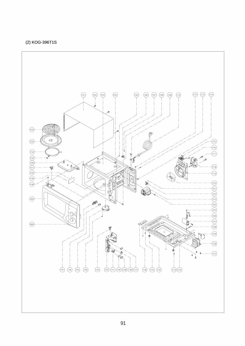
91
(2) KOG-396T1S(2) KOG-396T1S
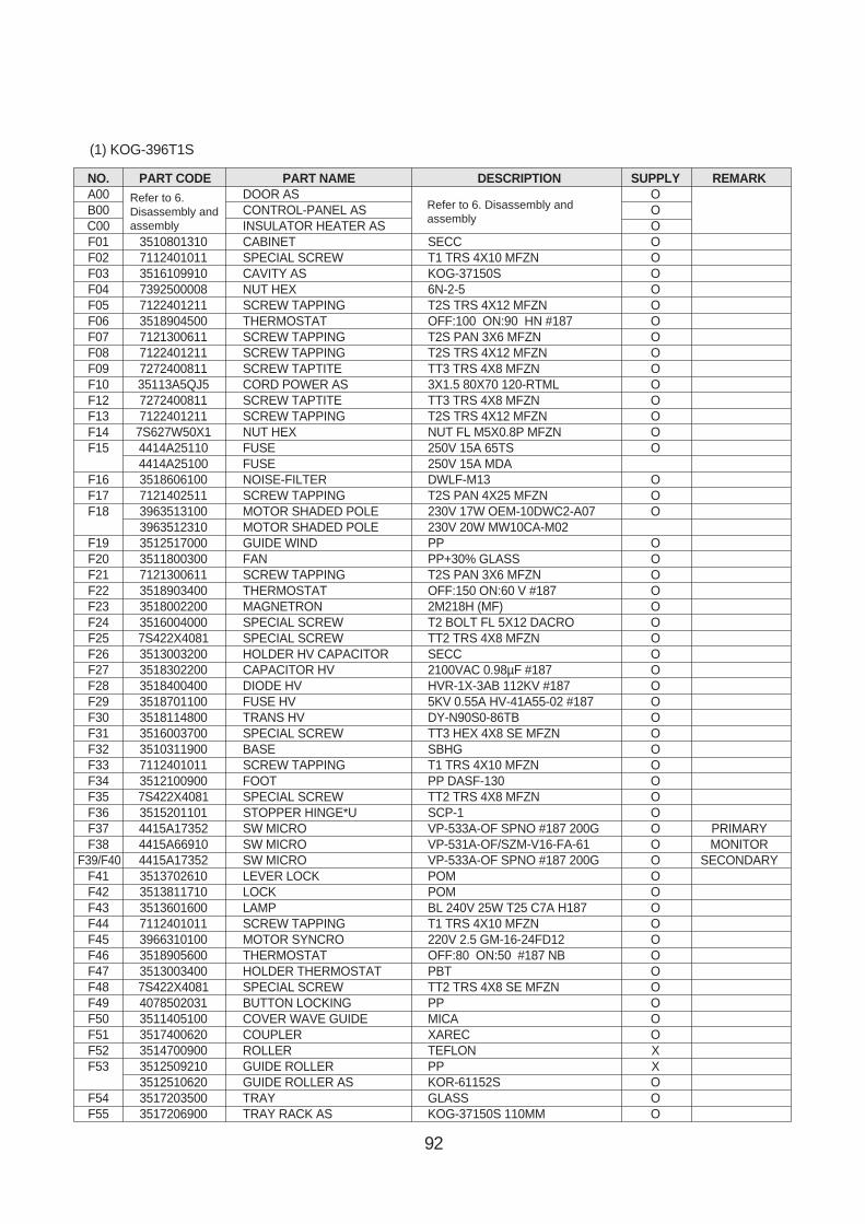
92
NO. PART CODE PART NAME DESCRIPTION SUPPLY REMARKA00 DOOR AS OB00 CONTROL-PANEL AS OC00 INSULATOR HEATER AS OF01 3510801310 CABINET SECC OF02 7112401011 SPECIAL SCREW T1 TRS 4X10 MFZN OF03 3516109910 CAVITY AS KOG-37150S OF04 7392500008 NUT HEX 6N-2-5 OF05 7122401211 SCREW TAPPING T2S TRS 4X12 MFZN OF06 3518904500 THERMOSTAT OFF:100 ON:90 HN #187 OF07 7121300611 SCREW TAPPING T2S PAN 3X6 MFZN OF08 7122401211 SCREW TAPPING T2S TRS 4X12 MFZN OF09 7272400811 SCREW TAPTITE TT3 TRS 4X8 MFZN OF10 35113A5QJ5 CORD POWER AS 3X1.5 80X70 120-RTML OF12 7272400811 SCREW TAPTITE TT3 TRS 4X8 MFZN OF13 7122401211 SCREW TAPPING T2S TRS 4X12 MFZN OF14 7S627W50X1 NUT HEX NUT FL M5X0.8P MFZN OF15 4414A25110 FUSE 250V 15A 65TS O
4414A25100 FUSE 250V 15A MDAF16 3518606100 NOISE-FILTER DWLF-M13 OF17 7121402511 SCREW TAPPING T2S PAN 4X25 MFZN OF18 3963513100 MOTOR SHADED POLE 230V 17W OEM-10DWC2-A07 O
3963512310 MOTOR SHADED POLE 230V 20W MW10CA-M02F19 3512517000 GUIDE WIND PP OF20 3511800300 FAN PP+30% GLASS OF21 7121300611 SCREW TAPPING T2S PAN 3X6 MFZN OF22 3518903400 THERMOSTAT OFF:150 ON:60 V #187 OF23 3518002200 MAGNETRON 2M218H (MF) OF24 3516004000 SPECIAL SCREW T2 BOLT FL 5X12 DACRO OF25 7S422X4081 SPECIAL SCREW TT2 TRS 4X8 MFZN OF26 3513003200 HOLDER HV CAPACITOR SECC OF27 3518302200 CAPACITOR HV 2100VAC 0.98µF #187 OF28 3518400400 DIODE HV HVR-1X-3AB 112KV #187 OF29 3518701100 FUSE HV 5KV 0.55A HV-41A55-02 #187 OF30 3518114800 TRANS HV DY-N90S0-86TB OF31 3516003700 SPECIAL SCREW TT3 HEX 4X8 SE MFZN OF32 3510311900 BASE SBHG OF33 7112401011 SCREW TAPPING T1 TRS 4X10 MFZN OF34 3512100900 FOOT PP DASF-130 OF35 7S422X4081 SPECIAL SCREW TT2 TRS 4X8 MFZN OF36 3515201101 STOPPER HINGE*U SCP-1 OF37 4415A17352 SW MICRO VP-533A-OF SPNO #187 200G O PRIMARYF38 4415A66910 SW MICRO VP-531A-OF/SZM-V16-FA-61 O MONITOR
F39/F40 4415A17352 SW MICRO VP-533A-OF SPNO #187 200G O SECONDARYF41 3513702610 LEVER LOCK POM OF42 3513811710 LOCK POM OF43 3513601600 LAMP BL 240V 25W T25 C7A H187 OF44 7112401011 SCREW TAPPING T1 TRS 4X10 MFZN OF45 3966310100 MOTOR SYNCRO 220V 2.5 GM-16-24FD12 OF46 3518905600 THERMOSTAT OFF:80 ON:50 #187 NB OF47 3513003400 HOLDER THERMOSTAT PBT OF48 7S422X4081 SPECIAL SCREW TT2 TRS 4X8 SE MFZN OF49 4078502031 BUTTON LOCKING PP OF50 3511405100 COVER WAVE GUIDE MICA OF51 3517400620 COUPLER XAREC OF52 3514700900 ROLLER TEFLON XF53 3512509210 GUIDE ROLLER PP X
3512510620 GUIDE ROLLER AS KOR-61152S OF54 3517203500 TRAY GLASS OF55 3517206900 TRAY RACK AS KOG-37150S 110MM O
Refer to 6.Disassembly andassembly
Refer to 6. Disassembly andassembly
(1) KOG-396T1S

93
1. DOOR ASSEMBLYRefer to Disassembly and assembly
2. CONTROL PANEL ASSEMBL YRefer to Disassembly and assembly
3. TOTAL ASSEMBL Y
(1) KOG-374R0S
EXPLODED VIEW AND PARTS LIST <KOG-374R0S>

94
NO. PART CODE PART NAME DESCRIPTION SUPPLY REMARKA00 DOOR AS OB00 CONTROL-PANEL AS OC00 INSULATOR HEATER AS OF01 3510801310 CABINET SECC OF02 7112401011 SPECIAL SCREW T1 TRS 4X10 MFZN OF03 3516109610 CAVITY AS KOG-37150S OF04 7392500008 NUT HEX 6N-2-5 OF05 7122401211 SCREW TAPPING T2S TRS 4X12 MFZN OF06 3518904500 THERMOSTAT OFF:100 ON:90 HN #187 OF07 7121300611 SCREW TAPPING T2S PAN 3X6 MFZN OF08 7122401211 SCREW TAPPING T2S TRS 4X12 MFZN OF09 7272400811 SCREW TAPTITE TT3 TRS 4X8 MFZN OF10 35113A5QJ5 CORD POWER AS 3X1.5 80X70 120-RTML OF12 7272400811 SCREW TAPTITE TT3 TRS 4X8 MFZN OF13 7122401211 SCREW TAPPING T2S TRS 4X12 MFZN OF14 7S627W50X1 NUT HEX NUT FL M5X0.8P MFZN O
F154414A25110 FUSE 250V 15A 65TS O4414A25100 FUSE 250V 15A MDA
F16 3518606100 NOISE-FILTER DWLF-M13 OF17 7121402511 SCREW TAPPING T2S PAN 4X25 MFZN OF18 3512517000 GUIDE WIND PP O
F193963513100 MOTOR SHADED POLE 230V 17W OEM-10DWC2-A07 O3963512310 MOTOR SHADED POLE 230V 20W MW10CA-M02
F20 3511800300 FAN PP+30% GLASS OF21 3518002200 MAGNETRON 2M218H (MF) OF22 3516004000 SPECIAL SCREW T2 BOLT FL 5X12 DACRO OF23 7S422X4081 SPECIAL SCREW TT2 TRS 4X8 MFZN OF24 3513003200 HOLDER HV CAPACITOR SECC OF25 3518302200 CAPACITOR HV 2100VAC 0.98µF #187 OF26 3518400400 DIODE HV HVR-1X-3AB 112KV #187 OF27 3518701100 FUSE HV 5KV 0.55A HV-41A55-02 #187 OF28 3518113700 TRANS HV DY-N80S0-63T OF29 3516003700 SPECIAL SCREW TT3 HEX 4X8 MFZN OF30 3510311700 BASE SBHG O KOG-37150SF31 7112401011 SCREW TAPPING T1 TRS 4X10 MFZN OF32 3512100900 FOOT PP DASF-130 OF33 7S422X4081 SPECIAL SCREW TT2 TRS 4X8 MFZN OF34 3515201101 STOPPER HINGE*U SCP-1 OF35 4415A17352 SW MICRO VP-533A-OF SPNO #187 200G O PRIMARYF36 4415A66910 SW MICRO VP-531A-OF/SZM-V16-FA-61 O MONITOR
F37/F38 4415A17352 SW MICRO VP-533A-OF SPNO #187 200G O SECONDARYF39 3513702610 LEVER LOCK POM OF40 3513811710 LOCK POM OF41 3513601600 LAMP BL 240V 25W T25 C7A H187 OF42 7112401011 SCREW TAPPING T1 TRS 4X10 MFZN OF43 3966310100 MOTOR SYNCRO 220V 2.5 GM-16-24FD12 OF44 3518905300 THERMOSTAT OFF:75 ON:65 #187 NB OF45 3513003400 HOLDER THERMOSTAT PBT OF46 7S422X4081 SPECIAL SCREW TT2 TRS 4X8 SE MFZN OF47 3511405100 COVER WAVE GUIDE MICA OF48 3517400620 COUPLER XAREC OF49 3514700710 ROLLER TEFLON X
F503512517300 GUIDE ROLLER PP 5113MF6 A353B X3512517500 GUIDE ROLLER AS KOR-63150S O
F51 3517203600 TRAY GLASS OF52 3517206900 TRAY RACK AS KOG-37150S 110MM O
Refer to 6.Disassembly andassembly
Refer to 6. Disassembly andassembly
(1) KOG-374R0S
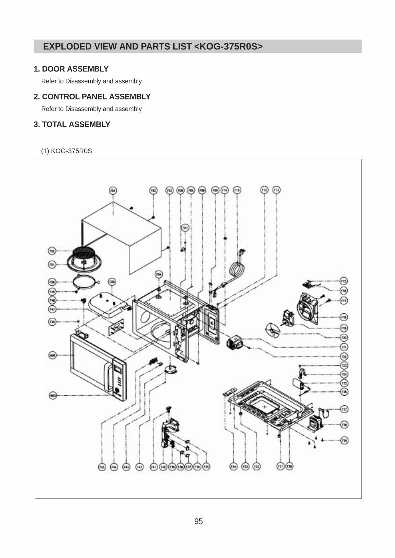
95
1. DOOR ASSEMBLYRefer to Disassembly and assembly
2. CONTROL PANEL ASSEMBL YRefer to Disassembly and assembly
3. TOTAL ASSEMBL Y
(1) KOG-375R0S
EXPLODED VIEW AND PARTS LIST <KOG-375R0S>
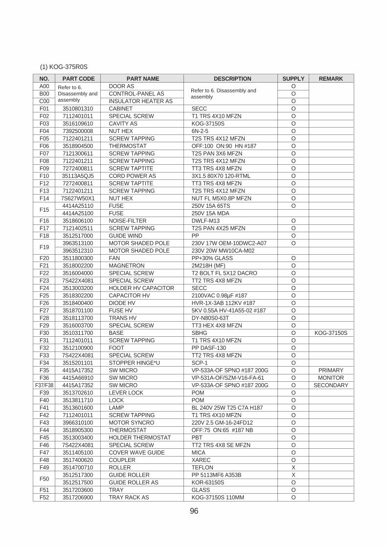
96
NO. PART CODE PART NAME DESCRIPTION SUPPLY REMARKA00 DOOR AS OB00 CONTROL-PANEL AS OC00 INSULATOR HEATER AS OF01 3510801310 CABINET SECC OF02 7112401011 SPECIAL SCREW T1 TRS 4X10 MFZN OF03 3516109610 CAVITY AS KOG-37150S OF04 7392500008 NUT HEX 6N-2-5 OF05 7122401211 SCREW TAPPING T2S TRS 4X12 MFZN OF06 3518904500 THERMOSTAT OFF:100 ON:90 HN #187 OF07 7121300611 SCREW TAPPING T2S PAN 3X6 MFZN OF08 7122401211 SCREW TAPPING T2S TRS 4X12 MFZN OF09 7272400811 SCREW TAPTITE TT3 TRS 4X8 MFZN OF10 35113A5QJ5 CORD POWER AS 3X1.5 80X70 120-RTML OF12 7272400811 SCREW TAPTITE TT3 TRS 4X8 MFZN OF13 7122401211 SCREW TAPPING T2S TRS 4X12 MFZN OF14 7S627W50X1 NUT HEX NUT FL M5X0.8P MFZN O
F154414A25110 FUSE 250V 15A 65TS O4414A25100 FUSE 250V 15A MDA
F16 3518606100 NOISE-FILTER DWLF-M13 OF17 7121402511 SCREW TAPPING T2S PAN 4X25 MFZN OF18 3512517000 GUIDE WIND PP O
F193963513100 MOTOR SHADED POLE 230V 17W OEM-10DWC2-A07 O3963512310 MOTOR SHADED POLE 230V 20W MW10CA-M02
F20 3511800300 FAN PP+30% GLASS OF21 3518002200 MAGNETRON 2M218H (MF) OF22 3516004000 SPECIAL SCREW T2 BOLT FL 5X12 DACRO OF23 7S422X4081 SPECIAL SCREW TT2 TRS 4X8 MFZN OF24 3513003200 HOLDER HV CAPACITOR SECC OF25 3518302200 CAPACITOR HV 2100VAC 0.98µF #187 OF26 3518400400 DIODE HV HVR-1X-3AB 112KV #187 OF27 3518701100 FUSE HV 5KV 0.55A HV-41A55-02 #187 OF28 3518113700 TRANS HV DY-N80S0-63T OF29 3516003700 SPECIAL SCREW TT3 HEX 4X8 MFZN OF30 3510311700 BASE SBHG O KOG-37150SF31 7112401011 SCREW TAPPING T1 TRS 4X10 MFZN OF32 3512100900 FOOT PP DASF-130 OF33 7S422X4081 SPECIAL SCREW TT2 TRS 4X8 MFZN OF34 3515201101 STOPPER HINGE*U SCP-1 OF35 4415A17352 SW MICRO VP-533A-OF SPNO #187 200G O PRIMARYF36 4415A66910 SW MICRO VP-531A-OF/SZM-V16-FA-61 O MONITOR
F37/F38 4415A17352 SW MICRO VP-533A-OF SPNO #187 200G O SECONDARYF39 3513702610 LEVER LOCK POM OF40 3513811710 LOCK POM OF41 3513601600 LAMP BL 240V 25W T25 C7A H187 OF42 7112401011 SCREW TAPPING T1 TRS 4X10 MFZN OF43 3966310100 MOTOR SYNCRO 220V 2.5 GM-16-24FD12 OF44 3518905300 THERMOSTAT OFF:75 ON:65 #187 NB OF45 3513003400 HOLDER THERMOSTAT PBT OF46 7S422X4081 SPECIAL SCREW TT2 TRS 4X8 SE MFZN OF47 3511405100 COVER WAVE GUIDE MICA OF48 3517400620 COUPLER XAREC OF49 3514700710 ROLLER TEFLON X
F503512517300 GUIDE ROLLER PP 5113MF6 A353B X3512517500 GUIDE ROLLER AS KOR-63150S O
F51 3517203600 TRAY GLASS OF52 3517206900 TRAY RACK AS KOG-37150S 110MM O
Refer to 6.Disassembly andassembly
Refer to 6. Disassembly andassembly
(1) KOG-375R0S
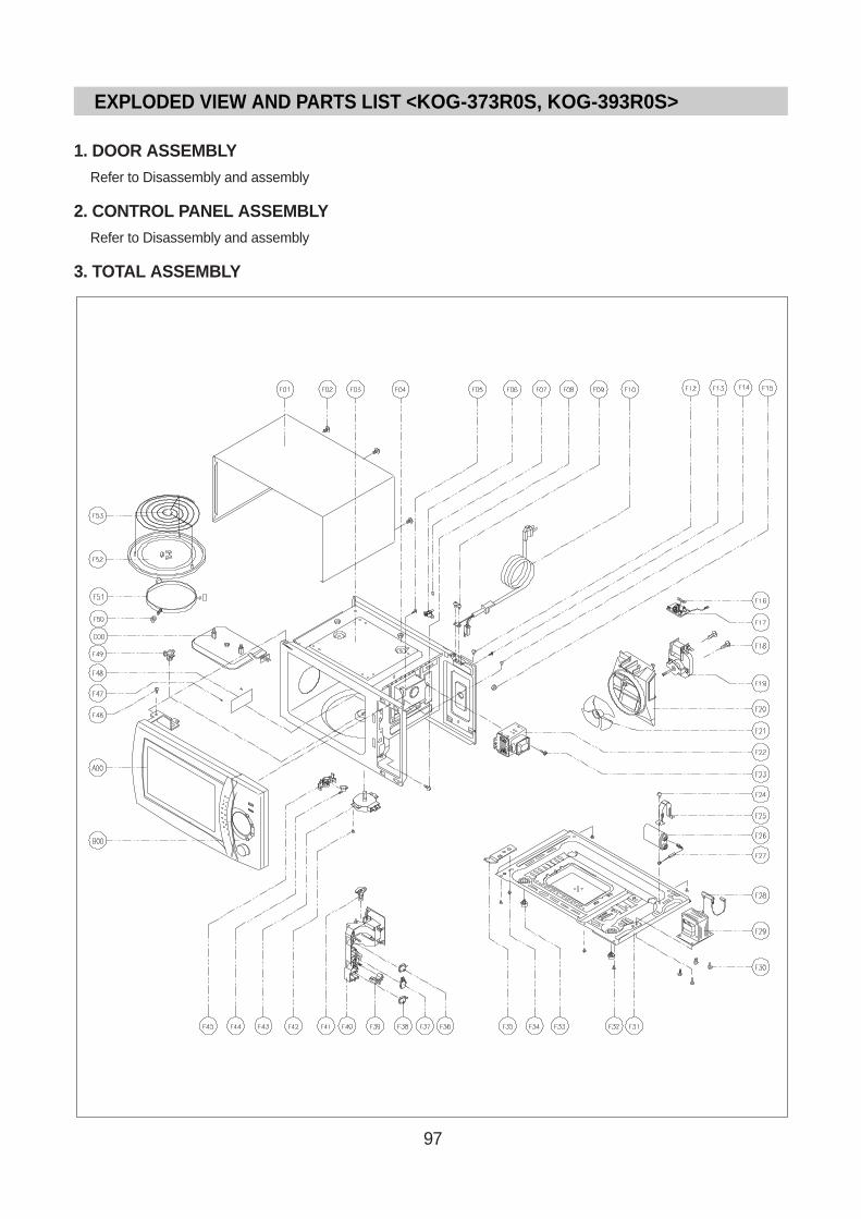
97
1. DOOR ASSEMBLYRefer to Disassembly and assembly
2. CONTROL PANEL ASSEMBL YRefer to Disassembly and assembly
3. TOTAL ASSEMBL Y
EXPLODED VIEW AND PARTS LIST <KOG-373R0S, KOG-393R0S>

98
REF NO PART CODE PART NAME DESCRIPTION Q'TY
A00 3511712170 DOOR AS KOG-63350S 1
B00 PKCPSWZ600 CONTROL PANEL AS KOG-373R0S 1
C00 3513302700 HEATER AS KOG-37150S 1
F01 3510801310 CABINET SECC 1
F02 7112401011 SCREW TAPPING T1 TRS 4X10 MFZN 3
F03 3516109610 CAVITY AS CAVITY AS 1
F04 7392500008 NUT HEX 6N-2-5 2
F05 7122401211 SCREW TAPPING T2S TRS 4X12 MFZN 1
F06 3518904500 THERMOSTAT OFF : 100 ON : 90 HN #187 1
F07 7121300611 SCREW TAPPING T2S PAN 3X6 MFZN 1
F08 7122401211 SCREW TAPPING T2S TRS 4X12 MFZN 1
F09 7112401011 SCREW TAPPING T1 TRS 4X10 MFZN 2
F10 35113A5QJ5 CORD POWER AS 3X1.5 80X80 120-RTML 1.4M 1
F12 7112401011 SCREW TAPPING T1 TRS 4X10 MFZN 1
F13 7122401211 SCREW TAPPING T2S TRS 4X12 MFZN 1
F14 7112401011 SCREW TAPPING T1 TRS 4X10 MFZN 1
F15 7S627W50X1 NUT HEX NUT FLANGE M5X0.8P MFZN 1
F16 4414A25110 FUSE 250V 15A 65TS 1
4414A25100 FUSE 250V 15A MDA15 1
F17 3518606100 NOISE-FILTER DWLF-M13 1
F18 7121402511 SCREW TAPPING T2S PAN 4X25 MFZN 2
F19 3963513100 MOTOR SHADED POLE 230V 17W OEM-10DWC2-A07 1
3963512310 MOTOR SHADED POLE 230V 20W MW10CA-M02 1
F20 3512517000 GUIDE WIND PP 1
F21 3511800300 FAN PP+30% GLASS 1
F22 3518002200 MAGNETRON 2M218H(MF) 1
F23 3516004000 SPECIAL SCREW T2 BOLT FLANGE 5X12 DACRO 1
F24 7S422X4081 SPECIAL SCREW TT2 TRS 4X8 SE MFZN 1
F25 3513003200 HOLDER HV CAPACITOR SECC 1
F26 3518302200 CAPACITOR HV 2100VAC 0.98µF #187 1
F27 3518400400 DIODE HV HVR-1X-3AB 12KV #187 1
F28 3518701100 FUSE HV 5KV 0.55A HV-41A55-02 1
F29 3518113700 TRANS HV DY-N80S0-63T 1
F30 3516003700 SPECIAL SCREW TT3 HEX 4X8 FLG MFZN 4
F31 3510311700 BASE SBHG 1
F32 7112401011 SCREW TAPPING T1 TRS 4X10 MFZN 5
(1) KOG-373R0S
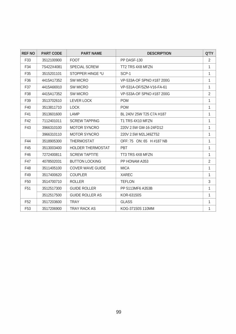
99
REF NO PART CODE PART NAME DESCRIPTION Q'TY
F33 3512100900 FOOT PP DASF-130 2
F34 7S422X4081 SPECIAL SCREW TT2 TRS 4X8 MFZN 1
F35 3515201101 STOPPER HINGE *U SCP-1 1
F36 4415A17352 SW MICRO VP-533A-OF SPNO #187 200G 1
F37 4415A66910 SW MICRO VP-531A-OF/SZM-V16-FA-61 1
F38 4415A17352 SW MICRO VP-533A-OF SPNO #187 200G 2
F39 3513702610 LEVER LOCK POM 1
F40 3513811710 LOCK POM 1
F41 3513601600 LAMP BL 240V 25W T25 C7A H187 1
F42 7112401011 SCREW TAPPING T1 TRS 4X10 MFZN 1
F43 3966310100 MOTOR SYNCRO 220V 2.5W GM-16-24FD12 1
3966310110 MOTOR SYNCRO 220V 2.5W M2LJ49ZT52 1
F44 3518905300 THERMOSTAT OFF: 75 ON: 65 H #187 NB 1
F45 3513003400 HOLDER THERMOSTAT PBT 1
F46 7272400811 SCREW TAPTITE TT3 TRS 4X8 MFZN 1
F47 4078502031 BUTTON LOCKING PP HONAM A353 2
F48 3511405100 COVER WAVE GUIDE MICA 1
F49 3517400620 COUPLER XAREC 1
F50 3514700710 ROLLER TEFLON 3
F51 3512517300 GUIDE ROLLER PP 5113MF6 A353B 1
3512517500 GUIDE ROLLER AS KOR-63150S 1
F52 3517203600 TRAY GLASS 1
F53 3517206900 TRAY RACK AS KOG-37150S 110MM 1
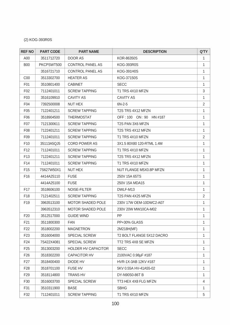
100
REF NO PART CODE PART NAME DESCRIPTION Q'TY
A00 3511712720 DOOR AS KOR-86350S 1
B00 PKCPSWT500 CONTROL PANEL AS KOG-393R0S 1
3516721710 CONTROL PANEL AS KOG-391H0S 1
C00 3513302700 HEATER AS KOG-37150S 1
F01 3510801400 CABINET SECC 1
F02 7112401011 SCREW TAPPING T1 TRS 4X10 MFZN 3
F03 3516109910 CAVITY AS CAVITY AS 1
F04 7392500008 NUT HEX 6N-2-5 2
F05 7122401211 SCREW TAPPING T2S TRS 4X12 MFZN 1
F06 3518904500 THERMOSTAT OFF : 100 ON : 90 HN #187 1
F07 7121300611 SCREW TAPPING T2S PAN 3X6 MFZN 1
F08 7122401211 SCREW TAPPING T2S TRS 4X12 MFZN 1
F09 7112401011 SCREW TAPPING T1 TRS 4X10 MFZN 2
F10 35113A5QJ5 CORD POWER AS 3X1.5 80X80 120-RTML 1.4M 1
F12 7112401011 SCREW TAPPING T1 TRS 4X10 MFZN 1
F13 7122401211 SCREW TAPPING T2S TRS 4X12 MFZN 1
F14 7112401011 SCREW TAPPING T1 TRS 4X10 MFZN 1
F15 7S627W50X1 NUT HEX NUT FLANGE M5X0.8P MFZN 1
F16 4414A25110 FUSE 250V 15A 65TS 1
4414A25100 FUSE 250V 15A MDA15 1
F17 3518606100 NOISE-FILTER DWLF-M13 1
F18 7121402511 SCREW TAPPING T2S PAN 4X25 MFZN 2
F19 3963513100 MOTOR SHADED POLE 230V 17W OEM-10DWC2-A07 1
3963512310 MOTOR SHADED POLE 230V 20W MW10CA-M02 1
F20 3512517000 GUIDE WIND PP 1
F21 3511800300 FAN PP+30% GLASS 1
F22 3518002200 MAGNETRON 2M218H(MF) 1
F23 3516004000 SPECIAL SCREW T2 BOLT FLANGE 5X12 DACRO 1
F24 7S422X4081 SPECIAL SCREW TT2 TRS 4X8 SE MFZN 1
F25 3513003200 HOLDER HV CAPACITOR SECC 1
F26 3518302200 CAPACITOR HV 2100VAC 0.98µF #187 1
F27 3518400400 DIODE HV HVR-1X-3AB 12KV #187 1
F28 3518701100 FUSE HV 5KV 0.55A HV-41A55-02 1
F29 3518114800 TRANS HV DY-N90S0-86T B 1
F30 3516003700 SPECIAL SCREW TT3 HEX 4X8 FLG MFZN 4
F31 3510311900 BASE SBHG 1
F32 7112401011 SCREW TAPPING T1 TRS 4X10 MFZN 5
(2) KOG-393R0S
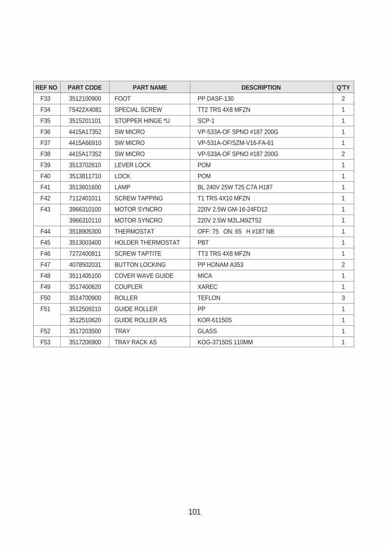
101
REF NO PART CODE PART NAME DESCRIPTION Q'TY
F33 3512100900 FOOT PP DASF-130 2
F34 7S422X4081 SPECIAL SCREW TT2 TRS 4X8 MFZN 1
F35 3515201101 STOPPER HINGE *U SCP-1 1
F36 4415A17352 SW MICRO VP-533A-OF SPNO #187 200G 1
F37 4415A66910 SW MICRO VP-531A-OF/SZM-V16-FA-61 1
F38 4415A17352 SW MICRO VP-533A-OF SPNO #187 200G 2
F39 3513702610 LEVER LOCK POM 1
F40 3513811710 LOCK POM 1
F41 3513601600 LAMP BL 240V 25W T25 C7A H187 1
F42 7112401011 SCREW TAPPING T1 TRS 4X10 MFZN 1
F43 3966310100 MOTOR SYNCRO 220V 2.5W GM-16-24FD12 1
3966310110 MOTOR SYNCRO 220V 2.5W M2LJ49ZT52 1
F44 3518905300 THERMOSTAT OFF: 75 ON: 65 H #187 NB 1
F45 3513003400 HOLDER THERMOSTAT PBT 1
F46 7272400811 SCREW TAPTITE TT3 TRS 4X8 MFZN 1
F47 4078502031 BUTTON LOCKING PP HONAM A353 2
F48 3511405100 COVER WAVE GUIDE MICA 1
F49 3517400620 COUPLER XAREC 1
F50 3514700900 ROLLER TEFLON 3
F51 3512509210 GUIDE ROLLER PP 1
3512510620 GUIDE ROLLER AS KOR-61150S 1
F52 3517203500 TRAY GLASS 1
F53 3517206900 TRAY RACK AS KOG-37150S 110MM 1