da01-english - welcome to advance siam tech thailand ...€¢ machinery and terotechnology •...
TRANSCRIPT
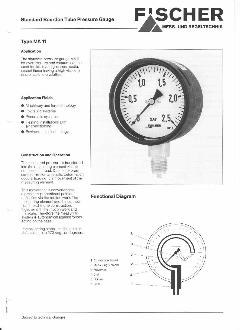


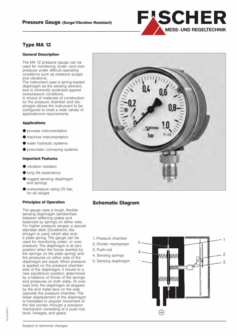
Pressure Gauge (Surge/Vibration Resistant)
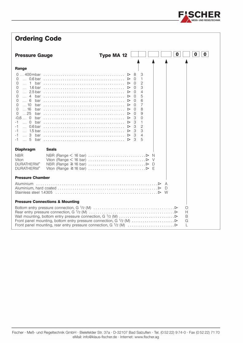
Type MA 12
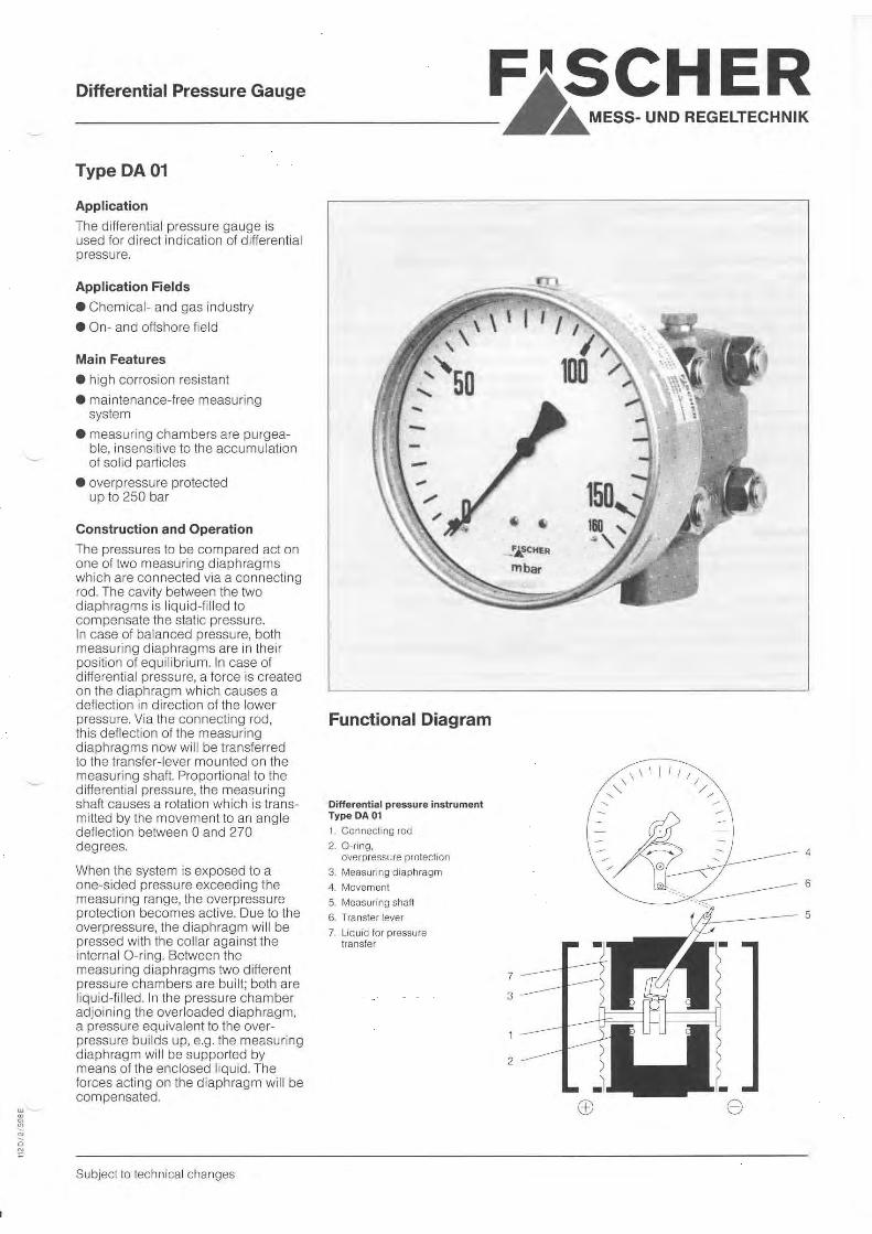
General Description
The MA 12 pressure gauge can beused for monitoring under- and over-pressure under difficult operatingconditions such as pressure surgesand vibrations.The instrument uses a spring-loadeddiaphragm as the sensing element,and is inherently protected againstoverpressure conditions.A choice of materials of constructionfor the pressure chamber and dia-phragm allows the instrument to beconfigured to meet a wide variety ofapplicationns requirements.
Applications
● process instrumentation
● machine instrumentation
● water hydraulic systems
● pneumatic conveying systems
Important Features
● vibration resistant
● long life expectancy
● rugged sensing diaphragm and springs
● overpressure rating 25 bar, for all ranges
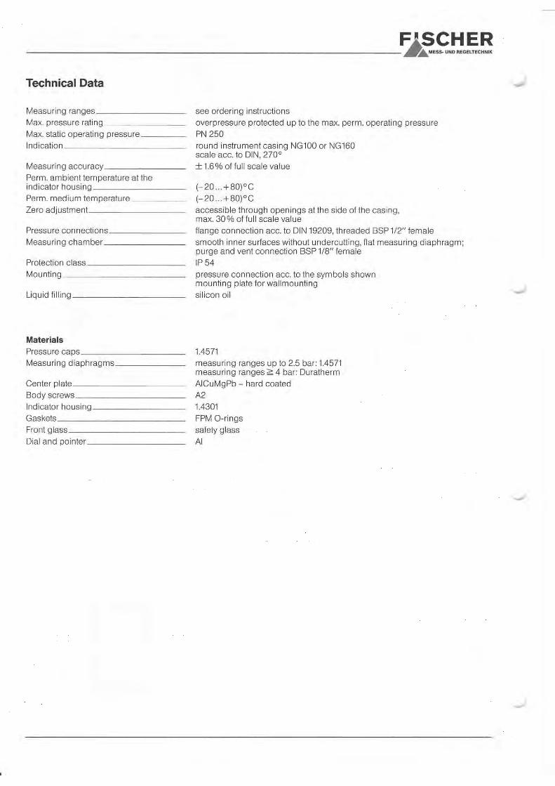
Principles of Operation
The gauge uses a tough, flexible sensing diaphragm sandwiched between stiffening plates and balanced by springs on either side. For higher pressure ranges, a specialstainless steel (Duratherm) dia-phragm is used, which also acts a plate spring. The gauge can beused for monitoring under- or over-pressure. The diaphragm is at zeroposition when the forces exerted bythe springs (or the plate spring) andthe pressures on either side of thediaphragm are equal. When pressureis applied on the pressure chamberside of the diaphragm, it moves to anew equilibrium position, determinedby a balance of forces of the springsand pressures on both sides. At over-load limit, the diaphragm ist stoppedby the end metal face on the sideopposite the pressure chamber. Thelinear displacement of the diaphragmis translated to angular movement ofthe dial pointer, through a precisionmechanism consisting of a push-rod,lever, linkages, and gears.
Subject to technical changes
Schematic Diagram
144 M
/2/0
601
E
FISCHERMESS- UND REGELTECHNIK
1. Pressure chamber
2. Pointer mechanism
3. Push-rod
4. Sensing springs
5. Sensing diaphragm
Specifications
Measuring ranges _ _ _ _ _ _ _ _ _ _ _ _ _ _ _ _ _ _ _ _ _ _ _ _ _ _ _ _ _ _ _ _ _ _ _ _ _ _ _ _ _ _ _ _ _ _ _ _ _ _ _ _ _ _ 0…400 mbar to 0…25 bar (see Ordering Code)
Nominal pressure rating _ _ _ _ _ _ _ _ _ _ _ _ _ _ _ _ _ _ _ _ _ _ _ _ _ _ _ _ _ _ _ _ _ _ _ _ _ _ _ _ 25 bar
Max. overpressure_ _ _ _ _ _ _ _ _ _ _ _ _ _ _ _ _ _ _ _ _ _ _ _ _ _ _ _ _ _ _ _ _ _ _ _ _ _ _ _ _ _ _ _ _ _ _ _ _ _ _ _ _ _ Safe up to nominal pressure rating (all ranges).
Operating temperature ambient _ _ _ _ _ _ _ _ _ _ _ _ _ _ _ _ _ _ _ _ _ _ _ -10 ° to +70 °C (max. 5°C for SEV Approval)
Operating temperature media _ _ _ _ _ _ _ _ _ _ _ _ _ _ _ _ _ _ _ _ _ _ _ _ _ _ _ max. 70 °C
Protection class_ _ _ _ _ _ _ _ _ _ _ _ _ _ _ _ _ _ _ _ _ _ _ _ _ _ _ _ _ _ _ _ _ _ _ _ _ _ _ _ _ _ _ _ _ _ _ _ _ _ _ _ _ _ _ _ _ _ _ _ IP 54 per DIN 40 050
Mounting position_ _ _ _ _ _ _ _ _ _ _ _ _ _ _ _ _ _ _ _ _ _ _ _ _ _ _ _ _ _ _ _ _ _ _ _ _ _ _ _ _ _ _ _ _ _ _ _ _ _ _ _ _ _ _ arbitrary
Accuracy_ _ _ _ _ _ _ _ _ _ _ _ _ _ _ _ _ _ _ _ _ _ _ _ _ _ _ _ _ _ _ _ _ _ _ _ _ _ _ _ _ _ _ _ _ _ _ _ _ _ _ _ _ _ _ _ _ _ _ _ _ _ _ _ _ _ _ _ _ _ _ _ _ _ _ 81.6% of range full-scale
Zero adjustment_ _ _ _ _ _ _ _ _ _ _ _ _ _ _ _ _ _ _ _ _ _ _ _ _ _ _ _ _ _ _ _ _ _ _ _ _ _ _ _ _ _ _ _ _ _ _ _ _ _ _ _ _ _ _ _ _ _ _ by screw, through dial window (front)
Pressure connections _ _ _ _ _ _ _ _ _ _ _ _ _ _ _ _ _ _ _ _ _ _ _ _ _ _ _ _ _ _ _ _ _ _ _ _ _ _ _ _ _ _ _ _ _ threaded plug connector G 1/2 (M), per DIN 16 288
Sensing ElementsRange 10 bar_ _ _ _ _ _ _ _ _ _ _ _ _ _ _ _ _ _ _ _ _ _ _ _ _ _ _ _ _ _ _ _ _ _ _ _ _ _ _ _ _ _ _ _ _ _ _ _ _ _ _ _ _ _ _ _ _ _ _ _ _ _ _ _ _ Sensing spring plus fabric-reinforced elastomer diaphragm
Range 16 bar_ _ _ _ _ _ _ _ _ _ _ _ _ _ _ _ _ _ _ _ _ _ _ _ _ _ _ _ _ _ _ _ _ _ _ _ _ _ _ _ _ _ _ _ _ _ _ _ _ _ _ _ _ _ _ _ _ _ _ _ _ _ _ _ _ DURATHERM®
(stainless steel) diaphragm, acting as a plate spring
MaterialsPressure chamber_ _ _ _ _ _ _ _ _ _ _ _ _ _ _ _ _ _ _ _ _ _ _ _ _ _ _ _ _ _ _ _ _ _ _ _ _ _ _ _ _ _ _ _ _ _ _ _ _ _ _ _ _ _ Aluminium Gk Al Si 12 (Cu) painted black
Aluminium Gk Al Si 12 (Cu) with hard coat surface protection
Stainless steel 1.4305
Diaphragm and seals Elastomer _ _ _ _ _ _ _ _ _ _ _ _ _ _ _ _ _ _ _ _ _ Diaphragm and seals: NBR (nitrile) or Viton (fluorocarbon)
Plate spring diaphragm: DURATHERM®
(stainless steel)
Other parts in contact with media_ _ _ _ _ _ _ _ _ _ _ _ _ _ _ _ _ _ _ Stainless steel 1.4310, 1.4305
Housing _ _ _ _ _ _ _ _ _ _ _ _ _ _ _ _ _ _ _ _ _ _ _ _ _ _ _ _ _ _ _ _ _ _ _ _ _ _ _ _ _ _ _ _ _ _ _ _ _ _ _ _ _ _ _ _ _ _ _ _ _ _ _ _ _ _ _ _ _ _ _ _ _ _ _ _ _ Makrolon
Weight_ _ _ _ _ _ _ _ _ _ _ _ _ _ _ _ _ _ _ _ _ _ _ _ _ _ _ _ _ _ _ _ _ _ _ _ _ _ _ _ _ _ _ _ _ _ _ _ _ _ _ _ _ _ _ _ _ _ _ _ _ _ _ _ _ _ _ _ _ _ _ _ _ _ _ _ _ _ _ _ _ With aluminium pressure chamber: 1.2 kg
With stainless steel pressure chamber: 3.5 kg
Mounting/Installation_ _ _ _ _ _ _ _ _ _ _ _ _ _ _ _ _ _ _ _ _ _ _ _ _ _ _ _ _ _ _ _ _ _ _ _ _ _ _ _ _ _ _ Tube mounting: Threaded connectors per DIN 16 288;
(bottom or rear entry pressure connection)
Wall mounting: three integral mounting tabs (bottom entry
pressure connection only)
Front panel mounting: front panel adaptor ring, 132 mm dia.
(Adaptor kit DZ 11) (bottom or rear entry
pressure connection)
Accessories _ _ _ _ _ _ _ _ _ _ _ _ _ _ _ _ _ _ _ _ _ _ _ _ _ _ _ _ _ _ _ _ _ _ _ _ _ _ _ _ _ _ _ _ _ _ _ _ _ _ _ _ _ _ _ _ _ _ _ _ _ _ _ _ Pressure gauge acessories per Data Sheet MZ…
e.g. gauge isolating valve, etc.
Wall holder per DIN 16 281
FISCHERMESS- UND REGELTECHNIK

FISCHERMESS- UND REGELTECHNIK
MA 12 Standard Configuration
MA 12 Wall Mounting
SW 22
Threaded plug (M)per DIN 16288
G 1/2
∅17,5
87,5
20
12
5
∅104
∅ 6
SW 22
∅17,5
G 1/2
∅ 4,8
30°
5
87,5
20
LK ∅
116
∅10
4
∅12
7
16,5∅ 6
Threaded plug (M)per DIN 16288
3x12
0°
Threaded plug (M)per DIN 16288
G 1/2
520
87,5
Pan
el c
ut-o
ut ∅1
04
LK ∅
116
– ∅
4,8
3x1
20°
∅13
2
98,5 min. 3
5
32
∅ 6
∅17,5
MA 12 Front Panel Mounting
FISCHERMESS- UND REGELTECHNIK
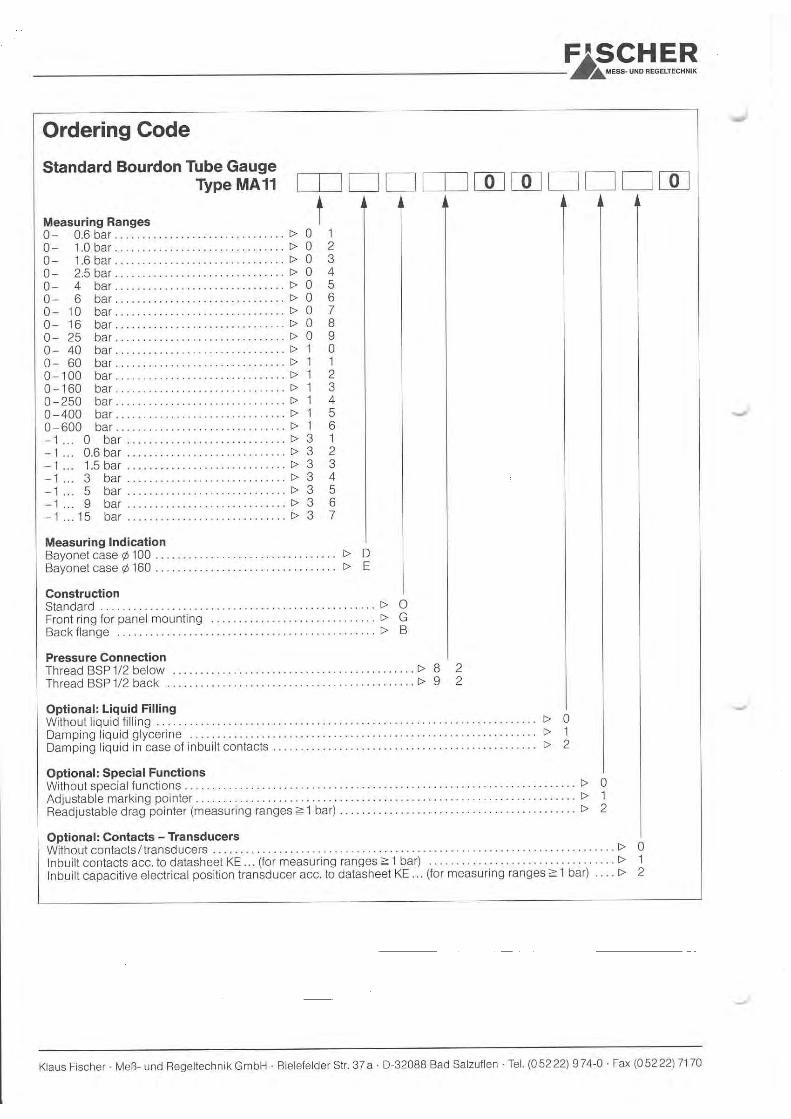
Ordering Code
Type MA 12 0 0 0Pressure Gauge
Range
0 … 400mbar . . . . . . . . . . . . . . . . . . . . . . . . . . . . . . . . . . . . . . T 8 3
0 … 0.6 bar . . . . . . . . . . . . . . . . . . . . . . . . . . . . . . . . . . . . . . T 0 1
0 … 1 bar . . . . . . . . . . . . . . . . . . . . . . . . . . . . . . . . . . . . . . T 0 2
0 … 1.6 bar . . . . . . . . . . . . . . . . . . . . . . . . . . . . . . . . . . . . . . T 0 3
0 … 2.5 bar . . . . . . . . . . . . . . . . . . . . . . . . . . . . . . . . . . . . . . T 0 4
0 … 4 bar . . . . . . . . . . . . . . . . . . . . . . . . . . . . . . . . . . . . . . T 0 5
0 … 6 bar . . . . . . . . . . . . . . . . . . . . . . . . . . . . . . . . . . . . . . T 0 6
0 … 10 bar . . . . . . . . . . . . . . . . . . . . . . . . . . . . . . . . . . . . . . T 0 7
0 … 16 bar . . . . . . . . . . . . . . . . . . . . . . . . . . . . . . . . . . . . . . T 0 8
0 …25 bar . . . . . . . . . . . . . . . . . . . . . . . . . . . . . . . . . . . . . . T 0 9
-0,6 … 0 bar . . . . . . . . . . . . . . . . . . . . . . . . . . . . . . . . . . . . . . T 3 0
-1 … 0 bar . . . . . . . . . . . . . . . . . . . . . . . . . . . . . . . . . . . . . . T 3 1
-1 … 0.6 bar . . . . . . . . . . . . . . . . . . . . . . . . . . . . . . . . . . . . . . T 3 2
-1 … 1.5 bar . . . . . . . . . . . . . . . . . . . . . . . . . . . . . . . . . . . . . . T 3 3
-1 … 3 bar . . . . . . . . . . . . . . . . . . . . . . . . . . . . . . . . . . . . . . T 3 4
-1 … 5 bar . . . . . . . . . . . . . . . . . . . . . . . . . . . . . . . . . . . . . . T 3 5
Diaphragm Seals
NBR NBR (Range < 16 bar) . . . . . . . . . . . . . . . . . . . . . . . . . . .T N
Viton Viton (Range < 16 bar) . . . . . . . . . . . . . . . . . . . . . . . . . . .T V
DURATHERM®
NBR (Range 716 bar) . . . . . . . . . . . . . . . . . . . . . . . . . . .T D
DURATHERM®
Viton (Range 716 bar) . . . . . . . . . . . . . . . . . . . . . . . . . . .T E
Pressure Chamber
Aluminium . . . . . . . . . . . . . . . . . . . . . . . . . . . . . . . . . . . . . . . . . . . . . . . . . . . . . . . . .T A
Aluminium, hard coated . . . . . . . . . . . . . . . . . . . . . . . . . . . . . . . . . . . . . . . . . . . . . . .T D
Stainless steel 1.4305 . . . . . . . . . . . . . . . . . . . . . . . . . . . . . . . . . . . . . . . . . . . . . . . .T W
Pressure Connections & Mounting
Bottom entry pressure connection, G 1/2 (M) . . . . . . . . . . . . . . . . . . . . . . . . . . . . . . . . . . . . . .T O
Rear entry pressure connection, G 1/2 (M) . . . . . . . . . . . . . . . . . . . . . . . . . . . . . . . . . . . . . . . .T H
Wall mounting, bottom entry pressure connection, G 1/2 (M) . . . . . . . . . . . . . . . . . . . . . . . . . .T B
Front panel mounting, bottom entry pressure connection, G 1/2 (M) . . . . . . . . . . . . . . . . . . . .T G
Front panel mounting, rear entry pressure connection, G 1/2 (M) . . . . . . . . . . . . . . . . . . . . . .T L
r r r r
Fischer · Meß- und Regeltechnik GmbH · Bielefelder Str. 37a · D-32107 Bad Salzuflen · Tel. (0 52 22) 9 74-0 · Fax (0 52 22) 7170eMail: [email protected] · Internet: www.fischer.ag
2.3.
06
DB_
GB_
MA1
3_03
06.fm
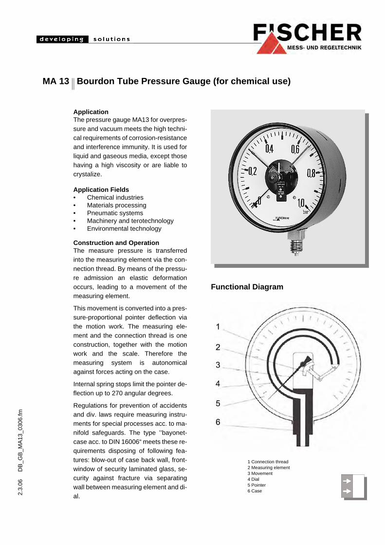
MA 13 Bourdon Tube Pressure Gauge (for chemical use)
ApplicationThe pressure gauge MA13 for overpres-sure and vacuum meets the high techni-cal requirements of corrosion-resistanceand interference immunity. It is used forliquid and gaseous media, except thosehaving a high viscosity or are liable tocrystalize.
Application Fields• Chemical industries• Materials processing• Pneumatic systems• Machinery and terotechnology• Environmental technology
Construction and OperationThe measure pressure is transferredinto the measuring element via the con-nection thread. By means of the pressu-re admission an elastic deformationoccurs, leading to a movement of themeasuring element.
This movement is converted into a pres-sure-proportional pointer deflection viathe motion work. The measuring ele-ment and the connection thread is oneconstruction, together with the motionwork and the scale. Therefore themeasuring system is autonomicalagainst forces acting on the case.
Internal spring stops limit the pointer de-flection up to 270 angular degrees.
Regulations for prevention of accidentsand div. laws require measuring instru-ments for special processes acc. to ma-nifold safeguards. The type ’’bayonet-case acc. to DIN 16006“ meets these re-quirements disposing of following fea-tures: blow-out of case back wall, front-window of security laminated glass, se-curity against fracture via separatingwall between measuring element and di-al.
Functional Diagram
1 Connection thread2 Measuring element3 Movement4 Dial5 Pointer6 Case

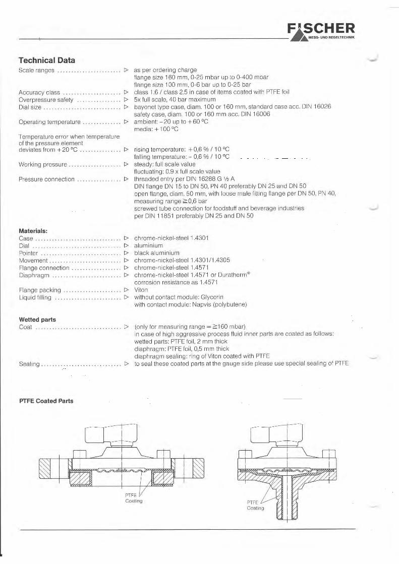
Technical Data
Measuring ranges 0 to 0.6 bar ...0 to 600 bar acc to DIN 16064 ref. to order code
Max. pressure load 1.3 x the measuring end value (for short time)
Accuracy class. 1.0 acc. to DIN 16005
Temperature fault/20°C increasing per 10°C + 0.3%falling per 10°C -0.3%
Ambient temperature -25°C to 60°C
Media temperature max. 100°C
Measuring scale round case diameter 100/160 mm security case diameter 100/160 mm acc. to DIN 16006
Protection class IP54 acc. to DIN 40050
Perm. range of application in case of permanent load: end value of scalein case of alternating load: 0.9fold end value of scale
Pressure connections lower connection BSP ½“ acc. to DIN 16288back connection BSP ½“ excentrical acc. to DIN 16288for casing acc. to DIN 16006 only lower connection possible
MaterialsMeasuring system stainless steel Cr-Ni 1.4571
Case stainless steel Cr-Ni 1.4301Movement stainless steel Cr-Ni 1.4301
Dial aluminium
Pointer aluminium
Optional EquipmentsElectrical equipment Contact modules/transducers (mechanical creep-, magnetic- or inductive
contacts) as well as capacitive swing angle transformers with angle-pro-portional output signals can be integrated within the case which has been enlarged by means of an adequate high bayonet-type face ring. Electrical accessories acc. to datasheet KE...
Liquid filling In case of aggravated operating conditions like vibrations and pressure oscillations, or against condensation in case of outdoor-installation, the case can be filled with damping liquid.
Marking pointer Adjustable pointer for signal marking behind the window.
Drag pointer The drag pointer is carried by the measuring indicator. Between the two pointers does not exist a fixed connection, e.g. once rea-ched maximum values are accumulated. Via an adjusting knob in the win-dow the drag pointer can be readjusted.
Installation/Mounting Screwed tube connection via cutting- or clamping ring connection or direct screwing into the tube by means of appropiate connecting parts and sealing materials. Wallmounting with back flange or gauge support MZ31... Panelmounting via frontring.
Accessories Couplings to further thread diameters, tube connecting screwings, solder- and welding fittings, shut-off valves, manifolds etc. acc. to datasheet MZ...
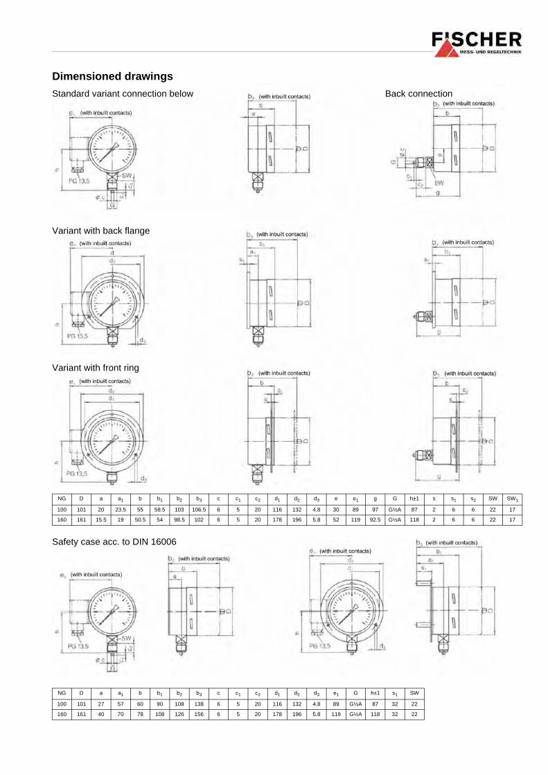
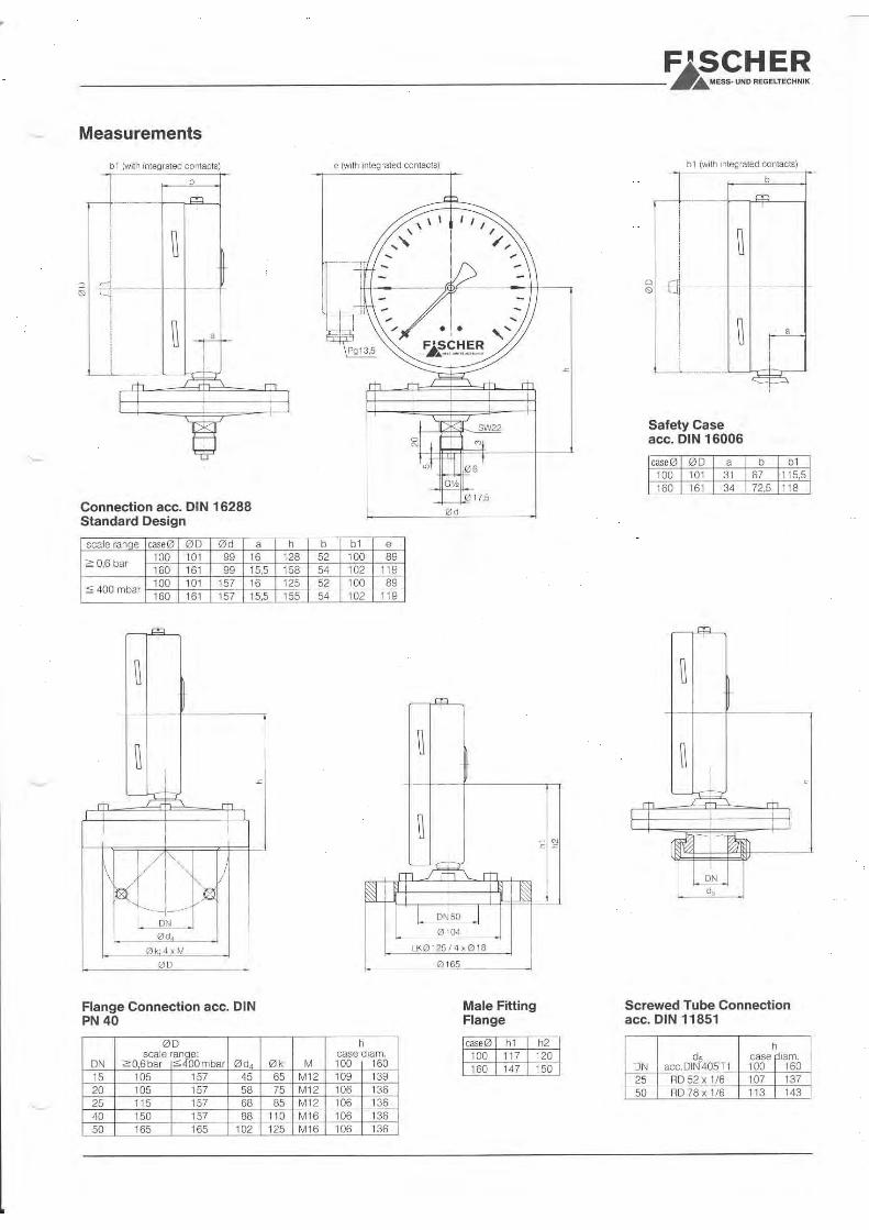
Dimensioned drawings
NG D a a1 b b1 b2 b3 c c1 c2 d1 d2 d3 e e1 g G h±1 s s1 s2 SW SW1
100 101 20 23.5 55 58.5 103 106.5 6 5 20 116 132 4.8 30 89 97 G½A 87 2 6 6 22 17
160 161 15.5 19 50.5 54 98.5 102 6 5 20 178 196 5.8 52 119 92.5 G½A 118 2 6 6 22 17
NG D a a1 b b1 b2 b3 c c1 c2 d1 d2 d3 e1 G h±1 s1 SW
100 101 27 57 60 90 108 138 6 5 20 116 132 4.8 89 G½A 87 32 22
160 161 40 70 78 108 126 156 6 5 20 178 196 5.8 119 G½A 118 32 22
Standard variant connection below Back connection
Variant with back flange
Variant with front ring
Safety case acc. to DIN 16006

Ordering Code
Bourdon Tube Pressure Gauge(for chemical use) Type MA13
Measuring Ranges 0 . . . 0.6 bar......................................................................................... 0 1 0 . . . 1.0 bar......................................................................................... 0 2 0 . . . 1.6 bar......................................................................................... 0 3 0 . . . 2.5 bar......................................................................................... 0 4 0 . . . 4 bar......................................................................................... 0 5 0 . . . 6 bar......................................................................................... 0 6 0 . . . 10 bar......................................................................................... 0 7 0 . . . 16 bar......................................................................................... 0 8 0 . . . 25 bar......................................................................................... 0 9 0 . . . 40 bar......................................................................................... 1 0 0 . . . 60 bar......................................................................................... 1 1 0 . . . 100 bar......................................................................................... 1 2 0 . . . 160 bar......................................................................................... 1 3 0 . . . 250 bar......................................................................................... 1 4 0 . . . 400 bar......................................................................................... 1 5 0 . . . 600 bar......................................................................................... 1 6 -1 . . . 0 bar........................................................................................ 3 1 -1 . . . 0.6 bar........................................................................................ 3 2 -1 . . . 1.5 bar........................................................................................ 3 3 -1 . . . 3 bar........................................................................................ 3 4 -1 . . . 5 bar........................................................................................ 3 5 -1 . . . 9 bar........................................................................................ 3 6 -1 . . . 15 bar........................................................................................ 3 7
Measuring IndicationBayonet case ø 100 .......................................................................................................... LBayonet case ø 160 .......................................................................................................... MSafety case ø 100 acc. to DIN 16006 ............................................................................... OSafety case ø 160 acc. to DIN 16006 ............................................................................... P
ConstructionStandard...................................................................................................................................... O Front ring for panel mounting...................................................................................................... GBack flange ................................................................................................................................. B
Pressure ConnectionThread BSP ½ below............................................................................................................................ 8 7Thread BSP ½ back.............................................................................................................................. 9 7
Optional: Liquid FillingWithout liquid filling ........................................................................................................................................................................ 0Damping liquid glycerine................................................................................................................................................................ 1Damping liquid in case of inbuilt contacts ...................................................................................................................................... 2
Optional: Special FunctionsWithout special functions ......................................................................................................................................................................... 0Adjustable marking pointer ...................................................................................................................................................................... 1Readjustable drag pointer (measuring ranges ≥ 1 bar)............................................................................................................................ 2
Optional: Contacts - TransducersWithout contacts / transducers........................................................................................................................................................................... 0Inbuilt contacts acc. to datasheet KE... (for measuring ranges ≥ 1 bar)............................................................................................................ 1Inbuilt capacitive position transducer electrical acc. to datasheet KE... (for measuring ranges ≥ 1 bar) ........................................................... 2
0 0 0
Technische Änderungen vorbehalten • Subject to change without notice • Changements techniques sous réserve
Fischer Mess- und Regeltechnik GmbH • Bielefelder Str. 37a • D-32107 Bad Salzuflen • Tel. +49 (0) 5222 9740 • Fax +49 (0) 5222 7170 • eMail: [email protected] • www.fischer.ag


Diaphragm Seals
Type MD 03
General Description
Diaphragm seals of the MD 03series are designed for used in food and beverages industries, andconform to DIN 11851 standardspecifications.
Applications
Diaphragm seals are used to isolate pressure / differential pressuremeasuring instruments such asgauges, transmitters, or sensors,from the media to be measured.
In the food and drinks industry,diaphragm seals must conform tostandards of hygiene. Materials andmanufacturing proceesses usedensure that they have the necessarycorrosion resistance and functionalsafety.
All surfaces coming into contactwith the product are processedextremely carefully to a fine degreeof surface finish, and all mediacontact parts are free of undercutsand recesses, so that there are noplaces for micro-organisms orbacteria to accumulate.
Conformity to DIN 11851 standardsensures quick installation and remo-val of diaphragm seals and measu-ring instruments, and thereforemakes cleaning or sterilisation verysimple.
Important Features
● can be sterilised● easy installation and removal● corrosion resistant materials● conforms to DIN 11851 specifications
Principles of Operation
A diaphragm seal provides a fluid-filled isolation stage betweenthe pressure medium (5) and sensitive parts of the measuringdevice (4). A flexible diaphragm (1)of suitable material (generally stain-less steel) is the primary barrier between the pressure media andthe measuring device. The spacebetween the isolating diaphragmand the sensing surface of the measuring device is filled with special liquid (3), in this case vegetable oil. Media pressure (P) istransferred to the measuring devicethrough the flexible diaphragm andfilling liquid.
Subject to technical changes
032 M
/2/0
601
E
FISCHERMESS- UND REGELTECHNIK
1. Diaphragm2. Diaphragm seal housing3. Filling liquid4. Pressure measuring device5. Pressure medium

FISCHERMESS- UND REGELTECHNIK
SpecificationsSelection Criteria To select a suitable diaphragm seal for a particular application,
serval factors need to be considered:
● application details
● required displacement volume
● temperature of the pressure media
The manufacturer’s recommendations should be followed.
Nominal size: ____________________________ DN 25 32 40 50
Nominal pressure: _______________________ PN 40 40 40 25
Displacement volume: ___________________ cc 0.3 0.3 0.35 0.35
Instrument connection ___________________ Threaded socket: G1/2 or G1/4
Process connection______________________ DIN standard hygenic female threaded coupling
Liquid filling ______________________________ Vegetable oil
Operating temperature __________________ –10°C to +120°C
Instrument assembly_____________________ MD 03 diaphragm seals are available without or with capillary tube separation
(1, 2.5, 5, 10 m). Without capillary tubing the diaphragm seal is directly coupled
to the measuring device.
Materials
Diaphragm seal casing__________________ Stainless steel 1.4571
Diaphragm _______________________________ Stainless steel 1.4571
Process coupling ________________________ Stainless steel 1.4305
Capillary tubes and instrument socket__ Stainless steel 1.4571
DINd5 G
to DIN 405 T1
25 RD 52 x 1/6 G1/2
32 RD 58 x 1/6 G1/2
40 RD 65 x 1/6 G1/2
50 RD 78 x 1/6 G1/2
Odering Code
Diaphragm seals for food and beverage industries (per DIN 11851)
Type MD 03
Nominal sizeDN 25 (nominal pressure 40 bar)T 2 5DN 32 (nominal pressure 40 bar)T 3 2DN 40 (nominal pressure 40 bar)T 4 0DN 50 (nominal pressure 25 bar)T 5 0
Nominal pressure rating25 bar . . . . . . . . . . . . . . . . . . . . . . . . . . . . . . . . . . . . T G40 bar . . . . . . . . . . . . . . . . . . . . . . . . . . . . . . . . . . . . T H
Material of measuring system
Instrument connectionThreaded socket G 1/2" (F) . . . . . . . . . . . . . . . . . . . . . . . . . . . . . . . . . T O 3 01 m capillary tube with threaded coupling G 1/4" (F) . . . . . . . . . T K 1 12,5 m capillary tube with threaded coupling G 1/4" (F) . . . . . . . . . T K 1 25 m capillary tube with threaded coupling G 1/4" (F) . . . . . . . . . T K 1 310 m capillary tube with threaded coupling G 1/4" (F) . . . . . . . . . T K 1 41 m capillary tube with threaded coupling G 1/2" (F) . . . . . . . . . T K 3 12,5 m capillary tube with threaded coupling G 1/2" (F) . . . . . . . . . T K 3 25 m capillary tube with threaded coupling G 1/2" (F) . . . . . . . . . T K 3 310 m capillary tube with threaded coupling G 1/2" (F) . . . . . . . . . T K 3 4
AssemblyDiaphragm seal only . . . . . . . . . . . . . . . . . . . . . . . . . . . . . . . . . . . . . . . . . . . . . . . . . . . . . . . . . T 0Diaphragm seal assembled with pressure gauge/transmitter . . . . . . . . . . . . . . . . . . . . . . . . T 1
V
rrrrrrr
G
SW 27
G
SW 27
∅d 4
∅ 26
Capillary tube
42
Fischer · Meß- und Regeltechnik GmbH · Bielefelder Str. 37a · D-32107 Bad Salzuflen · Tel. (0 52 22) 9 74-0 · Fax (0 52 22) 7170eMail: [email protected] · Internet: www.fischer.ag
Diaphragm Seals
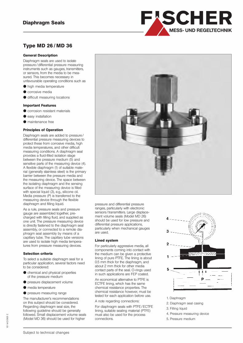
Type MD 26 / MD 36
General Description
Diaphragm seals are used to isolate
pressure /differential pressure measuring
instruments such as gauges, transmitters,
or sensors, from the media to be mea-
sured. This becomes necessary in
unfavourable operating conditions such as
● high media temperature
● corrosive media
● difficult measuring locations
Important Features
● corrosion resistant materials
● easy installation
● maintenance free
Principles of Operation
Diaphragm seals are added to pressure /
differential pressure measuring devices to
protect these from corrosive media, high
media temperatures, and other difficult
measuring conditions. A diaphragm seal
provides a fluid-filled isolation stage
between the pressure medium (5) and
sensitive parts of the measuring device (4).
A flexible diaphragm (1) of suitable mate-
rial (generally stainless steel) is the primary
barrier between the pressure media and
the measuring device. The space between
the isolating diaphragm and the sensing
surface of the measuring device is filled
with special liquid (3), e.g., silicone oil.
Media pressure (P) is transferred to the
measuring device through the flexible
diaphragm and filling liquid.
As a rule, pressure seals and pressure
gauge are assembled together, pre-
charged with filling fluid, and supplied as
one unit. The pressure measuring device
is directly fastened to the diaphragm seal
assembly, or connected to a remote dia-
phragm seal assembly by means of a
capillary tube. The capillary tube versions
are used to isolate high media tempera-
tures from pressure measuring devices.
Selection criteria
To select a suitable diaphragm seal for a
particular application, several factors need
to be considered:
● chemical and physical properties
of the pressure medium
● pressure displacement volume
● media temperature
● pressure measuring range
The manufacturer’s recommendations
on this subject should be considered.
Regarding diaphragm seal size, the
following guideline should be generally
followed. Small displacement volume seals
(Model MD 36) should be used for higher
Subject to technical changes
101
M/2
/0601
E
FISCHERMESS- UND REGELTECHNIK
pressure and differential pressure
ranges, particularly with electronic
sensors / transmitters. Large displace-
ment volume seals (Model MD 26)
should be used for low pressure and
differential pressure applications,
particularly when mechanical gauges
are used.
Lined system
For particularly aggressive media, all
components coming into contact with
the medium can be given a protective
lining of pure PTFE. The lining is about
0.5 mm thick for the diaphragm, and
about 2 mm thick for other media
contact parts of the seal. O-rings used
in such applications are FEP coated.
An economical alternative to PTFE is
ECTFE lining, which has the same
chemical resistance properties. The
chemical resistance however, must be
tested for each application before use.
A note regarding connections:
For diaphragm seals with PTFE /ECTFE
lining, suitable sealing material (PTFE)
must also be used for the process
connections.
1. Diaphragm
2. Diaphragm seal casing
3. Filling liquid
4. Pressure measuring device
5. Pressure medium

G 1/2
G 1/2
SW 27
SW 22
205
∅ 17,5∅ 6
∅ D
PTFE linings
With PTFE linings
With capillary separation
Standard configuration
Capillary tube
H
Typ øD H
MD 26 157 106
MD 36 99 108
FISCHERMESS- UND REGELTECHNIK
Specifications
Type _ _ _ _ _ _ _ _ _ _ _ _ _ _ _ _ _ _ _ _ _ _ _ _ _ _ _ _ _ _ _ _ _ _ _ _ _ _ _ _ _ _ _ _ _ _ _ _ _ _ _ _ _ _ _ _ _ _ _ _ _ _ _ _ _ _ _ _ _ _ _ _ MD 26 MD 36
Pressure rating _ _ _ _ _ _ _ _ _ _ _ _ _ _ _ _ _ _ _ _ _ _ _ _ _ _ _ _ _ _ _ _ _ _ _ _ _ _ _ _ _ _ _ _ _ _ _ _ _ _ PN 40 PN 40
Effective diaphragm diameter _ _ _ _ _ _ _ _ _ _ _ _ _ _ _ _ _ 115 mm 60 mm
Displacement volume _ _ _ _ _ _ _ _ _ _ _ _ _ _ _ _ _ _ _ _ _ _ _ _ _ _ _ _ _ _ _ _ _ _ _ 6.2 cm3 1.2 cm3
Pressure connection: process side _ _ _ _ _ Threaded plug: Threaded plug:DIN 16288-B-G1⁄2 (M) DIN 16288-B-G1⁄2 (M)
Pressure connection:instrument side_ _ _ _ _ _ _ _ _ _ _ _ _ _ _ _ _ _ _ _ _ _ _ _ _ _ _ _ _ _ _ _ _ _ _ _ _ _ _ _ _ _ _ _ _ _ _ _ _ _ DIN 16288-Z-G1⁄2 DIN 16288-Z-G1⁄2
Liquid filling _ _ _ _ _ _ _ _ _ _ _ _ _ _ _ _ _ _ _ _ _ _ _ _ _ _ _ _ _ _ _ _ _ _ _ _ _ _ _ _ _ _ _ _ _ _ _ _ _ _ _ _ _ _ _ _ _ Silicone oil Silicone oil
Operating temperature_ _ _ _ _ _ _ _ _ _ _ _ _ _ _ _ _ _ _ _ _ _ _ _ _ _ _ _ _ _ _ _ _ – 20 °C to + 200 °C – 20 °C to + 200 °C
Materials
Diaphragmseal housing_ _ _ _ _ _ _ _ _ _ Stainless
steel 1.4571
Diaphragm_ _ _ _ _ _ _ _ _ _ _ _ _ _ Stainlesssteel 1.4571
Screws_ _ _ _ _ _ _ _ _ _ _ _ _ _ _ _ _ _ _ _ _ _ _ A 2
O-rings_ _ _ _ _ _ _ _ _ _ _ _ _ _ _ _ _ _ _ _ _ _ FPM
Capillary tube _ _ _ _ _ _ _ Stainlesssteel 1.4571
Ordering CodeDiaphragm Seal
Type MD8 7 H
Diaphragm diameter130 mm . . . . . . . . . . . . . . . . .T 2 675 mm . . . . . . . . . . . . . . . . .T 3 6
Process connectionThreaded socket: G1⁄2 (F)
Pressure rating40 bar
MaterialsStainless steel . . . . . . . . . . . . . . . . . . . . . . . . . . . . . . . . . . .T VStainless steel with ECTFE coating . . . . . . . . . . . . . . . . . . . .T TStainless steel with PTFE coating . . . . . . . . . . . . . . . . . . . . .T U
Instrument connectionThreaded socket G1⁄2 (F) . . . . . . . . . . . . . . . . . . . . . . . . . . . . . . . . . .T O 30
1 m capillary tube with coupling G1⁄2 (F) . . . . . . . . . . . . . . . . . . .T K 312,5 m capillary tube with coupling G1⁄2 (F) . . . . . . . . . . . . . . . . . . .T K 325 m capillary tube with coupling G1⁄2 (F) . . . . . . . . . . . . . . . . . . .T K 33
10 m capillary tube with coupling G1⁄2 (F) . . . . . . . . . . . . . . . . . . .T K 341 m capillary tube with protective hose and coupling G1⁄2 (F) . . . .T S 312,5 m capillary tube with protective hose and coupling G1⁄2 (F) . . . .T S 325 m capillary tube with protective hose and coupling G1⁄2 (F) . . . .T S 33
10 m capillary tube with protective hose and coupling G1⁄2 (F) . . . .T S 34
AssemblyDiaphragm seal only . . . . . . . . . . . . . . . . . . . . . . . . . . . . . . . . . . . . . . . . . . . . . . . .T 0Diaphragm seal assembled with pressure gauge/transmitter . . . . . . . . . . . . . . . . . .T 1
r r r r
Fischer · Meß- und Regeltechnik GmbH · Bielefelder Str. 37a · D-32107 Bad Salzuflen · Tel. (0 52 22) 9 74-0 · Fax (0 52 22) 7170eMail: [email protected] · Internet: www.fischer.ag
The following pressureinstruments are compatiblewith diaphragm seal Models MD 26/MD 36:
MD 26
DA 03 (bar)DS 11 (bar/mbar)DA 12 (bar/mbar)DS 13 (bar/mbar)DE 16 (bar/mbar)DA 09 (bar)DA 04 (bar/mbar)
MD 36
DE 03 (bar/mbar)MA 03 (bar/mbar)MA 01 (bar/mbar)ME 40 (bar/mbar)
Diaphragm Seals
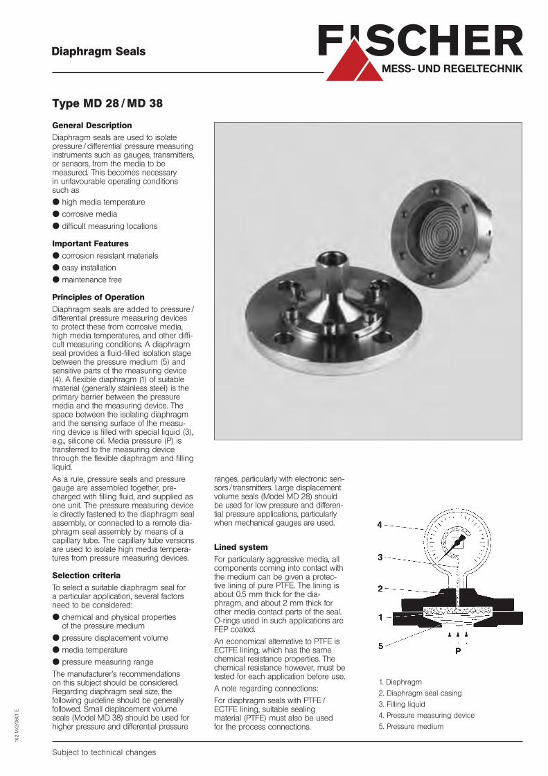
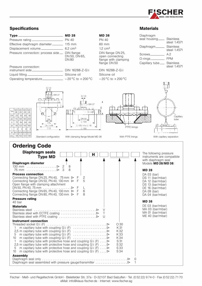
Type MD 28 / MD 38
General Description
Diaphragm seals are used to isolatepressure /differential pressure measuringinstruments such as gauges, transmitters,or sensors, from the media to be measured. This becomes necessary in unfavourable operating conditionssuch as
● high media temperature
● corrosive media
● difficult measuring locations
Important Features
● corrosion resistant materials
● easy installation
● maintenance free
Principles of Operation
Diaphragm seals are added to pressure /differential pressure measuring devicesto protect these from corrosive media,high media temperatures, and other diffi-cult measuring conditions. A diaphragmseal provides a fluid-filled isolation stagebetween the pressure medium (5) andsensitive parts of the measuring device(4). A flexible diaphragm (1) of suitablematerial (generally stainless steel) is theprimary barrier between the pressuremedia and the measuring device. Thespace between the isolating diaphragmand the sensing surface of the measu-ring device is filled with special liquid (3),e.g., silicone oil. Media pressure (P) istransferred to the measuring devicethrough the flexible diaphragm and fillingliquid.
As a rule, pressure seals and pressuregauge are assembled together, pre-charged with filling fluid, and supplied asone unit. The pressure measuring device is directly fastened to the diaphragm sealassembly, or connected to a remote dia-phragm seal assembly by means of acapillary tube. The capillary tube versionsare used to isolate high media tempera-tures from pressure measuring devices.
Selection criteria
To select a suitable diaphragm seal for a particular application, several factorsneed to be considered:
● chemical and physical properties of the pressure medium
● pressure displacement volume
● media temperature
● pressure measuring range
The manufacturer’s recommendations on this subject should be considered.Regarding diaphragm seal size, thefollowing guideline should be generallyfollowed. Small displacement volumeseals (Model MD 38) should be used forhigher pressure and differential pressure
Subject to technical changes
102 M
/2/0
601
E
FISCHERMESS- UND REGELTECHNIK
ranges, particularly with electronic sen-sors / transmitters. Large displacementvolume seals (Model MD 28) shouldbe used for low pressure and differen-tial pressure applications, particularlywhen mechanical gauges are used.
Lined system
For particularly aggressive media, allcomponents coming into contact withthe medium can be given a protec-tive lining of pure PTFE. The lining isabout 0.5 mm thick for the dia-phragm, and about 2 mm thick forother media contact parts of the seal.O-rings used in such applications areFEP coated.
An economical alternative to PTFE isECTFE lining, which has the samechemical resistance properties. Thechemical resistance however, must betested for each application before use.
A note regarding connections:
For diaphragm seals with PTFE /ECTFE lining, suitable sealing material (PTFE) must also be used for the process connections.
1. Diaphragm
2. Diaphragm seal casing
3. Filling liquid
4. Pressure measuring device
5. Pressure medium
FISCHERMESS- UND REGELTECHNIK
G 1/2
G 1/2
65
SW 27
SW 27
DN
∅d 4
∅k, i x M∅ D ∅ 165
∅ 104
DN 50
PTFE linings
With PTFE linings With capillary separationWith clamping flange Model MD 38Standard configuration
Capillarytube
∅ 125 i 4 x ∅ 18
H
Specifications
Type _ _ _ _ _ _ _ _ _ _ _ _ _ _ _ _ _ _ _ _ _ _ _ _ _ _ _ _ _ _ _ _ _ _ _ _ _ _ _ _ _ _ _ _ _ _ _ _ _ _ _ _ _ _ _ _ _ _ _ _ _ _ _ _ _ _ _ _ _ _ _ _ MD 28 MD 38
Pressure rating _ _ _ _ _ _ _ _ _ _ _ _ _ _ _ _ _ _ _ _ _ _ _ _ _ _ _ _ _ _ _ _ _ _ _ _ _ _ _ _ _ _ _ _ _ _ _ _ _ _ PN 40 PN 40
Effective diaphragm diameter _ _ _ _ _ _ _ _ _ _ _ _ _ _ _ _ _ 115 mm 60 mm
Displacement volume _ _ _ _ _ _ _ _ _ _ _ _ _ _ _ _ _ _ _ _ _ _ _ _ _ _ _ _ _ _ _ _ _ _ _ 6.2 cm3 1.2 cm3
Pressure connection: process side _ _ _ _ _ DIN flange DIN flange DN 25,DN 50, DN 65, open connectingDN 80 flange with clamping
flange DN 50
Pressure connection:instrument side_ _ _ _ _ _ _ _ _ _ _ _ _ _ _ _ _ _ _ _ _ _ _ _ _ _ _ _ _ _ _ _ _ _ _ _ _ _ _ _ _ _ _ _ _ _ _ _ _ _ DIN 16288-Z-G1⁄2 DIN 16288-Z-G1⁄2
Liquid filling _ _ _ _ _ _ _ _ _ _ _ _ _ _ _ _ _ _ _ _ _ _ _ _ _ _ _ _ _ _ _ _ _ _ _ _ _ _ _ _ _ _ _ _ _ _ _ _ _ _ _ _ _ _ _ _ _ Silicone oil Silicone oil
Operating temperature_ _ _ _ _ _ _ _ _ _ _ _ _ _ _ _ _ _ _ _ _ _ _ _ _ _ _ _ _ _ _ _ _ – 20 °C to + 200 °C – 20 °C to + 200 °C
Materials
Diaphragmseal housing_ _ _ _ _ _ _ _ _ _ Stainless
steel 1.4571
Diaphragm_ _ _ _ _ _ _ _ _ _ _ _ _ _ Stainlesssteel 1.4571
Screws_ _ _ _ _ _ _ _ _ _ _ _ _ _ _ _ _ _ _ _ _ _ _ A 2
O-rings_ _ _ _ _ _ _ _ _ _ _ _ _ _ _ _ _ _ _ _ _ _ FPM
Capillary tube _ _ _ _ _ _ _ Stainlesssteel 1.4571
TypMD MD MD MD38 28 28 28
DN 25 50 65 80
øD 115 165 185 200
H 75 84 84 84
øk 85 125 145 160
i 4 4 8 8
M M12 M16 M16 M16
ød4 58 102 122 138
Ordering CodeDiaphragm seals
Type MDH
Diaphragm diameter130 mm . . . . . . . . . . . . . . . . .T 2 875 mm . . . . . . . . . . . . . . . . .T 3 8
Process connectionConnecting flange DN 25, PN 40, 75 mm T F 2Connecting flange DN 50, PN 40, 130 mm T F 5Open flange with clamping attachment DN 50, PN 40, 75 mm . . . . . . . . . . . . . . . .T F LConnecting flange DN 65, PN 40, 130 mm T F 6Connecting flange DN 80, PN 40, 130 mm T F 8
Pressure rating40 bar
MaterialsStainless steel . . . . . . . . . . . . . . . . . . . . . . . . . . . . . . . . . . .T VStainless steel with ECTFE coating . . . . . . . . . . . . . . . . . . . .T TStainless steel with PTFE coating . . . . . . . . . . . . . . . . . . . . .T U
Instrument connectionThreaded socket G1⁄2 (F) . . . . . . . . . . . . . . . . . . . . . . . . . . . . . . . . . .T O 30
1 m capillary tube with coupling G1⁄2 (F) . . . . . . . . . . . . . . . . . . .T K 312,5 m capillary tube with coupling G1⁄2 (F) . . . . . . . . . . . . . . . . . . .T K 325 m capillary tube with coupling G1⁄2 (F) . . . . . . . . . . . . . . . . . . .T K 33
10 m capillary tube with coupling G1⁄2 (F) . . . . . . . . . . . . . . . . . . .T K 341 m capillary tube with protective hose and coupling G1⁄2 (F) . . . .T S 312,5 m capillary tube with protective hose and coupling G1⁄2 (F) . . . .T S 325 m capillary tube with protective hose and coupling G1⁄2 (F) . . . .T S 33
10 m capillary tube with protective hose and coupling G1⁄2 (F) . . . .T S 34
AssemblyDiaphragm seal only . . . . . . . . . . . . . . . . . . . . . . . . . . . . . . . . . . . . . . . . . . . . . . . .T 0Diaphragm seal assembled with pressure gauge/transmitter . . . . . . . . . . . . . . . . . .T 1
r r r r r
Fischer · Meß- und Regeltechnik GmbH · Bielefelder Str. 37a · D-32107 Bad Salzuflen · Tel. (0 52 22) 9 74-0 · Fax (0 52 22) 7170eMail: [email protected] · Internet: www.fischer.ag
The following pressureinstruments are compatiblewith diaphragm seal Models MD 28/MD 38:
MD 28
DA 03 (bar)DS 11 (bar/mbar)DA 12 (bar/mbar)DS 13 (bar/mbar)DE 16 (bar/mbar)DA 09 (bar)DA 04 (bar/mbar)
MD 38
DE 03 (bar/mbar)MA 03 (bar/mbar)MA 01 (bar/mbar)ME 40 (bar/mbar)
Digital Manometer
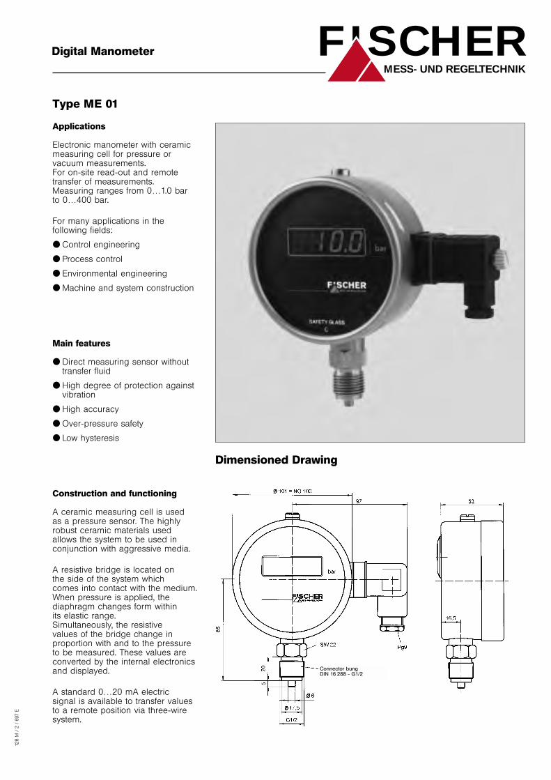
Type ME 01
Applications
Electronic manometer with ceramicmeasuring cell for pressure orvacuum measurements. For on-site read-out and remotetransfer of measurements. Measuring ranges from 0…1.0 bar to 0…400 bar.
For many applications in thefollowing fields:
● Control engineering
● Process control
● Environmental engineering
● Machine and system construction
Main features
● Direct measuring sensor withouttransfer fluid
● High degree of protection againstvibration
● High accuracy
● Over-pressure safety
● Low hysteresis
Construction and functioning
A ceramic measuring cell is used as a pressure sensor. The highlyrobust ceramic materials used allows the system to be used inconjunction with aggressive media.
A resistive bridge is located on the side of the system which comes into contact with the medium.When pressure is applied, thediaphragm changes form within its elastic range.Simultaneously, the resistive values of the bridge change inproportion with and to the pressureto be measured. These values areconverted by the internal electronicsand displayed.
A standard 0…20 mA electric signal is available to transfer valuesto a remote position via three-wiresystem.
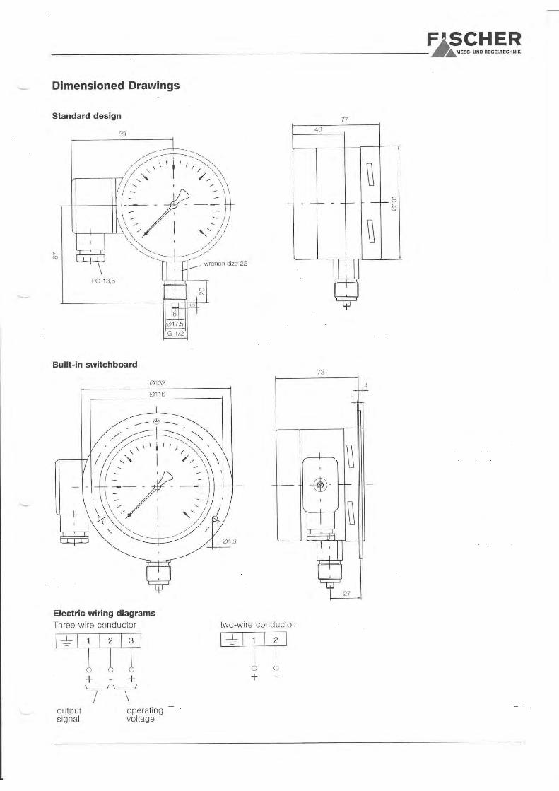
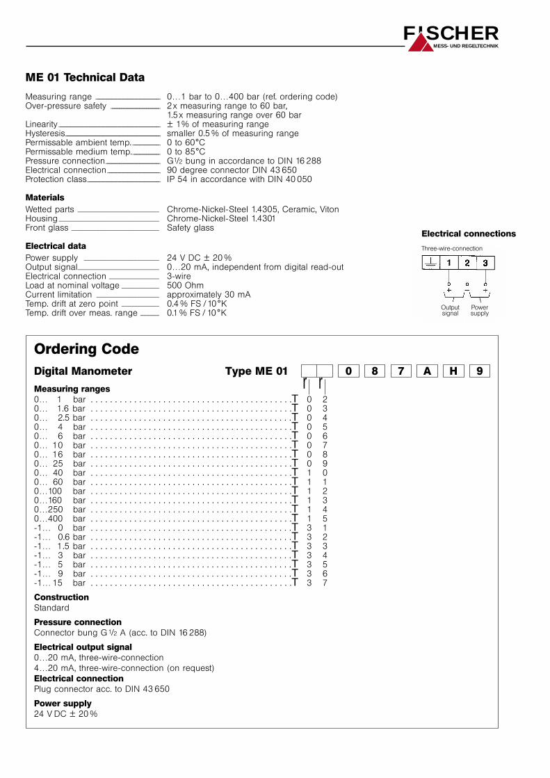
Dimensioned Drawing
128 M
/ 2
/ 6
97 E
FISCHERMESS- UND REGELTECHNIK
Connector bungDIN 16 288 - G1/2
ME 01 Technical Data
Measuring range _ _ _ _ _ _ _ _ _ _ _ _ _ _ _ _ _ _ _ _ _ _ _ _ _ _ _ _ _ _ _ _ _ _ _ _ _ _ 0…1 bar to 0…400 bar (ref. ordering code)Over-pressure safety _ _ _ _ _ _ _ _ _ _ _ _ _ _ _ _ _ _ _ _ _ _ _ _ _ _ _ _ _ 2 x measuring range to 60 bar,
1.5x measuring range over 60 barLinearity _ _ _ _ _ _ _ _ _ _ _ _ _ _ _ _ _ _ _ _ _ _ _ _ _ _ _ _ _ _ _ _ _ _ _ _ _ _ _ _ _ _ _ _ _ _ _ _ _ _ _ _ _ _ _ _ _ _ _ _ ± 1% of measuring rangeHysteresis_ _ _ _ _ _ _ _ _ _ _ _ _ _ _ _ _ _ _ _ _ _ _ _ _ _ _ _ _ _ _ _ _ _ _ _ _ _ _ _ _ _ _ _ _ _ _ _ _ _ _ _ _ _ _ _ smaller 0.5 % of measuring rangePermissable ambient temp._ _ _ _ _ _ _ _ _ _ _ _ _ _ _ _ 0 to 60°CPermissable medium temp._ _ _ _ _ _ _ _ _ _ _ _ _ _ _ _ 0 to 85°CPressure connection_ _ _ _ _ _ _ _ _ _ _ _ _ _ _ _ _ _ _ _ _ _ _ _ _ _ _ _ _ _ _ _ G1/2 bung in accordance to DIN 16 288Electrical connection_ _ _ _ _ _ _ _ _ _ _ _ _ _ _ _ _ _ _ _ _ _ _ _ _ _ _ _ _ _ _ 90 degree connector DIN 43 650Protection class_ _ _ _ _ _ _ _ _ _ _ _ _ _ _ _ _ _ _ _ _ _ _ _ _ _ _ _ _ _ _ _ _ _ _ _ _ _ _ _ _ _ _ IP 54 in accordance with DIN 40 050
Materials
Wetted parts __________________________ Chrome-Nickel-Steel 1.4305, Ceramic, VitonHousing ________________________________ Chrome-Nickel-Steel 1.4301Front glass ____________________________ Safety glass
Electrical data
Power supply ________________________ 24 V DC ± 20 %Output signal__________________________ 0…20 mA, independent from digital read-outElectrical connection ________________ 3-wireLoad at nominal voltage ____________ 500 OhmCurrent limitation ____________________ approximately 30 mATemp. drift at zero point ____________ 0.4 % FS /10°KTemp. drift over meas. range ______ 0.1 % FS / 10°K
FISCHERMESS- UND REGELTECHNIK
Ordering Code
Digital Manometer Type ME 01 0 8 7 A H 9
Measuring ranges
0… 1 bar . . . . . . . . . . . . . . . . . . . . . . . . . . . . . . . . . . . . . . . . . .T 0 20… 1.6 bar . . . . . . . . . . . . . . . . . . . . . . . . . . . . . . . . . . . . . . . . . .T 0 30… 2.5 bar . . . . . . . . . . . . . . . . . . . . . . . . . . . . . . . . . . . . . . . . . .T 0 40… 4 bar . . . . . . . . . . . . . . . . . . . . . . . . . . . . . . . . . . . . . . . . . .T 0 50… 6 bar . . . . . . . . . . . . . . . . . . . . . . . . . . . . . . . . . . . . . . . . . .T 0 60… 10 bar . . . . . . . . . . . . . . . . . . . . . . . . . . . . . . . . . . . . . . . . . .T 0 70… 16 bar . . . . . . . . . . . . . . . . . . . . . . . . . . . . . . . . . . . . . . . . . .T 0 80… 25 bar . . . . . . . . . . . . . . . . . . . . . . . . . . . . . . . . . . . . . . . . . .T 0 90… 40 bar . . . . . . . . . . . . . . . . . . . . . . . . . . . . . . . . . . . . . . . . . .T 1 00… 60 bar . . . . . . . . . . . . . . . . . . . . . . . . . . . . . . . . . . . . . . . . . .T 1 10…100 bar . . . . . . . . . . . . . . . . . . . . . . . . . . . . . . . . . . . . . . . . . .T 1 20…160 bar . . . . . . . . . . . . . . . . . . . . . . . . . . . . . . . . . . . . . . . . . .T 1 30…250 bar . . . . . . . . . . . . . . . . . . . . . . . . . . . . . . . . . . . . . . . . . .T 1 40…400 bar . . . . . . . . . . . . . . . . . . . . . . . . . . . . . . . . . . . . . . . . . .T 1 5-1… 0 bar . . . . . . . . . . . . . . . . . . . . . . . . . . . . . . . . . . . . . . . . . .T 3 1-1… 0.6 bar . . . . . . . . . . . . . . . . . . . . . . . . . . . . . . . . . . . . . . . . . .T 3 2-1… 1.5 bar . . . . . . . . . . . . . . . . . . . . . . . . . . . . . . . . . . . . . . . . . .T 3 3-1… 3 bar . . . . . . . . . . . . . . . . . . . . . . . . . . . . . . . . . . . . . . . . . .T 3 4-1… 5 bar . . . . . . . . . . . . . . . . . . . . . . . . . . . . . . . . . . . . . . . . . .T 3 5-1… 9 bar . . . . . . . . . . . . . . . . . . . . . . . . . . . . . . . . . . . . . . . . . .T 3 6-1… 15 bar . . . . . . . . . . . . . . . . . . . . . . . . . . . . . . . . . . . . . . . . . .T 3 7
Construction
Standard
Pressure connection
Connector bung G 1/2 A (acc. to DIN 16 288)
Electrical output signal
0…20 mA, three-wire-connection
4…20 mA, three-wire-connection (on request)
Electrical connection
Plug connector acc. to DIN 43 650
Power supply
24 V DC ± 20 %
Dreileiter-Anschluß
r r
Electrical connections
Three-wire-connection
Powersupply
Outputsignal
Dimensional Drawing
Fischer - Meß- und Regeltechnik GmbH - Bielefelder Str. 37a - D-32107 Bad Salzuflen - Tel.: (0 5222) 974-0 - Fax: (0 5222) 7170 eMail: [email protected] - Internet: www.fischer.ag
Pressure TransmitterWater- and Waste Water TreatmentElectro Plating
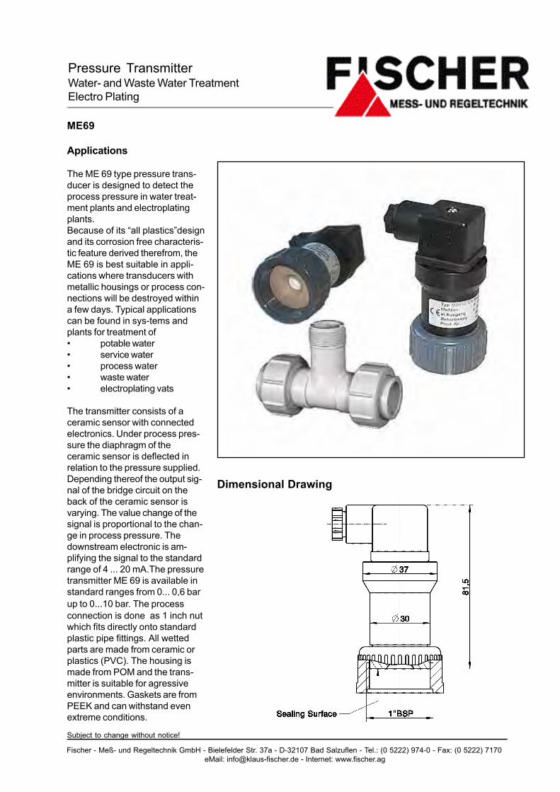
ME69
Applications
The ME 69 type pressure trans-ducer is designed to detect theprocess pressure in water treat-ment plants and electroplatingplants.Because of its �all plastics�designand its corrosion free characteris-tic feature derived therefrom, theME 69 is best suitable in appli-cations where transducers withmetallic housings or process con-nections will be destroyed withina few days. Typical applicationscan be found in sys-tems andplants for treatment of� potable water� service water� process water� waste water� electroplating vats
The transmitter consists of aceramic sensor with connectedelectronics. Under process pres-sure the diaphragm of theceramic sensor is deflected inrelation to the pressure supplied.Depending thereof the output sig-nal of the bridge circuit on theback of the ceramic sensor isvarying. The value change of thesignal is proportional to the chan-ge in process pressure. Thedownstream electronic is am-plifying the signal to the standardrange of 4 ... 20 mA.The pressuretransmitter ME 69 is available instandard ranges from 0... 0,6 barup to 0...10 bar. The processconnection is done as 1 inch nutwhich fits directly onto standardplastic pipe fittings. All wettedparts are made from ceramic orplastics (PVC). The housing ismade from POM and the trans-mitter is suitable for agressiveenvironments. Gaskets are fromPEEK and can withstand evenextreme conditions.
Subject to change without notice!
Fischer - Meß- und Regeltechnik GmbH - Bielefelder Str. 37a - D-32107 Bad Salzuflen - Tel.: (0 5222) 974-0 - Fax: (0 5222) 7170 eMail: [email protected] - Internet: www.fischer.ag
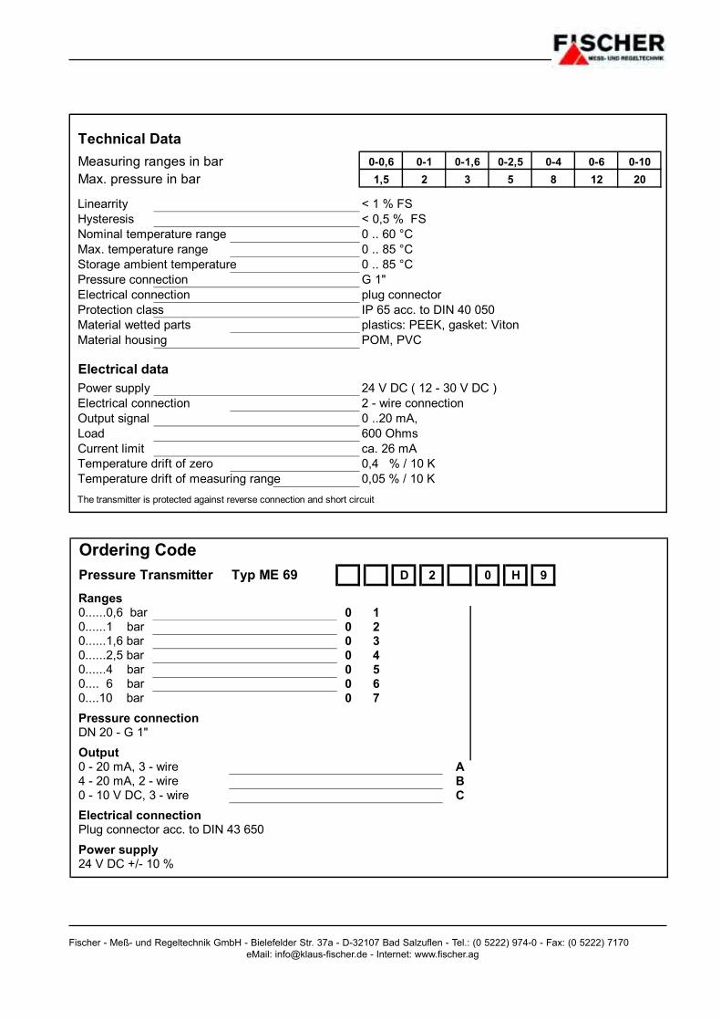
Ordering CodePressure Transmitter Typ ME 69 D 2 0 H 9
Ranges0......0,6 bar 0 10......1 bar 0 20......1,6 bar 0 30......2,5 bar 0 40......4 bar 0 50.... 6 bar 0 60....10 bar 0 7Pressure connectionDN 20 - G 1"Output0 - 20 mA, 3 - wire A4 - 20 mA, 2 - wire B0 - 10 V DC, 3 - wire CElectrical connectionPlug connector acc. to DIN 43 650Power supply24 V DC +/- 10 %
Technical DataMeasuring ranges in bar 0-0,6 0-1 0-1,6 0-2,5 0-4 0-6 0-10Max. pressure in bar 1,5 2 3 5 8 12 20
Linearrity < 1 % FSHysteresis < 0,5 % FSNominal temperature range 0 .. 60 °CMax. temperature range 0 .. 85 °CStorage ambient temperature 0 .. 85 °CPressure connection G 1" Electrical connection plug connector Protection class IP 65 acc. to DIN 40 050Material wetted parts plastics: PEEK, gasket: VitonMaterial housing POM, PVC
Electrical dataPower supply 24 V DC ( 12 - 30 V DC )Electrical connection 2 - wire connectionOutput signal 0 ..20 mA, Load 600 OhmsCurrent limit ca. 26 mATemperature drift of zero 0,4 % / 10 KTemperature drift of measuring range 0,05 % / 10 KThe transmitter is protected against reverse connection and short circuit
Pressure Transmitter
Type ME 71
General Description
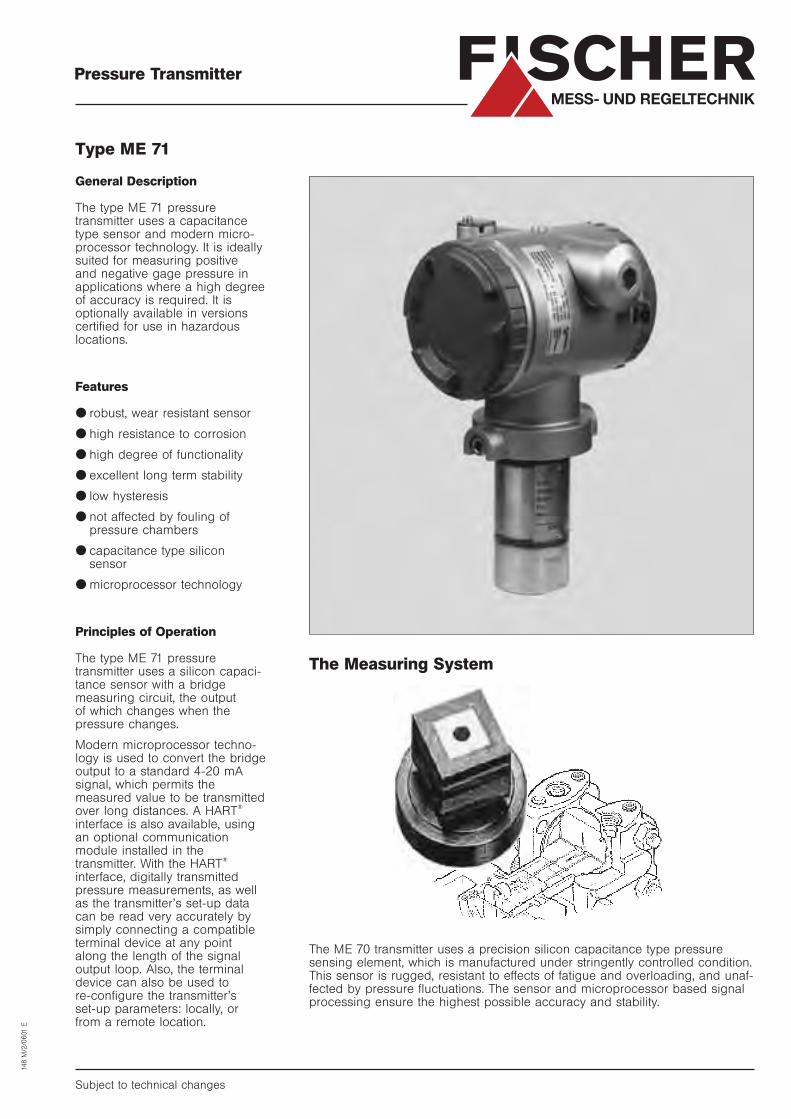
The type ME 71 pressure transmitter uses a capacitancetype sensor and modern micro-processor technology. It is ideallysuited for measuring positive and negative gage pressure inapplications where a high degree of accuracy is required. It isoptionally available in versionscertified for use in hazardouslocations.
Features
● robust, wear resistant sensor
● high resistance to corrosion
● high degree of functionality
● excellent long term stability
● low hysteresis
● not affected by fouling of pressure chambers
● capacitance type silicon sensor
● microprocessor technology
Principles of Operation
The type ME 71 pressure transmitter uses a silicon capaci-tance sensor with a bridge measuring circuit, the output of which changes when the pressure changes.
Modern microprocessor techno-logy is used to convert the bridgeoutput to a standard 4-20 mAsignal, which permits the measured value to be transmittedover long distances. A HART
®
interface is also available, usingan optional communicationmodule installed in thetransmitter. With the HART
®
interface, digitally transmittedpressure measurements, as wellas the transmitter’s set-up datacan be read very accurately bysimply connecting a compatibleterminal device at any pointalong the length of the signaloutput loop. Also, the terminaldevice can also be used to re-configure the transmitter’s set-up parameters: locally, orfrom a remote location.
Subject to technical changes
148 M
/2/0
601
E
FISCHERMESS- UND REGELTECHNIK
The Measuring System
The ME 70 transmitter uses a precision silicon capacitance type pressuresensing element, which is manufactured under stringently controlled condition.This sensor is rugged, resistant to effects of fatigue and overloading, and unaf-fected by pressure fluctuations. The sensor and microprocessor based signalprocessing ensure the highest possible accuracy and stability.

Specifications
General
Measuring ranges_ _ _ _ _ _ _ _ _ _ _ _ _ _ _ _ _ _ _ _ _ _ _ _ _ _ _ _ _ _ _ _ _ _ _ _ _ _ _ _ _ _ _ _ _ _ _ _ _ _ _ _ _ _ _ _ _ _ _ _ _ _ _ _ _ _ _ _ _ _ _ _ _ _ _ _ _ _ _ _ 0– 130 mbar to 0 – 1.3 bar. Max. static pressure: 5 bar
0–500 mbar to 0 – 5 bar. Max. static pressure: 15 bar
0–3 bar to 0 – 30 bar. Max. static pressure: 90 bar
0–10 bar to 0 – 100 bar. Max. static pressure: 150 bar
Linearity _ _ _ _ _ _ _ _ _ _ _ _ _ _ _ _ _ _ _ _ _ _ _ _ _ _ _ _ _ _ _ _ _ _ _ _ _ _ _ _ _ _ _ _ _ _ _ _ _ _ _ _ _ _ _ _ _ _ _ _ _ _ _ _ _ _ _ _ _ _ _ _ _ _ _ _ _ _ _ _ _ _ _ _ _ _ _ _ _ _ _ _ _ _ _ _ _ _ _ _ _ _ _ < 0.1%
Hysteresis _ _ _ _ _ _ _ _ _ _ _ _ _ _ _ _ _ _ _ _ _ _ _ _ _ _ _ _ _ _ _ _ _ _ _ _ _ _ _ _ _ _ _ _ _ _ _ _ _ _ _ _ _ _ _ _ _ _ _ _ _ _ _ _ _ _ _ _ _ _ _ _ _ _ _ _ _ _ _ _ _ _ _ _ _ _ _ _ _ _ _ _ _ _ _ _ _ _ < 0.1%
Temperature coefficient _ _ _ _ _ _ _ _ _ _ _ _ _ _ _ _ _ _ _ _ _ _ _ _ _ _ _ _ _ _ _ _ _ _ _ _ _ _ _ _ _ _ _ _ _ _ _ _ _ _ _ _ _ _ _ _ _ _ _ _ _ _ _ _ _ _ _ _ < 0.5% /10°K
Operating temperature ambient_ _ _ _ _ _ _ _ _ _ _ _ _ _ _ _ _ _ _ _ _ _ _ _ _ _ _ _ _ _ _ _ _ _ _ _ _ _ _ _ _ _ _ _ _ _ _ _ _ -10° to +70°C.
Operating temperature media _ _ _ _ _ _ _ _ _ _ _ _ _ _ _ _ _ _ _ _ _ _ _ _ _ _ _ _ _ _ _ _ _ _ _ _ _ _ _ _ _ _ _ _ _ _ _ _ _ _ _ _ _ 0° to +80 °C
Protection Class_ _ _ _ _ _ _ _ _ _ _ _ _ _ _ _ _ _ _ _ _ _ _ _ _ _ _ _ _ _ _ _ _ _ _ _ _ _ _ _ _ _ _ _ _ _ _ _ _ _ _ _ _ _ _ _ _ _ _ _ _ _ _ _ _ _ _ _ _ _ _ _ _ _ _ _ _ _ _ _ _ _ _ _ _ IP 67
Electrical
Supply voltage_ _ _ _ _ _ _ _ _ _ _ _ _ _ _ _ _ _ _ _ _ _ _ _ _ _ _ _ _ _ _ _ _ _ _ _ _ _ _ _ _ _ _ _ _ _ _ _ _ _ _ _ _ _ _ _ _ _ _ _ _ _ _ _ _ _ _ _ _ _ _ _ _ _ _ _ _ _ _ _ _ _ _ _ _ _ _ _ 24 V DC (15 – 30 V DC)
Power consumption _ _ _ _ _ _ _ _ _ _ _ _ _ _ _ _ _ _ _ _ _ _ _ _ _ _ _ _ _ _ _ _ _ _ _ _ _ _ _ _ _ _ _ _ _ _ _ _ _ _ _ _ _ _ _ _ _ _ _ _ _ _ _ _ _ _ _ _ _ _ _ _ _ _ _ _ Approx. 2 W
Dielectric strength _ _ _ _ _ _ _ _ _ _ _ _ _ _ _ _ _ _ _ _ _ _ _ _ _ _ _ _ _ _ _ _ _ _ _ _ _ _ _ _ _ _ _ _ _ _ _ _ _ _ _ _ _ _ _ _ _ _ _ _ _ _ _ _ _ _ _ _ _ _ _ _ _ _ _ _ _ _ _ _ 500 V AC
Output signal _ _ _ _ _ _ _ _ _ _ _ _ _ _ _ _ _ _ _ _ _ _ _ _ _ _ _ _ _ _ _ _ _ _ _ _ _ _ _ _ _ _ _ _ _ _ _ _ _ _ _ _ _ _ _ _ _ _ _ _ _ _ _ _ _ _ _ _ _ _ _ _ _ _ _ _ _ _ _ _ _ _ _ _ _ _ _ _ _ _ _ 4 – 20 mA. Optional: HART®
interface, using
communication module (option -K: see ordering code)
Output load_ _ _ _ _ _ _ _ _ _ _ _ _ _ _ _ _ _ _ _ _ _ _ _ _ _ _ _ _ _ _ _ _ _ _ _ _ _ _ _ _ _ _ _ _ _ _ _ _ _ _ _ _ _ _ _ _ _ _ _ _ _ _ _ _ _ _ _ _ _ _ _ _ _ _ _ _ _ _ _ _ _ _ _ _ _ _ _ _ _ _ _ _ _ _ Max. 600 Ohm (minimum 250 Ohms with communication
module installed)
Output current limit _ _ _ _ _ _ _ _ _ _ _ _ _ _ _ _ _ _ _ _ _ _ _ _ _ _ _ _ _ _ _ _ _ _ _ _ _ _ _ _ _ _ _ _ _ _ _ _ _ _ _ _ _ _ _ _ _ _ _ _ _ _ _ _ _ _ _ _ _ _ _ _ _ _ _ _ _ 25 mA
Built-in display (optional) Analog display with 0-100% scale
Digital display (only with communication Module
option -K installed)
Connections
Electrical connections_ _ _ _ _ _ _ _ _ _ _ _ _ _ _ _ _ _ _ _ _ _ _ _ _ _ _ _ _ _ _ _ _ _ _ _ _ _ _ _ _ _ _ _ _ _ _ _ _ _ _ _ _ _ _ _ _ _ _ _ _ _ _ _ _ _ _ _ _ _ _ _ Internal terminal block
Pressure connection_ _ _ _ _ _ _ _ _ _ _ _ _ _ _ _ _ _ _ _ _ _ _ _ _ _ _ _ _ _ _ _ _ _ _ _ _ _ _ _ _ _ _ _ _ _ _ _ _ _ _ _ _ _ _ _ _ _ _ _ _ _ _ _ _ _ _ _ _ _ _ _ _ _ _ 1/2" NPT(F) threaded socket
Materials
Parts in contact with media _ _ _ _ _ _ _ _ _ _ _ _ _ _ _ _ _ _ _ _ _ _ _ _ _ _ _ _ _ _ _ _ _ _ _ _ _ _ _ _ _ _ _ _ _ _ _ _ _ _ _ _ _ _ _ _ _ _ _ Stainless steel 316 L (1. 4404)
Seals _ _ _ _ _ _ _ _ _ _ _ _ _ _ _ _ _ _ _ _ _ _ _ _ _ _ _ _ _ _ _ _ _ _ _ _ _ _ _ _ _ _ _ _ _ _ _ _ _ _ _ _ _ _ _ _ _ _ _ _ _ _ _ _ _ _ _ _ _ _ _ _ _ _ _ _ _ _ _ _ _ _ _ _ _ _ _ _ _ _ _ _ _ _ _ _ _ _ _ _ _ _ _ _ _ _ _ _ _ Viton. optional: teflon
Electronics housing_ _ _ _ _ _ _ _ _ _ _ _ _ _ _ _ _ _ _ _ _ _ _ _ _ _ _ _ _ _ _ _ _ _ _ _ _ _ _ _ _ _ _ _ _ _ _ _ _ _ _ _ _ _ _ _ _ _ _ _ _ _ _ _ _ _ _ _ _ _ _ _ _ _ _ _ _ Aluminium (surface coated)
CE marking _ _ _ _ _ _ _ _ _ _ _ _ _ _ _ _ _ _ _ _ _ _ _ _ _ _ _ _ _ _ _ _ _ _ _ _ _ _ _ _ _ _ _ _ _ _ _ _ _ _ _ _ _ _ _ _ _ _ _ _ _ _ _ _ _ _ _ _ _ _ _ _ _ _ _ _ _ _ _ _ _ _ _ _ _ _ _ _ _ _ _ _ The ME 71 transmitter carries the CE mark,
and complies with EMV specifications
EN 50082–1 and EN 50082–2
FISCHERMESS- UND REGELTECHNIK

FISCHERMESS- UND REGELTECHNIK
Dimensional Drawings
Electrical connections
Locking clamp(only for explosion-proof version)
Cable entry for models whichhave Ordering Code„S, V, W“, in fourth place
9,0 mmholes x 2
Adjusting screw for output signal
„B“Cable entry
„C“Cable entry
„D“Adaptor (optional)
„A“Pressure connection
Explosion-proof cable gland, suppliedwith explosion-proof transmitterversions.(Cable diameter should be 11 mm)
108
Up
Down
∅80
170
110
50
70
85
196 27
88
With external display(optional)
Mounting pipeJIS 50A (2B)
U-bolt (M8)
51 71 (27)
∅80
214
G
Earthing terminal(both sides).See Table 1
+ –
+ – CK+ CK–
H
35
J
Hexagonal socket
head cap screw
35

FISCHERMESS- UND REGELTECHNIK
Type ME 71 V O Y O
Communication Module
Without communications module . . . . .T HWith communications module . . . . . . . .T K
Electrical connection: PG 13.5
Range
0– 130 mbar to … 1.3 bar . . . . . . . . . . . . . . . . . .T 1 V0– 0.5 bar to … 5 bar . . . . . . . . . . . . . . . . . .T 2 V0– 3 bar to … 30 bar . . . . . . . . . . . . . . . . . .T 3 V0– 10 bar to …100 bar . . . . . . . . . . . . . . . . . .T 4 V
Display
Without display . . . . . . . . . . . . . . . . . . . . . . . . . . . . . . . . . . . . . .T AWith analog display scale 0 – 100% . . . . . . . . . . . . . . . . . . . . . . .T BWith digital display (only with option -K installed) . . . . . . . . . . . .T L
Hazardous location approval
Not approved for hazardous locations . . . . . . . . . . . . . . . . . . . . . . . . . .T AIntrinsically safe per E Ex i a II C T4/T5 . . . . . . . . . . . . . . . . . . . . . . . . .T KExplosion-proof per Ex d II C T5/T6 . . . . . . . . . . . . . . . . . . . . . . . . . . . .T X
Mounting bracket kit
Without mounting bracket kit . . . . . . . . . . . . . . . . . . . . . . . . . . . . . . . . . . . . . . .T AWith mounting bracket kit (stainless steel) . . . . . . . . . . . . . . . . . . . . . . . . . . . .T C
Instrument tag plate
Without tag plate . . . . . . . . . . . . . . . . . . . . . . . . . . . . . . . . . . . . . . . . . . . . . . . . . . . . .T YStainless tag plate with customer application data . . . . . . . . . . . . . . . . . . . . . . . . . . .T B
Sensor filling liquid
Silicone oil . . . . . . . . . . . . . . . . . . . . . . . . . . . . . . . . . . . . . . . . . . . . . . . . . . . . . . . . . . . . . . .T YFluorinated oil for oxygen service . . . . . . . . . . . . . . . . . . . . . . . . . . . . . . . . . . . . . . . . . . . . .T A
Pressure connection: 1/4 NPT inside 7/16.UNF
Ordering Code
r r r r r r r
Fischer · Meß- und Regeltechnik GmbH · Bielefelder Str. 37a · D-32107 Bad Salzuflen · Tel. (0 52 22) 9 74-0 · Fax (0 52 22) 7170eMail: [email protected] · Internet: www.fischer.ag
Absolute PressureTransmitter
Contact Pressure Gauge(for heavy measuring conditions)
Type MS 11
Application
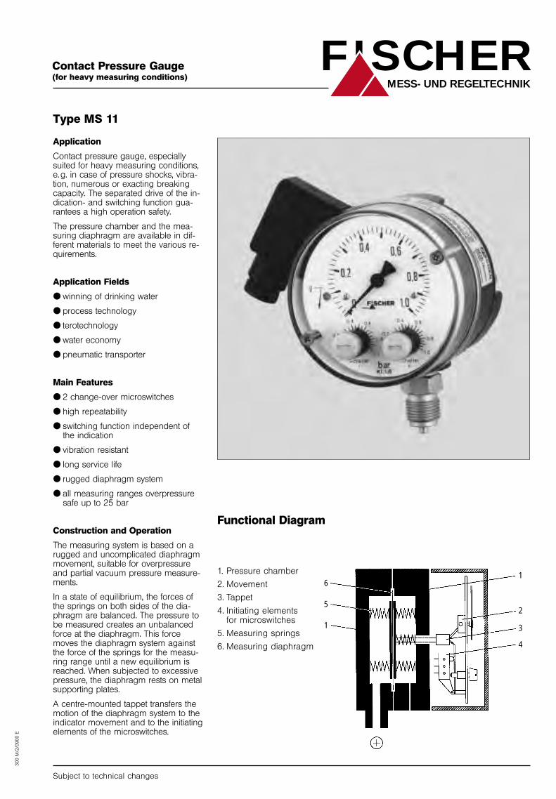
Contact pressure gauge, especiallysuited for heavy measuring conditions,e. g. in case of pressure shocks, vibra-tion, numerous or exacting breakingcapacity. The separated drive of the in-dication- and switching function gua-rantees a high operation safety.
The pressure chamber and the mea-suring diaphragm are available in dif-ferent materials to meet the various re-quirements.
Application Fields
● winning of drinking water
● process technology
● terotechnology
● water economy
● pneumatic transporter
Main Features
● 2 change-over microswitches
● high repeatability
● switching function independent ofthe indication
● vibration resistant
● long service life
● rugged diaphragm system
● all measuring ranges overpressuresafe up to 25 bar
Construction and Operation
The measuring system is based on arugged and uncomplicated diaphragmmovement, suitable for overpressureand partial vacuum pressure measure-ments.
In a state of equilibrium, the forces ofthe springs on both sides of the dia-phragm are balanced. The pressure tobe measured creates an unbalancedforce at the diaphragm. This forcemoves the diaphragm system againstthe force of the springs for the measu-ring range until a new equilibrium isreached. When subjected to excessivepressure, the diaphragm rests on metalsupporting plates.
A centre-mounted tappet transfers themotion of the diaphragm system to theindicator movement and to the initiatingelements of the microswitches.
Subject to technical changes
Functional Diagram
300 M
/2/0
900 E
FISCHERMESS- UND REGELTECHNIK
6
5
1
1
2
3
4
1. Pressure chamber
2. Movement
3. Tappet
4. Initiating elementsfor microswitches
5. Measuring springs
6. Measuring diaphragm
Technical Data
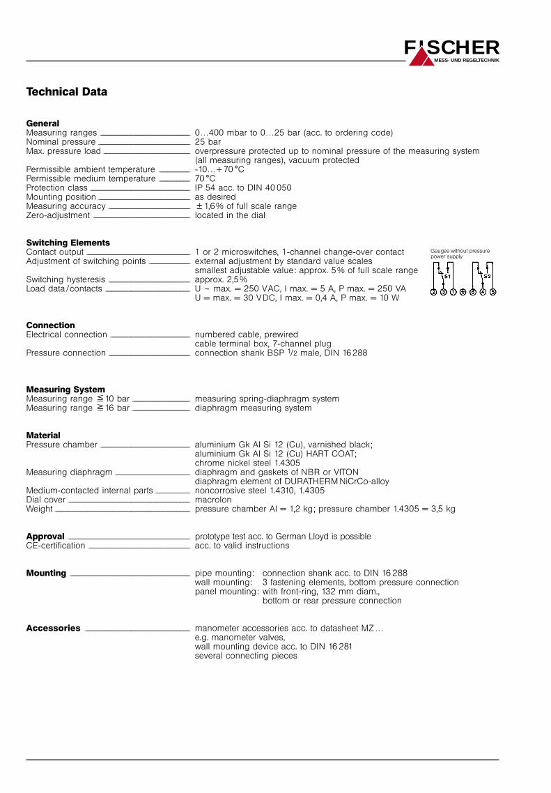
GeneralMeasuring ranges _ _ _ _ _ _ _ _ _ _ _ _ _ _ _ _ _ _ _ _ _ _ _ _ _ _ _ _ _ _ _ _ _ _ _ _ _ _ _ _ _ _ _ _ _ _ _ _ _ _ _ _ _ 0…400 mbar to 0…25 bar (acc. to ordering code)Nominal pressure _ _ _ _ _ _ _ _ _ _ _ _ _ _ _ _ _ _ _ _ _ _ _ _ _ _ _ _ _ _ _ _ _ _ _ _ _ _ _ _ _ _ _ _ _ _ _ _ _ _ _ _ _ _ 25 barMax. pressure load _ _ _ _ _ _ _ _ _ _ _ _ _ _ _ _ _ _ _ _ _ _ _ _ _ _ _ _ _ _ _ _ _ _ _ _ _ _ _ _ _ _ _ _ _ _ _ _ _ _ _ overpressure protected up to nominal pressure of the measuring system
(all measuring ranges), vacuum protectedPermissible ambient temperature _ _ _ _ _ _ _ _ _ _ _ _ _ _ _ _ _ _ -10…+ 70 °CPermissible medium temperature _ _ _ _ _ _ _ _ _ _ _ _ _ _ _ _ _ _ 70 °CProtection class _ _ _ _ _ _ _ _ _ _ _ _ _ _ _ _ _ _ _ _ _ _ _ _ _ _ _ _ _ _ _ _ _ _ _ _ _ _ _ _ _ _ _ _ _ _ _ _ _ _ _ _ _ _ _ _ _ _ _ IP 54 acc. to DIN 40 050Mounting position _ _ _ _ _ _ _ _ _ _ _ _ _ _ _ _ _ _ _ _ _ _ _ _ _ _ _ _ _ _ _ _ _ _ _ _ _ _ _ _ _ _ _ _ _ _ _ _ _ _ _ _ _ _ as desiredMeasuring accuracy _ _ _ _ _ _ _ _ _ _ _ _ _ _ _ _ _ _ _ _ _ _ _ _ _ _ _ _ _ _ _ _ _ _ _ _ _ _ _ _ _ _ _ _ _ _ _ _ 81,6% of full scale rangeZero-adjustment _ _ _ _ _ _ _ _ _ _ _ _ _ _ _ _ _ _ _ _ _ _ _ _ _ _ _ _ _ _ _ _ _ _ _ _ _ _ _ _ _ _ _ _ _ _ _ _ _ _ _ _ _ _ _ _ _ located in the dial
Switching ElementsContact output _ _ _ _ _ _ _ _ _ _ _ _ _ _ _ _ _ _ _ _ _ _ _ _ _ _ _ _ _ _ _ _ _ _ _ _ _ _ _ _ _ _ _ _ _ _ _ _ _ _ _ _ _ _ _ _ _ _ _ _ _ 1 or 2 microswitches, 1-channel change-over contactAdjustment of switching points _ _ _ _ _ _ _ _ _ _ _ _ _ _ _ _ _ _ _ _ _ _ _ _ external adjustment by standard value scales
smallest adjustable value: approx. 5% of full scale rangeSwitching hysteresis _ _ _ _ _ _ _ _ _ _ _ _ _ _ _ _ _ _ _ _ _ _ _ _ _ _ _ _ _ _ _ _ _ _ _ _ _ _ _ _ _ _ _ _ _ _ _ _ approx. 2,5%Load data /contacts _ _ _ _ _ _ _ _ _ _ _ _ _ _ _ _ _ _ _ _ _ _ _ _ _ _ _ _ _ _ _ _ _ _ _ _ _ _ _ _ _ _ _ _ _ _ _ _ _ _ U ~ max. = 250 VAC, I max. = 5 A, P max. = 250 VA
U = max. = 30 VDC, I max. = 0,4 A, P max. = 10 W
ConnectionElectrical connection _ _ _ _ _ _ _ _ _ _ _ _ _ _ _ _ _ _ _ _ _ _ _ _ _ _ _ _ _ _ _ _ _ _ _ _ _ _ _ _ _ _ _ _ _ _ _ numbered cable, prewired
cable terminal box, 7-channel plugPressure connection _ _ _ _ _ _ _ _ _ _ _ _ _ _ _ _ _ _ _ _ _ _ _ _ _ _ _ _ _ _ _ _ _ _ _ _ _ _ _ _ _ _ _ _ _ _ _ _ connection shank BSP 1/2 male, DIN 16 288
Measuring SystemMeasuring range &10 bar _ _ _ _ _ _ _ _ _ _ _ _ _ _ _ _ _ _ _ _ _ _ _ _ _ _ _ _ _ _ _ _ _ _ measuring spring-diaphragm systemMeasuring range 716 bar _ _ _ _ _ _ _ _ _ _ _ _ _ _ _ _ _ _ _ _ _ _ _ _ _ _ _ _ _ _ _ _ _ _ diaphragm measuring system
MaterialPressure chamber _ _ _ _ _ _ _ _ _ _ _ _ _ _ _ _ _ _ _ _ _ _ _ _ _ _ _ _ _ _ _ _ _ _ _ _ _ _ _ _ _ _ _ _ _ _ _ _ _ _ _ _ _ aluminium Gk Al Si 12 (Cu), varnished black;
aluminium Gk Al Si 12 (Cu) HART COAT;chrome nickel steel 1.4305
Measuring diaphragm _ _ _ _ _ _ _ _ _ _ _ _ _ _ _ _ _ _ _ _ _ _ _ _ _ _ _ _ _ _ _ _ _ _ _ _ _ _ _ _ _ _ _ _ diaphragm and gaskets of NBR or VITONdiaphragm element of DURATHERM NiCrCo-alloy
Medium-contacted internal parts _ _ _ _ _ _ _ _ _ _ _ _ _ _ _ _ _ _ _ _ noncorrosive steel 1.4310, 1.4305Dial cover _ _ _ _ _ _ _ _ _ _ _ _ _ _ _ _ _ _ _ _ _ _ _ _ _ _ _ _ _ _ _ _ _ _ _ _ _ _ _ _ _ _ _ _ _ _ _ _ _ _ _ _ _ _ _ _ _ _ _ _ _ _ _ _ _ _ _ _ _ _ _ _ macrolonWeight _ _ _ _ _ _ _ _ _ _ _ _ _ _ _ _ _ _ _ _ _ _ _ _ _ _ _ _ _ _ _ _ _ _ _ _ _ _ _ _ _ _ _ _ _ _ _ _ _ _ _ _ _ _ _ _ _ _ _ _ _ _ _ _ _ _ _ _ _ _ _ _ _ _ _ _ _ _ _ _ pressure chamber Al = 1,2 kg; pressure chamber 1.4305 = 3,5 kg
Approval ________________________________________________________________________________________ prototype test acc. to German Lloyd is possibleCE-certification _ _ _ _ _ _ _ _ _ _ _ _ _ _ _ _ _ _ _ _ _ _ _ _ _ _ _ _ _ _ _ _ _ _ _ _ _ _ _ _ _ _ _ _ _ _ _ _ _ _ _ _ _ _ _ _ _ _ _ _ acc. to valid instructions
Mounting _ _ _ _ _ _ _ _ _ _ _ _ _ _ _ _ _ _ _ _ _ _ _ _ _ _ _ _ _ _ _ _ _ _ _ _ _ _ _ _ _ _ _ _ _ _ _ _ _ _ _ _ _ _ _ _ _ _ _ _ _ _ _ _ _ _ _ _ _ _ _ pipe mounting: connection shank acc. to DIN 16 288_ _ _ _ _ _ _ _ _ _ _ _ _ _ _ _ _ _ _ _ _ wall mounting: 3 fastening elements, bottom pressure connection_ _ _ _ _ _ _ _ _ _ _ _ _ _ _ _ _ _ _ _ _ panel mounting: with front-ring, 132 mm diam.,_ _ _ _ _ _ _ _ _ _ _ _ _ _ _ _ _ _ _ _ _ bottom or rear pressure connection
Accessories _ _ _ _ _ _ _ _ _ _ _ _ _ _ _ _ _ _ _ _ _ _ _ _ _ _ _ _ _ _ _ _ _ _ _ _ _ _ _ _ _ _ _ _ _ _ _ _ _ _ _ _ _ _ _ _ _ _ _ _ _ _ manometer accessories acc. to datasheet MZ…e.g. manometer valves,wall mounting device acc. to DIN 16 281several connecting pieces
FISCHERMESS- UND REGELTECHNIK
Gauges without pressurepower supply
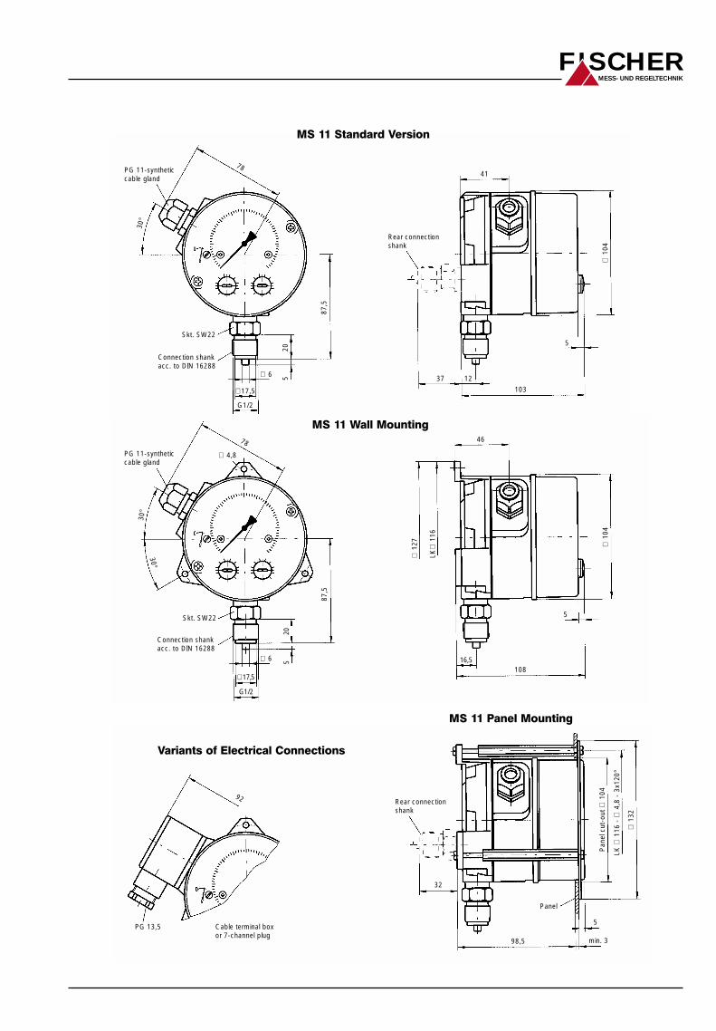
PG 11-syntheticcable gland
Skt. SW22
Connection shankacc. to DIN 16288
Rear connectionshank
41
∅10
4
87,5
78
30°
520
∅17,5
G1/2
∅ 6
103
1237
5
PG 13,5 Cable terminal boxor 7-channel plug
Rear connectionshank
92
∅13
2
LK ∅
116
- ∅
4,8
- 3x
120°
Pan
el c
ut-o
ut ∅
104
Panel
98,5
32
5
min. 3
PG 11-syntheticcable gland
Skt. SW22
Connection shankacc. to DIN 16288
46
∅10
4
∅12
7
∅ 6
∅ 4,8
∅ 17,5
16,5
5
G1/2
205
LK∅
116
78
30°
30°
108
87,5
FISCHERMESS- UND REGELTECHNIK
MS 11 Standard Version
MS 11 Wall Mounting
MS 11 Panel Mounting
Variants of Electrical Connections
r
FISCHERMESS- UND REGELTECHNIK
r r r rr
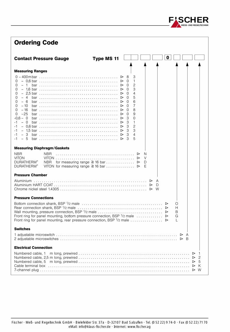
Ordering Code
Type MS 11 0Contact Pressure Gauge
Measuring Ranges
0 – 400mbar . . . . . . . . . . . . . . . . . . . . . . . . . . . . . . . . . . . . . . . T 8 3
0 – 0,6 bar . . . . . . . . . . . . . . . . . . . . . . . . . . . . . . . . . . . . . . . T 0 1
0 – 1 bar . . . . . . . . . . . . . . . . . . . . . . . . . . . . . . . . . . . . . . . T 0 2
0 – 1,6 bar . . . . . . . . . . . . . . . . . . . . . . . . . . . . . . . . . . . . . . . T 0 3
0 – 2,5 bar . . . . . . . . . . . . . . . . . . . . . . . . . . . . . . . . . . . . . . . T 0 4
0 – 4 bar . . . . . . . . . . . . . . . . . . . . . . . . . . . . . . . . . . . . . . . T 0 5
0 – 6 bar . . . . . . . . . . . . . . . . . . . . . . . . . . . . . . . . . . . . . . . T 0 6
0 – 10 bar . . . . . . . . . . . . . . . . . . . . . . . . . . . . . . . . . . . . . . . T 0 7
0 – 16 bar . . . . . . . . . . . . . . . . . . . . . . . . . . . . . . . . . . . . . . . T 0 8
0 –25 bar . . . . . . . . . . . . . . . . . . . . . . . . . . . . . . . . . . . . . . . T 0 9
-0,6 – 0 bar . . . . . . . . . . . . . . . . . . . . . . . . . . . . . . . . . . . . . . . T 3 0
-1 – 0 bar . . . . . . . . . . . . . . . . . . . . . . . . . . . . . . . . . . . . . . . T 3 1
-1 – 0,6 bar . . . . . . . . . . . . . . . . . . . . . . . . . . . . . . . . . . . . . . . T 3 2
-1 – 1,5 bar . . . . . . . . . . . . . . . . . . . . . . . . . . . . . . . . . . . . . . . T 3 3
-1 – 3 bar . . . . . . . . . . . . . . . . . . . . . . . . . . . . . . . . . . . . . . . T 3 4
-1 – 5 bar . . . . . . . . . . . . . . . . . . . . . . . . . . . . . . . . . . . . . . . T 3 5
Measuring Diaphragm/Gaskets
NBR NBR . . . . . . . . . . . . . . . . . . . . . . . . . . . . . . . . . . . . . . . T N
VITON VITON . . . . . . . . . . . . . . . . . . . . . . . . . . . . . . . . . . . . . . . T V
DURATHERM®
NBR for measuring range 716 bar . . . . . . . . . . . . . . T D
DURATHERM®
VITON for measuring range 716 bar . . . . . . . . . . . . . . T E
Pressure Chamber
Aluminium . . . . . . . . . . . . . . . . . . . . . . . . . . . . . . . . . . . . . . . . . . . . . . . . . . . . . . . . T A
Aluminium HART COAT . . . . . . . . . . . . . . . . . . . . . . . . . . . . . . . . . . . . . . . . . . . . . . T D
Chrome nickel steel 1.4305 . . . . . . . . . . . . . . . . . . . . . . . . . . . . . . . . . . . . . . . . . . . T W
Pressure Connections
Bottom connection shank, BSP 1/2 male . . . . . . . . . . . . . . . . . . . . . . . . . . . . . . . . . . . . . . . . T O
Rear connection shank, BSP 1/2 male . . . . . . . . . . . . . . . . . . . . . . . . . . . . . . . . . . . . . . . . . . T H
Wall mounting, pressure connection, BSP 1/2 male . . . . . . . . . . . . . . . . . . . . . . . . . . . . . . . . T B
Front ring for panel mounting, bottom pressure connection, BSP 1/2 male . . . . . . . . . . . . . T G
Front ring for panel mounting, rear pressure connection, BSP 1/2 male . . . . . . . . . . . . . . . . T L
Switches
1 adjustable microswitch . . . . . . . . . . . . . . . . . . . . . . . . . . . . . . . . . . . . . . . . . . . . . . . . . . . . . . . . . . . . T A
2 adjustable microswitches . . . . . . . . . . . . . . . . . . . . . . . . . . . . . . . . . . . . . . . . . . . . . . . . . . . . . . . . . . T B
Electrical Connection
Numbered cable, 1 m long, prewired . . . . . . . . . . . . . . . . . . . . . . . . . . . . . . . . . . . . . . . . . . . . . . . . . . . . . . . T 1
Numbered cable, 2,5 m long, prewired . . . . . . . . . . . . . . . . . . . . . . . . . . . . . . . . . . . . . . . . . . . . . . . . . . . . . . . T 2
Numbered cable, 5 m long, prewired . . . . . . . . . . . . . . . . . . . . . . . . . . . . . . . . . . . . . . . . . . . . . . . . . . . . . . . T 5
Cable terminal box . . . . . . . . . . . . . . . . . . . . . . . . . . . . . . . . . . . . . . . . . . . . . . . . . . . . . . . . . . . . . . . . . . . . . . T K
7-channel plug . . . . . . . . . . . . . . . . . . . . . . . . . . . . . . . . . . . . . . . . . . . . . . . . . . . . . . . . . . . . . . . . . . . . . . . . . . T W
Fischer · Meß- und Regeltechnik GmbH · Bielefelder Str. 37a · D-32107 Bad Salzuflen · Tel. (0 52 22) 9 74-0 · Fax (0 52 22) 7170eMail: [email protected] · Internet: www.fischer.ag