d5.1 – rapid prototyping environment · 2020-01-13 · aal-2009-2-049 alias d5.1 v 2.00 file:...
TRANSCRIPT

D5.1 – Rapid Prototyping Environment
Project arconym: ALIAS Project name: Adaptable Ambient Living Assistant
Strategic Objective: ICT based solutions for Advancement of Social Interaction of Elderly People
Project number: AAL-2009-2-049
Project Duration: July, 1st 2010 – Juni, 30th 2013 (36months)
Co-ordinator: Prof. Dr. Frank Wallhoff
Partners: Technische Universität München Technische Universität Ilmenau Metralabs GmbH Cognesys GmbH EURECOM Guger Technologies Fraunhofer Gesellschaft pme Familenservice YOUSE GbR
D5.1
Literaturverzeichnis Im aktuellen Dokument sind keine
Quellen vorhanden.
X.X
Version: 2.00
Date: 23/2/2010
Author: Hintermüller
Dissemination status: PU
This project is co-funded by the Ambient Assisted Living (AAL) Joint
programme, by the German BMBF, the French ANR, the Austrian BMVIT.

AAL-2009-2-049 ALIAS D5.1 v 2.00
File: D51_RapidPrototypingEnvironment_V2-01032011-GTEC-EB-CLEAN Page 1 of 10
Del 5.1 Executive Summary
This document describes the rapid prototyping environment for the BCI control system. In this document we first describe the hardware consisting of the EEG cap, the active electrodes, the preamplifier g.GAMMAbox and the bio-signal amplifier g.Mobilab+ which is connected via Bluetooth interface to the laptop on which the rapid prototyping software environment is installed. The second part of this document describes the software issues. The main part of the software for the rapid prototyping environment is the SIMULINK driver which allows an easy data acquisition and data analysis using MATLAB/SIMULINK.
Dissemination Level of this deliverable (Source: Alias Technical Annex p20 & 22)
PU Public
Nature of this deliverable (Source: Alias Technical Annex p20 & 22)
R&P Report and Prototype
Due date of deliverable 31/12/2010
Actual submission date 23/02/2010
Evidence of delivery Device available
Authorisation
No. Action Company/Name Date
1 Prepared GTEC 23/02/2010
Disclaimer: The information in this document is subject to change without notice. Company or product names mentioned in this document may be trademarks or registered trademarks of their respective companies.
AAL-2009-2-049 ALIAS D5.1 v 2.00
File: D51_RapidPrototypingEnvironment_V2-01032011-GTEC-EB-CLEAN Page 2 of 10
Contents
Introduction -------------------------------------------------------------------------------------------------------------------- 3
Software requirements for the rapid prototyping environment----------------------------------------------- 4
Rapid Prototyping System -------------------------------------------------------------------------------------------------- 4
Hardware description ---------------------------------------------------------------------------------------------------- 5
EEG cap and EEG cap montage:------------------------------------------------------------------------------------- 5
Active electrodes and preamplifier -------------------------------------------------------------------------------- 5
Biosignal amplifier: g. Mobilab+ EEG ------------------------------------------------------------------------------ 7
Recording setup -------------------------------------------------------------------------------------------------------- 8
Software describtion------------------------------------------------------------------------------------------------------ 8
System Architecture --------------------------------------------------------------------------------------------------- 9
Using the Rapid Prototyping in MATLAB/Simulink ------------------------------------------------------------- 9
Conclusion and Outlook --------------------------------------------------------------------------------------------------- 10

AAL-2009-2-049 ALIAS D5.1 v 2.00
File: D51_RapidPrototypingEnvironment_V2-01032011-GTEC-EB-CLEAN Page 3 of 10
Introduction The principal goal of ALIAS is to develop a mobile robot system that interacts with elderly
users. The system is intended to monitor the users and provide them with cognitive
assistance and create connections to their family and friends. The robot will offer several
different control interfaces, a touch screen, speech input and an EEG based BCI interface,
which has to be adopted and enabled for the dedicated applications and components of the
ALIAS robot system. To this end for a fast progress a rapid prototyping environment is
necessary. Figure 1 shows the difference between a traditional development process and a
rapid prototyping development process. While in the traditional approach the algorithm has
to be implemented on a software environment running on a hardware to be designed, with
the rapid prototyping approach the developed algorithm can be directly implemented on the
target system without further software and hardware development steps.
A rapid prototyping environment for ALIAS has to allow:
measurements and online analysis of EEG data
measurements and online analysis of additional physiological data
sending and receiving commands of the components and systems of the robotic
platform developed in ALIAS
In its first version, as it is distributed by M6, the rapid prototyping is designed as EEG/BCI
processing system only. The system will be able to acquire EEG data and analyze data in real-
time, identify the command which was selected by the user and send the corresponding
command string to the other components of ALIAS like the dialog manager, developed in
task T3.3, for execution. The system is based on MATLAB/Simulink for fast design iterations
and will be installed at specific partner sites developing the ALIAS specific components of the
ALIAS robot.
In a later stage of the project the rapid prototyping environment will be extended to record
other bio-signals like ECG, respiration, galvanic skin response etc. and extract related
features and parameters such as heart rate (HR), heart rate variability, respiration rate, etc.
Therefore in Simulink (see e.g.Figure 2) the driver for the portable bio-signal amplifier and
Figure 1: Comparison of a traditional development approach and a rapid prototyping process

AAL-2009-2-049 ALIAS D5.1 v 2.00
File: D51_RapidPrototypingEnvironment_V2-01032011-GTEC-EB-CLEAN Page 4 of 10
the interfaces to the robotic platform used in ALIAS will be available as block sets which
allow the partners a fast implementation of real time BCI control strategies.
For measuring the EEG g.GAMMAcaps with locations according to the 10/20 system will be
used. Due to the superior data quality which can be achieved, active electrodes will be
applied within the project having in mind that the users will move during measurements.
Additionally the application of the electrodes is very fast.
Guger Technologies OG supplies the partners with the hardware consisting of
EEG cap with active electrodes
Preamplifier for the active electrodes
g.Mobilab Biosignal amplifier
and the software (except the licenses for Matlab® and Simulink®) as described below.
Software requirements for the rapid prototyping environment
For running the rapid prototyping environment the following software requirements are
necessary:
Matlab Licence: supported Matlab version: R2009b: Following toolbox is mandatory:
o Signal Processing Toolbox
Simulink Licence: supported Simulink version: R2009b: Following blockset is
mandatory:
o Signal processing Block Set
Rapid Prototyping System In the following the rapid prototyping system will be described. Therefore the description is
separated into hard- and software and in how to use the rapid prototyping environment at
the end of the section.
Figure 2: Rapid prototyping environment under Matlab/Simulink

AAL-2009-2-049 ALIAS D5.1 v 2.00
File: D51_RapidPrototypingEnvironment_V2-01032011-GTEC-EB-CLEAN Page 5 of 10
Hardware description
EEG cap and EEG cap montage:
EEG electrodes are normally distributed on the scalp according to the international
10-20 electrode system. Therefore, the distance from the Inion (see Figure 3) to the
Nasion is first measured. Then, electrode Cz on the vertex of the cap is shifted
exactly to 50% of this distance, as indicated on the left picture of Figure 3. However in
ALIAS the recently developed g.GAMMAcap as shown in the right picture of Figure 3
will be used. This cap is able to work with active ring electrodes.
The applied system is a single electrode system with the following main properties:
Advantage: if one electrode breaks down it can be removed immediately.
Advantage: every electrode montage can be realized easily.
Disadvantage: all electrodes must be connected separately each time.
Active electrodes and preamplifier
For the measurements within the ALIAS project active Ag/AgCl ring electrodes
(g.LADYbird) as shown in Figure 4 are applied since they show good performance for
the application intended to be used. Active electrodes have a pre-amplifier
(g.GAMMAbox; see Figure 5) with gain 1 inside the electrode which makes the
electrode less sensitive against environmental noise such as power line interference
and cable movements. Because of this fact, active electrodes also work if the
electrode-skin impedance is higher than for passive electrodes (should be below 10
kOhm). Active electrodes have system connectors to supply the electronic
components with power. It is possible to use them for measuring EEG, EOG and
EMG. In this cases a double sided adhesive washers can be applied to fix the
electrodes to the skin.
For further EMG measurements passive electrodes consisting of the disposable electrode
shown in Figure 6 and the ECG electrode cables with clip lead shown in Figure 7 can be
applied. The ECG electrode cable is fitted with a 1.5mm medical safety connector which can
directly be plugged into the amplifier.
Figure 3: left: EEG cap montage; right: g.GAMMAcap with active electrodes

AAL-2009-2-049 ALIAS D5.1 v 2.00
File: D51_RapidPrototypingEnvironment_V2-01032011-GTEC-EB-CLEAN Page 6 of 10
Figure 4: Active ring Ag/AgCl electrodes
Figure 5: g.GAMMAbox for active electrodes
Figure 6: Disposable electrodes
Figure 7: Electrode cable with clip lead
AAL-2009-2-049 ALIAS D5.1 v 2.00
File: D51_RapidPrototypingEnvironment_V2-01032011-GTEC-EB-CLEAN Page 7 of 10
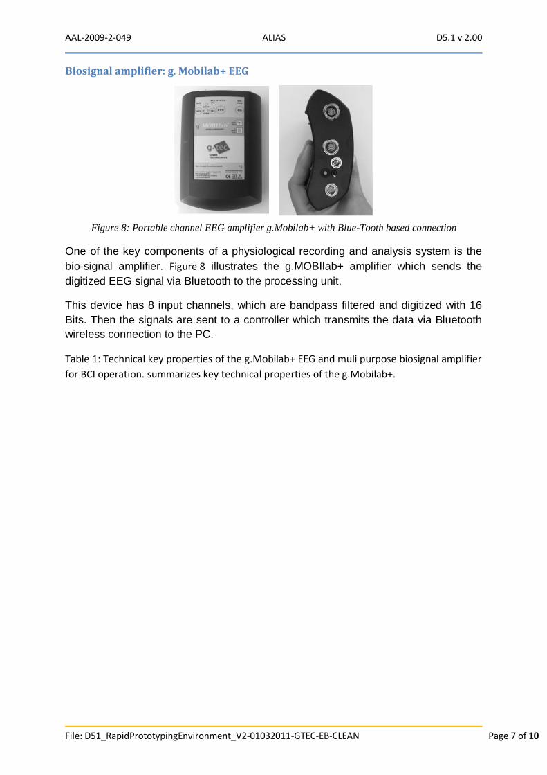
Biosignal amplifier: g. Mobilab+ EEG
One of the key components of a physiological recording and analysis system is the
bio-signal amplifier. Figure 8 illustrates the g.MOBIlab+ amplifier which sends the
digitized EEG signal via Bluetooth to the processing unit.
This device has 8 input channels, which are bandpass filtered and digitized with 16
Bits. Then the signals are sent to a controller which transmits the data via Bluetooth
wireless connection to the PC.
Table 1: Technical key properties of the g.Mobilab+ EEG and muli purpose biosignal amplifier
for BCI operation. summarizes key technical properties of the g.Mobilab+.
Figure 8: Portable channel EEG amplifier g.Mobilab+ with Blue-Tooth based connection

AAL-2009-2-049 ALIAS D5.1 v 2.00
File: D51_RapidPrototypingEnvironment_V2-01032011-GTEC-EB-CLEAN Page 8 of 10
Recording setup
The electrodes can be mounted to any position of the cap. The electrodes are then
connected to the g.GAMMAbox:
IMPORTANT: The ground electrode must not be exchanged with the reference electrode!
The g.GAMMAbox is then connected via the g.GAMMAbox connector to the g.Mobilab+,
which is further connected to the laptop on which the required software is installed.
Software describtion
The signal flow oriented Simulink which runs under MATLAB allows people to create
block diagrams for signal processing. Therefore, a hardware-interrupt driven device
driver was implemented which sends the data in real-time to the Simulink model
(High-speed On-line Processing for Simulink toolbox).
The amplifier is pacing the whole block model, which guarantees the real-time
processing. The utilized algorithms represented via the Simulink blocks can be
written in MATLAB code or in C code and are called s-functions (system functions).
Table 1: Technical key properties of the g.Mobilab+ EEG and muli purpose biosignal
amplifier for BCI operation.
g.obilab+ EEG g.Mobilab+ Multipurpose
Signal type EEG: 8Ch EEG: 2Ch, EOG/EEG: 2Ch,
ECG/EMG: 2Ch, Analog:
2Ch Number of Channels N 8 Sampling rate [Hz] 256 Simultaneous sample and hold Yes ADC inside amplifier Yes #ADCs 1 ADC resolution [Bit] 16 Interface Bluetooth 2.0/class I + Power supply 4 Standard AA (Rechargeable) Batteries
Operation time on battery [h] 25-100 Input Sensitivity ±500 V EEG: ±500 V, EEG/EOG:
±2mV,
EGC/EMG:± 5mV, Analog:
±250mV
Low pass [Hz] 100 High pass [Hz] 0.5 EEG: 0.5, EEG/EOG: 0.01,
ECG/EMG: 0.5, Analog: 0
Derivation monopolar bipolar # ground potentials 1 1 per Input Port Applied part BF Isolation of applied part Opto-coupler Digital I/Os 8/4 Scanned with inputs Yes

AAL-2009-2-049 ALIAS D5.1 v 2.00
File: D51_RapidPrototypingEnvironment_V2-01032011-GTEC-EB-CLEAN Page 9 of 10
Simulink provides also a large library of signal processing blocks including filtering,
down-sampling, online FFT, which can be integrated by drag-and-drop into the
models. A further big advantage is the exchangeability of the blocks. Each Simulink
block also represents an encapsulated object which can be used and tested
individually.
System Architecture
Figure 9: BCI architecture with Matlab/Simulink shows the system architecture of the
rapid prototyping system. The biosignal amplifier g.Mobilab+ is connected via
Bluetooth 2.0 to the laptop. The g.Mobilab+ High-speed On-line Processing for
Simulink toolbox is used for the signal processing and paradigm presentation in real-
time.
As shown in Figure 9: BCI architecture with Matlab/Simulink on the laptop there are
installed
MATLAB/Simulink with corresponding toolboxes
Highspeed Processing for Simulink (driver for g.Mobilab+)
The software packages for offline biosignal anaylsis g.BSanalyze and for online
analysis g.RTanalyze are used to extract specific features out of the data and to
perform biosignal analysis. The partners can implement their own biosignal analysis
in MATLAB and/or in Simulink.
The interface to the external hardware, the non-ambulatory robot and the ambulatory
robot is under development and will be optimized for the robots.
Using the Rapid Prototyping in MATLAB/Simulink
After installing the Highspeed Processing Toolbox for Simulink, a library called
gMOBIlablib is available. The blocks can then be used in Simulink by drag and drop.
The library includes 4 blocks (see Figure 10):
g.Mobilab driver block
g.Mobilab+ driver block
Figure 9: BCI architecture with Matlab/Simulink

AAL-2009-2-049 ALIAS D5.1 v 2.00
File: D51_RapidPrototypingEnvironment_V2-01032011-GTEC-EB-CLEAN Page 10 of 10
50/60 Hz Notch filter
Scope Scaler
Before starting the simulation it is necessary to connect the g.Mobilab+ with the
laptop, to switch it on and to do the amplifier settings. For explanation of the single
settings the reader should be referred to the manual.
Conclusion and Outlook In this deliverable report a brief description of the Rapid Prototyping Environment in a first
stage is presented. The rapid prototyping environment allows measuring, processing and
analyzing physiological data. Necessary and possible extensions are discussed.
A trainings course for using the system will be suggested to the partners. This training course
will include:
How to set up the BCI interface
Discussion of the applied hardware
Learn how a BCI system works
The Rapid Prototyping system is ready for use with EEG and non-EEG
measurements. For the work within ALIAS the following extensions are necessary:
Interfacing of the robotic platform and software components :
o Selection of the components and applications to be controlled via BCI
o Definition of the control commands available for each component
o Definition of the feedback from the robotic to the software environment
Interfacing of further measurements for integration of physiological parameters
and signals like ECG
Therefore g.tec will closely cooperate with the partners in order to define and to
implement the interfaces within this rapid
Figure 10: Simulink library for g.MOBIlab+