d.4.8 design quality plan -...
TRANSCRIPT

Chapter Name Here
D. Appendices
D.4.8 DESIGN QUALITY PLAN
Design Quality Plan
SH121 Toll Project 2
TABLE OF CONTENTS
1 GENERAL ................................................................................................................................... 3
2 ORGANIZATION ....................................................................................................................... 3
3 PROCUREMENT ........................................................................................................................ 4
4 INTERFACES ............................................................................................................................. 7
5 ENVIRONMENTAL .................................................................................................................... 9
6 HEALTH AND SAFETY ........................................................................................................... 14
7 SCHEDULE .............................................................................................................................. 14
8 COST MANAGEMENT............................................................................................................. 15
9 GEOTECHNICAL ..................................................................................................................... 16
10 AESTHETICS AND LANDSCAPING................................................................................... 17
11 TRAFFIC AND RIDERSHIP ................................................................................................ 18
12 PROCEDURES ..................................................................................................................... 19
13 QUALITY CONTROL........................................................................................................... 30
14 AUDITS................................................................................................................................ 34
15 CORRECTIVE AND PREVENTATIVE ACTION ................................................................. 34
16 DOCUMENT MANAGEMENT.............................................................................................. 35
Attachment 1 D-B Team Design Organization Chart ............................................................ 36
Attachment 2 D-B Team Process Procedures Manual........................................................... 38
Attachment 3 D-B Team Design Flow Procedure .................................................................. 40
Attachment 4 D-B Team Design Schedule.............................................................................. 42
Attachment 5 D-B Team Key and Specified personnel Requirements ............................... 43

Design Quality Plan
SH121 Toll Project 3
DESIGN QUALITY PLAN
1 GENERAL This Design Quality Plan (DQP) has been prepared in accordance with the Design-Build Team’s (D-B Team) Quality Manuals. Its purpose is to define the Design Management Systems for the design element of this project. Specifically, it outlines how Design will be achieved, controlled, assured, demonstrated and managed. The General Manager holds a copy of the D-B Team’s Design Quality Plan and Process Procedures Manual on site.
This document sets out the main roles, duties and activities with regard to Design Quality Management for the SH 121 TOLLWAY, and in addition outlines the lines of communication between the Developer’s representative and the D-B Team. Organization and management structures for the D-B Team’s personnel are also included.
A brief description of the project is contained in the item 1.1.2 of the Construction Quality Plan.
2 ORGANIZATION The Developer has entered into an agreement with Ferrovial Agroman-W W Webber Construction Corporation as Design-Build Team (D-B Team), to perform the design work. The D-B Team will subcontract the design services to qualified designers following PPM 1.7. The D-B Team Design Manager (Design Manager) is responsible for coordinating the design elements. The Design Manager will control the technical performance of the Design and the financial costs of these services. The Design Manager will check and oversee the design prepared by the Design Consultants to ensure compliance with the CDA requirements and Design and Build Agreement. The Design Manager shall coordinate the interface between different Design Consultants which may be involved in the design.
The organizational structure and Job Roles and Specific experience required for Key Personnel are described in Attachments 1 and 5.
Attachment 1 Design Organization Chart
Attachment 5 Key and Specified Personnel Requirements

Design Quality Plan
SH121 Toll Project 4
3 PROCUREMENT 3.1. Resources, Design Organization and Coordination The D-B Team's resources assigned to design will be comprised of two groups:
■ The D-B Team’s Design Organization with responsibility for managing the design and led by the Design Manager (part of the Key Personnel)
■ The Design Consultant’s Organization reporting to and under management of the D-B Team’s Design Organization.
The D-B Team’s Design Organization is made up of the main discipline managers as shown in Attachment 1.
The D-B Team’s Design Organization will be located at the D-B Team’s project office.
The Design Consultant’s Organization is illustrated in Attachment 1. This organization is led by the Lead Consultant’s Project Manager and integrates Segment Managers and design task leaders responsible for teams of engineers. Adequate resources will be allocated to ensure timely completion of the activities shown in Attachment 4, Design Schedule. The Consultant’s Project Manager and the Consultant’s main discipline leaders will be located in an off-site design office.
Communication will generally follow the chain of command so that it is conducted in an orderly manner to progress the work. Formal interaction and communication between the Consultants and TxDOT and its representatives will be conducted through the D-B Team’s Design Manager, under the coordination of the Developer. Informal communications will also occur. Managers, Design Coordinators, and Design Task Leaders are responsible to use their judgment to determine when formal or informal communication is most appropriate to progress the work.
The D-B Team, under the coordination of the Developer, will conduct monthly design-management meetings with the Independent Engineer and TxDOT, and as defined in the CDA, to discuss the design work progress and coordinate the auditing of the design products.
Design work products and deliverables will be submitted to the Developer who, in turn, will deliver them to the Independent Engineer, and TxDOT as defined by the CDA (the Developer may delegate this function to the Design-Build Team). Documents will be transmitted via Document Control with a transmittal cover sheet.
3.2. Procedures 3.2.1. Environmental
The Environmental Protection Training Program will be developed by the Environmental Compliance Manager in agreement with and with the Environmental Protection Program, Environmental Protection Training Program Outline, as required by the CDA, and approved by the D-B Team General Manager.
Consultants who will engage in field activities (e.g. geotechnical field work, design survey) will receive training by the Environmental Compliance Manager (or his designee) on environmental issues and precautions to take in the field, prior to conducting field activities.
Personnel who have participated in the training will receive a certificate of completion and a means to readily identify their participation in the training program, e.g. a sticker to be displayed on their safety helmet.
The Environmental Compliance Manager will document all attendees by keeping an attendance log.
Design Quality Plan
SH121 Toll Project 5
3.2.2. Procurement and Control
General procedures for the procurement of design services and products are described in PPM 1.7.
General procedures for the overall control of subcontractor and consultants are described in PPM 1.5, 1.10, 1.11, 1.13, 1.16, 1.17, 1.18, and 1.19.
3.3. Responsibilities Organization, the D-B Team is responsible to the Developer for Design Work. The D-B Team will be subject to the applicable requirements of the CDA. Design consultants to the D-B Team will be contractually subject to similar requirements with respect to the CDA, and especially the Technical Requirements, as part of the provision of their services.
3.3.1. General Design Consultant(s)
The scope of services of the Design Consultant(s) involves the design services for the Construction of all applicable Works within the Project as defined by the Comprehensive Development Agreement and the Technical Requirements.
The Detailed Design Services include all the design elements required for complete construction of the project and associated works, which will be reflected in the Design Documents; including but not limited to:
■ Roadway Alignment
■ Traffic Management
■ Retaining Walls
■ Pavement
■ Landscape, Erosion Control
■ Noise Walls
■ Permanent and temporary traffic signs including gantries
■ Road Markings
■ Road Lighting & Electrical Works
■ Traffic Signals
■ Safety Barriers
■ Drainage and Storm Water Management
■ Utilities Relocation
■ Temporary works during construction
■ Demolition of existing facilities
■ Structures
■ Toll Facilities
■ Geotechnical services

Design Quality Plan
SH121 Toll Project 6
3.3.2. Utility Design Consultant
The consultant will:
■ Perform SUE work in the corridor to identify and locate existing utilities.
■ Coordinate relocation designs with the General Design Consultant.
■ Facilitate completion of Master Utility Assembly Agreements between D-B Team and the utility companies.
The procedures/documents mainly relevant to this section of the plan are:
Attachment 1 Design Organization Chart
Attachment 3 Design Flow Procedure
Attachment 4 Design Schedule
Attachment 5 Key and Specified personnel Requirements
Process Procedures Manual Section 1.5 Procurement (Subcontractor)
Process Procedures Manual Section 1.7 Procurement (Designer)
Process Procedures Manual Section 1.16 Utility Relocation
Process Procedures Manual Section 1.18 Geotechnical Investigation
Process Procedures Manual Section 1.19 Aesthetics and Landscaping

Design Quality Plan
SH121 Toll Project 7
4 INTERFACES
4.1. Interface between Developer and Subcontractors during design The contractual relationship between the Design Consultants and the Design-Build Team is as follows:
The Design-Build Team will enter into a contract to carry out the design and construction of SH 121 and will perform its obligations according to the Design and Build Agreement. (CDA included by reference in D-B Agreement).
Responsibility for design and design quality will be delegated by contract to the Design Consultants, via subcontracts. These subcontracts will incorporate by reference the Design and Build Agreement, Comprehensive Development Agreement, Technical Requirements, and other relevant contract documents.
4.2. Interface between Developer and Subcontractors during ROW Acquisition and Utility Adjustment Work 4.2.1. ROW Acquisition.
The Project does not require any additional Right of Way, other that the parcels already identified by TxDOT during the proposal. Should additional ROW become necessary, the Developer through an appropriately qualified TxDOT Right of Way Acquisition Services provider, will acquire the new parcels required for the construction of the Project, without the direct participation of TxDOT, but subject to TxDOT’s right of review, approval, audit, and enforcement.
4.2.2. Utility Adjustment Work.
The interface between the D-B Team, SUE subcontractors, design consultants, Utility Owners and other third parties, as part of the Utility Adjustment work will be performed by the Utility Manager (see also Organization Chart in Attachment 1).
The Utility Manager shall report directly to the Design Manager and shall be responsible for coordinating the Utility Adjustment design with the overall highway design features during the planning, design and construction phases of the work.
Major Duties
The duties by the Utility Manager may be summarized as follows and as described in Technical Requirements:
■ Procure and manage SUE contractor, design consultant and surveying companies.
■ Coordinate utility design and utility adjustment effort with TxDOT, utility Owners and third parties.
■ Review and approve utility related documents.
■ Manage all utility construction and field changes.
4.2.3. Procedures for coordination with Utility Owners
The Utility Manager will communicate, cooperate, and coordinate all activities with the Developer, the respective Utility Owners, and other potentially affected entities to ensure that all Utility Adjustment Work is performed properly and in coordination with Project requirements. See PPM 1.16, CDA, and Technical Requirements. The D-B Team will be responsible for preparing, negotiate, and execute all agreements with the Utility Owners.

Design Quality Plan
SH121 Toll Project 8
The D-B Team will conduct periodic, coordination meetings with Utility Owners' representatives. The frequency of such meetings will be appropriate to the matters under discussion with each Utility Owner. The D-B Team will notify the Developer and the Independent Engineer/TxDOT at least two (2) Business Days in advance of each meeting with a Utility Owner's representative scheduled by the D-B Team and will allow the Developer the opportunity to participate in the meeting. The D-B Team will produce minutes of all meetings with Utility Owners and/or Developer representatives.
The procedure relevant to this section of the plan is:
Process Procedures Manual Section 1.16 Utility Relocation

Design Quality Plan
SH121 Toll Project 9
5 ENVIRONMENTAL
General The proposed roadway designs and environmental mitigation will be implemented in accordance with the Environmental and Governmental Approvals in connection with the development of the Project that have been negotiated by TxDOT and accepted by Governmental Entities (US Environmental Protection Agency [USEPA], Texas Commission on Environmental Quality [TCEQ], Texas Historical Commission [THC], US Army Corps of Engineers [USACE], US Fish and Wildlife Services [USFWS], Texas Parks and Wildlife Department [TPWD], and the North Central Texas Council of Governments [NCTCOG]). TxDOT has secured certain permits for the Project based on the Project schematic of the preferred alternative as presented in the environmental documents, including the Trinity River Corridor Development Certificate for Construction of SH 121 between East of MacArthur Boulevard and the Dallas North Tollway (DNT) and Section 404 Permits (USACE No. 200200571, 200200254, 200200470, and 200200297). Procedures to address environmental requirements for roadway design activities are described below.
5.1. Coordinate with Design Team on Project Alignment to Minimize Project Impacts In order to ensure that environmental impacts are avoided or minimized to the practicable extent possible, and to ensure that environmental commitments included in the NEPA Approvals and any further Reevaluation EIS, and special conditions of the Section 404 Clean Water Act permits are met, the proposed roadway alignments will be reviewed in relation to these documents.
The schematic designs developed to date will be reviewed to identify any potential opportunities to avoid or minimize proposed environmental impacts. The Design-Build Team’s Environmental Compliance Manager will coordinate potential proposed roadway design revisions with the design team and document their implementation.
The following activities aim to minimize the impacts to jurisdictional wetlands and/or other “Waters of the United States (US)”, and aquatic habitats from roadway construction:
■ Minimize clearing in the construction area;
■ Implement Best Management Practices (BMP´s), including an erosion and sedimentation control plan;
■ Use revegetated swales to minimize runoff, sedimentation, turbidity, leaching of soil nutrients, and leaching of chemicals from petroleum products, pavement, and waste material;
■ Minimize flow alterations due to structures which may change established wetland, drainage or flooding patterns.
5.2. Conduct Environmental Surveys and Studies TxDOT will submit the USACE Pre-Construction Notifications and/or permit renewals/modifications for existing Section 404 Permits (USACE No. 200200254, 200200470, and 200200297) to place fill material into navigable waters at specified disposal sites as required to construct SH 121 Segments 3, 4, and 5. The permits require avoidance and mitigation measures to be considered and implemented first, before consideration is given to permitting fill to be placed in existing jurisdictional wetlands or other “waters of the US.” The permits are conditional on the construction of a mitigation site or in-lieu fee payment to compensate for unavoidable impact on wetlands or streams (the “Special Condition”).
Under the terms of the CDA, Technical Requirements, the D-B Team is obligated to coordinate through TxDOT to USACE to mutually establish a format and schedule of submittals to support the current Section 404 Permit and make submittals to TxDOT in accordance with the permit requirements. The D-B Team will

Design Quality Plan
SH121 Toll Project 10
notify TxDOT within 24 hours of any accidental discharge within a Section 404 permitted crossing. The Developer will provide submittals to TxDOT within 30 days of any request, unless otherwise stated in the CDA, or as required by TxDOT to comply with their obligations, or as otherwise agreed. Submittals shall set forth the proposed impacts associated with the placement of fill into jurisdictional wetlands and other “waters of the US” for the Facility.
The D-B Team shall provide submittals to support the current Section 404 permit and make submittals to TxDOT in accordance with the permit requirements. Upon obtaining property right-of-entry the environmental surveys and studies will be initiated to determine and delineate the extent of the jurisdictional wetlands and/or other “Waters of the US” subject to regulation by the USACE under Section 404 of the Clean Water Act for the Facility. The jurisdictional wetlands and streams traversed by the proposed roadway design alignment will be delineated and surveyed. Proposed impacts to jurisdictional wetlands and/or other "waters of the US" streams will be calculated using the final schematic roadway designs.
5.3 Pre-Construction Submittal and Permit Modification for 404 Permit to US Army Corps of Engineers The USACE Section 404 permit authorization was obtained using preliminary roadway design schematics. A Pre-Construction Submittal will be sent to the USACE 90 days prior to scheduled construction. The Pre-Construction Submittal will present the project’s impacts to Section 404 waters and wetlands as well as compare them to those previously identified in Permit. The Pre-Construction Submittal must be approved by the USACE prior to the beginning of construction.
Preparation of the Permit Renewal/Modification will begin when jurisdictional stream and wetland delineations have been completed and impacts to these areas calculated. However, the permit renewal/modification cannot be completed until horizontal and vertical geometry, drainage, and stormwater designs are sufficiently completed by the Design-Build Team. TxDOT will review all Section 404 permit modification requests and submit them to USACE. Text and drawings associated with the permit will be prepared after the roadway geometry, hydraulic, and storm water designs are sufficiently complete. Preparation of permit drawings may begin after the completion of grading and hydraulic plans.
5.4 Develop Stream/Wetland/TPW Riparian Woods Mitigation Plans
Upon obtaining property right-of-entry, the environmental surveys and studies will be initiated to determine and delineate the extent of the jurisdictional wetlands and/or other “Waters of the US” subject to regulation by the USACE under Section 404 of the Clean Water Act for the Facility. The jurisdictional wetlands and streams traversed by the proposed schematic designs will be delineated and surveyed. Proposed impacts to jurisdictional wetlands and/or other "waters of the US" streams will be calculated using the final schematic roadway designs (approximately 30 % design plans). Stream and wetland mitigation would occur through purchasing mitigation credits through a permitted mitigation bank or on-site creation/restoration, as well as monitoring activities. Implementation of these mitigation plans would occur concurrent with roadway construction activities. Activities required to develop any additional mitigation include the following:
■ Coordination with TxDOT and the USACE which will be initiated after the quantification of impacts to jurisdictional waters and wetlands using final schematic drawings;
■ Coordinate with the general and environmental design groups and the ROW Consultant regarding potential on-site or adjacent mitigation sites;
■ Conduct on-site screening of potential sites;

Design Quality Plan
SH121 Toll Project 11
■ Property acquisition procedures for mitigation site;
■ Develop Mitigation Plan for riparian mitigation. A Conceptual Plan will be developed first. Following approval of the Conceptual Plan by the regulatory agencies a Final Mitigation Plan and Detailed Design for construction will be developed;
■ Develop Mitigation Plan for wetland and tributary mitigation sites.
To fulfill the commitments of the Environmental Approvals the DB Team shall be responsible for implementing all Habitat and Vegetation Mitigation measures to minimize construction and long-term impacts of the Work described in the Environmental Approvals and any subsequent modifications, amendments, or reissuances of the Environmental Approvals. Mitigation would occur through planting 11.0-acres of trees at a nearby USACE lake (Lewisville or Lake Lavon). The trees to be planted will consist of the standard TxDOT Dallas mix and ratio. Additionally, per Executive Order 13112 on Invasive Species and the Executive Memorandum on Beneficial Landscaping, planting with TxDOT approved seeding specifications shall be done as soon as possible. The DB Team shall use regionally native and non-invasive plants to the extent practicable in landscaping and revegetation. Revegetation will consist of reseeding the affected areas with a mixture of the appropriate native and non-native grass species. Periodic herbicide applications should be conducted on a routine schedule to control undesirable plant species. Plantings will be coordinated with other landscaping measures and will be incorporated into the final project designs after horizontal and vertical alignments are confirmed.
5.5 Water Quality, Sedimentation, and Erosion Control Measures Sedimentation and Erosion Control Measures will be incorporated into project designs to minimize both temporary and permanent impacts to water quality. Temporary and permanent erosion control measures will be coordinated to ensure the use of BMPs during the construction and post-construction period. TxDOT standards for sedimentation and erosion control will be used. In addition, designs will be prepared to meet Section 401 Water Quality Certification requirements of the TCEQ.
Drainages along the project ROW will be grasslined and supplementary water quality treatment will be provided for runoff from within the project ROW. These water quality design features will be based on TCEQ 401 permit requirements and will minimize impacts to streams along the roadway alignment. Grassed drainage-ways will be the primary design feature incorporated into the design plan to treat runoff from within the ROW. The grassed drainage-ways will be designed so that the water velocities are low enough and that the retention times are long enough to allow suspended solids to deposit at the bottom of the drainage-way. Where flat ditch grades are unattainable, permanent rock filter dams (RFD) will be placed across the grassed drainage-ways, as check dams, to reduce the ditch slopes and ditch velocities. The TxDOT Standard Drawing for RFD will be modified to make it adequate for permanent water quality control.
Grading will not be performed within the jurisdictional streams or tributaries plane of ordinary high water mark or normal high bank to normal high bank as defined as “Waters of the US” in USACE Section 404 Permit requirements.
Several measures to minimize soil erosion and sedimentation will be incorporated into the design and construction of the project. Temporary and permanent erosion control methods will be coordinated to provide BMPs during and after construction. Permanent erosion control features will be installed at the earliest practicable time. Some additional temporary and permanent erosion control methods are as follows:
Temporary erosion control plans will be provided. These plans will follow TxDOT standard practices including use of standard drawings for RFDs and silt control fence (SCF) around inlets. During the

Design Quality Plan
SH121 Toll Project 12
construction phase, temporary controls will be monitored by the Environmental Compliance Team and maintained regularly and after major rain events. After completion, some of the RFD will be permanent.
Establishing grass cover on all non-paved areas within the ROW, including ditches, will provide permanent erosion control. Disturbed areas will be seeded or sodded after construction grading is finished as part of the Stormwater Pollution Prevention Plan (SWPPP). Seed mixes, mulch and watering will follow TxDOT standard specifications. Because grass typically cannot be established on the stream bridge header banks, these slopes will be concrete riprap per TxDOT Standard Drawing CRR. This will eliminate the potential for water or wind erosion of the header bank. Permanent erosion control features will be based on TxDOT standards and specifications.
5.6 Threatened or Endangered Species Studies and Mitigation Environmental Approvals for endangered species habitats are in place under NEPA Approval for the Facility, but not for additional properties. TxDOT, as the FHWA agent for projects receiving federal funds or with a federal permit, must comply with the provisions of Section 7 of the Endangered Species Act (ESA). The Developer must conduct studies on any additional properties not covered under the NEPA Approvals or Re-evaluation to determine if protected resources in those areas trigger Section 7 of the ESA.. The Developer shall cause compliance with coordination, permitting, and environmental documentation requirements of the ESA and the Fish and Wildlife Coordination Act FWCA) for any Additional Properties.
Where no protected species are identified on the additional properties, the Developer will monitor any changes to the Work and advise TxDOT immediately if there is evidence of a listed species or its critical habitat. Where the Project may affect a protected species or critical habitat, TxDOT, may hold Informal Consultations with USFWS. Whenever Informal Consultation results in recommendations for Project modifications to eliminate adverse effects on listed species, the Developer will undertake design efforts to accommodate those recommendations. If it is determined that the Project may affect listed species, Formal Consultation with USFWS and FHWA shall be required. The Developer shall prepare a Biological Assessment and Mitigation Plan for all listed species in the Project area including those impacted by the Additional Properties. Any Biological assessments shall be submitted to TxDOT for review and processing. TxDOT shall submit the Biological Assessment and Mitigation Plan to FHWA for submission to USFWS. The Developer, FHWA, and TxDOT shall formally meet with USFWS as needed throughout the consultation process. The Developer shall cause implementation of the Project as described in the biological assessment and approved in the USFWS Biological Opinion. If the USFWS biological opinion includes non-binding conservation recommendations, the Developer will consult with TxDOT and FHWA concerning possible implementation of such recommendations.
If Additional Properties require review by the USFWS for FWCA requirements, the Developer shall conduct studies on Additional Properties, and TxDOT shall submit such studies to the state wildlife agency (TPWD) for review. When the USFWS provides comments or recommendations on the project that is subject to the FWCA, the comments shall be given full consideration, along with any comments or recommendations from the TPWD, then the Developer shall consult with TxDOT concerning possible implementation of such recommendations.
5.7 Cultural Resource Studies and Mitigation Subsequent to issuance of NTP1, should modifications result in Additional Properties required outside the Project ROW shown on the schematics as defined in the original NEPA approval, the Developer shall be responsible for performing any necessary cultural resource surveys, evaluations, testing, and mitigation in those areas outside the footprint of the Project ROW shown on the schematics as defined in the original NEPA approval and within the area of potential affect. TxDOT shall perform compliance for the Additional
Design Quality Plan
SH121 Toll Project 13
Properties according to current procedures for implementing Section 106 of the National Historic Preservation Act, and the antiquities code of Texas. The Developer shall be responsible for historical surveys of the expanded area of potential effects. Developer shall coordinate all necessary historical surveys through TxDOT. The Developer shall perform mitigation as developed between the Developer, SHPO, FHWA, and TxDOT.
5.8 Traffic Noise Studies and Mitigation The most recent traffic noise model (TNM 2.5) approved by TxDOT and methodologies outlined in TxDOT’s “Guidelines for Analysis and Abatement of Highway Traffic Noise (June, 1996, with revisions in 1997) and an April 27, 2005 memorandum on using TNM 2.5 will be used to identify any feasible and reasonable noise barriers along the project. Noise studies will be conducted once horizontal and vertical alignments are confirmed.
The D-B Team shall implement all noise mitigation measures to minimize construction and long-term impacts of the Work through the construction of noise walls. Provisions will be included in the plans and specifications that require the contractor to make reasonable efforts to minimize short-term construction noise through abatement measures, such as work-hour controls and proper maintenance of muffler systems.
5.9 Light Intrusion and Mitigation
Near neighborhoods and community facilities, the DB Team shall take reasonable measures to prevent light from shining onto adjacent properties. Measures to minimize light intrusion on adjacent properties will be incorporated into the final project designs after horizontal and vertical alignments are confirmed.

Design Quality Plan
SH121 Toll Project 14
6 HEALTH AND SAFETY
The D-B Team shall be responsible for ensuring the safest work place possible for all. The safety, healthand well being of D-B Team employees will always remain a top priority at the project. The D-B Team Health and Safety Manager will provide support and assistance to all Field Personnel and Management, in their efforts to achieve a safe and healthy work environment.
The "Site Safety and Health Manual" shall be developed by the Health and Safety Manager as a guide for planning and executing work with minimal risk to employees, community and property. It will be developed and delivered to TxDOT prior to commencement of field activities.
The procedure relevant to this section of the plan is:
Process Procedures Manual Section 1.13 “Health and Safety”.
7 SCHEDULE
See Attachment 4--Design Schedule

Design Quality Plan
SH121 Toll Project 15
8 COST MANAGEMENT
8.1 Procedures for change order or Compensation Event. ■ TxDOT and Developer will discuss and agree on a well-defined scope of work.
■ Compare what was originally planned for the Project to what is now proposed.
Note: If the Change is proposed during the design process, the Design-Build Team cannot complete both an original design and a change order design to make this comparison. TxDOT/Developer/ Design-Build Team must agree on originally planned quantities (best estimate) and allow the Design-Build Team to progress the design using the Change Order design parameters.
Develop quantities for the variance between originally planned work and Change Order Work.
■ Assess the schedule impact imposed by the Change Order Work. Does the Change Order Work affect the critical path? If yes, what are the new completion dates?
■ Assess impact on project resources. Does the Change Order Work require more/less direct labor and supervision? How is project overhead affected? How are equipment needs affected? Is material available?
■ Price the new Work at current market prices with appropriate escalators based on when the Work will be performed.
■ Third-party consultant reviews proposal and issues an opinion that the pricing submitted to TxDOT/Developer is reasonable.

Design Quality Plan
SH121 Toll Project 16
9 GEOTECHNICAL
Geotechnical Engineering is an essential part of the design process. A detailed and comprehensive geotechnical field and laboratory investigation is required as part of the detail design and constitutes one of the early activities in the design process.
The initial stage will be to develop the field and laboratory investigations, taking into account the geotechnical knowledge about the project gained in previous phases. Geotechnical Engineering in the Project will be developed in agreement with the CDA, Technical Requirements, and Technical Documents.
The results of the field and laboratory investigation will be analyzed to determine the basic geotechnical design parameters required and produce geotechnical recommendations for the design.
Recommendations specific to each foundation (e.g. structures, retaining walls) and to each cut and fill along the alignment will address the following issues:
■ Soils characterization
■ Consolidation (deferred settlement) properties
■ Strength
■ Compaction characteristics
■ Swelling properties
■ Settlements
■ Groundwater
■ Global and local stability (fill slopes, retaining walls, etc.)
■ Suitability of excavated soils for re-use as fills
■ Soil chemistry (sulfate content)
■ Suitability of external borrows
■ Lime stabilization
■ Structure foundation design
■ Pavement
Geotechnical and Pavement Design Reports will be prepared based on the results of the field and laboratory work. These reports will include the following main sections:
■ Earthworks and Retaining Walls;
■ Bridge Foundations;
■ Culvert Foundations;
■ Miscellaneous Structure Foundations, e.g. sign and toll gantries, high mast lighting, buildings;
■ Pavement.
There may be a need to issue initial draft or partial reports to be completed and confirmed later as part of the field and lab work progresses. Special care will be exercised in considering all possible interfaces and interferences with other design disciplines to insure timely and adequate geotechnical input.

Design Quality Plan
SH121 Toll Project 17
The procedure relevant to this section of the plan is:
Process Procedures Manual Section 1.18 Geotechnical Investigation
10 AESTHETICS AND LANDSCAPING The procedure relevant to this section of the plan is:
Process Procedures Manual Section 1.19 Aesthetics and Landscaping

Design Quality Plan
SH121 Toll Project 18
11 TRAFFIC AND RIDERSHIP
11.1 Procedures to collect and verify traffic and ridership data. This Section to be provided by the Developer.
11.2 Procedures for phasing and implementing traffic control signals. The method for determining an intersection’s traffic control device is outlined in the Texas Manual of Uniform Traffic Control Devices (TMUTCD). As stated, “The decision to use a particular device at a particular location should be made on the basis of either an engineering study or the application of engineering judgment.” The process of determining the signalized intersections within SH 121 Segments 1-5 will contain elements of both study and judgment.
The TMUTCD provides the step-by-step procedure for the justification of traffic control signals in Chapter 4.C. These procedures or “warrants” will be completed using available traffic data and applicable engineering judgment for each proposed signalized intersection location.
The warrants are listed below. The detailed steps for each are contained in Chapter 4.C of the TMUTCD.
■ Warrant 1: Eight-Hour Vehicular Volume
■ Warrant 2: Four-Hour Vehicular Volume
■ Warrant 3: Peak Hour
■ Warrant 4: Pedestrian Volume
■ Warrant 5: School Crossing
■ Warrant 6: Coordinated Signal System
■ Warrant 7: Crash Experience
■ Warrant 8: Roadway Network
All warrants will be completed using the procedures laid out in the TMUTCD. The projected traffic volumes required for each will be obtained from either a) traffic studies by the Developer or b) a published environmental document, e.g. FEIS. Engineering judgment will be used to determine peak hour factors, directional distributions, and turning movements, as they are required to satisfy each warrant. The satisfaction of a traffic signal warrant or warrants shall not in itself force the requirement of a signal installation, although it is advised that no installation should occur unless one or more is met.
Recommendations for new signal installations will be made based on these warrants. Signal warrants will be based on actual traffic and/or opening year traffic projections and will be signed/sealed by a Registered Professional Engineer. Upon completion of the Project, each location will be re-evaluated in agreement with the CDA using actual observed volumes to determine the appropriateness of each signal installation.

Design Quality Plan
SH121 Toll Project 19
12 PROCEDURES
12.1 Introduction SH 121 is a large design-build project requiring significant design effort. The proper planning, coordination, and execution of design activities will be critical to ensure that the overall design is delivered in the desired quality and required timeframe. Concurrently, a high degree of flexibility will be necessary to accommodate the changes that inevitably occur in a project of this type.
The procedures and principal design activities associated with the project will generally follow the work tasks and approach as outlined in various TxDOT manuals and publications. These procedures will be augmented with specific requirements from the Comprehensive Development Agreement (CDA), Technical Requirements, and other contract document that apply solely to this project. In addition to the CDA requirements, the following TxDOT manuals and publications, including references made to other FHWA and AASHTO guidelines and standard practices, will be used as a basis of all activities and procedures:
■ Project Development Process Manual
■ Bridge Project Development Manual
■ Bridge Design Manual
■ Bridge Detailing Manual
■ PS&E Preparation Manual
■ Roadway Design Manual
■ Hydraulic Design Manual
■ Geotechnical Manual
■ Landscape and Aesthetic Design Manual
■ Traffic Operations Manual, Railroad Operations Volume
■ Environmental Manual
■ Highway Illumination Manual
■ Utility Manual
Numerous design activities will be performed on this project. The principal design activities can be identified as follows:
■ Roadway design (described below)
■ Structural design (described below)
■ Drainage and hydraulic design (described below)
■ Geotechnical (described below and in Section 9)
■ Environmental (refer to Section 5 of this document)
Project Management and quality control items are addressed elsewhere in others documents and will not be specifically addressed in the procedures described below.
The purpose of this document is to establish basic design procedures in terms of the scope, priorities, and sequencing of the various design disciplines.

Design Quality Plan
SH121 Toll Project 20
12.2 Consultant Design Management Process To ensure that all design work is progressing efficiently and in a timely manner the Design Consultant Project Manager will be responsible to assign each member of the Consultant’s design team a clear role and responsibilities. Reporting and Communication relationships are shown in Table 12.1. An overall Design Procedure chart can be found in Attachment 3. Documentation will also be important to ensure that information is communicated quickly and clearly. The project team will use schedule/cost control, drawing/document/e-mail exchange and control software to manage the project.
Note: The Design Consultant’s management procedures and quality processes (e.g. checklists) will be supplemental to this Design Quality Plan.
As shown in the Design Organization Chart (Attachment 1), the Design Consultant’s Project Manager (DCPM) will report directly to the D-B Team Design Manager (Design Manager) ensuring that the D-B Team is up-to-date on the status of the project at all times. The DCPM will have an overall responsibility for the Consultant design team including subconsultants. The specific personnel roles and responsibilities are detailed as follows:
Design Consultant Project Manager (DCPM) - the DCPM’s responsibility includes:
■ Overall design management D-B Team liaison.
■ Solicit D-B Team involvement and comments (e.g. constructability issues)
■ Respond to Independent Engineer (IE) as directed by the Design Manager.
■ Attend D-B Team meetings.
■ Conduct weekly progress meetings with Consultant Segment Managers.
■ Chair milestone review meetings.
■ Internal advisory to Consultant Team, and final issue resolution.
■ Monthly progress reports and invoicing to D-B Team.
Segment Design Managers (SDM) – the SDM’s will be appointed for major disciplines (Roadways, Structures, Drainage, Electrical, Traffic, Environmental, Geotechnical and Utilities). SDM’s will manage interaction between disciplines. Their responsibilities include:
■ Reporting and communication with the DCPM
■ Keeping track of inputs and outputs, and design changes
■ Timely distribution of new information to/from the DCPM, other SDMs and Consultant Task Leaders (CTLs)
■ Spot check verification and written ‘sign off’ on milestone submittals.
■ Assisting the CPM in communicating with D-B Design Manager.
■ Review data collection needs with CTLs and provide list of required information to fellow SDMs under the supervision of the CPM.
■ Preparing technical letters/responses to the IE for the CPM.
■ Regular weekly progress meetings/conference calls with CTLs.

Design Quality Plan
SH121 Toll Project 21
■ Direction and advice to CTLs.
■ Review deliverables prior to Consultant’s Internal Review Meeting(s)
■ Follow up the schedule of their respective disciplines.
Consultant Task Leaders - responsible for the staff producing their task deliverable within the task team. Responsibilities include:
■ Reporting to and communication with respective SDM
■ Meet schedule for deliverables
■ Implementing and monitoring the use of the CDA, Technical Requirements, Technical Documents, and relevant TxDOT and industry standards
■ Assisting the SDM with responses to D-B Team and/or IE’s comments
■ Technical leadership during the design, providing technical background/analysis/recommendations for issue resolution
■ Monitor safety
■ Review, approve, sign and seal task deliverables including construction drawings and reports)
Consultant’s Task Team/Design Team– will usually consist of three to five designers led by the Task Leader to produce design/reports, details, analysis, calculations etc. within the discipline and/or portion thereof. The Consultant’s team members will conduct their own internal quality control (checking).
12.2.1. Quality Control
The achievement of Quality policy goal in the development of the SH 121 Tollroad design will be ascertained through a rigorous quality control plan at all levels of the design effort under the responsibility of the Consultant Design Quality Manager and including a SH121 Project Design Manual. The last three levels of quality of design are controlled by the Design Quality Management Team (DQMT) under the responsibility of the Design Quality Manager. The DMQT will be composed of five DQM groups each assigned to control/verify the quality of design produced by all design teams working in the SH 121 Tollroad project. They are:
• Roadway (DQMR), • Bridges/Structural (DQMB), • Drainage (DQMD), • Illumination/Traffic Control(DQMIT) • Environmental/Landscaping (DQMEL).
Some of its principal task are:
■ Build QC/QA process into design schedule
■ Conduct QC/QA prior to submission of deliverables to Consultant’s Internal Review and to D-B Team

Design Quality Plan
SH121 Toll Project 22
Regular weekly meetings will be scheduled at a) task team level, b) Consultant Discipline Leaders and Task Leaders, c) the DCPM and Segment Design Managers (SDM) and d) the DCPM and D-B TEAM Design Manager (Design Manager).
Table 12.1 - Design Consultant Reporting and Communication Relationships
Role Reporting to Communications with
Consultant Project Manager D-B Team Design Manager
Consultant Segment Design Managers (SDM)
Consultant Segment Design Managers (SDM) (Roadway, Structures, Drainage, Environmental, Electrical, Geotechnical)
Consultant Project Manager
Other Consultant Segment Design Managers (SDM) and Consultant Task Leaders, and D-B TEAM counterparts if agreed and practical
Task Leaders Segment Design Managers (SDM)
Consultant Task Team Members
Consultant Task Team Members (e.g. Road teams, Structural teams, Drainage teams etc.)
Consultant Task/Team Leader
Same Consultant task/team Members
12.3 General The following general design activities will be performed as required by the schedule:
Obtain related data, plans, studies and reports. Studies and reports, such as documents in the Data Room (Schematic Plans, environmental studies, Re-evaluation Report, As-built drawings, Interchange Access Justification Report etc.), Geotechnical Report and recommendations, survey data, traffic studies, etc., will provide information that will assist in decision making and help avoid “re-inventing the wheel”.
Review data collection needs. As this large project develops, the DCPM will determine where existing data may be insufficient and/or need updating.
Obtain aerial photography/planimetrics/DTMs/digital orthophotography. Existing aerial information is sufficient for the needs of schematics completion, however, a new aerial survey will be obtained in accordance with the CDA Technical Documents Section 1.2 including TxDOT Guidelines for Aerial Surveys, TxDOT Survey Manual, TxDOT GPS User Manual and TxDOT CAAD standards to facilitate detail design,
Perform ground surveys. Ground survey will be required to supplement the new aerial survey digital terrain model (DTM). A strip plan with locations requiring ground survey, such as streams (banks and slope), structure locations (skew, features and elevations, match points on existing roadways and new construction etc., will be compiled for the surveyors to ensure that accurate terrain information is obtained, in accordance with the CDA Technical Documents Section 1.2 including TxDOT Right of Way Manual, TxDOT Survey Manual, TxDOT GPS User Manual, TSPS Manual of Practice for Land Surveying and TxDOT CAAD standards.
Perform geotechnical investigations for earthworks, foundations and pavement design. It is essential that this activity is initiated very shortly after the NTP to ensure timely delivery of recommendations to other disciplines (roads, bridges, retaining walls etc.). Refer to Section 9 for more detail.
Initiate railroad coordination. All work within railroad right of way (ROW) at the two railroad crossings will be coordinated by the Consultant’s Structural Segment Manager (with the input from and supervision by

Design Quality Plan
SH121 Toll Project 23
the Design Manager) with the railroad owners. The Developer may not perform work within railroad ROW without the proper agreement, liability insurance, and special provisions.
12.4 Roadway Design Roadway design will comply with the technical requirements and specifications prescribed within the Comprehensive Development Agreement. The roadway design discipline will be responsible for organizing and compiling all design information from the respective disciplines and incorporating it into the Final Schematic design and Construction Drawings. Coordination and communication among disciplines is imperative to timely and accurate completion of all tasks.
A. Schematic Design Activities
Develop typical sections. Typical sections for all roadways on the project will be developed from the cross-road matrix. The typical sections will serve for input to Geopak to obtain quantities and grading limits.
Finalize roadway geometry. Review all roadway geometry for compliance with executed CDA. Issues that may warrant alignment modifications include super-elevation, intersection geometry, access connections, traffic management during construction, major utility adjustments, or drainage facilities. Finalizing alignments is not complete without a thorough review of preliminary hydraulic assumptions. Final design considerations for drainage facilities may require alignment changes.
Prepare cross-sections. Preparation of cross sections to estimate earthwork volumes and determine right-of-way limits will be conducted early in the design process. Cross sections will be plotted at critical locations while finalizing project alignments. Once final alignments are set, including ditch and cross structure preliminary sizing, develop final cross sections and identify right-of-way limits to enable property acquisition.
Confirm highway safety criteria. In light of the design speed as defined in CDA Technical Requirements, confirm that all geometric design parameters are in agreement with the Contract.
Establish preliminary retaining and/or noise wall locations. Preliminary retaining and/or noise wall locations are established as part of developing geometric schematics and cross-sections. Wall locations may be revised as the project progresses. Locating walls will assist in determining locations of needed soil core borings. The noise study will include recommendations for mitigating noise. A noise wall is one of several methods. Later, during detailed design, retaining and/or noise wall layouts will be prepared.
Determine right of way and access needs. As noted previously, to begin the acquisition process, ROW requirements will be determined early in schematic design. Known utility facilities within the needed ROW will be located on the schematics. The right of way (ROW) need will be based on the proposed alignment, typical sections, access control, and any other information available. In determining proposed ROW limits, accommodation for construction, drainage, clear zone, access to and maintenance of the highway, accessible pedestrian design, if applicable, and environmental mitigation will be considered.
Develop railroad agreement.. Plan sheets showing work to be performed are attached to a railroad agreement if required.
Obtain information on existing utilities. Although significant amount of work on identifying facilities has been done during the development of earlier stages of the design, utility locations must be verified/identified early in project development. Coordination with utility owners will be required. This includes the following tasks:
■ Review “as-built” construction plans and permit records to identify existing utility owners.
■ Observe utility locator markers and signs in the field and note owner's name.

Design Quality Plan
SH121 Toll Project 24
■ Contact municipalities adjacent to the project and request help in identifying utility owners to contact.
■ Provide utility owners with the project “footprint” and request information on their utility locations.
■ Conduct utility field surveys.
Conduct constructability reviews. Requirements for construction, including construction phasing, should be considered throughout development of the geometric schematic and preliminary layouts. Assistance will be sought from construction personnel during progress meetings. The Design Manager and Construction Manager will coordinate and decide when constructability reviews are appropriate. The D-B Team will make available construction personnel who will review the design work product.
Schematic ROW Drawings. Schematic plan drawings showing the ROW limits will be completed by the Design Consultant and provided by the D- B Team to the Developer. The Facility ROW map will be developed by the Developer and submitted to TxDOT for review and approval per CDA Technical Requirements.
B. Detail Design Activities
Detail design commencement. To maintain the design schedule, the detail design may have to proceed prior to receiving final inputs from ground survey and geotechnical recommendations. Any required changes to the Schematics and final inputs from survey and geotechnical will be incorporated in the ongoing detail design. It is essential that data provided to other disciplines are carefully tracked (e.g. through transmittal of information through Document Control) throughout the project duration so that any changes affecting the other disciplines are reliably conveyed by the Design Consultant’s Segment Managers. Design changes will be identified (including listing of all affected documents), reviewed, approved, numbered and logged by the DCPM or designated Design Consultant Segment Manager so that during milestone reviews it can be verified that a change was properly implemented. The design revision will follow the process.
Incorporate geotechnical and survey input. Detail design of several disciplines including roadway design is contingent upon completion and incorporation of final geotechnical and survey investigations.
Confirm Horizontal & Vertical alignments. The alignments will be confirmed/adjusted to reflect the final input data. Any design disciplines affected by the changes will be notified and new geometry provided.. The process for incorporating any alignment changes will be identical as outlined above for design change and will be the responsibility of the Design Consultant Roadway Design Coordinator to distribute to fellow Design Consultant Segment Managers (e.g. Bridge, Drainage, Geotechnical, etc.) who in turn distribute to appropriate Design Consultant Task Leaders; and the responsibility of Task Leaders to implement. The interface may by means such as meetings, conference calls, e-mail, etc. The inputs vs. outputs will be verified during quality control and milestone reviews. Refer to section 12.2 for design process details.
Confirm utility conflicts and prepare background info for utilities. Prepare proper design input (plan, profile, typical section, cross-sections, and grading limits) for utility relocation design.
Pavement design recommendations. Final pavement design recommendations will be incorporated into the design including cross-sections. Paving limits will be finalized. For communication venues, responsibilities and process refer to Section 12.2.
Develop plan and profile sheets. Plan and profile sheets are used to depict the horizontal and vertical controls for a project and will also include quantity and related information. All applicable TxDOT Roadway Standards shall be identified. Roadway details and alignment data sheets are included.
Confirm drainage. Confirmation of culvert location, elevations and extra ditching and other drainage related grading. Ensure that sufficient vertical clearance is provided. For more details on drainage refer to Sections 5.5 and 12.5.

Design Quality Plan
SH121 Toll Project 25
Prepare drawings. It may be necessary to prepare “Issued for Construction” drawings (See PPM 1.3 and Construction Management Plan 1.4.1.1.4) partially covering portions of the construction and segments or lengths of segments, e.g. the early issuance of an advanced earthworks and drainage package; pavement signing drawings. This manner of working has become standard in design-build and concession projects. Coordination will be required to incorporate drawings/designs of other disciplines.
Prepare miscellaneous roadway details. Miscellaneous details sheets will be developed to show design details which are not shown on standard detail sheets and areas where more detailed information will benefit the understanding of the project for construction purposes. The miscellaneous details will be developed by the relevant task team and approved by the Consultant Task Leader. Any re-usable details will be distributed by Segment Managers to other Task Leaders. Examples include the following:
■ Intersection/ramp contour grading
■ Grading for non-standard inlets
■ Grading for grate and manhole covers
■ Concrete pavement details
■ Drainage structure backfill diagrams
■ Curb and gutter transitions
■ Driveway details
■ Ditch details
Plan Sequence of Construction. The Developer will consider the construction sequencing, or staging, of the improvements to provide a design that is efficient to construct and maximizes mobility and safety during construction. Considerations include safety of the traveling public, TxDOT, Developer, and D-B Team/subcontractor employees.
Develop conceptual detour /road closure plan. Detours and road closures (where and if applicable) will be necessary to maintain traffic operations at acceptable levels of service during construction. Detours may include re-routing traffic to existing parallel routes, constructing temporary paved routes, or a combination of both. Detours and road closure plans will be prepared by the Design Consultant. The D-B Team Design Manager will coordinate with the Developer’s Public Information Coordinator to conduct meetings with appropriate local entities. These meetings will discuss the proposed detours and road closure plans. Adjustments will be made to the plans to incorporate local input, as appropriate. Final plans will be prepared for consideration and action by the county commissioners’ court.
Finalize sequence of construction. Construction staging plans detail the recommended phasing of project improvements. Staging should maximize traffic operations and safety during construction, and should maximize construction worker safety, while considering ease of construction.
Detailed layout and arrangement of construction signs, construction pavement markings, traffic control devices, and drainage facilities will be provided for each construction stage.
Design detour roadways. Detours will be required to maintain traffic during certain construction stages. Detours will include rerouting traffic to existing parallel routes, constructing temporary routes, or a combination thereof. Impacts to existing parallel routes and the capacity to handle additional traffic will be analyzed.
Detailed layout and arrangement of construction signs, construction pavement markings, traffic control devices, and drainage facilities will be provided for each detour. Plans will include horizontal and vertical alignment and cross sections, as appropriate. Approval of road closure and detour plans will be obtained. Details for temporary signing, striping and pavement marking will be prepared. Contract requirements with local authorities will be developed.

Design Quality Plan
SH121 Toll Project 26
Prepare retaining /noise wall plans and details. Wall layouts show horizontal and vertical geometry, cross sections, wall type, and geotechnical data, as appropriate. Refer to the CDA and the TxDOT Environmental Manual for information on noise wall warrants.
Wall plans include details for constructing the walls and related items such as footings, piles, drainage systems, and tie-backs. Proprietary walls will be designed and detailed by suppliers of the wall systems.
Finalize roadside safety design. An item reviewed continuously throughout the project/design process. Safety will be addressed through all applicable standards.
Design signalization plan. See Section 11.2 of this plan.
Design signing, illumination and pavement markings. Signing and pavement marking plans include plan view layouts of final signs, striping, pavement markers, and other pavement markings in accordance with Technical Documents Section 1.2, e.g. TMUTCD, TxDOT Standard Sign Design for Texas and TxDOT Highway Illumination Manual. Show cross sections and sign size and legend details for the locations of all overhead signs. Detail all ground mounted guide signs and reference locations on the plans. Use sign summary sheets to detail color, location, size of structural steel.
Prepare plans for miscellaneous structures. Examples of miscellaneous structures include non-standard concrete traffic barrier (CTB) which accommodates parallel roadways with differing profiles, overhead sign bridges, high mast illumination, or different applications of bridge rail. Occasionally, there is the need to modify standard TxDOT designs.
Compile final ‘Issued for Construction’ (IFC) package. The package will include drawings, specifications and other items identified in the CDA and during detail design. The process for preparation of ‘Issued for Construction’ drawings and specifications will generally be as follows:
■ When all comments have been closed, Revision 0 (IFC) drawings/reports are sealed and signed by the Task Leader.
■ Drawings ‘Issued for Construction’ are reviewed and ‘signed off’ by Segment Managers.
■ The Design Consultant PM will supervise and verify that all disciplines are included; and final ‘Issued for Construction’ package will be submitted to the Design Manager who will mark and date the drawings “IFC”.
■ Drawings ‘Issued for Construction’ will be controlled as described in Section 4.1.1.4 – Construction Management Plan and PPM 1.3.
12.5 Drainage Drainage design will comply with the criteria in the Comprehensive Development Agreement, Technical Requirements, and other, relevant contract documents, and procedures outlined in the latest version of the TxDOT Hydraulic Design Manual. TxDOT Standard Drawings and TxDOT Bid Item numbers will be used.
A. Schematic Design Activities
Finalize Drainage Area Maps for Cross-Drainage.
Complete any Required FEMA Map Revisions. Prepare CLOMR(s) (“Conditional Letter of Map Revision”) at FEMA Streams, where required.
Review TxDOT Culvert Program Runs and HEC-RAS Models at all stream crossings. Check and review culvert and bridge type, size, skew angles and locations with aforementioned hydraulic models. This refers to Cross-Culverts.

Design Quality Plan
SH121 Toll Project 27
Develop culvert layouts. Store stream centerlines in GEOPAK and superimpose the proposed roadway cross-sections over the existing ground profiles from the existing TIN to create culvert profiles. These profiles will be used in the “Construction” culvert layout drawings. Verify that adequate cover exists at all culverts. Prepare grading plans at culvert ends. Determine locations of Grading and Drainage Easements, where excavation and/or maintenance are required outside the ROW, and verify previous ROW is adequate.
Locate and size inlets along frontage roads. Verify frontage road and cross-street profiles are in agreement with street drainage and inlet locations, in particular at sags in roadway profiles. Make sure sag locations do not conflict with existing driveways or connecting streets. Prepare “stick” diagram of trunkline RCP piping, but do not size in Schematic.
Determine WQ needs. Locate and size bridge drains for stream bridges where storm water runoff is to be collected and treated for WQ treatment. Prepare “stick” diagram of trunkline PVC piping but do not size in Schematic.
Obtain additional field information. Provide surveyor specific survey requirements for drainage design at proposed drainage structures including stream cross-sections and topo survey requirements at streams and outside ROW.
Coordinate with roadway team. Coordinate drainage ditch profiles and size requirements with roadway designers to ensure correct ditch grading is included in GEOPAK cross-sections. The coordination process will be conducted by the Roadway and Drainage Coordinators following the processes outlined in Sections 12.2 and 13.
Research utility conflicts. Research existing and proposed utilities and add to Schematic. Verify that there are no impacts/conflicts with proposed storm drainage features. This also includes various pipelines (natural gas petro-chemicals, etc) and municipal utilities, including water and sewer. The coordination process will be conducted by the Roadway and Drainage Coordinators and the Utility Manager following the process outlined in Section 12.2, as well as Utility Relocation Procedure 1.16.
B. Detail Design Activities
Prepare Hydraulic Data Sheets. Prepare Hydraulic Data Sheets for Bridges using final HEC-RAS models compliant with FEMA requirements and CLOMR(s) prepared in Schematic phase. Estimate Scour.
Prepare Miscellaneous Drainage Details. Prepare channel sections, grading plan and profiles for Big West Fork Channel Realignment. Complete any final coordination with FEMA. Coordinate drainage ditch profiles and size requirements with roadway designers to ensure correct ditch grading is included in final GEOPAK cross-sections.
Prepare Culvert Layout drawings. Show hydraulic data from TxDOT Culvert Program Runs and HEC-RAS Models, as applicable. This refers to Cross-Culverts. Using TxDOT Culvert Program design internal RCP drainage culverts. Prepare culvert layouts (and profiles, if needed).
Model pipe networks. Use GEOPAK DRAINAGE to model inlet and pipe networks along curbed frontage roads and locate and size bridge deck drains. Prepare Drainage Layouts and Profiles and Details of inlets and storm drainage (RCP) and (PVC) trunklines. Prepare hydraulic computation summaries from GEOPAK DRAINAGE for inlet/pipe networks.
Incorporate Water Quality designs. Show WQ treatment features on drainage plans as needed. Coordinate with WQ designers.
Determine additional survey needs. Coordinate additional surveying needs for drainage design through construction. Confirm that all ROW and Drainage Easements are adequate.
Prepare SW3P Plans.

Design Quality Plan
SH121 Toll Project 28
12.6 Bridge A. Schematic Design Activities
Incorporate additional field investigations and identify elements critically affecting design and construction schedule. During the proposal development, bridge Type, Size, & Location (TS&L) information and schematic drawings (Drawings) were prepared based upon the best available aerial information knowing that field verification would be required during future project development and design. The initial step in the bridge design process is to verify what additional field information is required to meet the design criteria. Review of the Drawings will occur within the first two to three months of the design schedule. In general, this initial step will involve obtaining and updating data from other design disciplines, including environmental, survey, geotechnical, highway design, and hydraulic design. The data collection phase must be initiated early in the process to allow adequate time to collect, review, and update the information The Structural Coordinator will review data collection needs with the bridge design Task Leaders and will provide list of required information to fellow Segment Managers under the supervision of the PM. Refer to Section 12.2 for process details.
Examples include additional field survey at stream crossing and existing grade separation locations to verify field elevations and alignments to assist with determining the appropriate bridge geometry (skew angle, clearance, waterway impacts, etc.). Additional geotechnical and subsurface exploration data will be necessary at the approximate location of substructure units to determine the type of foundation support (drilled shafts, piles, spread footing, soil parameters, slope stability, etc.).
Identify potential environmental issues. Potential environmental issues will be reviewed early in the design process and identified for future follow-up. Commitments made to the public involvement process will be reviewed and implemented into the preliminary bridge layout if deemed necessary. Any environmental mitigation requirements will be implemented. High priority will be placed on the timely collection and resolution of the appropriate information and outstanding issues to facilitate the design process.
Coordinate and standardize. Weekly bridge design team meetings, as outlined in Section 12.2 of this plan, will be held to discuss outstanding issues and gain consensus with the goal of standardized design and plans to maximize consistency for all structures. Standardized plans and details will facilitate construction operations and minimize field modifications.
Develop preliminary bridge layouts. The preliminary bridge layout depicts the proposed features (roadway width, alignment, profile, beam type, span length, railing type, clearance, hydraulic data, etc.) associated with a particular crossing and is submitted by the Structures DC to the Design Consultant PM for approval and, subsequently submitted to the Design Manager for review prior to commencing the detailed design. The Bridge Detailing Manual shows the information that must be incorporated into the preliminary bridge layout.
B. Detail Design Activities
Prepare bridge design plans and details. Preparation of the bridge design and details is the logical progression following the preliminary bridge layout. However, prior to proceeding with the design and detail, the preliminary bridge layout will be updated with any review comments or other data that became available since its submittal. This updated data may be from the roadway design engineer for such items as current typical cross section, alignment modifications, and construction staging changes and from the hydraulic engineer for changes to hydrology and hydraulic information. The bridge design and detail work task includes the actual design and preparation of detailed construction plans and specifications for the various structural elements of the bridge, including both the superstructure and substructure units. The interface management and design quality control are outlined in Sections 12.2 and 13 resp. The design of the various bridge elements will be in accordance with the provisions and methodology of the Bridge Design Manual and the appropriate AASHTO specifications. The detailed plans will be in accordance with the Bridge Detailing Manual, the TxDOT Bridge Standard Drawings, and other project specific details

Design Quality Plan
SH121 Toll Project 29
developed during the design process. As indicated in the Roadway Design Section, if necessary to meet the construction schedule, it is possible to "Issue for Construction” drawings (See Section 12.4 of this plan) covering parts of an individual structure, such as an advanced foundation and/or substructure package (foundation, piers and abutments) as illustrated below:
Preliminary Bridge Layouts Approved (See Section 12.6.A)
Design Consultant Structures Segment Manager/Task Leader Establishes Loads on
Foundation and Substructure
Design Foundation and Substructure
Partial Drawings (if necessary) are Issued for Construction
Final Drawings are Issued for Construction (incorporating past, partial IFC drawings and checking for consistency with the complete structure design and compliance with the Technical Requirements.
This approach has become standard in design-build and concession projects.
Coordinate with roadway team in the production of retaining/noise walls. The preparation of retaining/noise walls and miscellaneous structures is another work task responsibility of the structural design engineer in concert with the roadway design engineer and other specialty consultants and design staff. The work involves the review of project related information, including geometric layout and geotechnical data associated with the specific structural element. The engineer needs this information to properly design the structure and determine its stability. Retaining and noise walls structures include conventionally cast-in-place concrete walls, modular block gravity walls, mechanically stabilized earth walls, post and panel walls, or other specialty and propriety product type walls. Miscellaneous structures would include overhead sign support structures, gantries for toll plaza facilities, or other specialty facilities to meet specific requirements along the facility.
The preparation of final PS&E plans and documents, including quantities and specifications requires the input from each design discipline to incorporate their specific requirements and information. While this phase of the design process incorporates about four months, it will be necessary to provide 90% plans and estimates to allow adequate time for external review of the various bridge construction packages.
The procedures/documents relevant to this section of the plan are:
Design Quality Plan Attachment 1: Design Organization Chart
Design Quality Plan Attachment 3: Design Flow Procedure

Design Quality Plan
SH121 Toll Project 30
13 QUALITY CONTROL
13.1 General The D-B Team Design Team is committed to the application of responsible and professional quality control for all project deliverables, including subconsultant deliverables, to ensure accuracy, completeness and adequacy for the intended purpose. The lead Design Consultant Project Manager (DCPM) will be fully responsible for all aspects of design quality control, including the work of subconsultants and will ensure quality by following the Design Quality Plan (DQP).
The design activities will be assigned to professionally qualified individuals who will be required to comply with the DQP. Design information will be communicated and controlled by minutes of meetings and by engineering drawings.
Design quality control includes management and monitoring of design inputs and outputs. All documents cited below, (procedures, list, checklist, etc…), will be supplemental to this Design Quality Plan and will be included in the QMP when they are developed.
Design Inputs – the Consultant's Project Manager maintains a list of design inputs that require control (such as survey, geotechnical, traffic, as built drawings, various reports, technical standards, specifications, codes etc.). The Consultant's Design Quality Manager verifies that the inputs are addressed and develops quality procedures to address their adequacy and accuracy where required. Checklists, independent reviews and verification procedures, utilizing the expertise of the Consultant's Design Task Leaders (to be consistent with org. chart.) and other design supervisors are utilized to achieve this goal.
Design Outputs - the design engineers are responsible for ensuring that the design outputs can be verified and validated against design input requirements.
Specifically, engineering drawings and other design outputs (e.g. plans, specifications, calculations, reports, etc.) must contain or make reference to acceptance criteria and must identify those characteristics of the design that are crucial to the safe and proper execution of the project, to the safe and proper operation of the highway and to compliance with environmental requirements.
The Design Consultant Project Manager must maintain a design checklist to ensure that design engineers adopt a consistent format and content in order to ensure consistency of the information delivered to the follow-on designers and contractors.
13.2 Design Reviews Design Quality Control and Technical Reviews will be conducted as required by the Design Consultant's Quality Manager with assistance from the D-B Team's Quality Manager to ensure a documented comprehensive and systematic examination of the design carried out at appropriate stages of the design.
Design reviews—an integral part of the corresponding design stage—will include an initial “scoping session” before start of the activity and a formal review at the end of each design phase: Preliminary, Intermediate and Final design. These reviews/hold points may change as a result of change in schedule and/or D-B Team requirements, and separate advance packages for construction may be required in which case an equivalent schedule of reviews based on partial design deliverables may be adopted. However, the design quality control process for submittals would remain as outlined below.
Design review meetings must include representation of the parties with significant input to the design. The design reviews must verify that all required inputs have been incorporated into the work and that design outputs meet all design input requirements.
A resource table for monitoring and auditing all designs services and reviews is shown below.

Design Quality Plan
SH121 Toll Project 31
Type of Design Quality Review
Performed by Activity Responsibility
Internal checking Design Task team members
Quality control Segment Design Managers
Independent review Senior staff outside design team
Independent quality control
Segment Design Managers
Internal review Design Quality Managers Team
Design verification/
validation
Design Quality Manager
Quality Audit Quality auditor Quality assurance Design Quality Manager
Note: All references to personnel in this table refers to Consultant's personnel
Design verification - is conducted to ensure that design outputs at that stage of design meet relevant input requirements including usability to the recipient. In addition to scheduled design reviews, design verification may include performing alternative calculations (e.g. some quantities may be obtained from Geopak and could be checked by manual calculation), comparison with similar proven designs and independent reviews of the design and its documentation prior to release, as determined by the Segment Manager. Design verification occurs continuously throughout the design process. Ongoing feedback between design disciplines and construction will produce design inputs and outputs that are more efficiently integrated into the next design phase and more easily implemented during construction.
The design outputs provided by a design discipline to the overall design of highway section should be verified to ensure that they meet requirement of the next user. For example, geotechnical recommendations provided to the highway designer must be in a format that can readily be used to develop the road or structural design; the road design package must meet contractor’s need for clarity, accuracy and consistency of presentation.
Design Validation - is a demonstration that the project, or part of it, conforms to defined user needs and requirements. The Design Task Leaders (DTLs) and the Design Consultant Project Manager will ensure user acceptability of various elements to prevent duplication of any shortcomings elsewhere in the project. The process for providing signed and sealed plans is detailed in Section 12.4B.
Due to the size of the project, the design may be split into several packages per geographic Segments (i.e. Segments 5, 6.1 and 6.2) with milestones as noted above and a design team per Segment.
The DTL is responsible that quality control at the design team level is performed and that it is built into the overall design schedule. The DTL’s responsibility is to ensure that appropriate action is taken on all comments and issues arising from the project quality control/reviews.
The DTLs will directly supervise assigned project design elements and will certify, sign and date all design plans, reports and submittals for each element. These individuals will cooperate with and assist the design quality control engineers.
All drawings, specifications, studies, reports, calculations and deliverables will be subject to a three stage internal review process prior to any milestone submittal:
■ Internal checking – continuous activity by members of the design team where design, calculations and specifications, and reports will be checked using appropriate checklists at appropriate milestones and signed off prior to Independent/Internal Reviews. Relevant checklists will be signed off by appropriate

Design Quality Plan
SH121 Toll Project 32
staff (“done by”, “checked by”) and reviewed by the DTL and filed in the task team quality file and copy sent to the DCPM.
■ Independent Technical Review - independent technical review will be conducted by senior engineer(s) outside of the design team to complete the quality control at the task team location prior to submission for Internal Review. The reviewer will be provided with all relevant project materials (drawings, calculations, reports etc.) by the DTL. The reviewer will follow an Independent Review Checklist (or selected items thereof) and also consider the “bigger picture” of the project. A concise report will be prepared by the reviewer and discussed with the DTL, the DCPM, and the Design Consultant Project Manager. The Independent Technical Review checklist and report will be filed in the task team quality file and copy sent to the DCPM.
■ Internal review meeting – convened by lead DCPM, or Designee, with representatives from all disciplines, prior to submission to Design Manager, minutes will be taken with action items clearly stated.
Any drawing(s), specifications, reports or other design documents to be submitted between formal milestone submissions will be checked by a second person prior to the submission
Quality Records
Quality Records are objective evidence that specified quality control procedures and quality assurance processes were performed. These records are to be submitted in accordance with Project requirements.
To ensure accuracy, completion and quality in necessary submittals, all project drawings/reports during development of the design/report, including formal reviews, must serve as evidence (together with all applicable checklists) that design control was performed and must be handled as follows:
All review drawings/plans/reports (formal or informal) will be marked up as follows:
■ red pen/pencil by reviewer,
■ performed revision will be marked with yellow highlighter by the reviser, and
■ the reviewer will verify the correctness of the revision with blue highlighter
All design check sets will be named (i.e. “Check Set #1”, #2 …) and stored by the DCPM to create design development trail. Each check set will be marked “Superseded” with date once new check set is created
All internal milestone review check sets will be labeled as appropriate (e.g. “30% Design Review”)
Only one design check set will be available at any time to ensure that marking up is done on one copy only.
Roll plans for milestone internal/independent reviews will be handled as noted above.
The DCPM and DTLs will be responsible for enforcing the above outlined procedures.
Review Reports/Minutes - All review reports and/or minutes during design will be filed by DCPM in the appropriate Quality file.
13.3 Subconsultant Work All work performed by subconsultants will be reviewed by Design Consultant Task Leaders to ensure that their work conforms to the Design Consultant’s Quality System.. Subconsultants will be required to review and professionally seal all work that they produce in accordance with all applicable laws and regulations. All design subconsultant submittals will be reviewed and certified by the subconsultant as meeting the requirements of the Design Consultant’s Quality System and project specifications.

Design Quality Plan
SH121 Toll Project 33
13.4 Design Consultant Continuous Improvement/Quality Audits The Design Consultant Quality Manager (DCQM) is responsible for establishing and maintaining a system of internal audits and will be responsible for training and supervision of all internal auditors.
Internal quality audits will be performed by qualified personnel who are independent of those having direct responsibility for the activity being audited. Internal audits will be performed after all design quality control and Independent Design Reviews have been performed, and prior to the Internal Design Review. Quality audits will also be performed prior to the “Issued for Construction” documents. The auditor reviews relevant documents and interviews personnel using his audit checklist.
The DCQM will ensure that audit results are recorded and brought to the attention of appropriate personnel (i.e. DTL and/or Segment Managers). Managers responsible for the activity being audited will ensure that prudent and timely corrective action is taken to resolve all identified deficiencies. Follow up audits will be used to verify the corrective action taken and its effectiveness.
If any recurring problems exist, they will be brought to the attention of the DCPM. Quality audit results will also be used as a tool to review and implement continuous improvement to the DQP and design activities.
Other procedures for evaluating continuous improvement contemplated as part of this project are:
Process Procedures Manual Section 1.1 Management Review
Process Procedures Manual Section 1.10 Corrective and Preventative Action
Process Procedures Manual Section 1.11 Internal Audits
Process Procedures Manual Section 1.17 Quality Assurance Management

Design Quality Plan
SH121 Toll Project 34
14 AUDITS
The object of auditing is to assess whether the system is being implemented as planned and whether it continues to be effective. The D-B Team procedure for quality audits will be followed. The Developer will be notified of audits and given the opportunity to participate/observe.
The Developer or other permissible third parties may with prior notice, perform external audits on the D-B Team.
The General Manager will determine the frequency of the audits, jointly with the Quality Manager.
An audit report will be completed for each audit, a copy of which will be forwarded to the General Manager. Persons independent of the activity being audited will carry out all internal audits.
The findings of all audits will be considered at the semester Management review and other meetings held by the Supervisory Board, for verification of compliance to the D-B Team's quality system and opportunities for improvement, if any.
The procedure/document relevant to this section of the plan is:
Process Procedures Manual Section 1.11 Internal Audits
15 CORRECTIVE AND PREVENTATIVE ACTION
Corrective Action
The Quality Manager will monitor all non-conformances raised by surveillance, inspection, test and audit to identify adverse trends or recurring problems. The Quality Manager shall investigate the root cause with the staff involved and document any required improvements to the system.
Preventative Action
Preventative action, such as competency requirements, training identification, and the auditing schedule, all contribute to the reduction in errors and omissions which result in non-conformance.
The procedures/documents mainly relevant to this section of the plan are:
Process Procedures Manual Section 1.10 Corrective and Preventative Action
Design Quality Plan
SH121 Toll Project 35
16 DOCUMENT MANAGEMENT
Personnel responsible for the compilation / maintenance of the Project's records are identified in the procedures. Photographs will supplement progress records as directed by the D-B Team and Developer. Applicable record forms will be formatted specifically for this project.
The procedures/documents mainly relevant to this section of the plan are:
Process Procedures Manual: Section 1.3 Documents and Data Control
Process Procedures Manual: Section 1.8 Construction Management
Process Procedures Manual: Section 1.14 Control of Quality and Environmental Records.

Design Quality Plan
SH121 Toll Project 36
Attachment 1 D-B Team Design Organization Chart
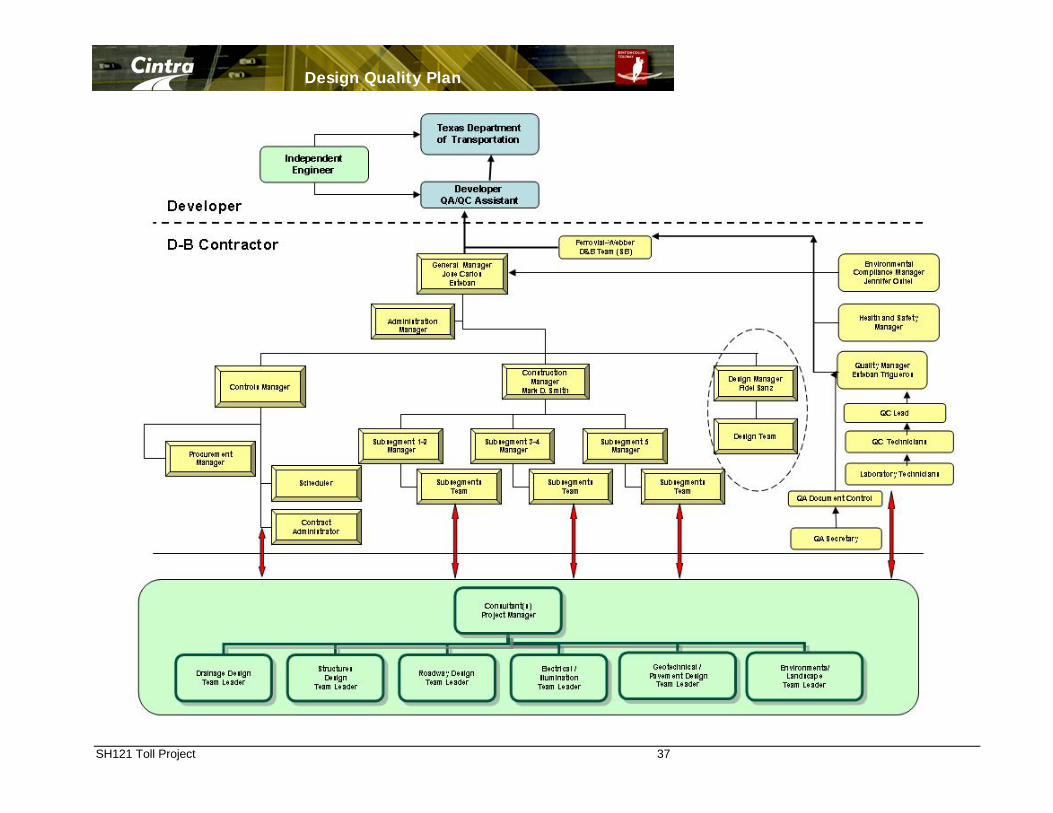
Design Quality Plan
SH121 Toll Project 37

Design Quality Plan
SH121 Toll Project 38
Attachment 2 D-B Team Process Procedures Manual

Design Quality Plan
SH121 Toll Project 39
D-B Team Process Procedures Manual
Table of Contents
Section Contents
1.1 Management Review
1.2 Contract Review
1.3 Documents and Data Control
1.4 Procurement (Materials)
1.5 Procurement (Subcontractor)
1.6 Traffic Management
1.7 Procurement (Design)
1.8 Construction Management
1.9 Control of Non-Conforming Products
1.10 Corrective and Preventative Action
1.11 Internal Audits
1.12 Complaints/Compliments
1.13 Health and Safety
1.14 Control of Quality and Environmental Records
1.15 Training
1.16 Utility Relocation
1.17 Quality Assurance Management
1.18 Geotechnical Investigation
1.19 Aesthetics and Landscaping

Design Quality Plan
SH121 Toll Project 40
Attachment 3 D-B Team Design Flow Procedure
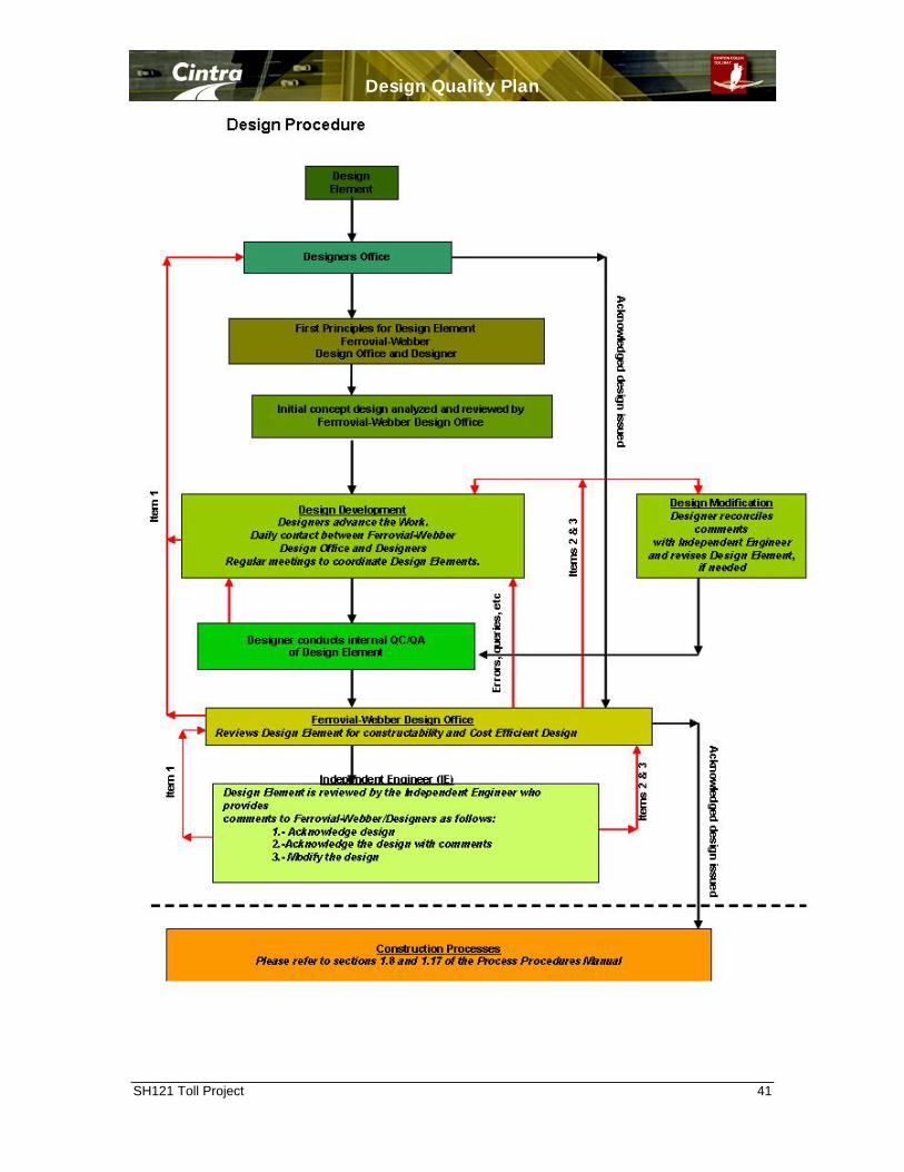
Design Quality Plan
SH121 Toll Project 41

Design Quality Plan
SH121 Toll Project 42
Attachment 4 D-B Team Design Schedule Refer to Appendixes D for further details

Design Quality Plan
SH121 Toll Project 43
Attachment 5 D-B Team Key and Specified personnel Requirements

Design Quality Plan
SH121 Toll Project 44
Job Description Job Title Responsible To Design Manager (Key personnel) General Manager Responsibilities: The Design Manager is responsible for managing the Design Team. The Design Manager shall also be responsible for ensuring that specific packages for design and related specifications meet the Comprehensive Development Agreement and Design and Build Agreement requirements. Further, that the design is functional and fulfils the specified criteria for safety, constructability, quality, cost effectiveness, and environmental guidelines with the project schedule. Duties shall also include the coordination of inter-disciplinary requirements within the various Consultants. On the completion of each design milestone, the Design Manager shall have the consultants certify that the design products have been completed in accordance with specified requirements. Prior to award of any procurement package related to design or professional services, the Design Manager is responsible for technical assessment of the proposers. During the duration of the project, the Design Manager shall also be responsible for providing engineering support to the project team to provide technical input during the procurement process and for reviewing change proposals. The Design Manager will review design packages from Consultants prior to issue for construction. A primary duty of the Design Manager is to establish an effective design review process to ensure that inter-disciplinary requirements have been completed prior to issue for procurement and, subsequently, for construction. The objective is to control changes without causing an adverse impact on the specified criteria, cost or schedule.

Design Quality Plan
SH121 Toll Project 45
CV: Key Expertise Fidel Sáenz de Ormijana
Project Experience:
2005-Present FERROVIAL AGROMAN US CORPORATION Based in Austin, Texas (USA) Technical Director for the High Priority IH 35 Trans
Texas Corridor Cintra Zachry LP
2001-2005 FERROVIAL AGROMÁN, S.A Based in Madrid (except 1999-2001, in Toronto) Leader of a 20 people team, responsible for design
of a wide number of projects Coordinating external consultants and internal
resources Author of over 16 papers. Design Manager for the
following works: 2001 - 2002 Preliminary Design for DBFO Tender A1 (Leeds, UK) –35 km. Preliminary Design for DBFO Tender N4-N6
(Ireland) –35 km. Preliminary Design for DBFO Tender Dundalk
(Ireland) –10 km of new construction. Preliminary Design for DBFO Tender SWM Detailed Design R-4 (Madrid, Spain) –90 km
1999 – 2001 Highway 407 ETR (Toronto, Ontario), extensions: West (26 km), East (15 km). Based in Toronto, Design Manager responsible for the coordination of 16+ consultants
and 12+ technical personnel in the B&B Contractor. Fast track project with very demanding deadlines where the design schedule was construction driven. Extensive public and stakeholder consultation. 1999 Detailed design for M-45 Concession Highway, Madrid (Spain). Preliminary design for tender Highway 407ETR (Toronto, Ontario). 1998 Preliminary design for tender SCUT Concession Highways Interior-Norte, Costa da Prata, Algarve (Awarded), Beira Interior e Alta, and Grande Porto. EUSKO JAULARITZA. Detail design for Marina in Hondarribia. Junta de Castilla y León. Obécuri Dam. Asistencia Técnica a la Construcción.
Education
Ph.D. in Civil Engineering University of Texas at Austin, Texas (EE.UU.) 1989
M.S. in Civil Engineering University of Texas at Austin TX (EE.UU.) 1986
B.S. in Civil Engineering Universidad Politecnica de Madrid, E.T.S.I. Caminos, Canales y Puertos, 1980
Reference See Attached Page

Design Quality Plan
SH121 Toll Project 46
Ayuntamiento de Valencia. Sur Ramal Exterior Sewer. Section Archiduque Carlos - Campos Crespo. Detail design of FGV railway subway. Secretaría de Recursos Naturales y Desarrollo Sustentable (Argentina). Preliminary design
for tender El Bolson Dam and Santa Josefa pipeline Secretaría de Recursos Naturales y Desarrollo Sustentable (Argentina). Preliminary design
for tender Canal Federal Tramo I and Río Hondo Pumping Station. Gobierno de la Provincia de Mendoza (Argentina). Preliminary design for tender Canal
Marginal Río Atuel. INRH (República Dominicana). Monción Dam. Filter design report.
1997 XUNTA DE GALICIA – Preliminary design for Caldas de Reis Dam. MIMAM – Preliminary design for long sea outfall Mompas (San Sebastián). MIMAM – Preliminary design for Ibiur Dam. MIMAM –Detail design for 40.000 Has irrigation subdivision Right Bank of Genil River.
Palma del Río (Córdoba). JUNTA DE CASTILLA Y LEÓN Detail design for Ronda Interior Sewer System (1500
meters). PUERTOS DEL ESTADO – Detail design for Ro-ro Berth in the San Carlos Wharf (Palma
de Mallorca). PUERTOS DEL ESTADO – Conceptual preliminary design for Solid Bulk Wharf Extension
(Alicante). SECRETARÍA DE RECURSOS NATURALES Y DESARROLLO SUSTENTABLE (ARGENTINA) –
Preliminary design for tender Acueducto Río Colorado. 1996 MIMAM – Preliminary design for Irueña Dam. MIMAM – Preliminary design for Sahechores Hydropower Plant (Civil Engineering). PUERTOS DEL ESTADO – Preliminary design for Guixar Wharf in Vigo. MIMAM – Preliminary design for tender Llucmajor. Wastewater Treatment Plant. JUNTA DE EXTREMADURA –Preliminary design for Jaraicejo Dam. MINISTERIO DE FOMENTO – Detail design for Costa del Sol Concession Highway (50
km). JUNTA DE EXTREMADURA – Detail design for Trujillo Dam. PUERTOS DEL ESTADO – Detail design for New Vehicle Terminal. Port of Tarragona.
1995 PUERTOS DEL ESTADO – Detail design for Poniente Berth Extension. Port of Palma de Mallorca. MOPTMA – Detail design for Lérida-Puigcerdá Road By-pass. MOPTMA – Preliminary design for tender Andévalo Dam (Huelva). MOPTMA - Preliminary design for tender La Loteta Dam (Zaragoza). MINISTERE DE L'AGRICULTURE - Project d'Amenagement L'oued Barbara (Tunez). MOPTMA – Detail design for Orotava-Los Realejos Highway (Tenerife). AUTEMA – Detail design for Tarrasa-Manresa Concession Highway repairs after 1995
flooding.

Design Quality Plan
SH121 Toll Project 47
1994 JUNTA DE EXTREMADURA – Preliminary design for tender Municipal Water Supply to Acebos, Hoyos, etc. (Cáceres) MOPT – Preliminary design for tender Peñarrubia Gijón-Este outfall. MINISTERE DE L'AGRICULTURE, Republique Tunisienne, D.G.G.T. - Project d'
Aménagement de L'Oued Barbara. Detail design for Conduit d'Amenee, Station de Pompage et Conduit de refoulement
Job Title Responsible To
Utility Manager Design Manager
Responsibilities:
The Utility Manager will coordinate and oversee Utility Adjustment operations during the planning, design, and construction phases of the Work. The Utility Manager will establish procedures and requirements for Adjusting Utilities including coordination with Utility Owners, engineering, and construction.
The Utility Manager will provide reports as specified in the Design and Build Agreement, Comprehensive Development Agreement, Technical Requirements, and other relevant contract documents.
Job Title Responsible To
Utility Design Coordinator Utility Manager
Responsibilities:
The Utility Design Coordinator will perform the following duties:
■ Coordinate the Utility Adjustment design with the overall highway design features during the planning, design, and construction phases of the Work.
■ Coordinate the design effort with TxDOT, utility Owners and Third Parties.
■ Prepare Utility Adjustment Assemblies and al related documents.
■ Procure and manage the SUE contractor, design consultants, and surveying companies.
■ Manage the preparation of Utility Strips Maps, Utility Adjustment Concept plans, SUE contractor, design consultants, and surveying companies.

Design Quality Plan
SH121 Toll Project 48
Job Description
Job Title Responsible To
Geotechnical Engineering Manager Design Manager
Responsibilities:
The Geotechnical Engineering Manager is responsible for the coordination of the Earthworks design and Geotechnical issues regarding Structure Foundations. The Geotechnical Engineering Manager shall be responsible for the control, inspections, checking and revision of the technical performance of the detail design and the financial cost of the services associated with the Design.
The Geotechnical Engineering Manager will check and oversee the Design prepared by the Geotechnical Subconsultant for incorporating into the works; will control Geotechnical Subconsultants, for compliance to Quality & Safety requirements; and shall coordinate the interface between different Designers which are involved in the scope of his duties.
The Geotechnical Engineering Manager will check the progress of the design to meet the design and the construction schedules. He is responsible for identifying and proposing to the Design Manager any necessary action to be taken in the event of a potential delay. He shall ensure, with the agreement of the Design Manager, that the requirements of the Design Schedule, relating Earthworks and Structures Foundation issues, are followed. He will record the actual progress.
The Geotechnical Engineering Manager will monitor Design performance and ensure that procedures are established and adhered to and, further, that all necessary documentation for verification is available in the project records. He will ensure that all relevant geotechnical information is provided to Document Control and is properly filed, updated and distributed. He will advise the Design Manager on any training requirements for staff.
The Geotechnical Engineering Manager will coordinate with the Quality Manager on matters related to Quality issues.
The Geotechnical Engineering Manager will investigate and recommend actions to the Design Manager for all items identified as requiring further development during the detail design which optimize the project.
The Geotechnical Engineering Manager shall attend to the design meetings arranged by the Design Manager to coordinate the different design elements and agree on a schedule of deliverables.

Design Quality Plan
SH121 Toll Project 49
Job Description
Job Title Responsible To
Structures Design Manager Design Manager
Responsibilities:
The Structures Design Manager shall ensure that the Design meets the Quality requirements with the agreement of the Design Manager, the Quality Manager, and the relevant Designers.
The Structures Design Manager shall review all design related issues to ensure they comply with contractual requirements and specifications.
The Structures Design Manager shall review the Consultants’ designs in order to meet the construction requirements and specifications and to assure clarity in drawings and related documents.
The Structures Design Manager ensures the design schedule complies with the Project Baseline Schedule.
The Structures Design Manager shall ensure that all the relevant persons and the Document Control System have the latest revisions of the Drawings.
The Structures Design Manager shall respond the queries raised by the Construction Manager and Segment Managers, and shall provide them with the information and documents they require.
The Structures Design Manager shall attend the design meetings arranged by the Design Manager to coordinate the different design elements and agree on a schedule of deliverables.

Design Quality Plan
SH121 Toll Project 50
Job Description
Job Title Responsible To
Highway Design Manager Design Manager
Responsibilities:
The Highway Design Manager is responsible for the coordination of the Highway design. The Highway Design Manager shall be responsible for the control, inspections, checking and revision of the technical performance of the detail design and the financial cost of the services associated with the Design. The Highway Design Manager’s duties include the following design elements: Site Clearance, Fencing and Environmental Barriers, Safety Fencing, Drainage, Road Pavement, Road Layout, Traffic Signs and Road Markings, Road Lighting and Electrical Works and Utilities design.
The Highway Design Manager will check and oversee the Design prepared by his staff and Subconsultant for incorporating into works. He will control the Highway Designer, for compliance with Quality & Safety requirements. He shall coordinate the interface between different Designers which are involved in the scope of his duties, with the agreement of the Design Manager.
The Highway Design Manager will check the progress of the design to meet the design and the construction schedules. He is responsible for identifying and proposing to the Design Manager any necessary actions to be taken in the event of a potential delay. He shall ensure, with the agreement of the Design Manager, that the requirements of the Design Schedule relating to Highway design issues are followed. He will record the actual progress.
The Highway Design Manager will monitor Design performance and ensure procedures are established and adhered to and that all necessary documentation for verification is available in the Project record. He will ensure that all relevant information provided to Document Control regarding Highway design is properly filed, updated and distributed. He will advise the Design Manager on any training requirements for staff.
The Highway Design Manager will investigate and recommend actions to the Design Manager on all items identified as requiring further development during the detail design which optimize the project.
The Highway Design Manager shall attend the design meetings arranged by the Design Manager to coordinate the different design elements and agree on a schedule of deliverables.

Design Quality Plan
SH121 Toll Project 51
Job Description
Job Title Responsible To
Chief Surveyor Design Manager/Construction Manager
Responsibilities:
The Chief Surveyor will be responsible to check and oversee Geometric control of the works.
He will also be responsible for quantity surveying to support supplier/subcontractor payment.
The Chief Surveyor will direct survey crews to meet the needs of the Construction Manager and Segment Managers.
The Chief Surveyor will assist with the preparation of As-Build drawings to the extent that survey data is required.