d45 system - legrand · d45 system front view lower view lift control interface description...
TRANSCRIPT

1
S2S1C FG
CF1
CF2
CF3
CF4
CF5
CF6
CF7
M
POWER
+-SYSTEM IN
OUTPUT1 OUTPUT2 OUTPUT3 OUTPUT4 OUTPUT5SYSTEM OUT
OUTPUT8 OUTPUT7 OUTPUT6
POWER L1 L2
ISPCF1
CF2
CF3
CF4
CF5
CF6
CF7
M
323017
S2S1C FG
CF1
CF2
CF3
CF4
CF5
CF6
CF7
M
POWER
+-SYSTEM IN
OUTPUT1 OUTPUT2 OUTPUT3 OUTPUT4 OUTPUT5SYSTEM OUT
OUTPUT8 OUTPUT7 OUTPUT6
POWER L1 L2
ISPCF1
CF2
CF3
CF4
CF5
CF6
CF7
M
323017
S2S1C FG
CF1
CF2
CF3
CF4
CF5
CF6
CF7
M
POWER
+-SYSTEM IN
OUTPUT1 OUTPUT2 OUTPUT3 OUTPUT4 OUTPUT5SYSTEM OUT
OUTPUT8 OUTPUT7 OUTPUT6
POWER L1 L2
ISPCF1
CF2
CF3
CF4
CF5
CF6
CF7
M
323017
141 mm
105 m
m
128,2 mm
94 m
m
33 mm
8 7 610
131415
9
1 2 3 4 5
1211
25/11/2013BT00792-a-
323017
D45 System
Front view
Lower view
Lift control interface
Description
LegendDimensional data
1. Configurators housing
2. Serial interface connector for PC configuration and firmware update
3. Relay OUTPUT 8 (connect to the corresponding key of lift)
4. Relay OUTPUT 7 (connect to the corresponding key of lift)
5. Relay OUTPUT 6 (connect to the corresponding key of lift)
6. Relay OUTPUT 5 (connect to the corresponding key of lift)
7. Relay OUTPUT 4 (connect to the corresponding key of lift)
8. Relay OUTPUT 3 (connect to the corresponding key of lift)
9. Relay OUTPUT 2 (connect to the corresponding key of lift)
10. Relay OUTPUT 1 (connect to the corresponding key of lift)
11. L1 - L2 Lift control status LEDs (see specific section)
12. S1 - S2 Manual device configuration pushbuttons (NOT USED)
13. RJ45 System OUT connection
14. RJ45 System IN connection
15. Auxiliary power supply input connector (30V)
Lift control device suitable to interface D45 VDE system with the building elevator system in order to control the lift call to the floor directly from the apartment internal unit. Device must be configured. NOTE : INSTALLATION AND CONNECTIONS MUST BE ALWAYS PERFORMED ACCORDINGLY TO THE ELEVATOR MANUFACTURER SPECIFICATION.
Technical data
Power supply: 30 VdcStand by current absorption: < 15 mA @ 30 VMax. operating current absorption: < 30 mA @ 30 VStand by power consumption: 0.45 WOperating power consumption: 0.9 WOperating temperature: (-10)-(+40)°C
EN

2
CF1 CF2 CF3 CF4 CF5 CF6 CF7 M
25/11/2013BT00792-a-
323017Lift control interface
Configuration
Lift control interface can be configured in 9 different modes(M = 1 to 9), depending on the following main requested features :
(M = 1) - suggested in case of floor with 1 entrance panel and total system entrance panel number less than 9.
(M = 2 to 9) - suggested in case of floor with more than 1 entrance panel or total system entrance panels higher than 8.
CONFIGURATION SETTINGS BY INSERTING PHISICAL CONFIGURATORS - WAY 1 :
Two different device configuration ways available:
WAY 1) Configuration settings by inserting phisical configurators
WAY 2) Configuration by using SF2 Software and PC connection
MODE (M = 1) meaning of the configurators :
WARNINGS :(*1) - CF5 + CF6 must be ≤ 8(*2) - Entrance panel calls internal unit and internal unit unlock,the output relay connected to the floor entrance panel act,after delay time,the output relay connected to the floor
internal unit act.
CF7 Delay time selection table
EN
Indication lights instruction for the corresponding lift control.
(L1) LED (L2) LED
EP call IU and IU unlock Flash Flash
EP unlock with card or password Flash No action
IU unlock in idle No action Flash
Stand by No action No action
CONFIGURATOR MODE 1 DESCRIPTION
CF1CF2
FF FF is corresponding to the 1st. PRIVATE floor (IU floor) managed by the device
CF3CF4
#II Apartment number for each floor
CF5 (*1) Quantity of PRIVATE floor (IU floor) managed by the device
CF6 (*1) Quantity of PUBLIC floor (EP floor) managed by the device
CF7 (*2) Delay time setting (see specific table below)
M Mode selection (1)
CF7 Configurator 0 1 2 3 4 5 6 7 8 9
Delay time (sec.) 1” 10” 20” 30” 40” 50” 60” 70” 80” 90”
3
25/11/2013BT00792-a-
323017Lift control interface
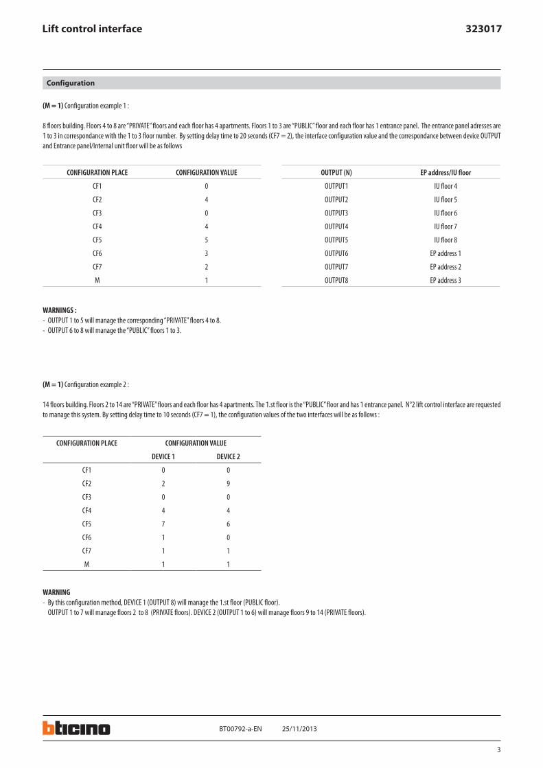
(M = 1) Configuration example 1 :
8 floors building. Floors 4 to 8 are “PRIVATE” floors and each floor has 4 apartments. Floors 1 to 3 are “PUBLIC” floor and each floor has 1 entrance panel. The entrance panel adresses are 1 to 3 in correspondance with the 1 to 3 floor number. By setting delay time to 20 seconds (CF7 = 2), the interface configuration value and the correspondance between device OUTPUT and Entrance panel/Internal unit floor will be as follows
(M = 1) Configuration example 2 :
14 floors building. Floors 2 to 14 are “PRIVATE” floors and each floor has 4 apartments. The 1.st floor is the “PUBLIC” floor and has 1 entrance panel. N°2 lift control interface are requested to manage this system. By setting delay time to 10 seconds (CF7 = 1), the configuration values of the two interfaces will be as follows :
Configuration
WARNINGS :- OUTPUT 1 to 5 will manage the corresponding “PRIVATE” floors 4 to 8.- OUTPUT 6 to 8 will manage the “PUBLIC” floors 1 to 3.
WARNING- By this configuration method, DEVICE 1 (OUTPUT 8) will manage the 1.st floor (PUBLIC floor).
OUTPUT 1 to 7 will manage floors 2 to 8 (PRIVATE floors). DEVICE 2 (OUTPUT 1 to 6) will manage floors 9 to 14 (PRIVATE floors).
EN
CONFIGURATION PLACE CONFIGURATION VALUE OUTPUT (N) EP address/IU floor
CF1 0 OUTPUT1 IU floor 4
CF2 4 OUTPUT2 IU floor 5
CF3 0 OUTPUT3 IU floor 6
CF4 4 OUTPUT4 IU floor 7
CF5 5 OUTPUT5 IU floor 8
CF6 3 OUTPUT6 EP address 1
CF7 2 OUTPUT7 EP address 2
M 1 OUTPUT8 EP address 3
CONFIGURATION PLACE CONFIGURATION VALUE
DEVICE 1 DEVICE 2
CF1 0 0
CF2 2 9
CF3 0 0
CF4 4 4
CF5 7 6
CF6 1 0
CF7 1 1
M 1 1

4
25/11/2013BT00792-a-
323017Lift control interface
(M = 2 to 9) meaning of the configurators :
(M = 2 to 9) Configuration example 3 :
System with : 2 entrance panels in the underground floor, 3 entrance panels in the 1.st floor. Floors 2 to 9 are “PRIVATE” floors and each floor has 4 apartments. By setting delay time to 20 seconds (CF7 = 2), the configuration values of the two interfaces will be as follows :
Configuration
WARNING- The relationship between CF(N) and CF(N+1) should meet the rule : CF(N+1) = CF(N) or CF(N+1) = CF(N) + 1- The configuration value indicate the output channel of the entrance panel address- Using configuration MODE (M=2 to 9),each channel correspond to one entrance panel address. The entrance panel address can be calculated by the following rule : A=(M-2) x 7 + N.
A means Entrance Panel address, M means MODE, N means configuration place such as CF1 means N=1. The phisical configuration value means the channel number.
WARNINGBy this configuration method, DEVICE 1 (OUTPUT 1) will manage the 2 entrance panels (EP with address 1 and 2) of the underground floor; DEVICE 1 (OUTPUT 2) will manage the 3 entrance panels (EP with address 3 to 5) of the 1.st floor; DEVICE 2 (OUTPUTS 1 to 8) will manage the “PRIVATE” floors 2 to 9.
EN
CONFIGURATION PLACE CONFIGURATION VALUE
CF1 (N=1) The corresponding OUTPUT channel
CF2 (N=2) The corresponding OUTPUT channel
CF3 (N=3) The corresponding OUTPUT channel
CF4 (N=4) The corresponding OUTPUT channel
CF5 (N=5) The corresponding OUTPUT channel
CF6 (N=6) The corresponding OUTPUT channel
CF7 (N=7) The corresponding OUTPUT channel
M M=2–9
CF1 CF2 CF3 CF4 CF5 CF6 CF7
M=2 1 2 3 4 5 6 7
M=3 8 9 10 11 12 13 14
M=4 15 16 17 18 19 20 21
M=5 22 23 24 25 26 27 28
M=6 29 30 31 32 33 34 35
M=7 36 37 38 39 40 41 42
M=8 43 44 45 46 47 48 49
M=9 50 51 52 53 54 55 56
CONFIGURATION PLACE CONFIGURATION VALUE
DEVICE 1 DEVICE 2
CF1 1 0
CF2 1 2
CF3 2 0
CF4 2 4
CF5 2 8
CF6 0 0
CF7 0 2
M 2 1

5
S2S1C FG
CF1
CF2
CF3
CF4
CF5
CF6
CF7
M
POWER
+-SYSTEM IN
OUTPUT1 OUTPUT2 OUTPUT3 OUTPUT4 OUTPUT5SYSTEM OUT
OUTPUT8 OUTPUT7 OUTPUT6
POWER L1 L2
ISPCF1
CF2
CF3
CF4
CF5
CF6
CF7
M
323017
25/11/2013BT00792-a-
323017Lift control interface
CONFIGURATION BY USING SF2 SOFTWARE AND PC CONNECTION - WAY2:
This is the (SUGGESTED) enhanced way to download the device configuration to the lift control interface device previously created by using SF2 configuration software and a personal computer. To transfer use the configurator hardware tool 323020 serial interface.
WARNINGIn order for the communication to take place, device must be powered and not phisically configured.
Configuration
323020
configuration tool
EN

6
ON
SD
1
2
3
4
ON
SD
1
2
3
4
323003
1 2
323002
IU1
IU2
IU3
IU4
1 2
323002
IU1
IU2
IU3
IU4
1 2
323002
IU1
IU2
IU3
IU4
1 2
323002
IU1
IU2
IU3
IU4
1 2
323002
IU1
IU2
IU3
IU4
1 2
323002
IU1
IU2
IU3
IU4
S2S1C F G
CF1
CF2
CF3
CF4
CF5
CF6
CF7
M
POWER
+-SYSTEM IN
OUTPUT1 OUTPUT2 OUTPUT3 OUTPUT4 OUTPUT5SYSTEM OUT
OUTPUT8 OUTPUT7 OUTPUT6
POWER L1 L2
ISPCF1
CF2
CF3
CF4
CF5
CF6
CF7
M
323017
323017
S2S1C F G
CF1
CF2
CF3
CF4
CF5
CF6
CF7
M
POWER
+-SYSTEM IN
OUTPUT1 OUTPUT2 OUTPUT3 OUTPUT4 OUTPUT5SYSTEM OUT
OUTPUT8 OUTPUT7 OUTPUT6
POWER L1 L2
ISPCF1
CF2
CF3
CF4
CF5
CF6
CF7
M
323017
323017
OUTPUT1
OUTPUT2
OUTPUT3
OUTPUT4
OUTPUT5
OUTPUT6
OUTPUT7
OUTPUT8
OUTPUT1
OUTPUT2
OUTPUT3
OUTPUT4
OUTPUT5
OUTPUT6
OUTPUT7
OUTPUT8
OR
EP1
CF1
CF2
CF3
CF4
CF5
CF6
CF7
0 2 0 4 7 1 1 1
M
CF1
CF2
CF3
CF4
CF5
CF6
CF7
0 9 0 4 6 0 1 1
M
IN IN OUT
IN OUT
OUT
IN
IN
OUT
EPSUB SYSTEM
Wiring diagram
25/11/2013BT00792-a-
323017Lift control interface
Down key of lift in 14 floor
Down key of lift in 9 floor
Down key of lift in 7 floor
Down key of lift in 2 floor
Down key of lift in 8 floor
UP key of lift in 1 floor
Down key of lift in 3 floor
Down key of lift in 13 floor
Down key of lift in 10 floor
Wiring diagram example 1:
Building with 14 floors : floors 2 to 14 are PRIVATE floors and every floor has 4 apartments. Floor 1 is a PUBLIC floor with one entrance panel. Delay time set as 10 sec. (CF7 = 1). This system needs N° 2 lift control interfaces.
EN
7
ON
SD
1
2
3
4
ON
SD
1
2
3
4
323003
1 2
323002
IU1
IU2
IU3
IU4
1 2
323002
IU1
IU2
IU3
IU4
1 2
323002
IU1
IU2
IU3
IU4
1 2
323002
IU1
IU2
IU3
IU4
1 2
323002
IU1
IU2
IU3
IU4
S2S1C F G
CF1
CF2
CF3
CF4
CF5
CF6
CF7
M
POWER
+-SYST EM IN
OUTPUT1 OUTPUT2 OUTPUT3 OUTPUT4 OUTPUT5SYSTEM OUT
OUTPUT8 OUTPUT7 OUTPUT6
POWER L1 L2
ISPCF1
CF2
CF3
CF4
CF5
CF6
CF7
M
323017
323017
S2S1C F G
CF1
CF2
CF3
CF4
CF5
CF6
CF7
M
POWER
+-SYST EM IN
OUTPUT1 OUTPUT2 OUTPUT3 OUTPUT4 OUTPUT5SYSTEM OUT
OUTPUT8 OUTPUT7 OUTPUT6
POWER L1 L2
ISPCF1
CF2
CF3
CF4
CF5
CF6
CF7
M
323017
323017
OUTPUT1
OUTPUT2
OUTPUT3
OUTPUT4
OUTPUT5
OUTPUT6
OUTPUT7
OUTPUT8
OUTPUT1
OUTPUT2
OUTPUT3
OUTPUT4
OUTPUT5
OUTPUT6
OUTPUT7
OUTPUT8
OR OR OR
EP3 EP5
OR OR
EP4
EP1 EP2
1 2 3 4
323004
CF1
CF2
CF3
CF4
CF5
CF6
CF7
0 2 0 4 8 0 2 1
M
CF1
CF2
CF3
CF4
CF5
CF6
CF7
1 1 2 2 2 0 0 2
M
IN IN OUT
ININ OUT
OUT
IN OUT
EP EP OUTSUB SYSTEM
EP 5
EP 4
EP 3
EP 2
EP 1
-1 FLOOR
1 FLOOR
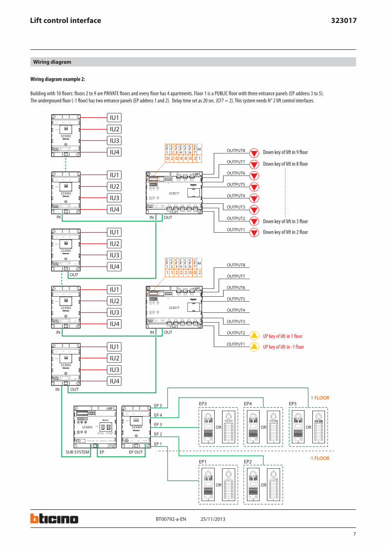
Wiring diagram
25/11/2013BT00792-a-
323017Lift control interface
Down key of lift in 9 floor
Down key of lift in 8 floor
Down key of lift in 3 floor
Down key of lift in 2 floor
UP key of lift in 1 floor
UP key of lift in -1 floor
Wiring diagram example 2:
Building with 10 floors: floors 2 to 9 are PRIVATE floors and every floor has 4 apartments. Floor 1 is a PUBLIC floor with three entrance panels (EP address 3 to 5). The underground floor (-1 floor) has two entrance panels (EP address 1 and 2). Delay time set as 20 sec. (CF7 = 2). This system needs N° 2 lift control interfaces.
EN