d4.1/d4.2 automation strategies for solid rock and soft ... · pdf file2.2.2...
TRANSCRIPT

DRAGON D4.1/D4.2 End User Requirements & Specifications
© DRAGON consortium: all rights reserved page 0
D4.1/D4.2 Automation Strategies for solid rock
and soft ground processing
DRAGON Identifier:
DRAGON-D41-D42-B+G-001-02-AutomationStrategies
Author(s) and company:
Document status:
Manuel Petitat, Katja von Allmen, Tiziana Minotti, Cedric Thalmann (all of B+G), Christian Himmelsbach, Thomas Edelmann, Manuel Gehrig (all of HK), Jacques Burdin (JB)
Final
Confidentiality: Publishable
Keywords: Tunnel Boring Machines, EPB-Machines, Mixshield Machines, Material Processing Strategies, Cutting Parameters
Abstract: This report includes the material processing strategies and prototype
concepts.
Version Date Reason of change 1 21/03/2014 Document created2 31/03/2014 Document finalized after Internal Review by PORR

DRAGON D4.1/D4.2 Automation Strategies for solid rock and soft ground processing
© DRAGON consortium: all rights reserved
Table of Content
1 Executive Summary........................................................................................................... 1
2 General Approach / Introduction ...................................................................................... 2
2.1 Hard rock tunnel boring machines (TBMs) ................................................................... 2 2.1.1 Gripper TBM ...............................................................................................................................................................2 2.1.2 Single Shield TBM ......................................................................................................................................................4 2.1.3 Double shield TBM .....................................................................................................................................................6
2.2 Softground tunnel boring machines .............................................................................. 8 2.2.1 Slurry shield / Mixshield .............................................................................................................................................8 2.2.2 Earth-pressure-balance shield (EPB) .......................................................................................................................11
3 Technological strategy for automated solid rock processing .................................... 14
3.1 Definition of relevant raw material requirements and quality criteria for its on-site use as aggregates for various products, e.g. shotcrete and grout ............................................. 14
3.1.1 Introduction ..............................................................................................................................................................14 3.1.2 The different rock quality assessment steps ............................................................................................................14 3.1.3 Test and quality control concept ..............................................................................................................................15
3.2 Research emphasis on a material processing plant for fast and online separation between useful and non-useful resources .......................................................................... 18
3.2.1 Introduction ..............................................................................................................................................................18 3.2.2 Description of TBM muck .........................................................................................................................................18 3.2.3 TBM muck processing alternatives: Wet vs dry .......................................................................................................19 3.2.4 Experience from previous construction sites............................................................................................................21 3.2.5 Dry Processing vs wet processing on a TBM back-up .............................................................................................23 3.2.6 Determination of possible aggregate production on TBM ........................................................................................24 3.2.7 Production of shotcrete aggregate on a TBM ..........................................................................................................25 3.2.8 Production of in-situ concrete aggregate on a TBM .................................................................................................26 3.2.9 Production of invert filling aggregate on a TBM .......................................................................................................28 3.2.10 Production of mortar aggregates for back filling on a TBM ......................................................................................29 3.2.11 Overall production of aggregate and concrete on TBM back-up .............................................................................29
3.3 Optimization of the cutting parameters regarding the requirements for the excavation material ............................................................................................................................... 30
3.4 Basics for the prototype design regarding the in-situ production of aggregates ......... 31 3.4.1 Usage potential of excavated material in tunneling .................................................................................................31 3.4.2 Proportion of TBM muck used during tunnelling ......................................................................................................32 3.4.3 Definition and dimensioning of the processing components ....................................................................................33 3.4.4 Design concept of the processing plants inside the tunnel ......................................................................................34
3.5 Example ...................................................................................................................... 36 3.5.1 Example Brenner Base Tunnel – LOT Tulfes Pfons ................................................................................................36 3.5.2 Example Geology - Exploratory tunnel Ahrental ......................................................................................................37 3.5.3 Excavation parameters of the exploratory tunnel Ahrental ......................................................................................38 3.5.4 Description of possible recycling processes for the TBM-systems ..........................................................................39 3.5.5 Space requirements of TBM material recycling plant for shotcrete production during BBT .....................................39 3.5.6 Animation .................................................................................................................................................................40
4 Technological strategy for automated soft ground processing ................................. 41
4.1 Approaches for Mixshield machines ........................................................................... 42 4.1.1 Slurry treatment – Description of the separation plant .............................................................................................42 4.1.2 Electro-coagulation ..................................................................................................................................................44
4.2 Examples .................................................................................................................... 48 4.2.1 Karlsruhe Kombilösung ............................................................................................................................................48

DRAGON D4.1/D4.2 Automation Strategies for solid rock and soft ground processing
© DRAGON consortium: all rights reserved
4.2.2 Use of excavated material from Karlsruhe Kombilösung .........................................................................................48 4.2.3 Processing method for excavated material from Karlsruhe Kombilösung ...............................................................48
4.3 Approaches for EPB machines ................................................................................... 50 4.3.1 General introduction: ................................................................................................................................................50 4.3.2 Optimization of the soil conditioning system ............................................................................................................50 4.3.3 Recovery of soil conditioning agents........................................................................................................................57 4.3.4 Quality control of conditioned soil ............................................................................................................................62
5 Exploitable Knowledge and its Use ............................................................................... 64
6 Conclusion ....................................................................................................................... 65
7 References ....................................................................................................................... 68
8 Annex ................................................................................................................................ 69

DRAGON D4.1/D4.2 End User Requirements & Specifications
© DRAGON consortium: all rights reserved page 1
1 Executive Summary
Within the last 20 years, spoil management has gained importance on large construction site. Tunnel boring machine (TBM) excavated material (muck), if suitable, can be processed in high-quality aggregates for on-site or external uses. Depending on the type of TBM chosen for a specific project (hardrock vs softground), strategies for the development of automate aggregate processing differ (e.g., different excavation processes and different target materials and final uses).
Within this paper the automated material processing on hard-rock (WP4.1) and soft-
ground (WP4.2) TBMs are discussed.
In the second chapter, we describe the various types of TBMs (hardrock vs softground). The third chapter is devoted to the automated material processing on hard rock TBMs and is composed of the following main subjects:
Definition of the relevant and minimal raw material processing requirements as well
as the quality criteria for on-site use of hard-rock TBM muck as aggregate for various
products (e.g. shotcrete)
Study of the effect of spacing on the size and depth of TBM chips (upgrade of muck
spoil processing and correlation between raw material quality and spacing)
Description of the different methods of hard-rock material processing for fast and
online separation between useful and non-useful resources.
Presentation of the aggregates, which can be produced on a hard-rock TBM back-up
and the way they will be processed.
Presentation of a basic prototype design to process high-quality aggregates on a
hard-rock TBM back-up based on the previous considerations
Illustration of our view with the Brenner Base Tunnel (BBT) example.
The fourth chapter concentrates on automated processing strategies for softground Tunnel boring machines. It includes two main chapters discussing new automation systems for mixshield and EPB (Earth Pressure Balance) TBMs, respectively. Main topics of each part are:
Process description and quality criteria for automated processing of softground
material compounds (e.g., Bentonite and gravel)
New ways for slurry classification and separation
Automation of slurry gravel, bentonite and slurry segregation using already existing
and innovative new technologies for an automated softground processing prototype.
So, what are the different types of TBMs? And what are their respective characteristics?

DRAGON D4.1/D4.2 Automation Strategies for solid rock and soft ground processing
© DRAGON consortium: all rights reserved page 2
2 General Approach / Introduction
The existing technology of mechanized tunneling systems with diameters larger than 4m can be generally classified into hard rock TBMs and soft ground TBMs. As basis for the planned processing strategies described later in this deliverable, we present in this chapter the basics of the main TBM machines used for driving in both types of rock (solid and soft).
2.1 Hard rock tunnel boring machines (TBMs)
The modern hard rock tunneling tunnel boring machines (TBMs) compete with conventional drilling and blasting methods. In the hard rock world, the excavated face is predominantly stable, non-groundwater-bearing and with solid rock of different hardness and other properties and thus different potential for being used as raw material inside or outside the tunnel. TBMs allow for an almost continuous drilling through all kind of rocks combined with a semi-automated tunnel construction behind the machine. Different hard rock projects need different machine types which are open (Gripper) or shielded (single or double shield) TBMs. The differences are explained in the sections below, automation strategies for solid rock processing based upon these technological varieties are described in chapter 3.
2.1.1 Gripper TBM
Gripper TBMs have proven to be efficient solutions for fast mechanized tunneling in hard rock on many occasions. Due to the process-typical rock support method without segments, medium to high rock strengths are a requirement for high advance rates. In more fractured geological formations, various systems for immediate rock support behind the cutterhead are installed at the TBM directly.
Figure 2-1: Illustration of a typical Herrenknecht Gripper TBM with a diameter of 8.5 m.
Source: Herrenknecht AG

DRAGON D4.1/D4.2 Automation Strategies for solid rock and soft ground processing
© DRAGON consortium: all rights reserved page 3
Mode of operation:
When tunneling with a Gripper TBM (Figure 2-1), a rotating cutterhead equipped with disc cutters is pressed against the tunnel face with a pressure of up to 32 tons per disc. Due to the rolling movement of the cutter, single pieces – so-called chips – are broken out of the rock. Water jets can cool the cutting tools and reduce dust formation. Buckets installed at the cutterhead take up the excavated material, which slides to the center of the machine via integrated muck chutes while the cutterhead rotates, and then falls through the funnel-shaped muck ring onto the machine belt. From there, the rock chips are passed on via further belt conveyors or transport vehicles and removed from the tunnel. Before each stroke, the Gripper TBM is braced against the previously excavated tunnel using laterally extendible hydraulic cylinders (Figure 2-2).
Figure 2-2: Grippers on TBM. Source: AlpTransit.
The laterally mounted gripper plates or gripper shoes are the core element of this machine type, hence the name of the machine. Subsequently, the thrust cylinders are braced against the gripper unit and push the rotating cutterhead against the tunnel face. Several telescopic partial shields stabilize the machine against vibrations during the boring process, thus reducing wear and tear. The invert shield also serves as a guide shoe for the TBM. Lateral partial shields are pressed against the rock with a stabilizing effect. The roof shield above this unit, often equipped with a finger shield extending backwards, offers protection against breaking rock. After completion of a stroke, tunneling is interrupted and the gripping unit is moved forward.
The gripper unit also helps controlling the TBM. The main beam is positioned in the center of the machine. The beam is moved vertically and horizontally using the hydraulic cylinders in the area of the gripper unit. This allows for precise control. The current position of the TBM is permanently monitored and adjusted to the specified alignment if necessary.
Gripper TBMs are open-mode tunnel boring machines and do not have a closed shield skin. Therefore, the tunneling performance depends on the time required to secure the rock. Normally, rock anchors, steel mats and steel arches are used for securing. Probing and, if necessary, soil conditioning ahead of the machine are possible using additional drilling rigs. Water influx from the rock is pumped away via a drainage system in the invert section of the machine.

DRAGON D4.1/D4.2 Automation Strategies for solid rock and soft ground processing
© DRAGON consortium: all rights reserved page 4
The excavated tunnel diameter is permanently supported with shotcrete in the back-up area. All necessary supply facilities are installed there. This often includes, in addition to the installation of permanent shotcrete, the installation of invert segments.
Gripper TBMs offer a special advantage in comparison to closed shield types (which will be described in sections 2.1.1 and 2.1.2): All shields can be retracted to reduce the overall diameter during tunnelling which allows for a flexible reaction to expanding rock and prevents the machine from jamming. With the aid of the gripper unit, the machine can even be retracted completely, if necessary. This means that the front part of the cutterhead can be accessed directly.
Gripper TBMs achieve very high advance rates in stable rock formations at low operating costs. Thus, they can excavate even very long tunnel sections like the Gotthard Base Tunnel quickly and successfully.
2.1.2 Single Shield TBM
Single Shield TBMs (Figure 2-3) are ideal machines for tunneling through rock and other stable, non-groundwater-bearing soils. Due to the typical tunneling methods with segmental lining or pipe jacking, high tunneling performances can also be achieved in rock formations with low stand-up times and in fractured rock.
Figure 2-3: Illustration of a typical segmental lining single shield machine (diameter 9 m).
Source: Herrenknecht AG
Mode of operation:
Single Shields belong to the family of shield machines like Slurry Shields (section 2.2.1) or EPB Shields (section 2.2.2). However, there is an essential difference between them: Single Shield TBMs have no closed excavation chamber. Thus this type of machine cannot be used in strongly water-bearing or very soft soils due to the missing feature of pressure balance. The advantage of the shield is its protection ability.

DRAGON D4.1/D4.2 Automation Strategies for solid rock and soft ground processing
© DRAGON consortium: all rights reserved page 5
The machine is protected at all times by the shield, additional measures to secure the rock are usually not necessary and corresponding delays in tunneling can be avoided. The shield extends from the cutter head over the entire machine. The tunnel lining, performed with reinforced concrete segments, is installed under the protection of the shield tail.
Buckets installed at the cutterhead take up the excavated material which slides to the machine’s center through integrated muck chutes. During cutterhead rotation material continues falling through the funnel-shaped muck ring onto the machine belt (Figure 2-4).
Figure 2-4: Buckets, chutes and muck ring provide for efficient removal of the excavated material.
Source: Herrenknecht AG
Shielded Hard Rock TBMs have an excavation diameter which is larger than the shield skin. In addition, the excavation axis of the cutterhead is slightly higher than the machine axis. This overcut makes it possible to control the machine and protects it against jamming in the rock. Hydraulic stabilizer plates integrated into the shield can be braced in the already excavated tunnel. This reduces vibrations and stabilizes the machine during the boring process.
To control the machine, either firmly installed drives with steering cylinders or movable drives with articulation bearings or torque box cylinders and additional longitudinal displacement cylinders are used. This allows for tunnelling with very small radii. With all drive types, the cutterhead can be pulled back allowing direct access to the tunnel face. This means that the disc cutters worn out in the excavation process can be easily replaced. Another special feature applies to the Single Shield TBM in pipe jacking: the cutterhead can be rotated in both directions which counters the risk of the machine rolling.
The Single Shield TBM is secured in the ground using segments or pipe jacking. This minimizes the dependency between tunnelling and tunnel lining in brittle rock formations or rock with low strength. In accessible machines, soil conditioning enhances the geological range of application. Water inflows can thus be reduced to a controllable measure. For this purpose, an injection body is built up in front of the tunnel face using injection drills through the cutterhead and the shield. Drainage systems drain the entering water in a controlled manner.
Tunneling through hard rock with strengths of up to 250 megapascal at some places requires enormous forces. The disc cutters can only break the hard rock if a very high contact pressure is applied. If chips are big, this is proof of fast tunnelling with optimum pressure force and low wear and tear of the disc cutters. If the contact pressure is too low, the rock is not crushed ideally and the discs wear out faster.

DRAGON D4.1/D4.2 Automation Strategies for solid rock and soft ground processing
© DRAGON consortium: all rights reserved page 6
With smaller excavation diameters and restricted space for the cutting tools, in particular, the cutterhead design, torque and contact pressure must be coordinated exactly, taking the expected geology into account. The optimum arrangement of the disc cutters on the cutterhead and drives with a strong torque and high contact pressure are the most important factors in ensuring fast tunnelling through hard rock with as little wear and tear as possible.
Another difference to Slurry and EPB shields is the backfilling material used for the annular gap between outer segment face and tunnel wall. Here, usually pea-gravel is being applied whereas on soft ground machines usually a grout injection takes place.
Single Shield TBMs are all-rounders for tunneling in rock formations due to the simple tunneling concept in combination with a wide range of applications. In many cases, they are the optimum solution for tunneling with very high rock strengths both in pipe jacking and segmental lining. In addition, single shields can be used successfully in groundwater-bearing rock formations using soil conditioning.
2.1.3 Double shield TBM
Double Shield TBMs (Figure 2-5) are technically counted among the most sophisticated tunnel boring machines. They unify the functional principles of Gripper and Single Shield TBMs in one machine. Under stable geological conditions, the combination of methods allows for the installation of concrete segments parallel to tunneling, achieving very high tunneling performances. This technology is therefore perfectly suited for excavating long tunnels in hard rock with short stand-up time and in fractured rock.
Figure 2-5: Illustration of a typical segmental lining double shield machine (diameter 5.4 m).
Source: Herrenknecht AG

DRAGON D4.1/D4.2 Automation Strategies for solid rock and soft ground processing
© DRAGON consortium: all rights reserved page 7
Mode of operation:
The machine consists of two main components, the front shield including cutterhead, main bearing and drive and the gripper shield (or main shield) consisting of the gripping unit, the auxiliary thrust cylinders and the tailskin. The shields are connected with telescopic jacks, the main thrust cylinders, which are protected by the telescopic shield where the shield skins of the front and gripper shield overlap. The machine can either adequately clamp itself radially in the tunnel under stable rock conditions by using the clamping units of the gripper shield; or where the geology is weak, it can push off the existing lining in the direction of the drive. The front shield can thus be advanced independently of the gripper shield, so that in general continuous operation is possible, nearly independent of segment installation. However, the telescopic joint might be blocked when used in fractured rock with high strength.
When tunneling with a Double Shield TBM, a rotating cutterhead equipped with disc cutters is pressed against the tunnel face with a pressure of up to 32 tons per disc. Due to the rolling movement of the discs, single pieces – so-called chips – are broken out of the rock. Water jets can cool the cutting tools and reduce dust formation. Buckets installed at the cutterhead take up the excavated material before it slides to the center of the machine through integrated muck chutes while the cutterhead rotates and then falls through the funnel-shaped muck ring onto the machine belt. At the end of the machine belt, the rock chips are passed on to belt conveyors or transport vehicles and removed from the tunnel.
The reaction forces during the excavation process are transferred into the rock by the extended gripper shoes. Simultaneously to tunneling, the segments are installed in the tailskin section. The auxiliary thrust cylinders serve only to secure the position of the concrete segments placed. When the stroke is completed, the gripper shoes are loosened and the gripper shield is pushed behind the front shield using the auxiliary thrust cylinders. Regripping lasts only a few minutes, which means that tunneling is almost continuous. In ideal rock formations, Double Shield TBMs can also operate without segmental lining.
In fault zones or areas of low rock strength, radial bracing of the gripper shoes is not possible. In these sections, the machine can be driven in Single Shield mode: the telescopic shield can be retracted completely so that the front and gripper shields form a rigid unit. The necessary thrust forces are applied using the auxiliary thrust cylinders. As with the Single Shield TBM, the last segment ring installed serves as a counter bearing to advance the machine. Thrust and ring building can no longer take place simultaneously. In turn, this discontinuous mode provides for higher tunnelling safety in difficult sections of the alignment.
Double Shield TBMs have a comparatively long shield skin. In cases of rock convergence there is an increased risk of the machine becoming jammed. A range of design solutions exist to deal with this problem. These include graded shield diameters and a vertical shift of the longitudinal axes of cutterhead, front and gripper shield, for example. Crumbling rock and excavated material can block the telescopic joint and the annular gap. This makes it difficult to push the gripper shield ahead. As a countermeasure, Double Shield TBMs usually have a telescopic shield which can be moved independently. Using additional displacement cylinders, access to the tunnel wall can be provided if this is necessary for cleaning or securing measures. Additional drilling devices and drilling ports in the shield section serve to secure the open telescopic section above the TBM using a pipe arch.
In the diameter range from 2.8 to 6 meters, Double Shield TBMs are equipped with permanently installed drives with straight-positioned main thrust cylinders or v-positioned lattice cylinders. Tunneling control is carried out directly by the cylinders. For diameters of more than 6 meters, movable drives with additional longitudinal displacement cylinders are generally used. Through the cylinders, the contact pressure of the drive can be measured directly, making optimum use of the power provided.

DRAGON D4.1/D4.2 Automation Strategies for solid rock and soft ground processing
© DRAGON consortium: all rights reserved page 8
An articulation bearing or torque box cylinders help control the TBM. The latter provide for continuous horizontal and vertical shift of the drive. In this way, the cutterhead can be steered precisely in all directions and can even produce a local overcut. The cutterhead can be pulled back with all drive types, allowing direct access to the tunnel face.
Double Shield TBMs are mainly used for tunnel projects in changing rock formations. They achieve very high tunneling performances in stable rock by working in continuous tunneling mode. Therefore, the combined method of Gripper and Single Shield TBM is often the quickest and most cost effective solution for long drives in hard rock.
2.2 Softground tunnel boring machines
Softground TBMs are shielded machines similar to Single and Double Shield TBMs. Additionally, they have a closed excavation chamber to be able to operate under even high-pressure groundwater conditions. The soil water pressure must be compensated by a supporting medium which is essentially different between Mixshields and EPBs as explained in the following sections. This also influences the strategies of raw material extraction on softground TBMs which will be described in chapter 4 starting on page 41.
2.2.1 Slurry shield / Mixshield
The bentonite suspension used as support medium to stabilize the tunnel face gave the Slurry Shield its name. The Mixshield technology developed by Herrenknecht is an advance on conventional slurry technology. The support pressure in the excavation chamber is precisely managed using an automatically controlled air cushion. This means that heterogeneous geologies and high water pressures of more than 15 bar can be controlled safely even with very large excavation diameters.
Figure 2-6: Illustration of a typical segmental lining MIX-shield-machine (10 m).
Source: Herrenknecht AG 1 Cutting wheel and excavation chamber, 2 Submerged wall, 3 Working chamber, 4 Bulkhead, 5 Slurry circuit, 6 Thrust cylinder, 7 Segment erector, 8 Tailskin, 9 Tunnel lining

DRAGON D4.1/D4.2 Automation Strategies for solid rock and soft ground processing
© DRAGON consortium: all rights reserved page 9
Mode of operation:
A characteristic feature of Mixshields (Figure 2-6) is an excavation chamber that is divided by a so-called submerged wall. The front section of the excavation chamber is completely filled with bentonite suspension for full tunnel face support during tunneling. In the rear section between submerged wall and bulkhead (working chamber) the suspension reaches up to only just above the machine axis. The counter-pressure needed at the tunnel face is supplied using a compressible air cushion in the upper section. Communication between the two chambers takes place through a submerged wall opening in the invert section.
Fully-automated control circuits permanently monitor pressure conditions and ensure considerably more precise pressure control than in conventional one-chamber systems. Decoupling the circulating suspension from support pressure control provides for higher flexibility and safety during tunnelling. Since it is possible to react directly through the air cushion, even small pressure and volume fluctuations in heterogeneous geologies can be controlled exactly. This allows for much better control in terms of heave and settlement, which must be avoided, especially with little overburden.
Mix shields can be used safely even with high water pressures of more than 15 bar due to their closed hydraulic slurry circuit. However, this requires a sealing layer between the machine and the ground to be excavated. This is why Mixshields are equipped with a multiple sealing system. The main drive seal is designed as a system with individual sealing chambers containing pressurized sealant. At the rear of the machine, the annular gap between the inside of the tailskin and the outside of the segmental lining is sealed with multiple wire brushes to keep out the soil and groundwater.
In typical Mixshield tunnelling operations in incohesive, heterogeneous soils, larger stones or boulders must be expected. Such blocks need to be crushed to a conveyable size so that hydraulic removal can be carried out smoothly. Mixshields often use a jaw crusher for this purpose, which is positioned in front of the intake screen. The size of the crushable stones varies according to the design of the crusher and the shield diameter. In addition, an intake screen is installed in front of the suction port of the slurry line to protect the machine against grain sizes that might cause problems. It holds up boulders until the crusher has crushed them sufficiently. If there are fine-grained, cohesive soils along the alignment, drum crushers are installed in front of the intake as an alternative. They carry out the intake screen function during the crushing process. Two lateral agitators support the flow of material in the invert section.
Clogging at the cutting wheel and in the excavation chamber can cause increased wear and tear and reduce the advance rate. A range of special solutions exist to optimize the flow of material:
• Cutting wheels with a relatively open center section allowing optimum flow of the excavated material • Increased flow rate of suspension in zones prone to clogging by optimizing the hydraulic feed and conveying scheme • Separate slurry systems with adjustable jets in the cutting wheel arms, the submerged wall, the submerged wall opening, the crusher and the intake screen
The material flow is also supported by the design of the excavation chamber. Features such as smooth shield edge and submerged wall surfaces, coating of parts of the cone in the shield section, reduced submerged wall openings or optional buckets in the rear have often proved their value in practice.

DRAGON D4.1/D4.2 Automation Strategies for solid rock and soft ground processing
© DRAGON consortium: all rights reserved page 10
Figure 2-7: The isolated invert improves the flow of material in cohesive soils prone to clogging.
Source: Herrenknecht AG
The isolated invert (Figure 2-7) is a solution that has been especially developed for cohesive soils. The invert section is isolated from the rest of the working chamber with closing plates, enabling a closed flow of material from the excavation chamber through the submerged wall opening to the slurry line suction port. The flow captures the excavated soil, avoiding deposits or clogging in the invert section. This reduces the number of cleaning operations in the excavation chamber. Pressure fluctuations at the tunnel face due to machine standstills can thus be avoided to a large extent. Here, the pressure communication between working and excavation chamber takes place by means of two pressure balance lines, or communicating pipes, and not through the submerged wall opening.
During Mixshield tunnelling, a so-called filter cake forms at the interface between ground and bentonite suspension. This almost impermeable membrane enables the necessary support pressure and makes it possible to seal the tunnel face against streaming groundwater at the same time. During the tunnelling process, the cutting wheel, excavation tools and a number of other components must be controlled, maintained or cleaned and obstructions must be removed. For this purpose, the suspension in the working and excavation chambers is partly lowered by introducing compressed air. By closing the submerged wall opening, the suspension in the working chamber can be lowered to a minimum, allowing work in the invert section. The maintenance personnel enter the pressurized chamber through an air lock. With chamber pressures of more than 3.6 bar, work under compressed air conditions is preferably carried out by professional divers and work periods should be kept as short as possible.
Time intensive hyperbaric interventions for the maintenance of excavation tools with large machine diameters have become obsolete due to a special development: The main arms of the cutting wheel are built in such a way that they can be accessed under atmospheric conditions. The worn excavation tools can be replaced from inside the cutting wheel without reducing the suspension level and without longer interventions in tunneling.
Mixshields are specialized in tunneling through complex ground conditions, especially with high water pressures and very large diameters. Due to tunnel face support by an automatically controlled air cushion, sudden pressure and volume fluctuations can be balanced precisely. This ensures maximum tunneling safety, even in demanding tunnel projects, e.g. in cities, and greatly minimizes the risk of heave and settlement at the surface.

DRAGON D4.1/D4.2 Automation Strategies for solid rock and soft ground processing
© DRAGON consortium: all rights reserved page 11
2.2.2 Earth-pressure-balance shield (EPB)
For soft, cohesive soils tunnel boring machines with earth pressure support are a preferred option. So called Earth Pressure Balance Shields (EPB), see Figure 2-8, turn the excavated material, often by means of a conditioning agent, into a soil paste that is used as pliable, plastic support medium in contrast to the slurry bentonite suspension used in Mixshields. This makes it possible to balance the pressure conditions at the tunnel face, avoids uncontrolled inflow of soil into the machine and creates the conditions for rapid tunneling with minimum settlement.
Figure 2-8: Illustration of a typical segmental lining EPB-shield-machine (6 m).
Source: Herrenknecht AG
1 Cutting wheel, 2 Excavation chamber, 3 Stator, 4 Bulkhead, 5 Screw conveyor, 6 Thrust cylinder, 7 Segment erector, 8 Tailskin, 9 Tunnel lining
Mode of operation:
A screw conveyor (Figure 2-9) transports the excavated material from the base of the excavation chamber onto a belt conveyor. The interaction between the screw conveyor’s throughput and the TBM’s advance rate ensure that the support pressure of the soil paste can be controlled precisely (Figure 2-10). The balance in the excavation chamber is continuously monitored using earth pressure sensors. In this way, the TBM operator is able to fine-tune all tunnelling parameters to each other even under changing geological conditions, allowing for high advance rates and minimizing the risk of heave or settlement at the surface.

DRAGON D4.1/D4.2 Automation Strategies for solid rock and soft ground processing
© DRAGON consortium: all rights reserved page 12
Figure 2-9: Screw conveyor for the discharge of the excavated material. Source: Herrenknecht AG
Figure 2-10: TBM advance rate and screw conveyor speed regulate the support pressure at the tunnel
face. Source: Herrenknecht AG
Not all ground conditions have ideal characteristics for EPB tunnelling in their natural state. However, the application range of this method can be enhanced tremendously by soil conditioning. This means changing the plasticity, texture and water permeability of the soil by injecting various conditioning materials such as water, bentonite or foam. This allows EPB Shields to achieve good advance rates even in heterogeneous soils containing gravel, sand or water, or in unstable geological conditions.
For diameters of more than 10 meters in highly abrasive ground a new cutting wheel concept has been developed. These are EPB Shields with two cutting wheels mounted on the same operating plane, which can rotate independently of each other in both directions. The high torque can thus be introduced into the soil gradually, beginning with the center cutting wheel as it “rushes ahead”. Together with soil conditioning, this reduces wear and tear of the excavation tools. Two large screw conveyors in the lower shield section move the large quantity of excavated material from the outer sections of the cutting wheel backwards. A smaller screw conveyor in the center removes the excavated material from the inner cutting wheel.
With conventional screw conveyors, it is not possible to build up a sufficient soil plug to maintain the support pressure in cohesive soils with increased water pressure. Such soils can, however, be controlled safely using muck pumps. The piston pumps completely seal the system behind the screw. This allows the screw to maintain the pressure level at the tunnel face.

DRAGON D4.1/D4.2 Automation Strategies for solid rock and soft ground processing
© DRAGON consortium: all rights reserved page 13
The compressed, excavated material is pumped to other conveying systems downstream. In incohesive soils with high groundwater content, the so-called slurryfier box (developed by Herrenknecht) can be installed subsequently. This special innovation connects the exit port of the screw conveyor with the slurry circuit. The excavated material is then transported hydraulically and the EPB Shield can continue to work in slurry mode. The concept of earth pressure support makes EPB technology an all-rounder for soft, cohesive soils of all kinds. In addition, the geological scope of application can be enhanced using soil conditioning. This applies to both small excavation diameters in pipe jacking and large and even very large diameters with segmental lining.
The special advantage of Earth Pressure Balance Shields is their extreme flexibility.
In cohesive soils with high clay or silt content, very high and consistent advance rates are possible while the geological range of application can be enhanced by soil conditioning.
No additional support medium is required and for heterogeneous soil conditions a range of special solutions exist.

DRAGON D4.1/D4.2 Automation Strategies for solid rock and soft ground processing
© DRAGON consortium: all rights reserved page 14
3 Technological strategy for automated solid rock processing
As described in chapter 1, technology for tunnel boring machines can be divided into two main categories: hard (or solid) rock excavation and soft ground tunneling. In turn, different automation processes have to be developed to meet these essential technological differences, i.e. the different excavation processes and the different target materials to be recovered.
This chapter considers different possibilities of automated material recovery during hard rock excavation. Most of this raw material can be used right away inside the tunnel, e.g. for backfilling, mixing fresh shotcrete (Gripper TBM only) or invert mortar. Its usability for these applications depends on the aggregate’s properties like size, UCS and mica content.
Overrun of valuable material will be conveyed outside the tunnel and can be used for other sectors of industry.
3.1 Definition of relevant raw material requirements and quality criteria for its on-site use as aggregates for various products, e.g. shotcrete and grout
This section defines the raw material quality parameters and criteria for its direct transformation into aggregates for shotcrete production (rock support on Gripper TBMs) and in-situ concrete or grout production for invert filling or backfilling inside the tunnel. Definition of corresponding processes to treat these aggregates will follow.
3.1.1 Introduction
Over the last 20 years, it has been widely demonstrated that the valorization of suitable tunnel muck into different aggregate types is cost-efficient and improve the ecological balance of large construction sites. It has also been shown that high quality concrete and shotcrete for tunneling - and other construction purposes - can be produced from suitable and upgraded TBM raw material. Advantages of raw material processing are manifold and encompass:
Self-provision for the tunnel projects. Client is the owner of its own aggregate products
Fewer transport trips for muck disposal and/ or alluvial sand and gravel fetching
Sale of the surplus muck and aggregates to third parties
Reduction of the overall costs.
In this chapter, we define the relevant and minimal raw material processing requirements and the quality criteria for transforming the suitable excavated material into high-quality aggregates for different on-site purposes and needs.
The quality of the raw material is assessed following a quick, accurate and reproducible laboratory method developed by Cédric Thalmann during his PhD thesis. This test is based on the petrography and the hardness (Breakability test, Point-Load-Index and Los-Angeles-Index) of the excavated material.
3.1.2 The different rock quality assessment steps
Rock quality has to be monitored before, during and after the tunneling project. A first glimpse at the raw material quality is deduced during the pre-phase project (geophysical and geological-geotechnical pre-measurements).

DRAGON D4.1/D4.2 Automation Strategies for solid rock and soft ground processing
© DRAGON consortium: all rights reserved page 15
These first geological forecasts bear a large factor of uncertainty as they are usually based on single cores, from which the often complex geology and the different rock characteristics have to be derived.
This is made even more complicated when unknown lithological alteration, stress zones, fault zones and/ or rapid changes between high-grade and low-grade materials are encountered during TBM drive. Their careful monitoring and description (mainly visual, but also physical) is only possible during TBM driving.
However, these two previous quality assessment steps do not give an exact quality value of the muck.
Only a careful analysis of the excavated raw material will clearly determine whether a rock is suitable for aggregate production or not (Figure 3-1).
Figure 3-1: Different stages (before, during and after) of rock quality assessment and their reliability.
3.1.3 Test and quality control concept
Swiss concrete standards (SIA 162/1) are based on rounded aggregates and cannot be applied one to one to crushed aggregates.
The PhD-work of Cédric Thalmann defines different criteria and test methods to be used for evaluating and controlling the quality of excavated raw material (ETH dissertation No. 11721 by C. Thalmann, 1996). These methods have been used and refined successfully throughout the last 20 years. This ‘on-site’ method can be applied on any type of materials (TBM, drill and blast, drill cores, quarries, etc), is fast (less than 2.5 hours), and results are highly reproducible.
The developed procedure is modularly and comprises a number of tests with different statements relating to rock parameters. Depending on requirement or visual change of the rock quality, individual or several examinations can be carried out.

DRAGON D4.1/D4.2 Automation Strategies for solid rock and soft ground processing
© DRAGON consortium: all rights reserved page 16
This method of quality assessment and triage between suitable and not-suitable excavation material is a continuous process that takes place in an on-site laboratory, where muck quality is determined according to its rock hardness and petrography (inappropriate components).
3.1.3.1 Raw material requirements: Rock hardness Fresh TBM muck has never undergone natural selection process (e.g., water erosion). Thus it has to show sufficient rock strength before being processed into aggregates.
The minimal compressive strength requirements are not defined by European standards. Several studies have tried to calculate a minimum compressive strength for concrete aggregates. Results vary between 75 N/mm2 (Kruse and Weber, 1995) and at least 100 N/mm2 (Bundesverband Natursteineindustrie, 1993; Dubuisson, 1959).
Rule of thumb
Aggregate rock strength should be at least two times harder than the concrete
hardness class. In other words, to make a C30/37 concrete, the minimum raw material
hardness is 75 N/mm2.
According to European standards, aggregate hardness is determined by the Los Angeles test. Because the latter is time consuming and can only be applied onto aggregates, the excavated raw material hardness is evaluated using the point load index and the LCPC Breakability Index (French norm AFNOR P18-579). The results of the LCPC method linearly correlate with those of the Los Angeles test. Moreover, during this test, the Abrasivity Index ABR of the rock can also be calculated.
Table 1 summarizes the muck requirements relative to rock hardness.
Table 1: Muck selection criterion: Rock hardness requirements.
Test Standard Requirement Breakability test AFNOR P 18-579 70 [-] Point load test
ISRM, 1985
IS50 parallel: 2.5 [N/mm2] IS50 perpendicular and isotropic: 3 [N/mm2]
These requirements are modularly depending on the geology and concrete requirements.
3.1.3.2 Petrographic requirements of the raw material Besides having adequate rock hardness, the muck also has to fulfil petrographic requirements. An initial appraisal of the muck is given by a macroscopic description and classification of the rock material (CEN norm prEN 932-3). If the sand fraction is also recovered (e.g., to produce concrete), then, the content of unsuitable components in the crushed sand has to be determined and monitored.
Unsuitable minerals are described in the standard SN 670 115: "phyllosilicate-rich grains (consisting of more than 50% of phyllosilicates on the surface or in the material), argillaceous rock grains, hydrothermally converted rocks (e.g., mica and chlorit-rich schist and gneiss, etc…). Coarse grain crystalline rocks (e.g., granite, gneiss, marble) create often very brittle chippings that can be easily broken with a fingernail in the fractions below 11 mm. Chloride-containing rocks (halite, etc.), sulfides (pyrite weathered some, marcasite, pyrrhotite, etc.) and sulfates (gypsum, anhydrite) as well as organic materials such as coal, lignite, peat, slag, wood and partially petrified wood are also unsuitable.”
For stones containing asbestos and radioactivity, please refer to WP 2.

DRAGON D4.1/D4.2 Automation Strategies for solid rock and soft ground processing
© DRAGON consortium: all rights reserved page 17
Special case: Mica
Mica (phyllosilicates) is a group of unsuitable components, which form platelets during raw material crushing. These accumulate in the sand fraction and change the properties of fresh and hardened concrete (Fookes and Revie, 1982). Laboratory mortar tests have shown that not only the quantity but also the grain size and type of free mica influence the properties of fresh and hardened concrete (Empa, 1998). They have also shown that mainly mica greater than 0.125mm exercises a negative influence. Fine mica (< 0.125mm) did not influence the mortar properties negatively; on the contrary, the slump and the tensile strength had even increased.
Rule of thumb
Layer silicates in crystalline or metamorphic rocks are problematic when their
concentration > 20 Vol% in the raw sand. Mica content (reference group 0.25/0.5 mm)
should be held under 35 piece % in the crush sand (EMPA, 1993).
Table 2 summarizess the excavated material requirements relative to petrography.
Table 2: Muck selection criterion: Petrography requirements.
Test Norm Requirements Macroscopic petrography of the tunnel face
visual assessment (SN 670 115)
petrographic unsuitable layers: 10 [%]
Petrographically inappropriate Components (excl. phyllosilicates) in the excavated material: fractions 1/4 mm (microscopic); 4/22, 22/128 mm (macroscopic)
Based on SN 670115 und SIA 162 /1
10 [weight-%]
Layer silicates in the rock mass (hand pieces)
Thalmann, 1996 20 [Vol-%]
Free phyllosilicates in the crushed sand (fraction 0.25/0.50 mm)
Def. EMPA (1993) 35 [piece-%] (EMPA, 1999)
Potential alkali reactivity of aggregate (AAR)
AFNOR P18-588 Expansion < 0.11 [%] (gem. AFNOR FD P 18-542)

DRAGON D4.1/D4.2 Automation Strategies for solid rock and soft ground processing
© DRAGON consortium: all rights reserved page 18
3.2 Research emphasis on a material processing plant for fast and online separation between useful and non-useful resources
3.2.1 Introduction
In section 0, we presented the muck quality requirements and their measurement methods and controls. This chapter defines TBM muck, before presenting the two up-to-date processing alternatives. After choosing the most adequate aggregate production method for a TBM back-up, we describe, which aggregates can be produced and how.
3.2.2 Description of TBM muck
Mechanical driving is ideally described as a continuous process of loosening, loading and transport of raw material. The resulting TBM muck is platy, fine-grained and is almost depleted in coarse components (Figure 3-2).
Figure 3-2: Gneiss excavated by TBM, no pre-crushing, maximal size: ca. 150mm.
The size distribution of TBM materials is uniform and constant. The grains size distribution of TBM material corresponds to gravel-sand II (Figure 3-3).

DRAGON D4.1/D4.2 Automation Strategies for solid rock and soft ground processing
© DRAGON consortium: all rights reserved page 19
Figure 3-3: Grain size distribution ranges for different TBM material (from sediments; Thalmann, 1996)
compared to gravel-sand II distribution (VSS 670‘120b ; black broken line). BÖ: Bözberg, Malm limestone (Geissberg), highway tunnel
SZ: Sonceboz, limestone, highway tunnel SA: Sachseln, nummulite limestone, bypass tunnel
FR: Frutigen, shale, exploration tunnel (NEAT) KA: Kandersteg, marly limestone, military construction
3.2.3 TBM muck processing alternatives: Wet vs dry
TBM muck processing usually comprises three main steps: crushing, cone crushers, roller mills, impact crushers), screening (mobile screens, rotatory screens and vibrating screens) and grain-size classification and occurs outside the tunnel at huge gravel and processing plants (Figure 3-4).
Figure 3-4: Amsteg material management plant (Alptransit Gotthard). It is composed of: temporary raw
material storage, loading and unloading excavated material station (by train), aggregate processing plant containing crushers, screening and sand production infrastructures as well as storage boxes for
aggregates, water and mud treatment plant and concrete plant with cement silos.
Fraktion [mm]200
0 0
0.001 0.01 0.1 1 10 1000
20
40
60
80
100
0
20
40
60
80
100 BÖ SZa.De SZ020+
SZ035+
SA FR KA
Div. KalkgesteineM
asse
n-%

DRAGON D4.1/D4.2 Automation Strategies for solid rock and soft ground processing
© DRAGON consortium: all rights reserved page 20
Due to the high content of very fine material (<0.063mm) present in TBM muck (up to 12%), it is usually processed wet. However, it has been shown that high-quality concrete aggregates can be produced without washing procedures (dry).
3.2.3.1 Wet processing of TBM muck During wet processing, the suitable TBM muck is washed to remove the fines (rock fraction < 0.063mm; up to 12% of the muck) sticking at the surface of the coarser grains and which may block the screening process. This step takes place in large washing/screening units and generates large amounts of mud, which have to be dewatered by powerful presses. The raw material is also crushed during the process and screened into different grain size groups and stored in separate silos according to the grain size (Figure 3-5).
Figure 3-5: Wet screening system. Source: C. Thalmann
This processing technique generates aggregates with constant characteristics, but requires large machines as will be described in Table 3.
3.2.3.2 Dry processing of TBM muck During dry processing, the material is just being screened and classified in different grain sizes. Water is not used. No mud is being generated but the fines’ content remains (rock fraction < 0.063mm). The quality of the material and its classification (screening) into different grain size may fluctuate drastically, even on a daily basis, depending on the raw material humidity and the variable amounts of fines (fines stick at the surface of coarser grains thus increasing their actual size. This may block the screening process, if the sieves are too small).

DRAGON D4.1/D4.2 Automation Strategies for solid rock and soft ground processing
© DRAGON consortium: all rights reserved page 21
3.2.3.3 Fines (<0.063 mm) Fines lead the workability and water content in concrete. Depending on their mineralogy, their concentration should be kept minimal and/ or remain as constant and homogeneous as possible. A good dosing of fines improves the workability and water retention of the fresh concrete. It also reduces the risk of mixture separation and compaction is made easier. However, when the fine content is too high, the concrete becomes doughy and tacky. Moreover, it may enhance shrinkage and creep tendency (higher water content).
3.2.3.4 Sand (0/4 mm) The grading curve of the sand is of major importance for the quality of the fresh and hardened concrete. The Fineness Modulus-FM- must be in the range of 2.8/3.0, this will include the need of special sand classification units.
3.2.4 Experience from previous construction sites
In normal cases, TBM muck with a grain size smaller than 8mm fulfils the
requirements for ordinary concrete aggregate and do not have to be crushed or
further processed. Sometimes this is also true for grain sizes of 12 and even 16mm.
To limit sand production (0-4mm fraction) and prevent the overbreak of the already small TBM muck, crushers in which components are broken through grain-to-grain contacts (e.g., vertical shaft impactor, blow-bar primary impactor) are prescribed (Figure 3-6).
Figure 3-6: Examples of vertical impact crusher. This kind of crusher breaks the rock material into the
desired size (0 to 22mm). Source: C. Thalmann and J. Burdin
To round off any sharp edges, and smooth the often rough surfaces of the aggregates after crushing, a friction mill (type Hurricane), is required. This improves the workability of fresh concrete and thus reduces costs (reduction of plasticizers in recipe). The Flakiness Index (prEN 933-3) is a good method to determine the aggregate shape.

DRAGON D4.1/D4.2 Automation Strategies for solid rock and soft ground processing
© DRAGON consortium: all rights reserved page 22
Figure 3-7: Set of different types of cyclones and dewatering devices. The crushed sand is prepared with special units including cyclone (upper images). The cyclone system reduces the fine content (≤ 0.02 to
0.063mm). The wet sand is then dewatered using a powerful dewatering sieving machine (below image).
Source: C. Thalmann and J. Burdin
TBM muck is normally processed wet. As shown in Figure 3-7, large processing plants are required to remove the fine fraction of the raw material (<0.063mm) and to build the convenient size distribution curve. This fine fraction is dewatered and pressed using powerful dewatering presses which allow reasonable handling of the mud (Figure 3-8).
Figure 3-8: Chamber filter presses. They are used to press the residual water out of the mud. The
resulting mud filter cakes are easy to store and transport. Source: J. Burdin - MS

DRAGON D4.1/D4.2 Automation Strategies for solid rock and soft ground processing
© DRAGON consortium: all rights reserved page 23
As already discussed, large quantities of mica in the crushed sand (0.125/0.25mm) may affect negatively the properties and quality of fresh and hardened concrete. The free mica, usually thin layered minerals with a large surface area (biotite and muscovite), has to be separated from the others minerals present in the crystalline sand.
At the moment, the best-suited solution to separate mica from other minerals in the crushed sand is the flotation technique (Figure 3-9). It was applied on the AlpTransit construction sites and reduced the free mica content in the sand sub-fractions 0.063/0.125mm and 0.125/0.25mm by 73% and 90%, respectively, and this without important loss of suitable minerals (quartz and feldspar).
Figure 3-9: Flotation plant for mica removal. Source: C. Thalmann
3.2.5 Dry Processing vs wet processing on a TBM back-up
On a TBM back-up, the available space is reduced.
Table 3: Processing units required for wet and dry processing
According to Table 3, dry processing only requires screening units. Thus it is the most appropriate aggregate production alternative for a TBM back-up, on which there is no space to install large cyclone, wet screening units and dewatering pumps, among others infrastructures. Moreover, dry processing reduces logistical problems (no mud, no hydraulic presses).
Processing Crusher Screen Hurricane Mud press Mica Dry x
Wet x x x x x

DRAGON D4.1/D4.2 Automation Strategies for solid rock and soft ground processing
© DRAGON consortium: all rights reserved page 24
The minimum TBM diameter for insuring a comfortable and secure working space area is 5m.
DRY PROCESSING is the only logical processing method on TBMs.
3.2.6 Determination of possible aggregate production on TBM
The TBM types determine the on-site aggregate needs. Gripper-TBM drives require mainly in-situ aggregates or concrete for invert filling, aggregates for shotcrete and sometimes for concrete lining (Figure 3-10).
Figure 3-10: Main aggregates needed during gripper TBM drive.
In contrast, shield machines predominantly involve aggregates or concrete for invert filling and mortar for back filling (crushed aggregates are not suitable as pea gravel) (Figure 3-11).
Figure 3-11: Main aggregates required during shield TBM Drive.

DRAGON D4.1/D4.2 Automation Strategies for solid rock and soft ground processing
© DRAGON consortium: all rights reserved page 25
Aggregates for basic shotcrete, in-situ concrete, invert and back filling can be processed out of unwashed TBM muck. The production of aggregates for special needs would however require further processing (washing, grain shaping, etc…).
Unwashed TBM muck can be used as aggregates for the following basic needs: - Shotcrete aggregates, 0/8 mm - In-situ concrete aggregates, 0/16 mm - Invert lining aggregates, 0/22 to 45 mm - Back filling mortar aggregates, 0/8 mm
The main challenge during aggregate production will be to maintain the fine content as constant and homogeneous as possible and to reduce the TBM muck humidity. The following paragraphs describe the production of aggregates for shotcrete, in-situ concrete, inverse lining and pea gravel from suitable TBM muck.
3.2.7 Production of shotcrete aggregate on a TBM
Modern tunneling without shotcrete is possible, depending on the type of rock encountered. But over the past century, shotcrete has replaced the traditional methods of lining tunnel profiles and has become very important in stabilizing the excavated tunnel section.
3.2.7.1 Shotcrete maximal grain fraction and size Shotcrete contains about 60 to 75 % sand (0/4mm) and 40 to 25 % gravel (4/8mm), large amount of cement (> 400 kg/m3), and different additives (super plasticizer, retarder and accelerator).
The maximal grain size is normally 8mm.
3.2.7.2 Shotcrete aggregate production on TBM back-up As already introduced in 3.2.4, grains < 8mm can be directly used as concrete aggregates without further processing. Thus, if the TBM muck is hard enough and its petrology is conformed to requirements, it can be directly used as shotcrete aggregates. The production of shotcrete aggregates is straightforward and presented in Figure 3-12.
Figure 3-12: Flow chart for shotcrete aggregate production on a TBM back-up.
The quality of the excavated material (hardness and petrography) is first assessed by the methods presented in WP3. Suitable TBM chips are sampled from the main belt before being screened through stacked sieves (mash sizes: 16mm and 8 mm) to select 0-8 mm. The 0/8mm fraction is stored for shotcrete production. The oversize fractions are back delivered to the main belt and deposited outside the tunnel for either storage or industrial needs.

DRAGON D4.1/D4.2 Automation Strategies for solid rock and soft ground processing
© DRAGON consortium: all rights reserved page 26
3.2.8 Production of in-situ concrete aggregate on a TBM
3.2.8.1 In-situ concrete maximal grain fraction and size In-situ concrete is a normal construction concrete without special requirements. It contains 300 to 400 kg/m3 of cement and different additives to reduce the Water/Cement ratio and enable pumping.
As shown in Figure 3-13, the freshly excavated TBM muck can be classified in two main grain fractions: 0/8 or 10 mm (35 to 65%) and 0/16 or 10/16 mm (50 to 75%).
Figure 3-13: Grain size distribution during TBM driving. The two main grain fractions are: 0/10 mm and
10/16mm.
These grain fractions are perfect for concrete production as grains up to 16mm can be directly used as concrete aggregates without further processing (see Table 4). The maximal grain size for in-situ concrete must be 16mm. The grain size in Figure 3-14 reflects the specific situation of hardness and fracturing of the rock, the spacing of the cutters and the penetration of the TBM.
Figure 3-14: Grain size distribution during TBM driving with different cutter spacings in similar geology.
(source: references 8)

DRAGON D4.1/D4.2 Automation Strategies for solid rock and soft ground processing
© DRAGON consortium: all rights reserved page 27
Considering this fact the article 3.3. in this deliverable and the described iteration process of defining the cutter head design needs to be compared with other geologies and hard rock TBM drives.
3.2.8.2 In-situ concrete aggregate production on a TBM back-up In-situ concrete aggregates can be produced through dry processing (e.g., Linthal 2015).
Table 4 summarizes the information discussed above.
Table 4: Grain size, grain fraction abundance required, muck quality requirements and technologies needed to measure and control muck quality during in-situ concrete
aggregate production.
Tunnel Concrete Aggregates
Grain Size (mm)
0/10, 0/16 or 10/16
Grain fraction abundance
Depends on concrete. Normally: 0/10: 35-65% 10/16: 50-75%
Muck requirements
Grain size, Hardness, Grain form, Grain distribution, Petrography
Technology needed
Grain size: Screening machine Rock hardness: Disk cutter load monitoring systems, Correlation between TBM data and rock quality Grain form: Haver-Boeker Grain distribution: Haver-Boeker, hammer crusher Petrography: Mica separation, AAR
As for shotcrete aggregates, the quality of the muck (hardness, grain form, grain distribution, petrography) is determined by using the different methods described in WP3. The suitable material is then sampled before being screened into the relevant aggregate grain size (0/10 mm and 0/16 or 10/16 mm) as shown in Figure 3-14.
Figure 3-14: Flow chart for in-situ concrete aggregate production on a TBM back-up.

DRAGON D4.1/D4.2 Automation Strategies for solid rock and soft ground processing
© DRAGON consortium: all rights reserved page 28
3.2.9 Production of invert filling aggregate on a TBM
A tunnel invert is the base of a tunnel on which the road or railway may be laid. The invert has to be filled to stabilize the tunnel and has the advantage of engaging the inherent strength of the rock mass surrounding the tunnel.
3.2.9.1 Invert filling aggregate maximal grain fraction and size
The tunnel inverts are filled up in different layers with grain mixes of 0/22mm to 0/45 mm, to which mortar (0/10mm) is sometimes added. The maximal grain size depends on the needs and varies between 22 mm and 45 mm.
3.2.9.2 Production of invert filling aggregates on TBM back-up Grain size, grain fraction abundance required, muck quality requirements and technologies needed to measure and control muck quality during in-situ invert filling aggregate production are depicted in Table 5.
Table 5: Grain size, grain fraction abundance required, muck quality requirements and technologies needed to measure and control muck quality during invert filling
aggregate production.
Invert filling Aggregates
Grain Size (mm)
0/22mm, 0/45mm
Grain fraction abundance
Different quantities of 0/22 mm or 0/45 mm mix aggregates. The material is added in different layers
Muck requirement
Hardness, Grain distribution
Technology needed
Grain size: Screening machines Hardness: Disk cutter load monitoring systems, correlation between TBM data and rock quality Grain distribution: Haver-Boeker
Raw material needed for good invert filling aggregates has sufficient rock hardness and a suitable grain size distribution. There are no petrography requirements. Figure 3-15 presents how invert filling aggregate can be produced on a TBM back-up.
Figure 3-15: Flow chart for invert filling and mortar aggregates’ productions on a TBM back-up.

DRAGON D4.1/D4.2 Automation Strategies for solid rock and soft ground processing
© DRAGON consortium: all rights reserved page 29
These aggregates are actually produced like the previous ones. However, the grain size is different (0/10mm and 10/22 mm or 10/45 mm).
3.2.10 Production of mortar aggregates for back filling on a TBM
Due to the over cut and the smaller diameter of the lining segments a free space to the ground called annular gap is created, but has to be filled. In most of the cases, pea gravel is used. This fine-grained and narrow-gradated gravel is often mixed to mortar or micro-concrete (0/8mm). Although TBM muck is not suitable for producing pea gravel, aggregates for mortar or micro-concrete (0/8mm) can be created. The raw material processing of these aggregates is similar to that already described for shotcrete aggregates. Indeed, grains < 8mm can be directly used as aggregates without further processing (see Figure 3-12).
3.2.11 Overall production of aggregate and concrete on TBM back-up
The overall aggregate and concrete production is summarized in figure 3-16.
Figure 3-16. Overall flow chart for aggregate and concrete production on a TBM back-up.
After monitoring of the muck quality, the suitable material (0/Dmm) is sampled before being screened in stacked sieving units to isolate the required grain fractions required for the pursued onsite purpose. Depending on these final uses, 0/8mm (shotcrete), 0/10mm (mortar, in-situ concrete), 0/16mm (in-situ concrete), 0/22mm (back filling) and 0/45mm (back filling) are stored in bins installed on the gantry system of the TBM, while the other grain sizes are back delivered to the main conveyor belt and carried outside of the tunnel. When needed, concrete is produced on the TBM and pumped to the TBM head to be placed.

DRAGON D4.1/D4.2 Automation Strategies for solid rock and soft ground processing
© DRAGON consortium: all rights reserved page 30
3.3 Optimization of the cutting parameters regarding the requirements for the excavation material
Hard rock TBM’s are designed to operate through various geologies, generally in dry conditions. The design of the cutter head is dominated by project and geologic related parameters. Hardness (UCS, BTS), brittleness, abrasiveness and ductility of the material to be excavated are boundary conditions that have to be evaluated.
Based on this information, usually obtained via boreholes along the tunnel alignment, the type of TBM (gripper TBM, Single or Double shielded TBM) is chosen and the design of the excavation units is developed.
Table 6 illustrates the iterative process of developing the type, size and geometry of the cutter head. Thereby the geometrical information of the tunnel is the diameter. Based on the geological information a first theoretical design of the spacing, cutter diameter is set and a first iteration starts. The spacing of the cutters, radial distance between each cutter, and the diameter in that first iteration are generally set by the calculator.
Based on the result of the first iteration the parameter will be updated / adopted and circulated to an optimum of:
A) Penetration ( depth of cut each rotation)
B) Cutter load per ring ( theoretical average based on the design of the cutter)
C) Cutter ring width
D) Wear ( based on the CAI values of the geology)
This calculation doesn’t lead to a grain size distribution of the excavated material.
Table 6: Cutter head performance design.

DRAGON D4.1/D4.2 Automation Strategies for solid rock and soft ground processing
© DRAGON consortium: all rights reserved page 31
In the focus of this design performance, reliability and risks minimizing are the most important factors. Due to the principia of cutting hard rock, the grain size of the excavated material differs in different geological conditions. The depth of the cut, based on the cutter load, ring size and load, and the brittleness of the excavated material will result in various chip sizes.
As shown in Table 6, TBM chips can be mainly categorized in two main grain size fractions. These grain sizes are also required for on-site aggregate production. The amount of needed aggregates will thus be “produced” by regular hard rock tunneling.
In Delivery 3.1 and 3.2 the evaluation of the rock hardness based on the DISC CUTTER LOAD MONITORING in correlation with the automated point load test will give a starting point for the described iteration. The additional TBM parameter and the automated grain size distribution (first tests have been done in lab scale) the processing of collecting concrete aggregates can be started and updated while tunneling.
Based on this information the processing plant for concrete production with the necessary grain size sieved out of TBM muck is attached in the following chapters.
3.4 Basics for the prototype design regarding the in-situ production of aggregates
3.4.1 Usage potential of excavated material in tunneling
Muck valorisation on a TBM back-up is a complex process depending on different variables discussed in the past sections and reminded on Figure 3-16.
Figure 3-16: Muck processing decision flow chart.
Minimal TBM size
The minimal TBM diameter for a material processing plant on the back-up is 5m. It is required to install the different muck processing units on the back-up while permitting people working around.

DRAGON D4.1/D4.2 Automation Strategies for solid rock and soft ground processing
© DRAGON consortium: all rights reserved page 32
Geology
A first quality assessment of the rock is made before the actual driving. The type of rock and its respective characteristics will determine if it’s processing is worthwhile. In general, pure limestone, pure granite and pure gneiss are good raw materials for aggregate production (if physical and petrographic requirements are met). The geology should be present homogeneously over a large tunneling section. The processing of other rock types is trickier and would require additional muck treatment units (wet screening, mud press, etc…). Therefore they are not considered here.
Dry processing
Dry processing is the only concrete aggregate production method imaginable on TBM back-ups as it only requires screening units.
Now that muck quality assessment (3.1), material processing on a TBM back-up (3.2) and the possible influence of spacing on muck quality (3.3) have been carefully discussed, we present and describe, in this section, different considerations for designing the prototype.
3.4.2 Proportion of TBM muck used during tunnelling
Only a small fraction of the suitable excavation material is needed to produce aggregates for in-situ concrete, shotcrete, back filling and invert filling. Depending on a driving speed, number of cycles per day and the driving length, this material quantity can be calculated ( Table 6).
Table 6: Proportion of material used for different TBM types and aggregate processing.
Taking, for example, a 5m-diameter shield TBM, we calculate that only 7%, 14% and 6% of the suitable material is needed for the production of pea gravel or mortar aggregates to fill a void of 15 cm, concrete aggregate for 30 cm thickness segments and invert filling aggregates respectively. In overall, producing these three types of aggregates will only require the processing of 27% of the entire excavated material.
In other words, considering constant driving conditions (driving speed: 1.3 mm/s, number of cycles: 12 to 20, average driving: 30m/day), 100-150 tons of back filling aggregates, 160-220 tons of in-situ concrete aggregates and 50-70 tons of invert filling aggregates are needed for covering the daily tunnelling needs (Table 7).

DRAGON D4.1/D4.2 Automation Strategies for solid rock and soft ground processing
© DRAGON consortium: all rights reserved page 33
Table 7: Daily aggregate demand for back filling, invert filling, shotcrete and in-situ concrete.
These calculations are given for gripper/shield TBMs and various TBM diameters (see
Table 6 and Table 7).
3.4.3 Definition and dimensioning of the processing components
Since processing is done on the back-up of TBM, treatment units have to be installed on it. The diameter of the TBM sets the actual place available. Here we discuss the dimensions of the different processing components.
3.4.3.1 Rock hardness The disk cutter load monitoring systems are integrated onto the head of the TBM.
3.4.3.2 Screening units Stacked screening units have to be large enough to permit a successful separation of grains stick together, to achieve an enhanced segregation of the different grain fractions and to prevent the sieving process from being blocked by the too high amount of fines in TBM muck. The size of a screening unit depends of the material’s quantity being sieved at the same time, on its humidity and on our daily needs of aggregates. Considering the driving characteristics of chapter 3.2., we suggest a minimal screening unit size of 8m2, 30kw, 6.0 x 2.5 x 2.5m. If more volume is available, we suggest installing an oversize screening unit system, which will permit to enhance the screening process.
3.4.3.3 Crushing units The material is not crushed before screening. Only a small crusher is needed for material preparation before the on-line chemical (OXEA). Such crushing performances are fulfilled by relatively small crushers requiring a volume of about 1 to 1.5m3 (1m x 1m x 1m) on the TBM back-up.
3.4.3.4 Physical, chemical and petrographic analyses The dimensions of the Haver-Boeker grain-size analyzer are 2230 x 830 x 1390 mm (L x W x H) and those of the OXEA range between 400 x 340 x 220 and 408 x 500 x 228 mm. Moreover, the high-voltage supply required to run the chemical analyzer measures 760 x 760 x 210 mm. Other analyses methods such as microscopes, moisture analyzer will only claim 1-2 m3 per units.
In overall, the sampling, screening, physical, chemical petrographic analyses plant will measure around 70 m on the TBM back-up.

DRAGON D4.1/D4.2 Automation Strategies for solid rock and soft ground processing
© DRAGON consortium: all rights reserved page 34
3.4.4 Design concept of the processing plants inside the tunnel
Based on the results of this research and the amount of material needed in different types of TBMs a concept for a processing plant inside the tunnel has been designed.
The concept is based on a 12m gripper TBM with the need of shotcrete in the so called L1 of the machine, in-situ concrete for an invert filling and the tunnel lining right behind the TBM.
Due to the different areas of use from concrete and shotcrete the processing plant will be designed as a fixed unit inside the just excavated and lined tunnel on top of a steal structure, similar to a gantry system. This unit is designed for different functions:
a) Able to collect material from the tunnel conveyor belt into a funnel
b) Processing of the material collected from the tunnel conveyor belt
c) Processing units to produce different kind of concrete / shotcrete
d) Storage and transport equipment to pump / transport the produce concrete / shotcrete to the area of application.
e) Able to unload material transported from the surface to the processing plant
The location of this unit inside the tunnel and between the TBM and the portal will define different boundary conditions like:
a) Logistic in the invert of the tunnel from and to the TBM cannot be interfered
b) The tunnel conveyor belt on the crown of the tunnel
c) The ventilation of fresh air to the TBM
d) Minimizing the dust and noise pollution to the personal inside the unit
The processing plant on top of this steal structure will be divided in different areas:
A) Sorting, screening and collecting of excavated hard rock material
B) Sewing the aggregates into different grain size fractures
C) Concrete / shotcrete production
D) Area of logistic
Based on the upper calculations a max of 130 to / h will be needed in the grain fractures of:
0/8mm: min 9 to/h bis 12,5 to /h
0/10 mm min 5,25 to/h bis 26 to /h
10/16mm min 31,5 to/h bis 58,5 to /h.
The invert area of the steel structure must allow a single track access from the portal to TBM excavating at the tunnel face. The concept is designed to have a single track rail on top of the invert filling of the tunnel. Usually tunnels under constructions are equipped with two parallel tracks, so there will be two switch points close to the processing plant inside the tunnel.
The processing plant is designed to collect the aggregates and produce the concrete for all areas of lining. Due to the sequences of excavation by the TBM the processing plant has to have at least a storage capacity of several tons of aggregates to be able to have a 20h working period per day.

DRAGON D4.1/D4.2 Automation Strategies for solid rock and soft ground processing
© DRAGON consortium: all rights reserved page 35
In the following 3 D model an in tunnel processing plant is designed. While collecting material from the main conveyor belt a sieving unit with 3 different sieving matches separates the material. The first layer ist the grain size larger than 10mm which is directly conveyed back on the main conveyor belt.
Below / beside the sieve buckets with the different grain sizes 0-8 mm and 10 -16 mm are located. By transporting the material to concrete mixing units, adding additional concrete elements, the mixed concrete will be stored in mortar tanks at the opposite side of the gantry.
To transport the mixed shotcrete and the insitu concrete to the working area piston pumps are located beneath the mortar tanks.
The concrete production plant can be put behind a TBM running on wheels, the material will be collected from the main belt conveyor on the gantry system, or be put as an stationary steel frame inside the tunnel. The logistic towards the TBM has to be insured. The designed concept deals with a 12 m diameter tunnel, representing road tunnels. A production plant adapted for a 5 m diameter machine, needs to be smaller but output is much less, needs to be designed on base of a real project and in cooperation with the TBM operator.
Figure 3-17: Design concept of the in-situ concrete production plant inside of the tunnel. If other (bigger
sized) grain sizes have to be gained out of the excavated material the designed process steps / equipment have to be added accordingly.

DRAGON D4.1/D4.2 Automation Strategies for solid rock and soft ground processing
© DRAGON consortium: all rights reserved page 36
3.5 Example
3.5.1 Example Brenner Base Tunnel – LOT Tulfes Pfons
The Brenner Base Tunnel with a total length of 55km is the main element of the new Brenner railway leading from Munich to Verona (Figure 3-19).
The lot BBT Tulfes Pfons includes:
the rescue tunnel Tulfes
the access tunnel Ampass
the emergency station Innsbruck
the exploratory tunnel Ahrental
Figure 3-19. Brenner Base Tunnel – Overview
The exploratory tunnel Ahrental starts at km 6’935 in an already existing starting cavern for the TBM and ends after app. 15.000m at km 22’000 (Figure 3-20).

DRAGON D4.1/D4.2 Automation Strategies for solid rock and soft ground processing
© DRAGON consortium: all rights reserved page 37
Figure 3-20. Brenner Base Tunnel – Exploratory tunnel between the main two-tube tunnel
The cross section of the exploratory tunnel is circular with an excavation radius of 3,95m and a 30cm shotcrete inner lining. The invert track will be realized by the use of prefabricated elements covered with concrete slabs (Figure 3-21).
Figure 3-21. Brenner Base Tunnel – Cross section of exploratory tunnel.
The exploratory tunnel will be excavated by using an open hard rock TBM (see Figure 2-1 and 2-2).
3.5.2 Example Geology - Exploratory tunnel Ahrental
Figure 3-22 presents the geology of the exploratory tunnel Ahrental, which can be subdivided into two main areas:
Area 1: Innsbrucker Quarzphyllit
Area 2: Bündner Schiefer

DRAGON D4.1/D4.2 Automation Strategies for solid rock and soft ground processing
© DRAGON consortium: all rights reserved page 38
Figure 3-22. Geological longitudinal section of tunnel Ahrental.
The main rock formations and their respective percentage distribution in area 1 and area 2 are as follows:
Area 1: quartz phyllite 75%
limestone, marble, dolomite 5%
slate (mica, green, chlorite,..) 15%
quartzite, gneiss 5%
Area 2: phyllite (black,calcite) 65%
slate / quartzite, calcite, …) 25%
marble (limestone, quartzite,..) 10%
Geology alternates and changes over the entire length of the tunnel. Moreover, the rock is often fractured und inhomogeneous. The UCS (mean value) is approximately 30 [MPa]. The cohesion varies from 1.4 to 2.5 [MPa] and the friction angle from 28 to 35 [°]. The water run-off is very low.
3.5.3 Excavation parameters of the exploratory tunnel Ahrental
total length: 15.000 m
total amount of excavated material: 743.000 m³
amount of shotcrete: 61.000 m³
amount of mortar for invert segments: 45.000 m³
TBM drive is approximated at 16 m/day resulting in a shotcrete demand of approximately 65m³/ day (or 4m³/ new tunnel meter). To fulfil this production, about 790 m³/day of suitable excavated material are required – taking into account that only 10% of the daily excavated material is necessary for shotcrete production.

DRAGON D4.1/D4.2 Automation Strategies for solid rock and soft ground processing
© DRAGON consortium: all rights reserved page 39
3.5.4 Description of possible recycling processes for the TBM-systems
When using a hard rock TBM the quality of the excavated material could be analysed behind the machine conveyor belt. Depending on the result of these analyses the material could either pass a preparation section with vibrating screens (and a crusher if needed) or be conveyed to a storage area outside the tunnel (Figure 3-23).
Figure 3-23. Hard rock TBM for BBT project.
Material passing the preparation section could be reused as aggregate for shotcrete or grouting and, after additional treatment (grain roundness), as pea gravel for filling the annular gap between the lining segments and tunnel excavation.
3.5.5 Space requirements of TBM material recycling plant for shotcrete production during BBT
In the following paragraph we want to study the space requirements for the recycling of the excavation material on the hard rock TBM backup-system of the project BBT Tulfes-Pfons / exploratory tunnel. The material recycling will be done for the purpose of use as aggregates for the shotcrete preparation. The arrangement is only a concept and should be a basis for further investigations.
Requirements on the preparation unit:
65 m³ shotcrete per day
design of the unit based on a 4 days demand
storage capacity for aggregates: 240 m³
aggregates fractions: 0 – 8 mm
storage capacity for cement: 16 m³
The precondition for the excavation material recycling is the availability of suitable material. This will be controlled by the analyzing unit described in WP3. If the material can be used for the shotcrete preparation, it will be led through the screening and crushing unit. There the excavation material will be separated into the two fractions 0-8mm and > 0-8mm. Oversize material (> 8mm) will be conveyed to a storage area outside the tunnel via the tunnel belt.
The fraction 0-8mm will be stored in four storage bins each with a capacity of approximately 60m³. These four bins are situated on two gantries with a feeding conveyor on the top and a discharge conveyor below the bin. The capacity of the bins covers the four days demand of aggregates for shotcrete. This is necessary to ensure a continuous supply of shotcrete also in geological faults where the excavated material is unsuitable. Aggregates will be passed onto the next gantry from the discharge conveyors below the storage bins.
On this “shotcrete preparation gantry” the following equipment will be arranged:

DRAGON D4.1/D4.2 Automation Strategies for solid rock and soft ground processing
© DRAGON consortium: all rights reserved page 40
2 pcs. Conveyor for aggregates
4 pcs. Weigh belt feeder ( 2x aggregates / 2x cement)
1 pcs. Horizontal mixing unit
2 pcs. Cement storage bins with discharge screw conveyors
1 pcs. Concrete storage bin
1 pcs. Shotcrete pump
Accessories (water tanks, concrete chemistry tanks, etc)
Screw conveyors lift the aggregates up to weigh belt feeders installed on the upper level of the gantry. These dosing systems feed the aggregates into the horizontal mixing unit.
The cement will be stored in two 8m³ bins and fed onto the weigh belt feeders by two screw conveyors. The dosing belts supply the mixing unit with cement.
In the horizontal mixing unit the concrete will be prepared batchwise and then discharged into the concrete storage bin with a capacity of 10m³.
From there the concrete will be fed into the shotcrete pump and spayed.
3.5.6 Animation
The animation of the hard rock processing plant will be presented at the review meeting.

DRAGON D4.1/D4.2 Automation Strategies for solid rock and soft ground processing
© DRAGON consortium: all rights reserved page 41
4 Technological strategy for automated soft ground processing
As stated in chapter 3 it has to be distinguished between hard rock and softground technology for the description of respective automation strategies. This chapter now describes several possibilities of automated material processing subdivided in applications on Mixshilds and EPB machines which are essentially different on their part as well.
This chapter considers the different possibilities of automated material recovery from the softground rock excavation process.
The processes described are targeting on the extraction of material and compounds that can be used in other sectors of industry rather than directly inside the tunnel. Other compounds like fines and organic matter cannot be extracted off the excavated material before being specially treated by a separation plant.
The target of this project to use the excavated material of softground TBM’s and process them inside the tunnel needs to be addressed in the different types of machines. The machine description will be needed to understand the tunneling process and the additional materials added inside the working chamber to tunnel safely.
In turn, the strategy of this chapter is to explain:
a) How the excavated material can be used for applications inside the tunnel? And how to treat the excavated material in the necessary process?
b) How can the necessary additives be reduced or reprocessed to minimize the environmental effect?

DRAGON D4.1/D4.2 Automation Strategies for solid rock and soft ground processing
© DRAGON consortium: all rights reserved page 42
4.1 Approaches for Mixshield machines
4.1.1 Slurry treatment – Description of the separation plant
A separation plant aims at separating the solid material from liquids with fines (slurry). Due to the nature of the bentonite inside the slurry all excavated material will be covered by the slurry (bentonite and water). The process of separating the solid material from the slurry inside the tunnel is designed and attached in Figure 4-1. After the sieving and separating the solid material via hydro cyclones the slurry is usually treated in centrifuges by adding polymers. To re-use the bentonite as rinsing and support medium special treatment is necessary. This valorization of the slurry will permit to minimize loss of Bentonite (which is a rare and expensive product).
Figure 4-1: Schematic process and designed Herrenknecht separation plant on top of a gantry to process
inside the tunnel

DRAGON D4.1/D4.2 Automation Strategies for solid rock and soft ground processing
© DRAGON consortium: all rights reserved page 43
Bentonite recovery combines different screening stages (each sieve having different mash sizes) and centrifuge stages (hydro vacuum cyclones and other centrifuges) to remove the mineral fine fraction (suspension). The grain size of the material excavated defines the actual dimensions of the individual separation steps. Grain sizes, normally, vary between < 1 µm to > 160 mm and thus can be categorized as gravel, sand, silt and clay particles.
Fine particle separation is the most important step because they increase the density of the bentonite suspension which in turn cannot be re-used as rinsing and/or as support medium. This denser bentonite is taken out of the cycle and stored in a so-called bentonite tank, where the fines are removed by either centrifugation (with addition of flotation products) or dewatering press.
The Herrenknecht Separation Plant (HSP) as part of the whole Slurry Treatment Plant (STP) is designed to effectively regenerate bentonite suspension used in tunnel excavation by means of conventional Slurry Shields or a specialized Herrenknecht Mixshield. With such tunnelling systems, bentonite suspension serves as a carrier fluid for both transport of excavated material from the tunnel face to the surface as well as for face support. The separation plant is used to remove solid material with a minimum loss of suspension.
At this point, a mobile separation plant, realized as additional TBM gantry, has the advantage of immediate fines processing on the machine on the one side and the eschewal of a big site plant on the other side. In the first place however, the lower bentonite and material flow rate of such a mobile solution, which is clearly dependent on the space restrictions of a tunnel, has to be overcome. Figure 4-1 shows the processing and the design of a TBM separation plant inside the tunnel.
The regenerated suspension is pumped back to the tunnel face via the feed line of the slurry circuit. The process of separation Figure 4-1 can be broken down into 4 steps:
Step 1: Primary screening
A scalping screen (coarse screen) designed to handle the volumetric flow generated at maximum TBM advance speed separates the larger particles. The material caught by the scalping screen is discharged to the conveyor belt 1. The further sequence is described in step 4. Particles passing the screen are small enough to be processed at the next stage without clogging the system. As described different sieves separate specific grain sizes into usefull fractions. To use this material inside the tunnel it needs to be washed (see figure 33). The water to wash this material will be attached with the bentonite. Therefore it needs to be treated as described in this chapter (further processing)
Step 2: Coarse particle separation
Material passing the scalping screen is pumped into a hydrocyclone stage (1st cyclone level) with a cut point of 120 μm. The material passing the underflow of the coarse cyclone stage reaches dewatering screen (fine screen) before being discharged onto the conveyor belt 2. This silty material can be used for some useful building materials. The hydrocyclone overflow is pumped to the next cyclone stage for fine particle separation.
Step 3: Fine particle separation
Fine particle separation is achieved by means of a second hydro-cyclone (2nd cyclone level) stage with cut point of 35 μm. As in the previous stage a dewatering screen reduces the water content of the separated material before being discharged. The overflow is finally discharged to bentonite holding tanks (travel-basin) for subsequent slurry feed to the TBM.

DRAGON D4.1/D4.2 Automation Strategies for solid rock and soft ground processing
© DRAGON consortium: all rights reserved page 44
Step 4: Silt and clay separation from coarse fraction
In this step, the coarse fraction (gravel) from step 1 will be washed to separate the fine fraction (clay, silt). Then the washed out gravel & sand can be directly used for concrete production. The washing process will be operated in a closed loop, so the washing water needs to be regenerated by the separation of the fine fraction. Therefore the innovative Electro-Coagulation-system (EC-cell), which will be developed within the DRAGON-project, will be installed as an efficient separation system with less energy consumption and without using flocking agents. See Figure 4-4.
Output of this separation:
1) Solid material, e.g. gravel and sand, by means of screens and strainers
2) Loaded slurry, i.e. rest of bentonite soil suspension
Further processing:
Bentonite suspension is adhered to the screened and strained gravel and sand. For further use, e.g. as concrete aggregates, it needed to be washed with clean water in an iterative process. The water used for this washing might be treated by an electro-coagulation process (see section 4.1.2) afterwards.
If valuable solid material is expected, e.g. gravel that could be used as pea-gravel, there might be a slurry as output from the necessary washing process. For example, during the tunnel project in Karlsruhe and Rastatt (Upper Rhine Graben, Germany), tons of Rhine gravel will be quarried that could be re-used in place right away after washing.
The washing process is iterative. Bentonite is being separated from water by means of electro-coagulation (next section) in a closed loop where the bentonite concentration will get lower after every cycle.
Output:
Solid matter
Clean water
Loaded bentonite suspension
TBM slurry with solid material, e.g. gravel -> screened and strained in HSP -> washed with additional water -> use inside the tunnel, e.g. as pea-gravel or transport outside the tunnel for industrial use.
4.1.2 Electro-coagulation
The process of electro-coagulation is used in different areas where two components inside a mixture need to be separated. The electro-coagulation technique works with electrolysis. Electrolysis uses direct current and thus benefits of the inhomogeneity of the charge on the surface of the bentonite particles. Bentonite slurry is a mixture of water and clay minerals mainly consisting of montmorillonite with special dielectric properties. Generally, bentonite can be defined as clay, mainly consisting of clay minerals of the smectite group. Thus, properties of bentonite are significantly specified by the properties of montmorillonite which is a widespread representative of smectites. Montmorillonite originates in the devitrification of tuff or volcanic ashes. The composition of smectites with two tetrahedron and one octahedron layer is shown in Figure 4-2.

DRAGON D4.1/D4.2 Automation Strategies for solid rock and soft ground processing
© DRAGON consortium: all rights reserved page 45
Figure 4-2: Molecular structure of smectite.
Based on this knowledge, tests on a laboratory scale have been performed.
4.1.2.1 Electro-coagulation laboratory scale tests Specific preliminary bentonite tests in the RUB laboratory proved this separating method by means of electrolysis to be very suitable.
Figure 4-4 shows the first electrolysis test setup with bentonite and water in the laboratory. One can see the general suitability of the procedure. The sedimentation in the sample vessel is improved, so that the dry substance content increases after filtration and dehumidification.
Electro-coagulation is the combination of smallest deflocculated particles to form larger agglomerates, caused by the effect of the electric direct current field.
When electric direct current is applied, the negatively charged particles of the suspension move to the anode, where they are discharged. The repulsive forces are eliminated and the van-der-Waals attraction causes the solid matter particles to coagulate. The supplied charge results from current intensity and duration of the treatment. Figure 4-3 shows the theoretical mechanisms of the electric coagulation sequence.

DRAGON D4.1/D4.2 Automation Strategies for solid rock and soft ground processing
© DRAGON consortium: all rights reserved page 46
Figure 4-3: Theoretical process of electro-coagulation.
Two different suspensions were used for the laboratory tests that should demonstrate the influence of the soil particles on the electro-coagulation process. On the one hand, we produced a 4-percent bentonite suspension in the laboratory, and added 30g kaolin and 40g fine sand particles. The resulting suspension is approximately similar to the one that can be found in the locked-out area (particle size < 0.02 mm). An additional advantage of this approach is that the suspension is reproducible for further tests. Due to the heavily varying geologic conditions, this would not be possible with a suspension from the jobsite, however.
On the other hand, we used a suspension from a currently running tunnelling project in the Ruhr District for comparison. This is the large "Emscher sewer tunnel“ project, which builds a 51km long tunnel to renew the sewage system. The channel diameter expands from DN 1600mm via DN 2000mm up to DN 2800mm. The channel is built completely in underground advance operation with reinforced concrete pipes and segment structures. The soil is "Emscher Marl". This marl, which is partly fissured and thus water-bearing, caused cutting wheel and soil to clog. Bentonite was therefore not used.
The real conditions shall confirm the basic suitability of the procedure. The tests were now aggravated by the additional soil particles in the suspension. We must find out the influence these additional components have on the result of the separation. We will then be able to tell whether the electro-coagulation technique is still functioning, despite the soil particles.
Test procedure
Figure 4-4 shows the test sequence with progressing treatment time of the produced 4-percent bentonite suspension with additional kaolin and fine sand particles.

DRAGON D4.1/D4.2 Automation Strategies for solid rock and soft ground processing
© DRAGON consortium: all rights reserved page 47
Figure 4-4: Electro-coagulation of loaded bentonite suspension.
In the course of the treatment you can see a clear accretion on the anode (right-hand electrode). After 15 minutes already (cell B, flow through the agitator, current 2A, 2l filling volume, electrode distance 4.5cm, aluminum electrodes), the accreted solid matters began to detach. Visually, you cannot detect a significant difference of the reaction, compared with the test with a pure bentonite-water-suspension.
After the two tests had been terminated, we scratched the solid matter off the anode, and sieved the residual suspension to gain the detached agglomerated solid matter (Figure 4-5).
Figure 4-5: Agglomerated solid matter at the end of the tests

DRAGON D4.1/D4.2 Automation Strategies for solid rock and soft ground processing
© DRAGON consortium: all rights reserved page 48
4.2 Examples
4.2.1 Karlsruhe Kombilösung
The tunneling project in Karlsruhe is producing a metro tunnel of Ø 8.2 m inner diameter. See market study in Del. 9.3.
4.2.2 Use of excavated material from Karlsruhe Kombilösung
Table 8 lists external companies, which might be interested in exploiting the excavated material.
Table 8: Companies potentially interested in using the forecast excavated raw material
Products Location Distance (linear km)
Original resources (stratigraphic unit)
gravel and sand
Schempp GmbH & Co. KG Rosenhofweg 13 D - 76189 Karlsruhe
3 gravel and sand
concrete
Heidelberger Beton Karlsruhe GmbH & Co. KG Südbeckenstrasse 4 D - 76189 Karlsruhe
6 gravel and sand
concrete
Waibel Beton Karlsruhe GmbH & Co. KG Nordbeckenstrasse 3 D - 76189 Karlsruhe
6 gravel and sand
gravel and sand
K. Fuchs Rheinkieswerk Luisenstraße 17 D - 76344 Eggenstein-Leopoldshafen
10 gravel and sand
gravel and sand
Heidelberger Sand und Kies GmbH Karl Epple GmbH & Co KG Kutschenweg 1 D - 76287 Rheinstetten-Forchheim
13 gravel and sand
gravel and sand
Kieswerk Markus Wolf Am Wolfsberg/ An der L553 D - 76774 Leimersheim
26 gravel and sand
4.2.3 Processing method for excavated material from Karlsruhe Kombilösung
The integration of the electro-coagulation technique into the separation process has been described within the scope of a master thesis at Herrenknecht. Basic requirements to the new separation technique have been assessed and several experimental steps performed inside the laboratory of Ruhr-University Bochum. A best practice table was developed and automated processing steps have been described.

DRAGON D4.1/D4.2 Automation Strategies for solid rock and soft ground processing
© DRAGON consortium: all rights reserved page 49
Means: After separating the excavated material in the HK SPT the useful grain size, sieved in the first stage of the separation process will be washed to separate adhesive bentonite and fines. Finally electro coagulation allows splitting the bentonite from clean water avoiding additional environmental impacts (Figure 4-6).
In addition the process of improving the final separation of the fines / bentonite from the water will be improved by coagulate slurry.
Several ideas were discussed, but due to the nature of DRAGON, further investigation must be performed outside the project.
Figure 4-6: Herrenknecht separation plant (HSP) including electro-coagulation (EC) cell.

DRAGON D4.1/D4.2 Automation Strategies for solid rock and soft ground processing
© DRAGON consortium: all rights reserved page 50
4.3 Approaches for EPB machines
4.3.1 General introduction:
The tunneling process of Earth pressure balance machines strictly depends of the geology to be excavated. In general useful material can be used directly after screening and analyzing. This process is described in Del. 3.1 and Del. 5.2. Depending on the geology different materials need to be added into the excavation chamber during tunneling. Even if additives do not affect material use, their recovery and removal contribute at reducing the impacts of these products on the environment. This chapter describes the process of injecting additives and approach to improve the amount of added material and, as a first step) to recover and reuse it for further tunneling.
4.3.2 Optimization of the soil conditioning system
Spoil properties
4.3.2.1 Workability / Consistency
EPB technology is fundamentally based on the use of the excavated ground as supporting medium in the excavation chamber. Under normal conditions, this requires a cohesive soil with stiff to soft consistency with a consistency index IC between 0.4-0.75.
For consistency index it follows:
IC < 0.4: no adequate pressure reduction within the screw conveyor and problems with transport on a conveyor belt possible as spoil is too liquid.
IC > 0.75: workability of spoil is not sufficient as spoil is too stiff. Higher wear, increased power consumption and limited material flow can result.
The workability of the spoil shall be like that to extrude the spoil through openings of the cutting wheel to fill the excavation chamber and the screw conveyor during TBM advance. Thus, it is possible to balance the face pressure with material in the excavation chamber and close the connection between pressurized excavation chamber, screw conveyor and atmosphere during stand still of the machine.
With a good workability the excavated material is ideally kneaded into a plastic earth paste with the support of agitators inside the excavation chamber.
The workability is good if the inner friction, the elastic modulus and the density of the soil is reduced.
4.3.2.2 Permeability
The soil-mechanical background of ground conditioning via additives is the creation of a temporary artificial cohesion in grainy material as well as a reduction of water permeability. The soil receives almost instantly a cohesive characteristic which is necessary for EPB technology. The introduced foam bubbles also provide an elastic air cushion for the soil, which is compensating abrupt pressure changes at the tunnel. Appearing ground water at the tunnel face is pushed back by the foam under overpressure and due to the foam penetration into the tunnel face. This leads to a reduction in water permeability of the soil. Reduced water permeability is necessary in coarse grained soil as otherwise water can flow through the screw conveyor from the pressurized excavation chamber into the atmospheric tunnel.
For permeability it follows:
Permeability k < 1x10⁻⁵ m/s: The permeability shall limited for a pressure up to about 2 bar to avoid uncontrolled water flows.

DRAGON D4.1/D4.2 Automation Strategies for solid rock and soft ground processing
© DRAGON consortium: all rights reserved page 51
4.3.2.3 Workability / compressibility
A sufficient compressibility of the spoil is necessary to compensate eventual volume variation in the excavation chamber during the excavation and cutting wheel rotation. The compressibility helps to maintain the support pressure at the tunnel face once volume is fluctuating. The spoil should not be too liquid or too stiff for optimum pressure reduction in the screw conveyor. The compressibility of the spoil can be adapted by the compressible air bubbles during foam injection.
4.3.2.4 Density
The density of spoil in the excavation chamber without conditioning is approximately between 1.6 - 2.1 t/m3. Due to the application of the lighter foam, the material receives a reduction in density in the EPB mode.
For the spoil density it follows:
Typical range of density for treated spoil: 1.5 – 1.7 t/m³.
Foam properties
In EPB tunnelling, the conditioned material is used as support medium in the excavation chamber. The support medium has to fulfill a range of required characteristics (amongst others workability, permeability, compressibility and density). The main demand of foam as conditioning additive is to create a pasty soil, to build up and to maintain the necessary support pressure in the working chamber and to prevent high pressure variations.
Good adjustment of ground conditioning and good foam characteristics will result in:
Lower cutting wheel torque (at constant rpm) and therefore lower power consumption for the main drive
Lower wear on cutting wheel and cutting tools
Lower water permeability of spoil (less water flow along screw conveyor)
Good workability due to lower inner friction of spoil. This leads to improved spoil flow through cutting wheel openings, through screw conveyor onto discharge area. If there is no plastic fluidity in the material, thjere is no smooth material flow.
Homogeneous spoil helps for a homogeneous pressure distribution in the excavation chamber will result in improved face stability
Structured and plastified soil
Higher advance rates
No clogging and adhesion of spoil at cutting wheel. Injection of foam in front of the cutting wheel ensures a mixing of the excavated spoil. The spoil is no longer sticky and becomes plastic.
In order to know about the foam characteristics and foam quality some typical parameters can be evaluated. Whatever test is being executed it is important to control the effect of soil conditioning during the advance of the TBM. There is great influence on the foam properties (density, drain time and bubble size) depending on the type of the foam generator and the conditioning agent.
The main properties of foam and soil-foam-mixture are introduced below.
4.3.2.5 Visual checking of foam: The foam shall look more like “shaving foam” rather than “bath foam”. That means the foam shall have smaller bubbles and should be more stable.

DRAGON D4.1/D4.2 Automation Strategies for solid rock and soft ground processing
© DRAGON consortium: all rights reserved page 52
4.3.2.6 Foam density: With the foam density the FER-value can be calculated. This allows checking if the foam is too wet or too dry. The density of the soil-foam-mixtures depends mostly on the FIR and the type of soil.
4.3.2.7 Bubble size: The measure of the maximum bubble diameter can help to evaluate the geometric structure of the foam and the stability as well.
For the foam bubbles it follows:
The smaller the bubbles structure and the smaller the bubble diameter the more stable is the foam.
4.3.2.8 Plasticity / Fluidity (Cone penetrometer test): The penetration depth of the cone indicates the fluidity of the soil.
For the fluidity it follows:
The higher the penetration depth of the cone the more liquid is the conditioned soil.
The Foaming agents show a fluidizing effect (higher penetration depth) depending on the surfactant concentration. The penetration depth indicates the ‘plasticity’ of the soil. In the case of clay, a well working dispersing additive obtains a high penetration depth.
4.3.2.9 Foam homogeneity: By a sedimentation test the homogeneity of the foam-water-soil mix can be tested.
4.3.2.10 Adhesion test method: This test is not suitable for testing adhesion problems, it only indicates dispersing effects. For adhesion values a gliding (slipping) test can be used to determine the adhesion changes by addition of additives.
4.3.2.11 Drainage time / foam stability: In order to keep the support pressure during a stop of the TBM (ring building time) it is important that the foam will be stable for a long period. During the drainage of the liquid part from the generated foam the bubbles become thinner and the foam disintegrates.
The foam stability can be tested by determination of the half-life time of the pure foam under atmospheric pressure. This can be done by a filter funnel where time will be measured until a defined amount of liquid is dropping out of the funnel. The faster the liquid is dropping out, the less foam stability.
For the drainage it follows:
With a higher FER value the foam will tend to have a longer stability.
4.3.2.12 Rheology: To determine the rheology of the soil, which is a very important factor for EPB tunnelling, slump tests are extremely useful. The test equipment equals those, which is used for ordinary concrete tests. In this case the soil is mixed with foam. The slump cone test is an indicator for the soil rheology and the soil comportment. Without foam addition the soil character is for example too stiff and not suitable for EPB tunnelling.
For the rheology it follows:
A slump value with approximately 10 cm and 20 cm can offer a good workability for tunnelling with EPB shields.

DRAGON D4.1/D4.2 Automation Strategies for solid rock and soft ground processing
© DRAGON consortium: all rights reserved page 53
4.3.2.13 Basic knowledge of soil conditioning The ideal soil behaviour for an EPB drive generally includes:
Good plastic deformation
Pulpy to soft consistency
Low inner friction
Low permeability
These characteristics are necessary in order to ensure that: 1) the soil as a fluid can transmit pressure from the bulkhead; 2) ground water can be adequately sealed; 3) the drive torque can be minimized; and 4) abrasive wear is reduced.
In practice, however, real soil is rarely like this, so conditioning is generally required in order to transform it to a consistency suitable for EPB excavation. As shown in Figure 4-7, soil conditioning is carried out by injecting different products (water, bentonite, polymer or foam) into the front of the cutterhead, into the working chamber, and if necessary into the screw conveyor. Depending on the ground or soil type, different soil conditioning technologies can be applied in order to get the best results.
Figure 4-7: Soil conditioning scheme
The ground type and characteristics have to be carefully analyzed as the soil type determines the soil conditioning technologies required to get muck with the right plastic consistency. Figure 4-8 presents the conditioning application limits and the respective reactive agents required.

DRAGON D4.1/D4.2 Automation Strategies for solid rock and soft ground processing
© DRAGON consortium: all rights reserved page 54
Figure 4-8: Limits for conditioning and the respective reactive agents
For porous, cohesion poor soils, the only conditioning product is called Bentonite. In addition, polymers can be added to bind water (Superabsorber). In silty sands, tensids can be used to reduce abrasivity and rotational resistance, which will by the way enhance the driving speed. Finally, in cohesive, clayey soils, anti-sticking additives have to be mixed into the foam to minimize adhesion problems between the metalic components of the TBM and the driving soil. [3] [6]
Figure 4-9 presents a simple sketch of the conditioning process:
Figure 4-9: Schematic view of the conditioning process
The following section presents the interrelation between conditioning product and ist concentration in soil.
The mix of water, tensides and/ or polymers is called agent.
The concentration of tensides (cf) is calculated following Equation 1.
Equation 1: cf = Qf / QL x 100 [%]
Qf = Volume flow of tensides [m³/s]
QL = Volume flow of the tenside solution [m³/s]

DRAGON D4.1/D4.2 Automation Strategies for solid rock and soft ground processing
© DRAGON consortium: all rights reserved page 55
Polymer suspension can be added directly into the screw conveyor to bind the pore water enabling a controlled pressure reduction. It is also possible to mix the tenside solution with the polymer as foam stabilizer.
The polymer concentration (cp) in the agent is calculated using Equation 2.
Equation 2: cp = Qpol / Qp x 100 [%]
Qpol = Volume flow of polymers [m³/s]
Qp = Volume flow of polymer suspension [m³/s]
Foam is being produced by merging air and agent through a baffle which creates bubbles due to swirling.
The Foam Expansion Ratio (FER) is given by Equation 3.
Equation 3: FER = QF/QL x 100 [%]
QF = Volume flow of foam [m³/s]
QL = Volume flow of the tenside solution [m³/s]
The Foam Injection Ratio (FIR) is calculated using Equation 4.
Equation 4: FIR = QF/QS x 100 [%]
QF = Volume flow of foam [m³/s]
QS = Volume flow of the soil [m³/s]
The Polymer Injection Ratio (PIR) is calculated using Equation 5
Equation 5: PIR = Qpol/QS x 100 [%]
Qpol = Volume flow of polymers [m³/s]
QS = Volume flow of the soil [m³/s]
To modify the characteristics of coarse-grained soil in terms of rheology and water permeability, fine particle suspensions (bentonite) can be added. Fine particle suspensions used with Earth Pressure Balance Shields have a higher density (“High Density Slurries”) than fine particle suspensions used with hydroshields. In difficult geological conditions, fine particle suspensions are also applied, e.g. underneath builtup-areas and prior to downtime periods in order to stabilize the tunnel face.
The Suspension Injection Ratio (SIR) is calculated using Equation 6.
Equation 6: SIR = Qsusp/QS x 100 [%]
Qsus = Volume flow of the fine suspension [m³/s]
QS = Volume flow of the soil [m³/s]
A fine-grained soil with a firm to stiff consistency can also be conditioned by adding water only. The bonding behavior of the soil must, however, be considered, since the addition of water can have adverse effects depending on the soil type. Soil conditioning using water is financially advantageous, since water is the most inexpensive conditioning material and does not require special waste disposal. To give the material a disposable consistency it may be necessary to add binding aggregates such as chalk.

DRAGON D4.1/D4.2 Automation Strategies for solid rock and soft ground processing
© DRAGON consortium: all rights reserved page 56
In contrast to conditioning, the soil will then become solid. The water volume (Qw) required for conditioning is calculated by Equation 7.
Equation 7: Qw = As x v_vortrieb x ρd/ρw x (w_soll - w) [m³/s] As = Surface of the shield [m²] v_vortrieb = Driving speed [m/s] ρd = Dry density of the soil [kg/m³] ρw = Density of water [kg/m³] w_soll = water content required [%] w = water content [%]
4.3.2.14 System-Integration of additional physical analysis components
Figure 4-10: System-Integration of additional physical analysis components
The process of conditioning the excavated material inside the working chamber leads to mixture of soil, water and additives. To improve this process a quality criteria for this soil mixture was developed and described in the chapters of physical parameters in Del. 3.1.
This process will lead to a quality process to minimize the use of additives:
a) Measuring of the torque of a cysometer (large scale rheometer) inside the working chamber. This torque together with the FIR and the torque of the main drive will be the starting point of an iterative process.
b) Correlation to the results of the slum test in permeable geologies or rheologic values in cohesive material will show the tendency of adding more or less material (water or foam) into the working chamber
c) Along an excavation lenght of almost homogenous material the values of a) can be defined and the TBM driver is able to monitor and this values to adopt the FIR.

DRAGON D4.1/D4.2 Automation Strategies for solid rock and soft ground processing
© DRAGON consortium: all rights reserved page 57
Due to the nature of the DRAGON project minimizing of added agents is not included inside the research activities. Therefore only first laboratory tests were done during the project but need to be developed outside the project.
4.3.3 Recovery of soil conditioning agents
4.3.3.1 State of the art The regular processing of excavated material in EPB tunneling depends on the project related conditions and regulations of material dumping. Suppliers of tensile agent define the material as environmental friendly inside the dumping area. The foam injection rate and the water content of the material define the conditions of dumping the material as landfill or for other purposes. If the material is too wet or the consistence doesn’t allow an immediate dumping of the material additional resources, like chalk (calcium carbonate), need to be mixed with the excavated material. So, an additional material will be necessary and raises the amount of material and costs to be dumped.
The innovative idea to recover the foaming agent or even to improve the way of dumping conditions the material inside the landfill was investigated inside laboratory tests and will be described in section 4.3.3.2.
Due to the nature of the DRAGON project recovering of added agents is not included inside the research activities. Therefore only first laboratory tests were done during the project but need to be developed outside the project.
4.3.3.2 Approach for the recovery of soil conditioning agents The processed material as a mixture of soil and additives is no stable combination. As a state of the art dumping of this material requires either minimizing of the additives or even adding additional material for stabilizing. The followed research path, first improving the process of adding material and second recovering of its additives, leads to different general approaches. Due to the nature of this project to do processing of the material inside the tunnel, only tunnel related processes were followed.
Natural dewatering
As a base of information the natural dewatering of the material was investigated.
Test program and testing:
To investigate the natural dewatering of the soil-foam-mixture under atmospheric conditions a funnel was attached with a sieve at the lower end of the outlet (Figure 4-11). By inserting the material into the funnel the liquid was pressed out into the pan under the funnel just by the own weight of the soil-foam-mixture. The amount of dewatered liquid out of the mixture was measured by a weight cell and defined in adequate time slots up to 40 min.
Figure 4-11: Gravitative dewatering testing procedure.
Funnel
Foam, ground mixture
Sieve
Pan

DRAGON D4.1/D4.2 Automation Strategies for solid rock and soft ground processing
© DRAGON consortium: all rights reserved page 58
By adding 0.5 kg of the soil-foam-mixture into the funnel the test procedure was started. Different ground types of sand (0.063-2mm; mixture A) and fine sand (0.063-0.25mm; mixture B) were mixed with a defined amount of foam under atmospheric conditions. The water content of 12% and the FIR (Foam injection rate) were defined in a way to get a useful soil for EPB applications.
Results:
Figure 4-12 shows the amount of liquid drained out of the sample as an amount of the liquid mixed inside the sample. Typical ground foam mixtures, i.e. sand and fine sand (with different FIR) were investigated.
Within a time period of 40 min. 20% of the liquid was drained from mixture A, while only 10% of the liquid was drained in mixture B within the same period. In correlation to the mass of the whole samples only 2.5% respectively 1.25% of the liquid could be drained within a period of 40 min in atmospheric conditions. (Two samples were tested).
Figure 4-12: Amount of drained liquid related to total liquid content in soil-foam-mixture over time. (First
tests)
Figure 4-13 shows the amount of liquid drained out of the sample as an amount of the total liquid mixed inside the sample. Typical ground foam mixtures sand and fine sand with different FIR) were investigated.
Sand FIR=35%, FER=15,2, m=554,2g
Sand FIR=35%, FER=15,5, m=554,3g
Sand FIR=35%, FER=15,4, m=550,8g
Fine Sand FIR=75%, FER=15,1, m=547,4g
Fine Sand FIR=75%, FER=15,2, m=554,3g
Fine Sand FIR=75%, FER=15,4, m=554g
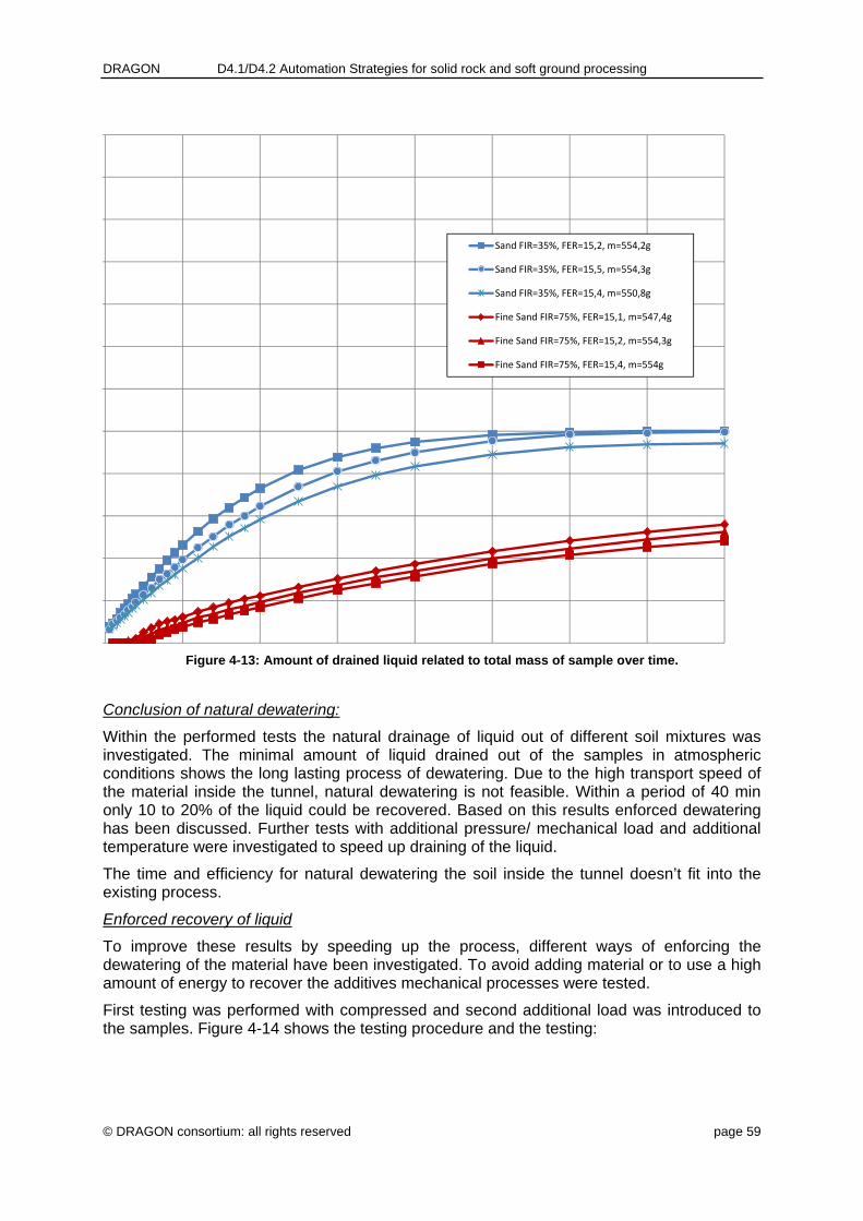
DRAGON D4.1/D4.2 Automation Strategies for solid rock and soft ground processing
© DRAGON consortium: all rights reserved page 59
Figure 4-13: Amount of drained liquid related to total mass of sample over time.
Conclusion of natural dewatering:
Within the performed tests the natural drainage of liquid out of different soil mixtures was investigated. The minimal amount of liquid drained out of the samples in atmospheric conditions shows the long lasting process of dewatering. Due to the high transport speed of the material inside the tunnel, natural dewatering is not feasible. Within a period of 40 min only 10 to 20% of the liquid could be recovered. Based on this results enforced dewatering has been discussed. Further tests with additional pressure/ mechanical load and additional temperature were investigated to speed up draining of the liquid.
The time and efficiency for natural dewatering the soil inside the tunnel doesn’t fit into the existing process.
Enforced recovery of liquid
To improve these results by speeding up the process, different ways of enforcing the dewatering of the material have been investigated. To avoid adding material or to use a high amount of energy to recover the additives mechanical processes were tested.
First testing was performed with compressed and second additional load was introduced to the samples. Figure 4-14 shows the testing procedure and the testing:
Sand FIR=35%, FER=15,2, m=554,2g
Sand FIR=35%, FER=15,5, m=554,3g
Sand FIR=35%, FER=15,4, m=550,8g
Fine Sand FIR=75%, FER=15,1, m=547,4g
Fine Sand FIR=75%, FER=15,2, m=554,3g
Fine Sand FIR=75%, FER=15,4, m=554g

DRAGON D4.1/D4.2 Automation Strategies for solid rock and soft ground processing
© DRAGON consortium: all rights reserved page 60
Figure 4-14: Forced dewatering testing procedure.
Results
Figure 4-15 shows the amount of liquid drained out of the sample as an amount of the liquid mixed inside the sample. Typical ground foam mixtures sand and fine sand with different FIR) were investigated.
Weight
Plexiglass cylinder
Punch
Foam / ground mixture
Sieve
Liquid outlet
Pan

DRAGON D4.1/D4.2 Automation Strategies for solid rock and soft ground processing
© DRAGON consortium: all rights reserved page 61
Figure 4-15: Forced dewatering testing procedure.
Figure 4-16 shows the amount of liquid drained out of the sample as an amount of the total mass mixed inside the sample. Typical ground foam mixtures sand and fine sand with different FIR) were investigated.
, , , ,
Sand, w=12%, FER=14,7, FIR=35%, m=499,1g
Feinsand, w=12%, FER=14,4, FIR=75%, m=501,1g

DRAGON D4.1/D4.2 Automation Strategies for solid rock and soft ground processing
© DRAGON consortium: all rights reserved page 62
Figure 4-16: Forced dewatering testing procedure.
Conclusion of enforced dewatering:
Enforcing the dewatering and recovering of the added material inside the tunnel is limited by the speed of excavation and amount of material transported with the conveyor belt. Therefore the first practical approach is to squeeze the excavated material with a second belt and top rollers inside the gantry system and to collect the recovered slurry in a bin under the conveyor belt. Therefore the top belt needs to be perforated to guide the liquid to both sides of the belt conveyor ready to be pumped into the working chamber via pumps. Therefore an additional line (see figure 4-10) of material to be introduced into the working chamber needs to be added. The amount of recovered additives depends strictly to the ratio of foam related to the amount of soil particle inside the mixture. In geologies with high permeability higher FIR values are needed, but more additives can be recovered by practical approaches.
4.3.4 Quality control of conditioned soil
Material flow on conveyor belt is usually being surveyed at all times. Depending on actually excavated soil, e.g. clay, a sample will be bypassed for a chemical analysis. If material is usable for other purposes, it will be processed and prepared for other industrial needs.
The immediate on-site use of excavated material such as solid rock aggregates for concrete production or gravel for backfilling is an internal process. That means no guidelines for waste disposal or other regularities need to be taken into account due to the direct use of the quarried material inside the tunnel.
Sand, w=12%, FER=14,7, FIR=35%, m=499,1g
Feinsand, w=12%, FER=14,4, FIR=75%, m=501,1g

DRAGON D4.1/D4.2 Automation Strategies for solid rock and soft ground processing
© DRAGON consortium: all rights reserved page 63
When conveying the material outside, however, in order to prepare it as trade goods for other industrial sectors, several EU and national guidelines must be considered.
For being able to use this excavated material in other sectors of industry, two cases must be distinguished to meet the corresponding EU guidelines. Only if these preconditions are met the planned utilization of excavated material is possible!
While the main product is the tunnel itself, we can define the following scenarios for the excavated material:
1) Side product: Excavated material that can be used directly or slightly modified by means of common standard processing for other sectors of industry.
2) Remaining material is declared as waste in the first place. But, we are having the intention that after a profound analysis and, if necessary, a subsequent processing, parts of this compounds will be a usable product for industry needs.
For both points, the industrial requirements and the corresponding market must be known. Furthermore, the criteria of this market must be known as well, i.e. where is the market, under which circumstances the product is of interest for this market and could it be used there as primary material.
3) Waste that cannot be treated to become a marketable product. In this case, only landfilling or other forms of recycling remain. The criteria’s of material for landfill are regionally different, but improvement of added material to a minimum and recovering of added agents during EPB tunneling will improve the quality of the material.

DRAGON D4.1/D4.2 Automation Strategies for solid rock and soft ground processing
© DRAGON consortium: all rights reserved page 64
5 Exploitable Knowledge and its Use
The concrete production plant on top of a mobile / non mobile gantry system will be a unique opportunity to reduce the transport volume in and out of the tunnel. In combination with the load measurement of the discs and correlation with the hardness of the excavated rock an automated aggregates plant can be installed. The correlation has to be updated daily from a geologist.
Separation plants on top of gantry systems. The opportunity is to minimize the prower for material transport. Today the complete slurry circuit with a value of 10%-20% excavated material needs to be pumped throught the whole tunnel. If we separate the material flow between slurry (water / bentonite / fines) and grain sizes beyond 1 mm on a conveyor belt the power consumption will be improved, the dimension of the separation plant can be reduced in volume per hour and therby the necessary power.
Washing plant for separated material out of a mixshield. As shown in the deliverable tunneling in the Rhine valley will produce useful concrete aggregates to be sold or directly used inside the project.
Recovery of foaming agent. The performed lab tests give a starting point for further developing. This unique idea, in combination with the chemical analyzing (described in DWP 3 and WP5) may lead to an improved reuse af the excavated material out of tunnels and reduce the amount of foaming agents.

DRAGON D4.1/D4.2 Automation Strategies for solid rock and soft ground processing
© DRAGON consortium: all rights reserved page 65
6 Conclusion
Within the last 20 years, spoil management has gained importance on large construction sites. Tunnel boring machine (TBM) excavated material, or muck, if suitable, can be processed in high-quality aggregates for on-site or external uses.
In this Deliverable “Automation strategies for solid rock and softground processing”, we have discussed the automated material processing on hard-rock and soft-ground TBMs in tunnels.
After the executive summary, we described in chapter 2 “Different types of Tunnel Boring Machines”, the various types of tunnel boring machine existing, mainly hard (or solid) rock (gripper and shield TBMs) and softground (mixshield and EPB). Since each of these technologies differs from one another, they require their own, respective and adapted automation process strategies.
Chapter 3 entitled “Technological strategy for automated solid rock processing” exclusively focuses on the process automation on hard rock TBMs. The nature of hard rock tunneling is the stable excavation face. Therefore the material transport out of the working chamber is performed by mechanical transport systems like screw conveyors or belt conveyors. Beside sprayed water, to reduce the dust production, no additional agents must be added.
Chapter 3 starts with a description of the relevant and minimal raw material processing requirements as well as the quality criteria for on-site use of hard-rock TBM muck as aggregate for various products. Basically, muck quality is determined following a quick, accurate and reproducible laboratory method developed by Cédric Thalmann during his PhD thesis. This test is based on the petrography and the hardness (Breakability test, Point-Load-Index and Los-Angeles-Index) of the material excavated.
Following the description of muck quality requirements and their measurement methods and controls, we defined the frames of a material processing plant for fast and online separation between useful and non-useful resources by:
Characterizing TBM muck (geometry and physics). The raw material contains high levels of fines (<0.063mm). This fraction has to be kept homogeneous and to a minimum.
Presenting available raw material processing alternatives (dry and wet). Wet processing requires larger infrastructures than dry processing. Moreover, it produces mud, which has to be landfilled.
Choosing the most adequate aggregate production method to install on a TBM back-up. Dry processing is the most adequate processing solution since it only requires a stacked screening unit.
Describing which aggregates can be produced. We focus on the production of tunneling relevant and basic uses: shotcrete aggregates, in-situ concrete aggregates, invert filling aggregates and mortar aggregates for back filling (annular gap).
Describing the various steps of aggregate processing as summarized in Figures 3-12, 3-15 and 3-16.

DRAGON D4.1/D4.2 Automation Strategies for solid rock and soft ground processing
© DRAGON consortium: all rights reserved page 66
We then studied the effect of spacing on the size and depth of TBM chips. Actually, the freshly excavated TBM muck can be classified in two main grain fractions: 0/10 mm (35 to 65%) and 10/16 mm (50 to 75%). These grain fractions match those required by our chosen on-site purposes. Therefore, we do not see any needs of changing spacing settings.
Before illustrating our knowledge by the Brenner Base Tunnel (BBT) example, we exposed different considerations for designing the prototype such as:
Proportion of TBM muck used during tunneling. Only 27% of the total material excavated will be processed into high-quality aggregates.
Definition and dimensioning of the processing components. Dry processing only requires a stacked sieve unit with minimal the following minimal characteristics: 8m2, 30kw, 6.0 x 2.5 x 2.5m
Moreover, a first 3D draw of the processing unit prototype was presented. The hardness, brittleness of the natural material, the grain size of the excavated material and the mica content define the ability to use this material for in tunnel processing. The physical parameters of the tunnel face must be evaluated by measuring the disc cutter load (WP3), comparing it with TBM data and new developed onside rock hardness indicators (WP3). The different grain sizes, necessary for different types of concrete in the specific area of hard rock tunnelling can be produced by production plants inside the tunnel. The complete process requires:
a) Knowledge about calibrating measured parameters
b) Necessary amount of concrete for shot crete / lining or invert filling and therefore aggregates to use
c) Separation plants and concrete mixing areas.
d) Detailed know how of useable aggregates from excavated material, like max. mica content etc.
The chapters are describing this knowledge and design the necessary equipment as a concept. The developed sensors of WP 3 and the descripted strategy to use the excavated material in the tunnel can be defined as a practical approach to be defined on a real project together with the project owner and the construction company. In WP 5 demonstration of different sensors will be performed.
Finally, chapter 4 described automated processing strategies for softground Tunnel boring machines. The nature of tunnelling in softground geology is defined by the instable excavation face. Therefore additional agents need to be added. Chapter 4 includes two main sections discussing new automation systems for mixshield and EPB (Earth Pressure Balance) TBMs, respectively. In each section, the up-to-date processes and quality criteria for automated processing of softground material compounds (e.g., Bentonite and gravel) are presented.
The nature of tunnelling with slurry shield / Mix shield in high permeable material is defined by the instable excavation face. Therefore additional agents need to be added inside the excavation chamber. This bentonite, added to stabilize the tunnel face, is completely mixed to the excavated material. Bentonite is normally separated from the material and water in so-called large separation plant outside the tunnel. A new way of slurry classification based on electro-coagulation is being developed by Herrenknecht. It has been fully integrated into the already existing separation process (separation plant) as exemplified by the Karlsruhe tunneling project.

DRAGON D4.1/D4.2 Automation Strategies for solid rock and soft ground processing
© DRAGON consortium: all rights reserved page 67
The automated processing strategy will be to separating the useful material, usually gravel and sand, inside the tunnel by washing it on a gantry based separation plant. First lab tests have been performed to show the basics of the process and application cases. The time for bentonite coagulation inside the slurry will not allow this process to occur inside the slurry circuit, but to avoid additional pollution of resources like water. Due to the project definition of processing excavated material inside the tunnel for further use, this process of separating water from bentonite with electro coagulation will not be further developed.
The nature of tunnelling with EPB in less permeable material is defined by the instable excavation face as well. Therefore the excavated material will be mixed with agents needed to reduce the power for tunnelling. These agents can be water, injected inside the working chamber or foam injected inside the working chamber and / or screw conveyor. To define the useful material for industry or further processing a chemical analysing was developed in WP3. This process will be placed beside the conveyor belt. A first prototype will be described and demonstrated in WP5.
Their recovery of injected products was investigated in laboratory by testing the natural drainage of liquid out of various soil mixtures. First results show that dewatering is a long process under atmospheric conditions. Due to the project definition of processing excavated material inside the tunnel for further use, this process of separating agents from the mixed ground will not be further developed.
In conclusion, this text presented the different and innovative automated
technologies for processing high-quality aggregates on hard-rock TBMs and
separating Bentonite, water and/ or other additives from rocky material during
softground driving for on-site and industrial purposes.

DRAGON D4.1/D4.2 Automation Strategies for solid rock and soft ground processing
© DRAGON consortium: all rights reserved page 68
7 References
1. Bundesverband Naturstein-Industrie, 1993. Bauen mit Splittbeton. Bundesverband Naturstein-Industrie e.V., Bonn.
2. Dubuisson, 1959. Encyclopédie classique de la construction et du bâtiment. Exécution de la construction traditionnelle. Titre-II, 3e partie, Paris.
3. Kruse M. and Weber R., 1993. Beton aus TBM-Ausbruchmaterial. Aufbereitungs- und Betonvorversuche im Hinblick auf AlpTransit Gotthard. SIA-113, 47, 1995, p. 6-10.
4. Thalmann C., 1996. Beurteilung und Möglichkeit der Wiederverwertung von Ausbruchmaterial aus dem maschinellen Tunnelvortrieb zu Betonzuschlagsstoffen. ETH Dissertation No. 11721.
5. Thewes, Budach, WTC 2011: Soil Conditioning for EPB Shields: New Results from Research on Foams and Soil-Foam-Mixtures
6. Herrenknecht AG webpage
7. AFNOR P 18-579, Granulats - Détermination des coefficients d'abrasivité et de broyabilité. Association Française de normalisation, Paris.
8. Büchi E. and Thalmann C., 1994: Reuse of TBM much versus cutter spacing. TBM symposium Lucia

DRAGON D4.1/D4.2 Automation Strategies for solid rock and soft ground processing
© DRAGON consortium: all rights reserved page 69
8 Annex
Figure 8-1: Design concept of the in-situ concrete production plant inside tunnel (side-view 1)
Figure 8-2: Design concept of the in-situ concrete production plant inside tunnel (side-view 2)

DRAGON D4.1/D4.2 Automation Strategies for solid rock and soft ground processing
© DRAGON consortium: all rights reserved page 70
Figure 8-3: Dimensions of the concrete production plant (side-view)
Figure 8-4: Dimensions of the concrete production plant (cross-sectional view)

DRAGON D4.1/D4.2 Automation Strategies for solid rock and soft ground processing
© DRAGON consortium: all rights reserved page 71
Figure 8-5: Assembly of the concrete production plant (side-view 1)
Figure 8-6: Assembly of the concrete production plant (bottom view)

DRAGON D4.1/D4.2 Automation Strategies for solid rock and soft ground processing
© DRAGON consortium: all rights reserved page 72
Figure 8-7: Assembly of the concrete production plant (side-view 2)
Figure 8-8: Output connections of the concrete production plant