d.3.5 new visual signs and elements - inframix eu project€¦ · new visual signs and elements due...
TRANSCRIPT

INFRAMIX V6.0
Grant Agreement Number: 723016
Project acronym: INFRAMIX
Project full title: INFRAMIX - Road INFRAstructure ready for MIXed vehicle traffic
flows
D.3.5
New visual signs and elements
Due delivery date: 31/05/2019 Actual delivery date: 16/07/2019
Organization name of lead participant for this deliverable: AAE
Project funded by the European Union’s Horizon 2020 Research and Innovation Programme (2014 – 2020)
Project co-funded by the European Commission within Horizon 2020
Dissemination level
PU Public X
PP Restricted to other programme participants
RE Restricted to a group specified by the consortium
CO Confidential, only for members of the consortium

16/07/2019 2 V6.0
Document Control Sheet
Deliverable number: 3.5
Deliverable responsible: AAE
Work package: WP3
Editor: David Porcuna
Author(s) – in alphabetical order
Name Organisation E-mail
Anna Carreras Coch AAE [email protected]
Xavier Daura Albeldo AAE [email protected]
David Porcuna Sanchez AAE [email protected]
Juan J. Salguero AAE [email protected]
Anna-Maria Adaktylos ASF [email protected]
Jacqueline Erhart ASF [email protected]
Yannick Wimmer ASF [email protected]
Dr. Stefaan Duym BMW [email protected]
Document Revision History
Version Date Modifications Introduced
0.0 29.10.2018 ToC + Partners responsibilities AAE
0.1 6.11.2018 Visual Requirements Scenario 1 and Scenario 3, available infrastructure in Spain
AAE
0.2 9.11.2018 BMW Navigation screens Calibration sign for the German test site
BMW
0.3 29.11.2018 Updates on the Use Cases visual requirements ICCS
1.0 25.01.2018 Updates on the Spanish regulations and Designing process section
AAE
1.1 06.02.2019 Updates on the Visual requirements based on ICCS and BMW feedback
AAE
1.2 25.02.2019 Updates on the Visual requirements based on the feedback from WP3 meetings
AAE
1.3 11.03.2019 Updates based on ICCS feedback. First version of Section 1 complete.
AAE
2.0 18.04.2019 Survey Results AAE
2.1 23.04.2019 New visual sign final design AAE
3.0 24.04.2019 European and Austrian regulations. ASFINAG test-site
ASF
5.0 06.05.2019 Final version for review AAE
5.1 23.05.2019 Final version reviewed by TOM (official reviewer) and FOK AAE
5.4 26.06.2019 Feedback from ASF, ENI, SIE, TOM and VIF AAE
6.0 12.07.2019 Approval from all the partners AAE
Legal Disclaimer
The information in this document is provided “as is”, and no guarantee or warranty is given that the information is fit for any particular purpose. The above referenced consortium members shall have no liability for damages of any kind including without limitation direct, special, indirect, or consequential damages that may result from the use of these materials subject to any liability which is mandatory due to applicable law. Content reflects only the authors’ view, and the European Commission is not responsible for any use that may be made of the information it contains. © 2019 by INFRAMIX Consortium.
16/07/2019 3 V6.0
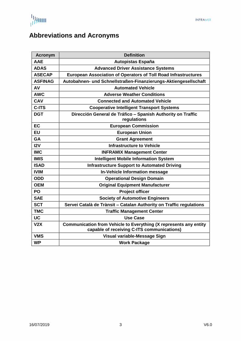
Abbreviations and Acronyms
Acronym Definition
AAE Autopistas España
ADAS Advanced Driver Assistance Systems
ASECAP European Association of Operators of Toll Road Infrastructures
ASFINAG Autobahnen- und Schnellstraßen-Finanzierungs-Aktiengesellschaft
AV Automated Vehicle
AWC Adverse Weather Conditions
CAV Connected and Automated Vehicle
C-ITS Cooperative Intelligent Transport Systems
DGT Dirección General de Tráfico – Spanish Authority on Traffic regulations
EC European Commission
EU European Union
GA Grant Agreement
I2V Infrastructure to Vehicle
IMC INFRAMIX Management Center
IMIS Intelligent Mobile Information System
ISAD Infrastructure Support to Automated Driving
IVIM In-Vehicle Information message
ODD Operational Design Domain
OEM Original Equipment Manufacturer
PO Project officer
SAE Society of Automotive Engineers
SCT Servei Català de Trànsit – Catalan Authority on Traffic regulations
TMC Traffic Management Center
UC Use Case
V2X Communication from Vehicle to Everything (X represents any entity capable of receiving C-ITS communications)
VMS Visual variable-Message Sign
WP Work Package
16/07/2019 4 V6.0
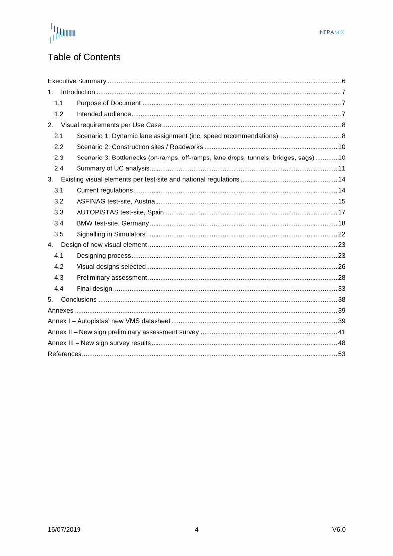
Table of Contents Executive Summary ................................................................................................................................ 6
1. Introduction ...................................................................................................................................... 7
1.1 Purpose of Document ............................................................................................................. 7
1.2 Intended audience ................................................................................................................... 7
2. Visual requirements per Use Case .................................................................................................. 8
2.1 Scenario 1: Dynamic lane assignment (inc. speed recommendations) .................................. 8
2.2 Scenario 2: Construction sites / Roadworks ......................................................................... 10
2.3 Scenario 3: Bottlenecks (on-ramps, off-ramps, lane drops, tunnels, bridges, sags) ............ 10
2.4 Summary of UC analysis ....................................................................................................... 11
3. Existing visual elements per test-site and national regulations ..................................................... 14
3.1 Current regulations ................................................................................................................ 14
3.2 ASFINAG test-site, Austria .................................................................................................... 15
3.3 AUTOPISTAS test-site, Spain ............................................................................................... 17
3.4 BMW test-site, Germany ....................................................................................................... 18
3.5 Signalling in Simulators ......................................................................................................... 22
4. Design of new visual element ........................................................................................................ 23
4.1 Designing process ................................................................................................................. 23
4.2 Visual designs selected ......................................................................................................... 26
4.3 Preliminary assessment ........................................................................................................ 28
4.4 Final design ........................................................................................................................... 33
5. Conclusions ................................................................................................................................... 38
Annexes ................................................................................................................................................ 39
Annex I – Autopistas’ new VMS datasheet ........................................................................................... 39
Annex II – New sign preliminary assessment survey ........................................................................... 41
Annex III – New sign survey results ...................................................................................................... 48
References ............................................................................................................................................ 53

16/07/2019 5 V6.0
List of Figures Figure 1 – Different European signals to advice to leave a lane .......................................................... 10 Figure 2 – Example of lane-change advice in-vehicle .......................................................................... 11 Figure 3 – Some examples of signalling ............................................................................................... 15 Figure 4 – Gantries equipped with ADAS ............................................................................................. 16 Figure 5 – ASFINAG “Unterwegs” app displaying the INFRAMIX test-site in different languages ....... 16 Figure 6 – IMIS trailer on the ASFINAG motorway (diagrammed) ....................................................... 17 Figure 7 – Empty display frame with BMW logo and INFRAMIX logo .................................................. 18 Figure 8 – Icon for road works .............................................................................................................. 18 Figure 9 – Icons for the lane state (closed versus open) ...................................................................... 19 Figure 10 – Library of icons for speed limits ......................................................................................... 19 Figure 11 – Library of icons for speed advice ....................................................................................... 20 Figure 12 – Library of icons for distance control ................................................................................... 20 Figure 13 – Icons for a recommendation to change lane ..................................................................... 21 Figure 14 – Icon for a dedicated lane for autonomous vehicles ........................................................... 21 Figure 15 – Icons for slow versus fast acceleration behavior ............................................................... 21 Figure 16 – Example of a navigation display with all 8 fields filled ....................................................... 22 Figure 17– German sign for positional calibration of AVs ..................................................................... 22 Figure 18 – State-of-Art signs for Automated Driving ........................................................................... 23 Figure 19 – State-of-the-art signs for Automated Driving ..................................................................... 24 Figure 20 – Eleven designs presented to the Consortium .................................................................... 25 Figure 21 – Figures from the first design .............................................................................................. 27 Figure 22 – Figures from the second design ........................................................................................ 27 Figure 23 – Figures from the third design ............................................................................................. 28 Figure 24 – Participation by gender ...................................................................................................... 29 Figure 25 – Participation by age ........................................................................................................... 29 Figure 26 – Participation by country ..................................................................................................... 30 Figure 27 – Choices of the designs ...................................................................................................... 30 Figure 28 – Participants’ initial choice ................................................................................................... 30 Figure 29 – Results of the previous question ........................................................................................ 31 Figure 30 – Results of the previous question ........................................................................................ 31 Figure 31 – Results of the previous question ........................................................................................ 32 Figure 32 – Participants’ final choice .................................................................................................... 32 Figure 33 – Dedicated lane for AV’s – final design ............................................................................... 33 Figure 34 – Physical panels at highway entries, final design ............................................................... 34 Figure 35 – Physical panels in the highway entries, final design.......................................................... 35 Figure 36 – VMS final design ................................................................................................................ 36 Figure 37 – Temporary physical panels – final design ......................................................................... 36 Figure 38 – New sign on asphalt and gantries VMS, final design ........................................................ 37 Figure 39 – New sign in vehicle, final design ........................................................................................ 37
List of Tables Table 1 – Scenario 1, Use Case 1 ........................................................................................................ 11 Table 2 – Scenario 1, Use Case 2 ........................................................................................................ 12 Table 3 – Scenario 1, Use Case 3 ........................................................................................................ 12 Table 4 – Scenario 2, Use Case 1 ........................................................................................................ 12 Table 5 – Scenario 2, Use Case 2 ........................................................................................................ 12 Table 6 – Scenario 3, Use Case 1 ........................................................................................................ 12 Table 7 – Scenario 3, Use Case 2 ........................................................................................................ 13 Table 8 – Scenario 3, Use Case 3 ........................................................................................................ 13 Table 9 – Location of the gantries in the Austrian test-site ................................................................... 15 Table 10 – Location of the VMSs in the Spanish test-site .................................................................... 17 Table 11 – List of contacted institutions ................................................................................................ 29

16/07/2019 6 V6.0
Executive Summary
The EU project, INFRAMIX, aims to prepare the road infrastructure to support the coexistence
of conventional and automated vehicles, targeting to the transition period when the number of
automated vehicles will gradually increase, handle the transition period and become the basis
for future automated transport systems. In order to ensure uninterrupted, predictable, safe and
efficient traffic; the key outcome will be a “hybrid” road infrastructure concept after defining the
necessary upgrades and adaptations of the current roads infrastructure as well as designing
and testing, physical and digital elements using novel technologies. In order to provide precise
solutions, INFRAMIX project works on three specific scenarios, “dynamic lane assignment”,
“roadworks zones” and “bottlenecks”.
This deliverable includes ways of informing all types of vehicles, conventional and automated,
with the control commands issued by the road operators in order to manage traffic with
efficiency and safety criteria in “hybrid” designed infrastructures. Also, the deliverable
analyses the available traffic signs and their regulation and the requirements of new visual
signs that fulfil the three INFRAMIX specific scenarios.
The fundamental result will be the proposal of new visual signs that complete the gap between
currently existing signage and the one needed in the aforementioned scenarios.
Chapter 2 analyses the visual requirements per use case in the three specific scenarios.
Chapter 3 describes the traffic signage regulation applicable in the INFRAMIX test-sites as
well as the physical, in-vehicle and simulator visual signs presently available in them. Chapter
4 presents different proposals for the new visual signs and the results of the survey conducted
as preliminary assessment with the objective of selecting just one of them for the user
appreciation evaluation of WP5. The last chapter consists of the document conclusions.
16/07/2019 7 V6.0
1. Introduction
1.1 Purpose of Document An important outcome of the INFRAMIX project is the design and implementation of new elements for the physical and the digital infrastructures that will be required in the context of mixed traffic. In particular, if we consider the coexistence of conventional vehicles, connected and automated vehicles at least for the next 30 years, we will have to think of signs that can be either projected on Variable Messages Signs (VMS) or static panels on the roads, embedded on maps, in-vehicle, or communicated to the automated cars without the need of a visual representation. Indeed, the purpose of this document is to report the work conducted within T3.5 Definition of “new” visual signs and elements which consists in the following: first to analyse the visual requirements of the project per Use Case, and based on current regulations and existing signalling, design and implement any required new sign. In order to complete this task, a preliminary assessment of the new designs will be conducted. A complete evaluation on user appreciation of the outcomes of this task will be done in T5.2.
1.2 Intended audience This is a public Deliverable with the intention to reach as many readers as possible. The presented results can be used in the future on real roads and for discussions with CEN TC226 [1]. We aim to convince Traffic Regulators and Legislators and specially all the promoters of signalling harmonization among Europe of our proposal. Of course, we also need to involve OEMs, Services Providers, Infrastructure Providers and Roads Operators as the main users of these new designs, which are well represented in the INFRAMIX Consortium (BMW, TOMTOM, SIEMENS, ASFINAG, Autopistas).

16/07/2019 8 V6.0
2. Visual requirements per Use Case
This chapter aims at identifying the visual needs of each Use Case of the project. It addresses each Scenario and concludes with a summarizing table. A detailed analysis of each Use Case is included in Deliverable D2.1, known as “Requirements catalogue from the status quo analysis”1, which has been used as the starting point for this section. The first visual requirement identified for the three scenarios (and even for any mixed traffic scenario) is the identification of the infrastructure capabilities before entering a road segment. In D2.1 this was referred to as the infrastructure automation level, but at this point of the project the best way to identify the capabilities would be through the Infrastructure Support to Automated Driving (ISAD) levels presented in [2][3] and further refined within the T5.4 of the project. The main reasons for this requirement are the following:
o To indirectly recommend the use of a nomadic device to communicate with the TMC by informing on the IMC functionalities related to I2V
o To raise awareness that the vehicle will share several anonymized info like its SAE level, location, expected route etc. with the infrastructure
o To raise awareness that digital messages will be sent by the IMC via ITS-G5 or Cellular connectivity (for connected vehicles)
o awareness that the traffic will be mixed Regarding the support and format of this information, we envision that this information could be an I2V message informing the vehicles about ISAD level of the entering a road segment, since the ISAD level could be dynamically upgraded/degraded according to the ongoing situation (weather conditions, accidents, roadworks, etc.).
2.1 Scenario 1: Dynamic lane assignment (inc. speed recommendations)
For all the Use Cases of Scenario 1, before entering the highway there are a number of actions detailed in D2.1 with their corresponding visual requirements that need to be considered. TMC should inform the road users about the infrastructure capability to dynamically assign a lane to AVs before entering the highway and while using the roadway. This shall be done via physical and digital infrastructure support. The first could be included next to the name of the road on the respective motorway entrance signs, while the second could be implemented in a similar way to the ISAD level, as a pictogram on the static digital map of the road via an “In-Vehicle Information” digital message (IVIM)[4]. Unless a lane is dedicated specifically to automated vehicles and therefore closed to other traffic, the information which ISAD level a given road section has is only relevant to automated vehicles. Therefore, the information does not necessarily need to be provided in visual form so that the human drivers can get this information. However, it is relevant to automated vehicles, and therefore has to be provided in digital form that the AVs can easily detect and implement in the on-board decision making.
1 INFRAMIX, H2020 EU Project, GA No. 723016, Deliverable D2.1 “Requirements catalogue from the status quo analysis”. Available online: http://www.inframix.eu/wp-content/uploads/INFRAMIX_D2.1-Requirements-catalogue-from-the-status-quo-analysis.pdf
16/07/2019 9 V6.0
Use Case 1: Real-time lane assignment under Dynamic Penetration Rate of Automated Vehicles (AVs) For Use Case 1, we need to define the adequate means and ways of I2V communication to inform the automated vehicles about the time intervals during which and vehicle groups which are permitted to use the lane. Generally, whether or not a lane is closed to non-AV traffic has to be shown in a form that a human driver can understand, be the reason of closing that the lane is dedicated to AV traffic or any other reason. Additional information such as that this lane is open to AVs, the time intervals during which only AVs are allowed on this lane, speed limits or speed recommendations etc. needs to be provided in digital form so that the information can be detected easily by the AV and be implemented in the on-board decision making. Finally, the TMC should inform the road users about the duration of the transition period which is defined between the time that they receive the information to the time that the lane will be actually activated or deactivated. This information should be indicated as simple as possible as not to confuse the driver with too complex messages. An alternative to informing the driver about temporal start and end would be to reduce the speed limit temporarily (in order to facilitate and guarantee safety in the required number of lane changes), but this still needs to be validated through simulation by the project. Indeed, the protocol for setting the Dedicated Lane is not completely finished to stablish its corresponding visual requirements, but for the reasons stated above we do not foresee to need a new sign for this transition period. Use Case 2: Exceptional traffic situations-adverse weather conditions as an example Regarding Use Case 2, the first requirement is that CAVs should be informed that the TMC can provide information about adverse weather conditions (AWC) related to the automated levels. This is one of the capabilities identified by the ISAD levels, and thus we would not need a further sign for this. Regarding the type of AWC information that should be provided it is difficult to standardize it. Visual signs already exist: frost, snow, rain. The relevance for autonomous drivers strongly depends on the individual OEM concepts of automated driving so the interpretation has to be done by each type of car anyway. But what could help would be to quantify these signs, e.g. visibility due to fog limited to 50m. This could be done digitally, and no visual elements would be required as it would be only relevant for the vehicle. Finally, regarding the Dedicated Lane it would be particularly important to inform about a speed recommendation - in order to guarantee a certain traffic flow- for the lane. One can imagine certain traffic scenarios, AWC, being one example, in which the TMC does not see the necessity to advice reduced speed – but due to the AVs internal decision making AVs would reduce speed and increase distance gaps, more than would actually be required by the circumstances. In this case the AV should lose its clearance for the dedicated lane – and would have to leave the specific lane. This of course means that handover strategies to the human driver have to be in place. However, in all these scenarios the required information would be provided digitally within the vehicle for which the visual signs already exist Use Case 3: A conventional vehicle drives on a dedicated lane for AVs Regarding Use Case 3, the TMC should provide advice to leave the dedicated lane to the non-proper user. For that, there exist already signs that guide vehicles to move from one lane to another because the current lane is closed. In this case, this information would have to be
16/07/2019 10 V6.0
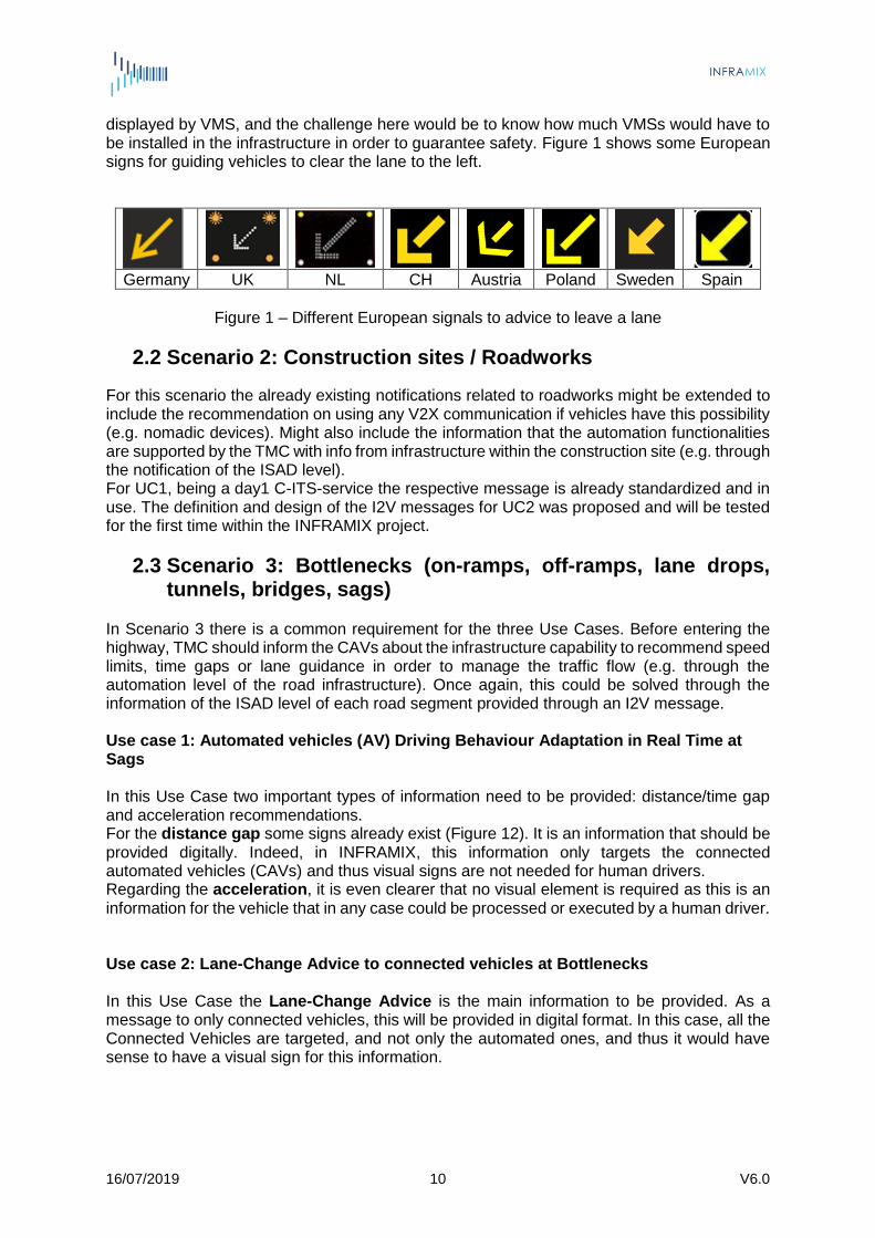
displayed by VMS, and the challenge here would be to know how much VMSs would have to be installed in the infrastructure in order to guarantee safety. Figure 1 shows some European signs for guiding vehicles to clear the lane to the left.
Germany UK NL CH Austria Poland Sweden Spain
Figure 1 – Different European signals to advice to leave a lane
2.2 Scenario 2: Construction sites / Roadworks
For this scenario the already existing notifications related to roadworks might be extended to include the recommendation on using any V2X communication if vehicles have this possibility (e.g. nomadic devices). Might also include the information that the automation functionalities are supported by the TMC with info from infrastructure within the construction site (e.g. through the notification of the ISAD level). For UC1, being a day1 C-ITS-service the respective message is already standardized and in use. The definition and design of the I2V messages for UC2 was proposed and will be tested for the first time within the INFRAMIX project.
2.3 Scenario 3: Bottlenecks (on-ramps, off-ramps, lane drops, tunnels, bridges, sags)
In Scenario 3 there is a common requirement for the three Use Cases. Before entering the highway, TMC should inform the CAVs about the infrastructure capability to recommend speed limits, time gaps or lane guidance in order to manage the traffic flow (e.g. through the automation level of the road infrastructure). Once again, this could be solved through the information of the ISAD level of each road segment provided through an I2V message. Use case 1: Automated vehicles (AV) Driving Behaviour Adaptation in Real Time at Sags In this Use Case two important types of information need to be provided: distance/time gap and acceleration recommendations. For the distance gap some signs already exist (Figure 12). It is an information that should be provided digitally. Indeed, in INFRAMIX, this information only targets the connected automated vehicles (CAVs) and thus visual signs are not needed for human drivers. Regarding the acceleration, it is even clearer that no visual element is required as this is an information for the vehicle that in any case could be processed or executed by a human driver. Use case 2: Lane-Change Advice to connected vehicles at Bottlenecks In this Use Case the Lane-Change Advice is the main information to be provided. As a message to only connected vehicles, this will be provided in digital format. In this case, all the Connected Vehicles are targeted, and not only the automated ones, and thus it would have sense to have a visual sign for this information.

16/07/2019 11 V6.0
Figure 2 – Example of lane-change advice in-vehicle Use case 3: Lane-Change Advice combined with Flow Control at Bottlenecks for all vehicles Speed limits for the main stream Flow Control should be projected physically through VMS as well as digitally for CAVs, and for both cases, the required signs already exist. In the first case, the challenge is to have a VMS per lane which is not always available in the European highways. For the Lane-Change Advice targeting CAVs, a digital format is required, and in this case, it is not even necessary to have a visual sign for this as in the previous use case, as the information should be sent directly to the vehicle.
2.4 Summary of UC analysis The following tables summarize the Visual Requirements per Use Case described so far. General legend:
Physical: physical road signage addressed to human drivers.
Digital: I2V communications.
Visual requirement: advice to be shown in vehicle’s HMI.
New sign: design of new sign needed. Table 1 – Scenario 1, Use Case 1
Physical Digital Visual requirement
New sign
ISAD X
Dedicated Lane Capability
X X X X
Dedicated Lane Criteria
X
Dedicated lane timing
X
Dedicated lane activation period
X
16/07/2019 12 V6.0
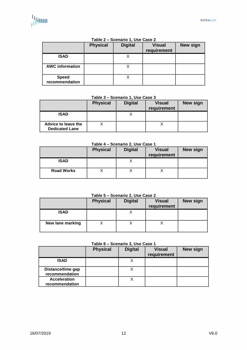
Table 2 – Scenario 1, Use Case 2
Physical Digital Visual requirement
New sign
ISAD X
AWC information X
Speed recommendation
X
Table 3 – Scenario 1, Use Case 3
Physical Digital Visual requirement
New sign
ISAD X
Advice to leave the Dedicated Lane
X X
Table 4 – Scenario 2, Use Case 1
Physical Digital Visual requirement
New sign
ISAD X
Road Works X X X
Table 5 – Scenario 2, Use Case 2
Physical Digital Visual requirement
New sign
ISAD X
New lane marking X X X
Table 6 – Scenario 3, Use Case 1
Physical Digital Visual requirement
New sign
ISAD X
Distance/time gap recommendation
X
Acceleration recommendation
X
16/07/2019 13 V6.0
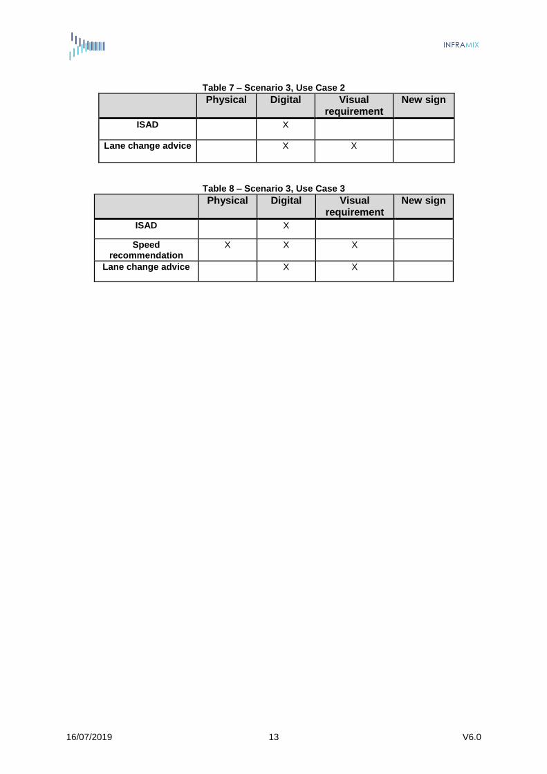
Table 7 – Scenario 3, Use Case 2
Physical Digital Visual requirement
New sign
ISAD X
Lane change advice X X
Table 8 – Scenario 3, Use Case 3
Physical Digital Visual requirement
New sign
ISAD X
Speed recommendation
X
X X
Lane change advice X X

16/07/2019 14 V6.0
3. Existing visual elements per test-site and national regulations
3.1 Current regulations
Europe
On the European level the CEN/TC 226 “Road infrastructure” [1] has created a new working group 12 considering the standardization of “Road interaction – ADAS/Autonomous vehicles”. The aim of this activity is to prepare specifications for safety, traffic control and other road equipment in, among other fields: Horizontal signs including road studs and road markings; Vertical signs including signs, cones and marker posts; Traffic lights including signals, traffic control and danger lamps [5]. ITS Platform: Variable Message Signs Harmonization PRINCIPLES OF VMS MESSAGES DESIGN [6]. In Europe, motorways are usually equipped with the highest sign and marking quality partly
due to e.g. the requirements of the EU directive on road infrastructure safety management applying to TEN-T roads [5] and are also well maintained which give automated driving systems a good possibility to position themselves on the road. According to the EU-EIP activity for facilitating automated driving report (as of Jan 2019) the automotive industry is satisfied by the quality most, if not all, European countries (EU EIP 2016). With regard to road state, given that an automated driving system could exert a finer and swifter control of a vehicle, the surface state sufficient to guarantee safety to a human driver would be enough for its automated counterpart [7] Although there is no common traffic regulation yet in place. The variety of visual sign layouts hamper the implementation of simple recognition patterns in vehicle camera software. Furthermore, there are still differences between motorways and rural and urban environments which hinder a harmonized and standardized equipment, which has to be considered in further proposals especially with respect to cost/benefit analysis.
Austria
In Austria, different regulations have to be applied to be compliant with existing law. The General Traffic Regulation in Austria (StVO-Straßenverkehrsordnung), the regulations of visual signs (StVZVO-Straßenverkehrszeichenverordnung) and the regulation of Federal Road (RVS-Richtlinien und Vorschriften für das Straßenwesen) combined with the CEN standards transformed to Austrian standards ( ÖNORM EN 12899-1, ÖNORM V 2051:2008 03 01, ÖNORM EN 12899-1, ÖNORM V 2050:2006 01 01, ÖNORM EN 12966:2015 05 01) need to be applied. Additionally, Austria is taking care of the existing ITS Directive and will consider the Delegated Act on C-ITS for digital messages. In March 2019 the first amendment to the “Automatisiertes Fahren Verordnung (AutomatFahrV) “came in to force in Austria, laying the legal basis for driver assistance systems, in particular allowing the “hands-off” usage the automated parking assistance and highway-assistance systems. Further the amendment is meant to speed up proceedings concerning test-drives for the lower level street network.
16/07/2019 15 V6.0
Spain
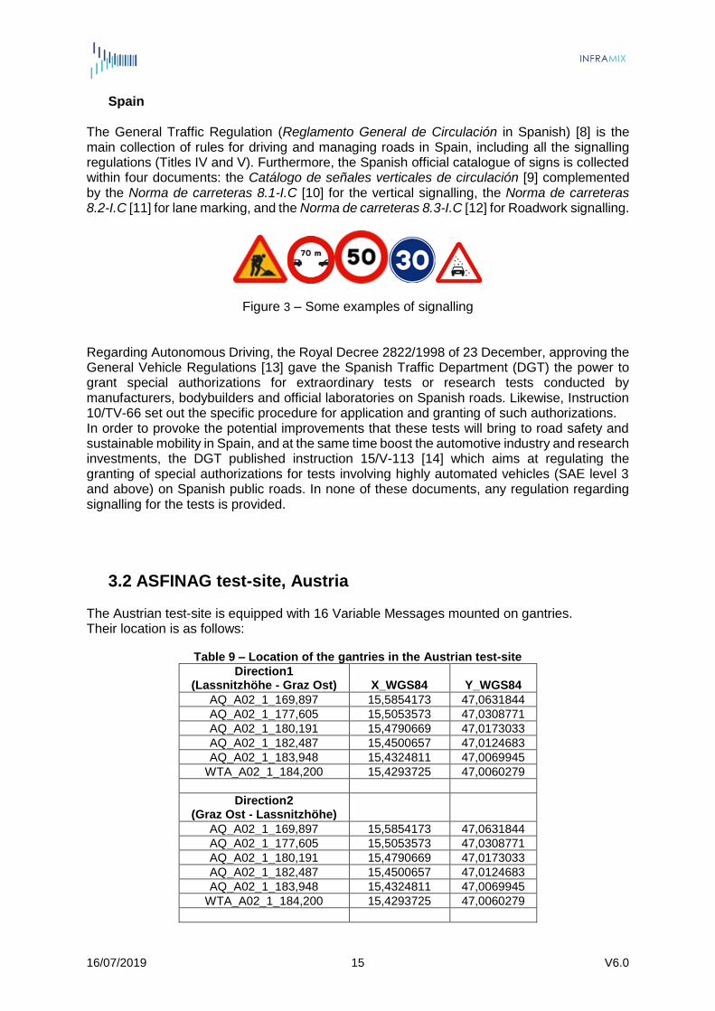
The General Traffic Regulation (Reglamento General de Circulación in Spanish) [8] is the main collection of rules for driving and managing roads in Spain, including all the signalling regulations (Titles IV and V). Furthermore, the Spanish official catalogue of signs is collected within four documents: the Catálogo de señales verticales de circulación [9] complemented by the Norma de carreteras 8.1-I.C [10] for the vertical signalling, the Norma de carreteras 8.2-I.C [11] for lane marking, and the Norma de carreteras 8.3-I.C [12] for Roadwork signalling.
Figure 3 – Some examples of signalling
Regarding Autonomous Driving, the Royal Decree 2822/1998 of 23 December, approving the General Vehicle Regulations [13] gave the Spanish Traffic Department (DGT) the power to grant special authorizations for extraordinary tests or research tests conducted by manufacturers, bodybuilders and official laboratories on Spanish roads. Likewise, Instruction 10/TV-66 set out the specific procedure for application and granting of such authorizations. In order to provoke the potential improvements that these tests will bring to road safety and sustainable mobility in Spain, and at the same time boost the automotive industry and research investments, the DGT published instruction 15/V-113 [14] which aims at regulating the granting of special authorizations for tests involving highly automated vehicles (SAE level 3 and above) on Spanish public roads. In none of these documents, any regulation regarding signalling for the tests is provided.
3.2 ASFINAG test-site, Austria The Austrian test-site is equipped with 16 Variable Messages mounted on gantries. Their location is as follows:
Table 9 – Location of the gantries in the Austrian test-site
Direction1 (Lassnitzhöhe - Graz Ost) X_WGS84 Y_WGS84
AQ_A02_1_169,897 15,5854173 47,0631844
AQ_A02_1_177,605 15,5053573 47,0308771
AQ_A02_1_180,191 15,4790669 47,0173033
AQ_A02_1_182,487 15,4500657 47,0124683
AQ_A02_1_183,948 15,4324811 47,0069945
WTA_A02_1_184,200 15,4293725 47,0060279
Direction2 (Graz Ost - Lassnitzhöhe)
AQ_A02_1_169,897 15,5854173 47,0631844
AQ_A02_1_177,605 15,5053573 47,0308771
AQ_A02_1_180,191 15,4790669 47,0173033
AQ_A02_1_182,487 15,4500657 47,0124683
AQ_A02_1_183,948 15,4324811 47,0069945
WTA_A02_1_184,200 15,4293725 47,0060279
16/07/2019 16 V6.0
Double gantry (both directions)
AQ_A02_1_172,275 / AQ_A02_2_172,275
15,5551004
47,060884
AQ_A02_1_186,000 / AQ_A02_2_186,000
15,4090582
46,9978551
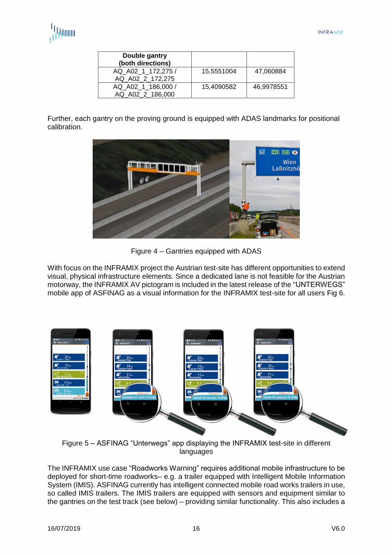
Further, each gantry on the proving ground is equipped with ADAS landmarks for positional calibration.
Figure 4 – Gantries equipped with ADAS With focus on the INFRAMIX project the Austrian test-site has different opportunities to extend visual, physical infrastructure elements. Since a dedicated lane is not feasible for the Austrian motorway, the INFRAMIX AV pictogram is included in the latest release of the “UNTERWEGS” mobile app of ASFINAG as a visual information for the INFRAMIX test-site for all users Fig 6.
Figure 5 – ASFINAG “Unterwegs” app displaying the INFRAMIX test-site in different languages
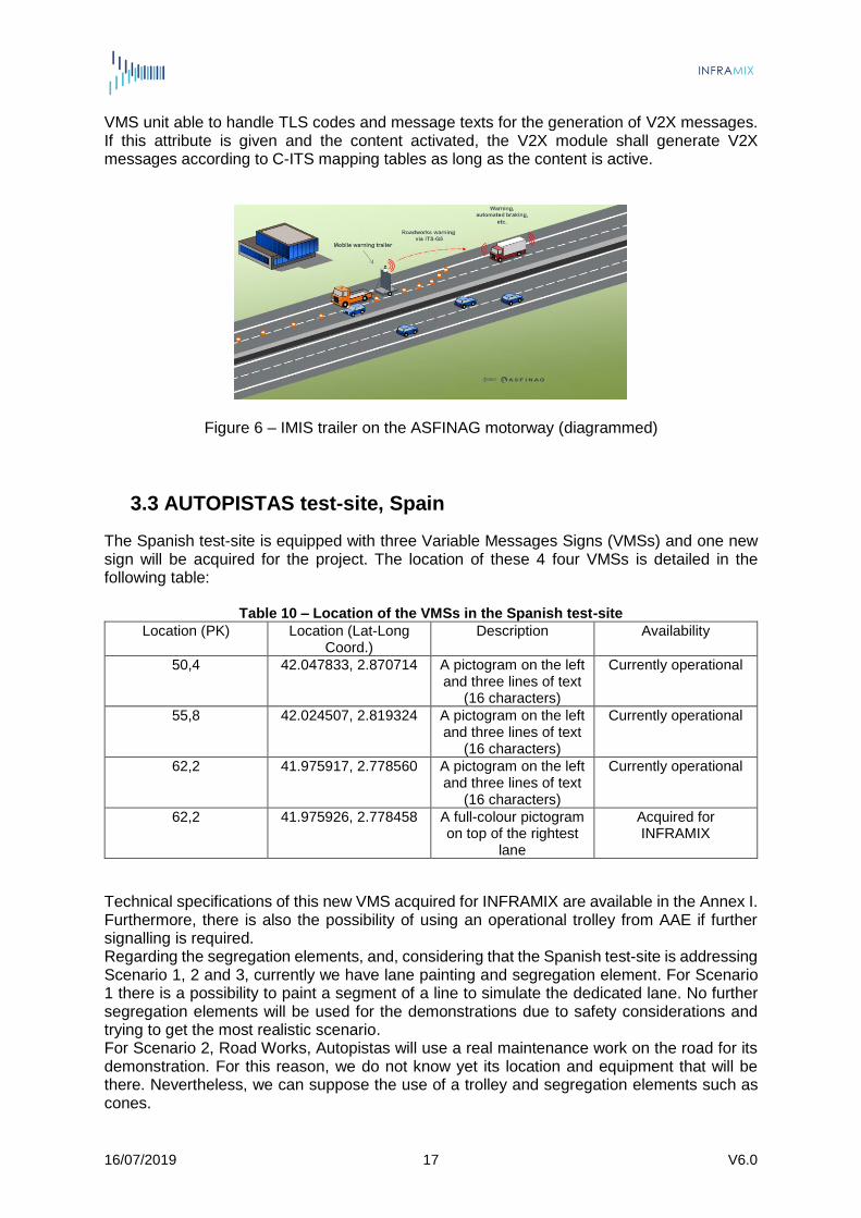
The INFRAMIX use case “Roadworks Warning” requires additional mobile infrastructure to be deployed for short-time roadworks– e.g. a trailer equipped with Intelligent Mobile Information System (IMIS). ASFINAG currently has intelligent connected mobile road works trailers in use, so called IMIS trailers. The IMIS trailers are equipped with sensors and equipment similar to the gantries on the test track (see below) – providing similar functionality. This also includes a
16/07/2019 17 V6.0
VMS unit able to handle TLS codes and message texts for the generation of V2X messages. If this attribute is given and the content activated, the V2X module shall generate V2X messages according to C-ITS mapping tables as long as the content is active.
Figure 6 – IMIS trailer on the ASFINAG motorway (diagrammed)
3.3 AUTOPISTAS test-site, Spain
The Spanish test-site is equipped with three Variable Messages Signs (VMSs) and one new sign will be acquired for the project. The location of these 4 four VMSs is detailed in the following table:
Table 10 – Location of the VMSs in the Spanish test-site Location (PK) Location (Lat-Long
Coord.) Description Availability
50,4 42.047833, 2.870714 A pictogram on the left and three lines of text
(16 characters)
Currently operational
55,8 42.024507, 2.819324 A pictogram on the left and three lines of text
(16 characters)
Currently operational
62,2 41.975917, 2.778560 A pictogram on the left and three lines of text
(16 characters)
Currently operational
62,2 41.975926, 2.778458 A full-colour pictogram on top of the rightest
lane
Acquired for INFRAMIX
Technical specifications of this new VMS acquired for INFRAMIX are available in the Annex I. Furthermore, there is also the possibility of using an operational trolley from AAE if further signalling is required. Regarding the segregation elements, and, considering that the Spanish test-site is addressing Scenario 1, 2 and 3, currently we have lane painting and segregation element. For Scenario 1 there is a possibility to paint a segment of a line to simulate the dedicated lane. No further segregation elements will be used for the demonstrations due to safety considerations and trying to get the most realistic scenario. For Scenario 2, Road Works, Autopistas will use a real maintenance work on the road for its demonstration. For this reason, we do not know yet its location and equipment that will be there. Nevertheless, we can suppose the use of a trolley and segregation elements such as cones.

16/07/2019 18 V6.0
3.4 BMW test-site, Germany
In the INFRAMIX Project a prototype In-vehicle signalling is set-up to inform the driver about the information and recommendations that are sent by the IMC over the traffic provider to the individual vehicles. Hereby the existing BMW professional Navigation screen (size 900 pixels x 450 pixels) will be used to display available messages which can be rapidly interpreted by the human driver. Since the information and recommendations consist of 8 types, the screen is divided is 8 subfields (4x2) which then can display the content of the INFRAMIX messages using predefined libraries of easily interpretable icons. Additionally, in the lower right, the logo of BMW and INFRAMIX is displayed.
Figure 7 – Empty display frame with BMW logo and INFRAMIX logo For each of the 8 available attributes to be displayed, a library of icons is used as follows: 3.4.1. Road works A boolean attribute will indicate whether the vehicle is approaching or driving through a road works zone. If the boolean is set to the value true, a sign of road works is displayed in the first frame.
Figure 8 – Icon for road works
16/07/2019 19 V6.0
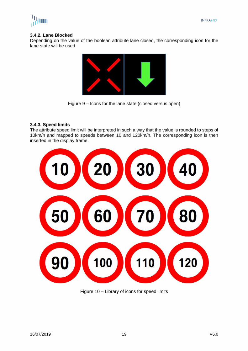
3.4.2. Lane Blocked Depending on the value of the boolean attribute lane closed, the corresponding icon for the lane state will be used.
Figure 9 – Icons for the lane state (closed versus open) 3.4.3. Speed limits The attribute speed limit will be interpreted in such a way that the value is rounded to steps of 10km/h and mapped to speeds between 10 and 120km/h. The corresponding icon is then inserted in the display frame.
Figure 10 – Library of icons for speed limits

16/07/2019 20 V6.0
3.4.4. Speed recommendations The attribute speed advice will be interpreted in such a way that the value is rounded to steps of 10km/h and mapped to speeds between 10 and 120km/h. The corresponding icon is subsequently inserted into the display frame.
Figure 11 – Library of icons for speed advice 3.4.5. Distance control The attribute time gap will be interpreted in such a way that the value is rounded to steps of 0.5s and mapped to values between 1.0 and 3.5s. The corresponding icon is subsequently inserted into the display frame.
Figure 12 – Library of icons for distance control

16/07/2019 21 V6.0
3.4.6. Advice to change lane If a recommendation to change lane is given, the present laneID and the target laneID should be compared to select the appropriate icon to change lane to the right or to the left.
Figure 13 – Icons for a recommendation to change lane
3.4.7. Indication of a dedicated lane for autonomous vehicles If the boolean attribute dedicated AV Lane is positive, the icon to indicate a dedicated AV lane must be displayed.
Figure 14 – Icon for a dedicated lane for autonomous vehicles
3.4.8. Recommendation for the acceleration behavior Dependent on the decimal value of the attribute acceleration, a corresponding icon is inserted into the frame.
Figure 15 – Icons for slow versus fast acceleration behavior

16/07/2019 22 V6.0
3.4.9. Example
If we consider for example driving into a road works zone where the present dedicated AV lane will end, speed is limited in this case to 70km/h. Due to the approach of a traffic jam tail, it is additionally recommended to drive only 40km/h and to leave a larger distance (time gap of 2.5s) between vehicles to ease lane zipping. Because of the traffic jam it does not make sense to use high accelerations but to be soft in accelerating. The following image will be correspondingly displayed in the navigation screen:
Figure 16 – Example of a navigation display with all 8 fields filled
For automated driving, a first traffic sign has been introduced on the test sites to help the positional calibration of automated vehicles. The position of the sign is precisely known and marked on a high definition map used by the automated vehicle to adjust its absolute position.
Figure 17– German sign for positional calibration of AVs
3.5 Signalling in Simulators The new signs developed for INFRAMIX will be also integrated in the relevant simulation tools.
16/07/2019 23 V6.0
4. Design of new visual element
4.1 Designing process
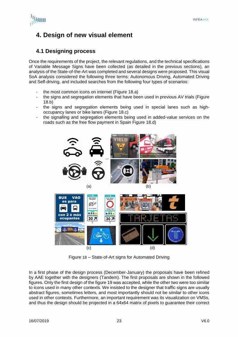
Once the requirements of the project, the relevant regulations, and the technical specifications of Variable Message Signs have been collected (as detailed in the previous sections), an analysis of the State-of-the-Art was completed and several designs were proposed. This visual SoA analysis considered the following three terms: Autonomous Driving, Automated Driving and Self-driving, and included searches from the following four types of scenarios:
- the most common icons on internet (Figure 18.a) - the signs and segregation elements that have been used in previous AV trials (Figure
18.b) - the signs and segregation elements being used in special lanes such as high-
occupancy lanes or bike lanes (Figure 18.c) - the signalling and segregation elements being used in added-value services on the
roads such as the free flow payment in Spain Figure 18.d)
(a) (b)
(c) (d)
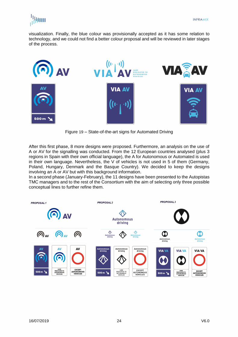
Figure 18 – State-of-Art signs for Automated Driving In a first phase of the design process (December-January) the proposals have been refined by AAE together with the designers (Tandem). The first proposals are shown in the followed figures. Only the first design of the figure 19 was accepted, while the other two were too similar to icons used in many other contexts. We insisted to the designer that traffic signs are usually abstract figures, sometimes letters, and most importantly should not be similar to other icons used in other contexts. Furthermore, an important requirement was its visualization on VMSs, and thus the design should be projected in a 64x64 matrix of pixels to guarantee their correct
16/07/2019 24 V6.0
visualization. Finally, the blue colour was provisionally accepted as it has some relation to technology, and we could not find a better colour proposal and will be reviewed in later stages of the process.
Figure 19 – State-of-the-art signs for Automated Driving
After this first phase, 8 more designs were proposed. Furthermore, an analysis on the use of A or AV for the signalling was conducted. From the 12 European countries analysed (plus 3 regions in Spain with their own official language), the A for Autonomous or Automated is used in their own language. Nevertheless, the V of vehicles is not used in 5 of them (Germany, Poland, Hungary, Denmark and the Basque Country). We decided to keep the designs involving an A or AV but with this background information. In a second phase (January-February), the 11 designs have been presented to the Autopistas TMC managers and to the rest of the Consortium with the aim of selecting only three possible conceptual lines to further refine them.
16/07/2019 25 V6.0
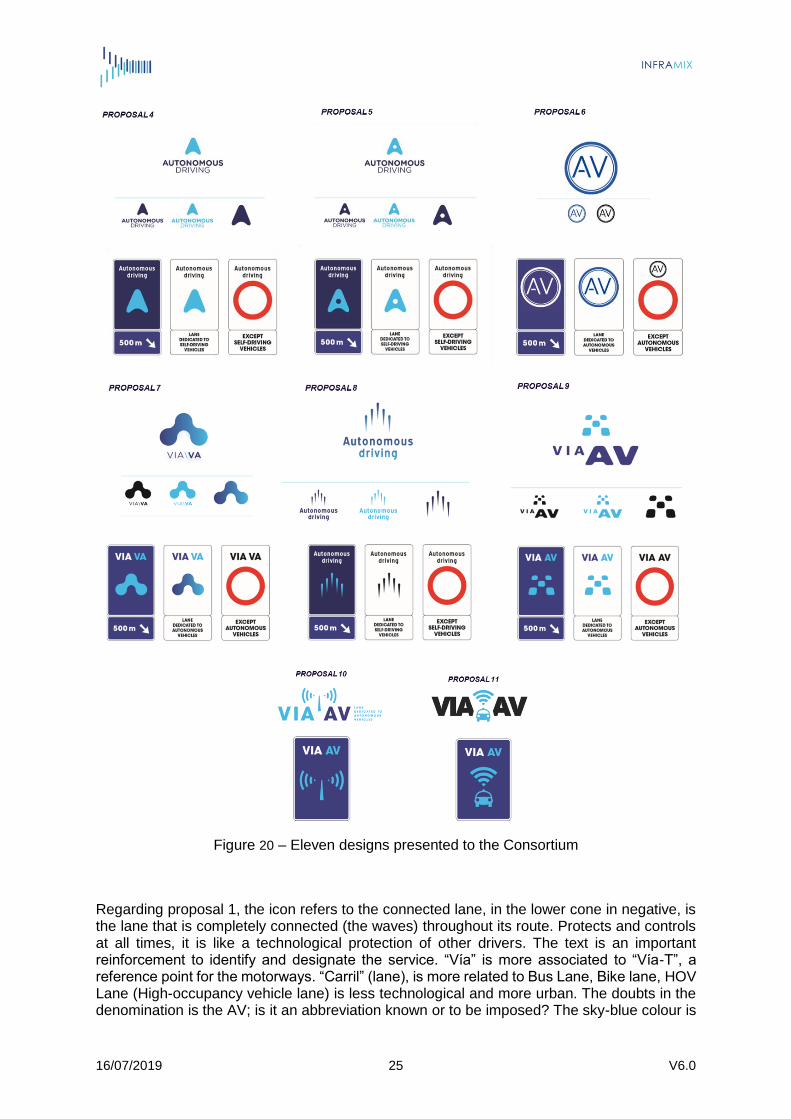
Figure 20 – Eleven designs presented to the Consortium
Regarding proposal 1, the icon refers to the connected lane, in the lower cone in negative, is the lane that is completely connected (the waves) throughout its route. Protects and controls at all times, it is like a technological protection of other drivers. The text is an important reinforcement to identify and designate the service. “Vía” is more associated to “Vía-T”, a reference point for the motorways. “Carril” (lane), is more related to Bus Lane, Bike lane, HOV Lane (High-occupancy vehicle lane) is less technological and more urban. The doubts in the denomination is the AV; is it an abbreviation known or to be imposed? The sky-blue colour is
16/07/2019 26 V6.0
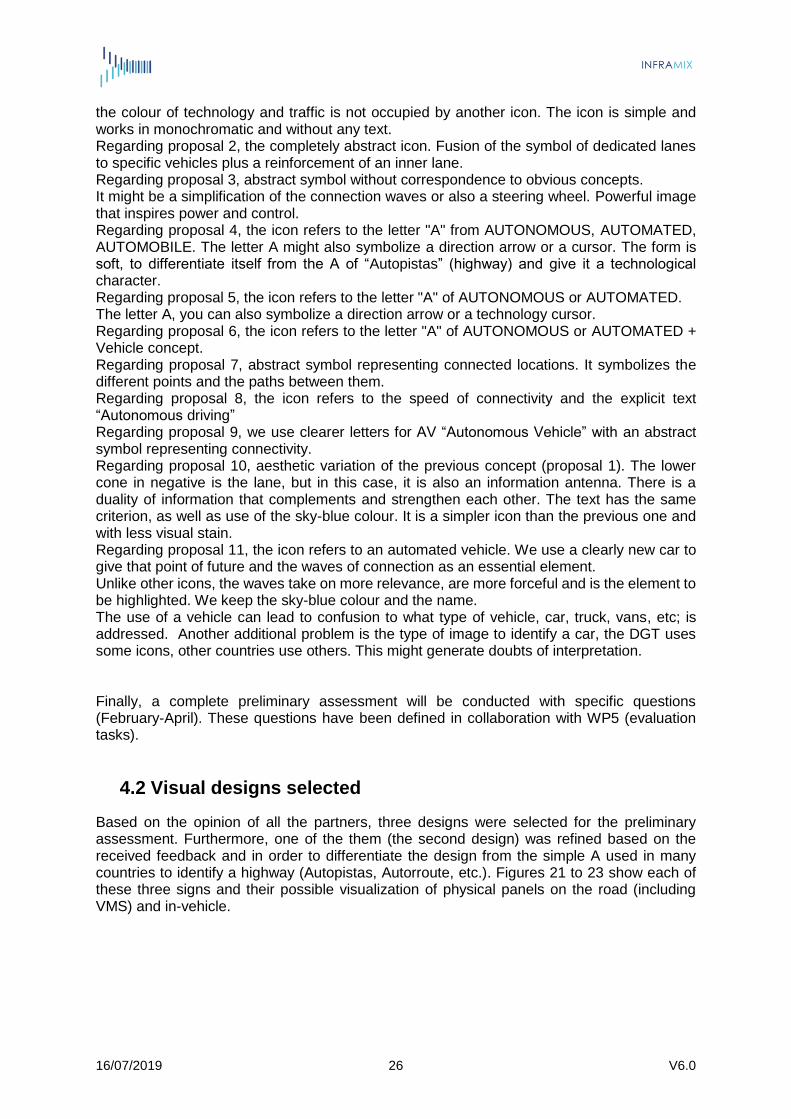
the colour of technology and traffic is not occupied by another icon. The icon is simple and works in monochromatic and without any text. Regarding proposal 2, the completely abstract icon. Fusion of the symbol of dedicated lanes to specific vehicles plus a reinforcement of an inner lane. Regarding proposal 3, abstract symbol without correspondence to obvious concepts. It might be a simplification of the connection waves or also a steering wheel. Powerful image that inspires power and control. Regarding proposal 4, the icon refers to the letter "A" from AUTONOMOUS, AUTOMATED, AUTOMOBILE. The letter A might also symbolize a direction arrow or a cursor. The form is soft, to differentiate itself from the A of “Autopistas” (highway) and give it a technological character. Regarding proposal 5, the icon refers to the letter "A" of AUTONOMOUS or AUTOMATED. The letter A, you can also symbolize a direction arrow or a technology cursor. Regarding proposal 6, the icon refers to the letter "A" of AUTONOMOUS or AUTOMATED + Vehicle concept. Regarding proposal 7, abstract symbol representing connected locations. It symbolizes the different points and the paths between them. Regarding proposal 8, the icon refers to the speed of connectivity and the explicit text “Autonomous driving” Regarding proposal 9, we use clearer letters for AV “Autonomous Vehicle” with an abstract symbol representing connectivity. Regarding proposal 10, aesthetic variation of the previous concept (proposal 1). The lower cone in negative is the lane, but in this case, it is also an information antenna. There is a duality of information that complements and strengthen each other. The text has the same criterion, as well as use of the sky-blue colour. It is a simpler icon than the previous one and with less visual stain. Regarding proposal 11, the icon refers to an automated vehicle. We use a clearly new car to give that point of future and the waves of connection as an essential element. Unlike other icons, the waves take on more relevance, are more forceful and is the element to be highlighted. We keep the sky-blue colour and the name. The use of a vehicle can lead to confusion to what type of vehicle, car, truck, vans, etc; is addressed. Another additional problem is the type of image to identify a car, the DGT uses some icons, other countries use others. This might generate doubts of interpretation. Finally, a complete preliminary assessment will be conducted with specific questions (February-April). These questions have been defined in collaboration with WP5 (evaluation tasks).
4.2 Visual designs selected
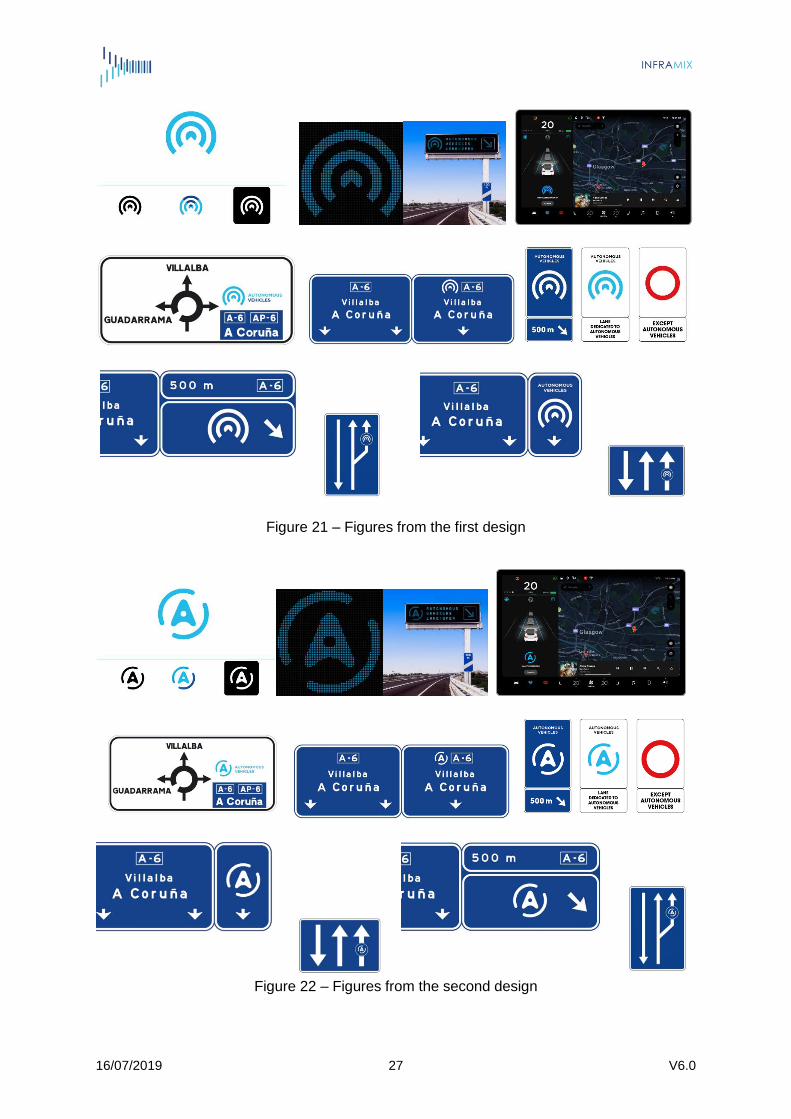
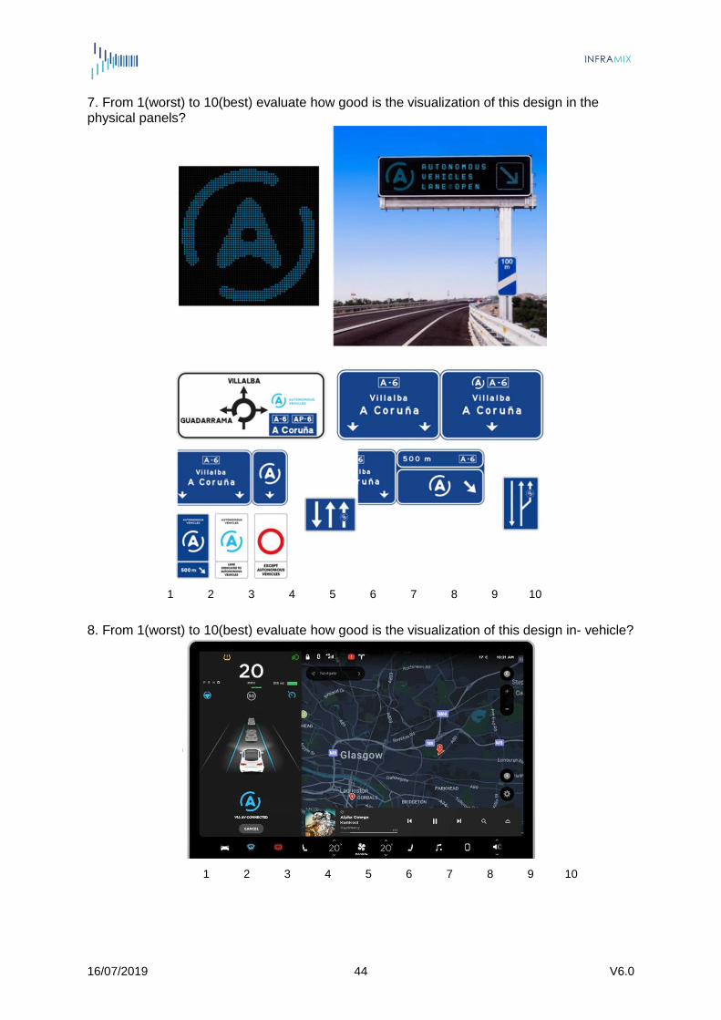
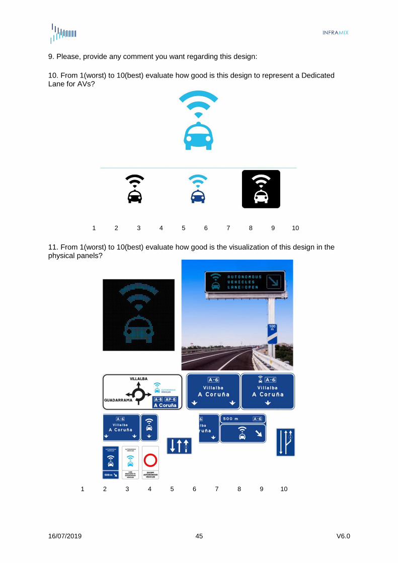
Based on the opinion of all the partners, three designs were selected for the preliminary assessment. Furthermore, one of the them (the second design) was refined based on the received feedback and in order to differentiate the design from the simple A used in many countries to identify a highway (Autopistas, Autorroute, etc.). Figures 21 to 23 show each of these three signs and their possible visualization of physical panels on the road (including VMS) and in-vehicle.
16/07/2019 27 V6.0
Figure 21 – Figures from the first design
Figure 22 – Figures from the second design

16/07/2019 28 V6.0
Figure 23 – Figures from the third design
4.3 Preliminary assessment
In order to conduct a preliminary assessment of the previous designs and with the objective of selecting just one of them for the user appreciation evaluation of WP5, we have created a Survey in Google drive with the questions rating the designs, and their visualization in on-road panels and VMSs, and in an in-vehicle app. The survey was available on https://goo.gl/forms/uQDPN4DvNVr4h7ee2 and copied in Annex II. For the first week, we share it only to Road Operators and Road Authorities as the most relevant stakeholders for this decision. The list included EU ITS Platform and ASECAP members among others. Afterwards, we shared to the rest of Stakeholders identified by the project as final users including (technology providers, drivers associations, research institutions, OEMs, etc. A complete list of the contacted institutions is shown in Table 11.

16/07/2019 29 V6.0
Table 11 – List of contacted institutions
Road Operators / Road Authorities
Others
DGT 3M FEHRL RACC
SCT ACCIÓ Globalvia La Salle
Ferrovial /Cintra AIMSUN GMV RADAR
EU ITS Platform AIPCR HAVELSAN SEAT
ASECAP members Alquimia i2cat SENSEFIELDS
ASFINAG CEDR IDIADA TM2.0
Autopistas CoEXist INDRA TransAID CTAG ITS España UNIZAR ERF KAPSCH UPC ERTRAC LACROIX
ETSC MAVEN
Eurecat Mosaic Factor
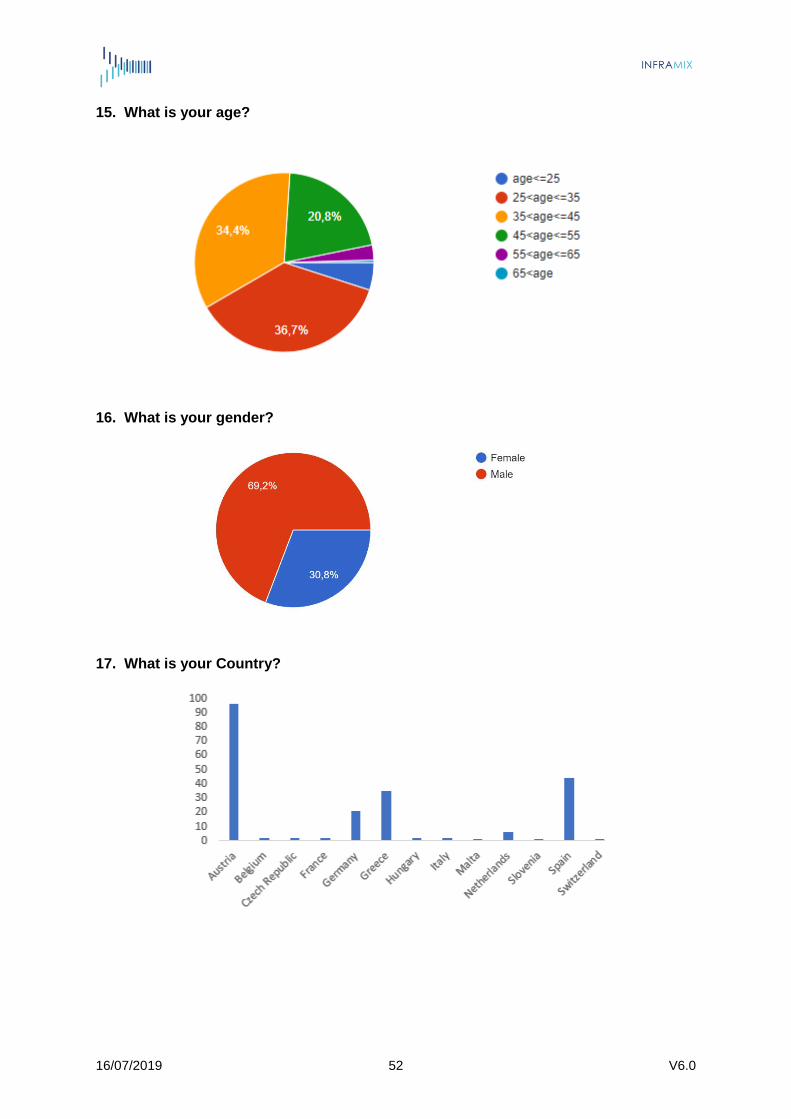
The results from the survey were collected between March 7th and April 12th, 5 weeks. 225 people from 13 European countries participated in the survey.
Figure 24 – Participation by gender
Figure 25 – Participation by age
16/07/2019 30 V6.0
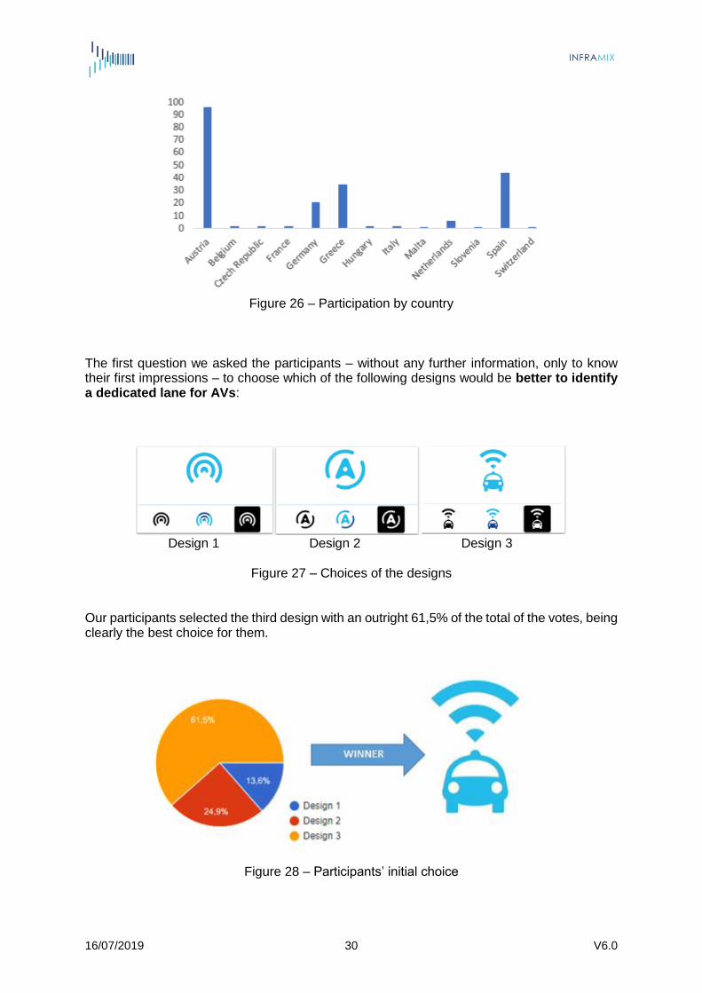
Figure 26 – Participation by country
The first question we asked the participants – without any further information, only to know their first impressions – to choose which of the following designs would be better to identify a dedicated lane for AVs:
Design 1 Design 2 Design 3
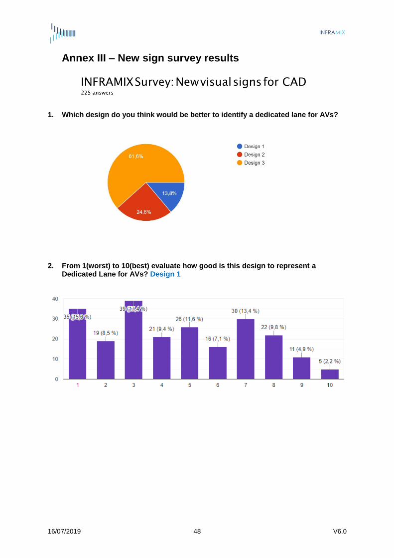
Figure 27 – Choices of the designs Our participants selected the third design with an outright 61,5% of the total of the votes, being clearly the best choice for them.
Figure 28 – Participants’ initial choice
16/07/2019 31 V6.0
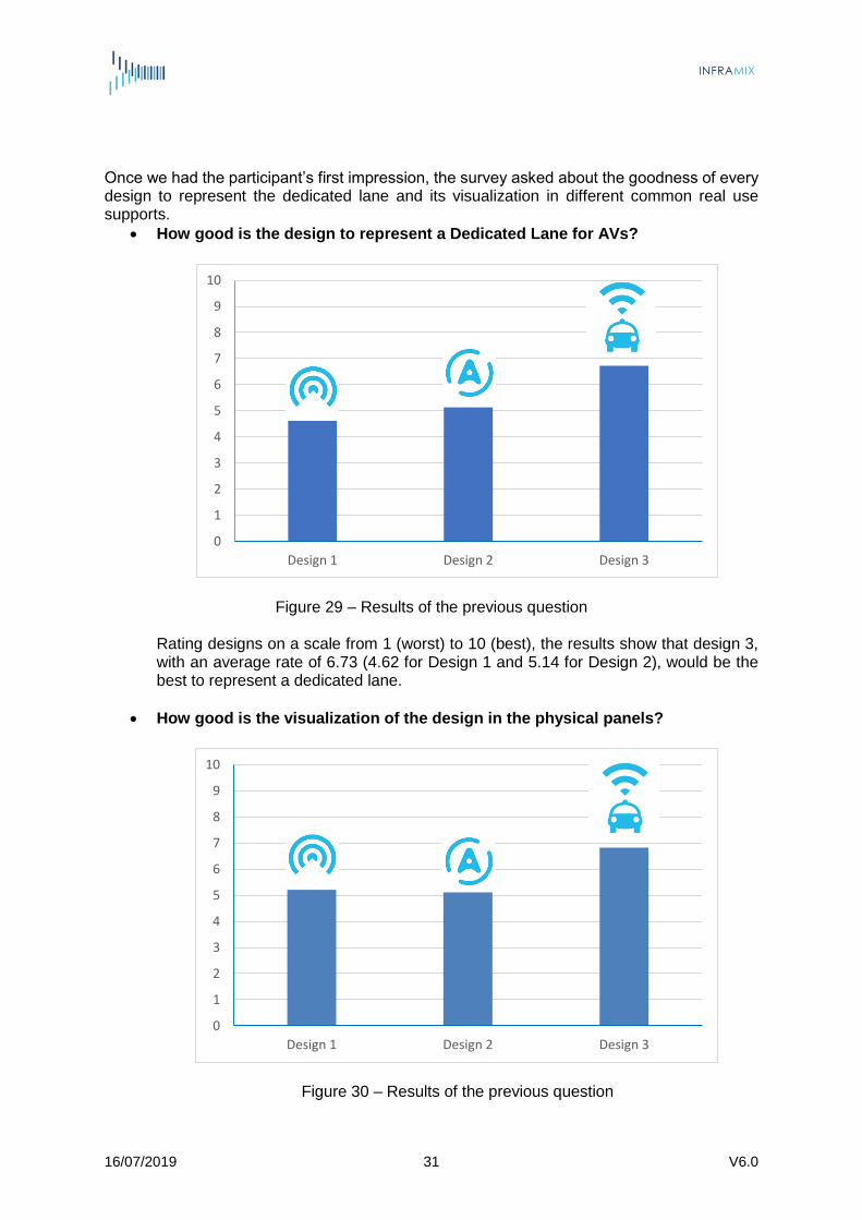
Once we had the participant’s first impression, the survey asked about the goodness of every design to represent the dedicated lane and its visualization in different common real use supports.
How good is the design to represent a Dedicated Lane for AVs?
Figure 29 – Results of the previous question
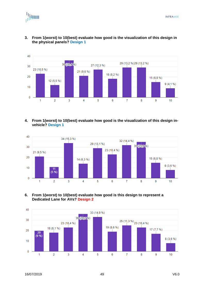
Rating designs on a scale from 1 (worst) to 10 (best), the results show that design 3, with an average rate of 6.73 (4.62 for Design 1 and 5.14 for Design 2), would be the best to represent a dedicated lane.
How good is the visualization of the design in the physical panels?
Figure 30 – Results of the previous question
0
1
2
3
4
5
6
7
8
9
10
Design 1 Design 2 Design 3
0
1
2
3
4
5
6
7
8
9
10
Design 1 Design 2 Design 3

16/07/2019 32 V6.0
Rating designs on a scale from 1 (worst) to 10 (best), the results show that design 3, with an average rate of 6.83 (5.21 for Design 1 and 5.11 for Design 2), has the best visualization on physical panels. We can observe that Design 1, although chosen as the worst option to identify a dedicated lane, is slightly more effective in the physical panels than Design 2.
How good is the visualization of the design in-vehicle?
Figure 31 – Results of the previous question Rating designs on a scale from 1 (worst) to 10 (best), the results show that design 3, with an average rate of 6.67 (5.42 for Design 1 and 5.55 for Design 2), has the best visualization also in in-vehicle displays. Like in physical panels, Design 1 is also preferred to Design 2, but for a minimum difference.
Finally, as a last question, we asked again which design would be better to identify a dedicated lane for AVs. The purpose was to evaluate if after answering the whole survey and seeing all the proposals in different concepts, our participants had changed their minds.
Figure 32 – Participants’ final choice
0
1
2
3
4
5
6
7
8
9
10
Design 1 Design 2 Design 3
16/07/2019 33 V6.0
The results show no representative difference between the first and the last question. Just 8 participants changed their favourite option; basically, moving from Designs 2 and 3 to Design 1. Considering the comments that participants left in the survey, we can identify what are some reasons of their decisions. About Design 1 the comments reflect the idea that it is too similar to the commonly used Wi-Fi symbols. Comments on Design 2 point to confusion; the “A” symbol it is not clearly related to automated and could have many different meanings. With Design 3 there are two big concepts: in one hand could be confused with an emergency vehicle, like an ambulance or a police car; and in the other hand could be very easy to visualize a connected vehicle rather than an automated vehicle. When we analyse the results by gender, age or country, likewise in general results, Design 3 is equally the favourite option in every group. In both genders and representative nationalities, more than half of the votes went to the third design. Age groups and their perception of the new technology and iconography don’t seem to influence the results either. In every age group more than 58% of the participants chose Design 3 as the best option to identify a dedicated lane for AVs. Only when we focus on Road Operators and Road Authorities’ participants the results show a little difference. In this group, although Design 3 is also the favourite of the participants, it doesn’t reach the half of the votes (47.6%) and Design 1 comes close to it (38.1%).
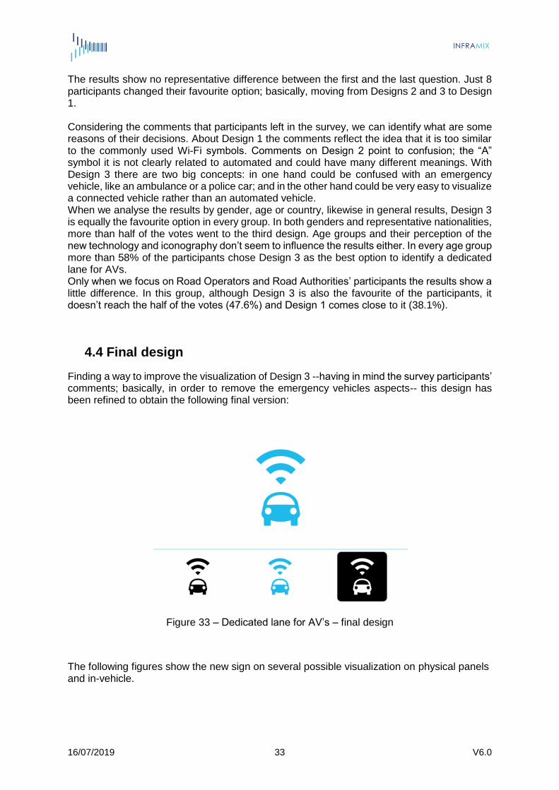
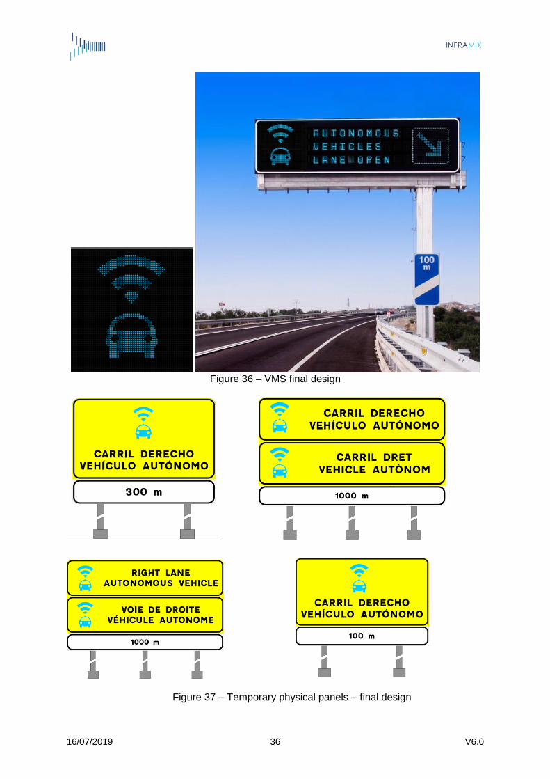
4.4 Final design
Finding a way to improve the visualization of Design 3 --having in mind the survey participants’ comments; basically, in order to remove the emergency vehicles aspects-- this design has been refined to obtain the following final version:
Figure 33 – Dedicated lane for AV’s – final design
The following figures show the new sign on several possible visualization on physical panels and in-vehicle.

16/07/2019 34 V6.0
Figure 34 – Physical panels at highway entries, final design
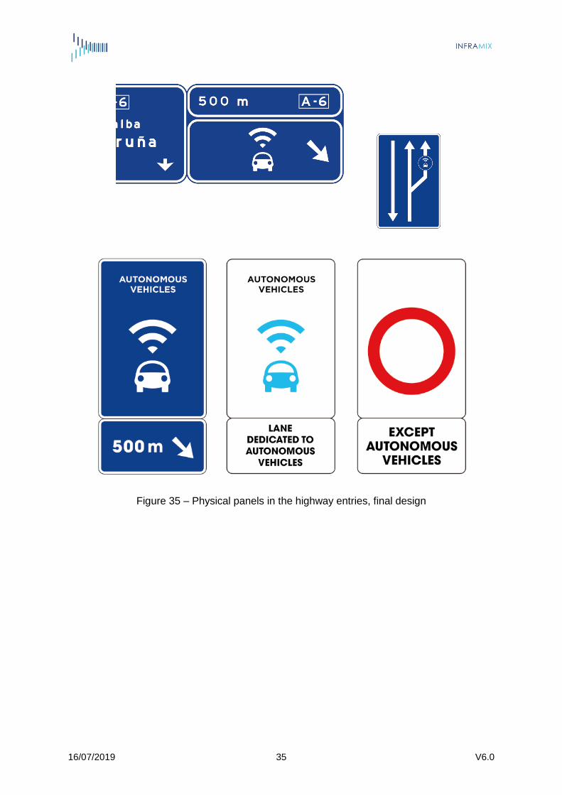
16/07/2019 35 V6.0
Figure 35 – Physical panels in the highway entries, final design
16/07/2019 36 V6.0
Figure 36 – VMS final design
Figure 37 – Temporary physical panels – final design

16/07/2019 37 V6.0
Figure 38 – New sign on asphalt and gantries VMS, final design
Figure 39 – New sign in vehicle, final design
16/07/2019 38 V6.0
5. Conclusions
As a general idea, in “hybrid” roads –with the coexistence of conventional and automated vehicles– in order to ensure safety and efficient traffic flows, the visual signs addressed to the vehicles should be more focused on conventional and connected vehicles rather than automated. For AVs all the information would be provided digitally, whereas for the other group of vehicles visual information is critical as is the main source of information for the driver to make a correct decision. After a complete analysis of the whole set of signs that take part in every scenario and their related use cases, the outcome is that only one new visual sign is needed: the dedicated lane for AVs. In the rest of situation where a sign is required, this could be provided through an already existing sign: physical via VMS or digital via I2V messages. The simulation tools will determinate the minimal distance between segments in a dedicated lane in order to inform to the conventional and connected vehicles about the assignment state of the lane. This distance would define the optimal number of signs to install. On account of the impact of a new traffic sign, main efforts of T3.5 have been targeted to its creation process. Firstly, the requirements of the project, the relevant regulations, and the technical specifications of VMS have been collected and an analysis of the State-of-the-Art on traffic visual signage was completed. Then, in order to create an effective new sign, a four-phase design process has been conducted:
i) 11 initial proposals of designs were presented to the Autopistas TMC managers and to the rest of the Consortium,
ii) 3 designs were selected for the preliminary assessment,
iii) Road Operators and Road Authorities and the stakeholders identified by the project voted on a survey to choose the best design,
iv) Final refining having in mind the participants’ comments from the survey. This new visual sign will be tested in real physical road signage and in-vehicle visualizations in the forthcoming WP4’s demonstrators. A complete evaluation on user appreciation of the outcomes of this task will be done in T5.2.
16/07/2019 39 V6.0
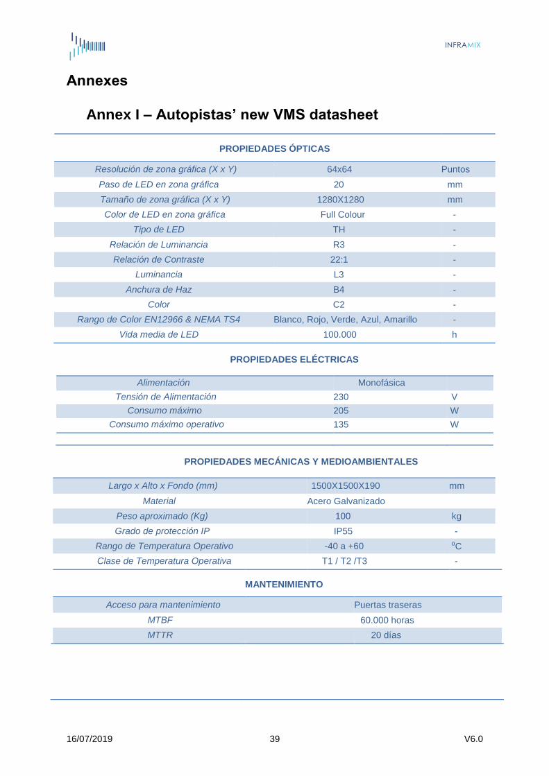
Annexes Annex I – Autopistas’ new VMS datasheet
PROPIEDADES ÓPTICAS
Resolución de zona gráfica (X x Y) 64x64 Puntos
Paso de LED en zona gráfica 20 mm
Tamaño de zona gráfica (X x Y) 1280X1280 mm
Color de LED en zona gráfica Full Colour -
Tipo de LED TH -
Relación de Luminancia R3 -
Relación de Contraste 22:1 -
Luminancia L3 -
Anchura de Haz B4 -
Color C2 -
Rango de Color EN12966 & NEMA TS4 Blanco, Rojo, Verde, Azul, Amarillo -
Vida media de LED 100.000 h
PROPIEDADES ELÉCTRICAS
Alimentación Monofásica
Tensión de Alimentación 230 V
Consumo máximo 205 W
Consumo máximo operativo 135 W
PROPIEDADES MECÁNICAS Y MEDIOAMBIENTALES
Largo x Alto x Fondo (mm) 1500X1500X190 mm
Material Acero Galvanizado
Peso aproximado (Kg) 100 kg
Grado de protección IP IP55 -
Rango de Temperatura Operativo -40 a +60 ⁰C
Clase de Temperatura Operativa T1 / T2 /T3 -
MANTENIMIENTO
Acceso para mantenimiento Puertas traseras
MTBF 60.000 horas
MTTR 20 días

16/07/2019 40 V6.0
COMUNICACIONES
Comunicación Serie RS-232/RS-485 o Ethernet
Protocolo NTCIP, DGT, MODBUS o Web Server
Mantenimiento RS-232
Actualización de Firmware Protocolo & USB
Paquete de comunicación Modem (CONNECT)
Bluetooth, Wi-Fi, 3G o 4G

16/07/2019 41 V6.0
Annex II – New sign preliminary assessment survey
INFRAMIX Survey: New visual signs for CAD
INFRAMIX is an EU-funded project preparing the road infrastructure to support the
transition period and the coexistence of conventional and automated vehicles. Its main
target is to design, upgrade, adapt and test both physical and digital elements of the
road infrastructure, ensuring an uninterrupted, predictable, safe and efficient traffic. To
meet this high level objective INFRAMIX is working on different technologies. It starts
with the use of mature simulation tools adapted to the peculiarities of automated vehicles
and develops new methods for traffic flow modelling, to study the traffic-level influence
of different levels of automated vehicles in different penetration rates. It also implements
relevant traffic estimation and control algorithms dynamically adapted to the current
situation. Then it goes up to propose minimum, targeted and affordable adaptations on
elements of the road infrastructure, either physical or digital or a combination of them.
This work includes ways of informing all types of vehicles about the control commands
issued by the road operator and the proposal of new kind of visual and digital signals for
the needs of mixed scenarios. The outcomes will be assessed via simulation and in real
stretches of advanced highways. Key aspects considered throughout the project will be
to ensure that the proposed adaptations will not jeopardize safety, quality of service,
efficiency and will be appreciated by the users.
In this context, we ask you please to reply the following questions regarding three
possible designs for the new required visual signs. In this case, the main objective is to
inform about the existence of a dedicated lane for Connected Automated Vehicles in a
highway.
Thank you very much!!
INFRAMIX Team
1. Which design do you think would be better to identify a dedicated lane for AVs?
Design 1 Design 2 Design 3

16/07/2019 42 V6.0
2. From 1(worst) to 10(best) evaluate how good is this design to represent a Dedicated Lane for AVs?
1 2 3 4 5 6 7 8 9 10
3. From 1(worst) to 10(best) evaluate how good is the visualization of this design in the physical panels?
1 2 3 4 5 6 7 8 9 10
16/07/2019 43 V6.0
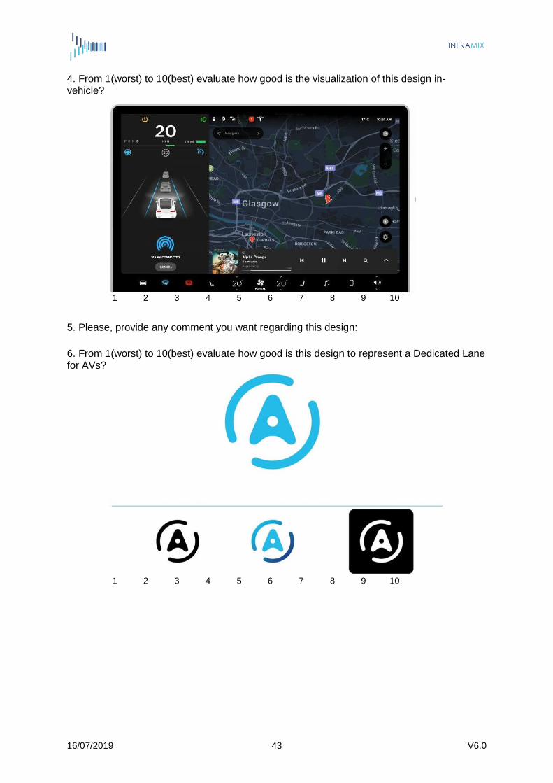
4. From 1(worst) to 10(best) evaluate how good is the visualization of this design in- vehicle?
1 2 3 4 5 6 7 8 9 10
5. Please, provide any comment you want regarding this design: 6. From 1(worst) to 10(best) evaluate how good is this design to represent a Dedicated Lane for AVs?
1 2 3 4 5 6 7 8 9 10
16/07/2019 44 V6.0
7. From 1(worst) to 10(best) evaluate how good is the visualization of this design in the physical panels?
1 2 3 4 5 6 7 8 9 10
8. From 1(worst) to 10(best) evaluate how good is the visualization of this design in- vehicle?
1 2 3 4 5 6 7 8 9 10
16/07/2019 45 V6.0
9. Please, provide any comment you want regarding this design: 10. From 1(worst) to 10(best) evaluate how good is this design to represent a Dedicated Lane for AVs?
1 2 3 4 5 6 7 8 9 10
11. From 1(worst) to 10(best) evaluate how good is the visualization of this design in the physical panels?
1 2 3 4 5 6 7 8 9 10
16/07/2019 46 V6.0
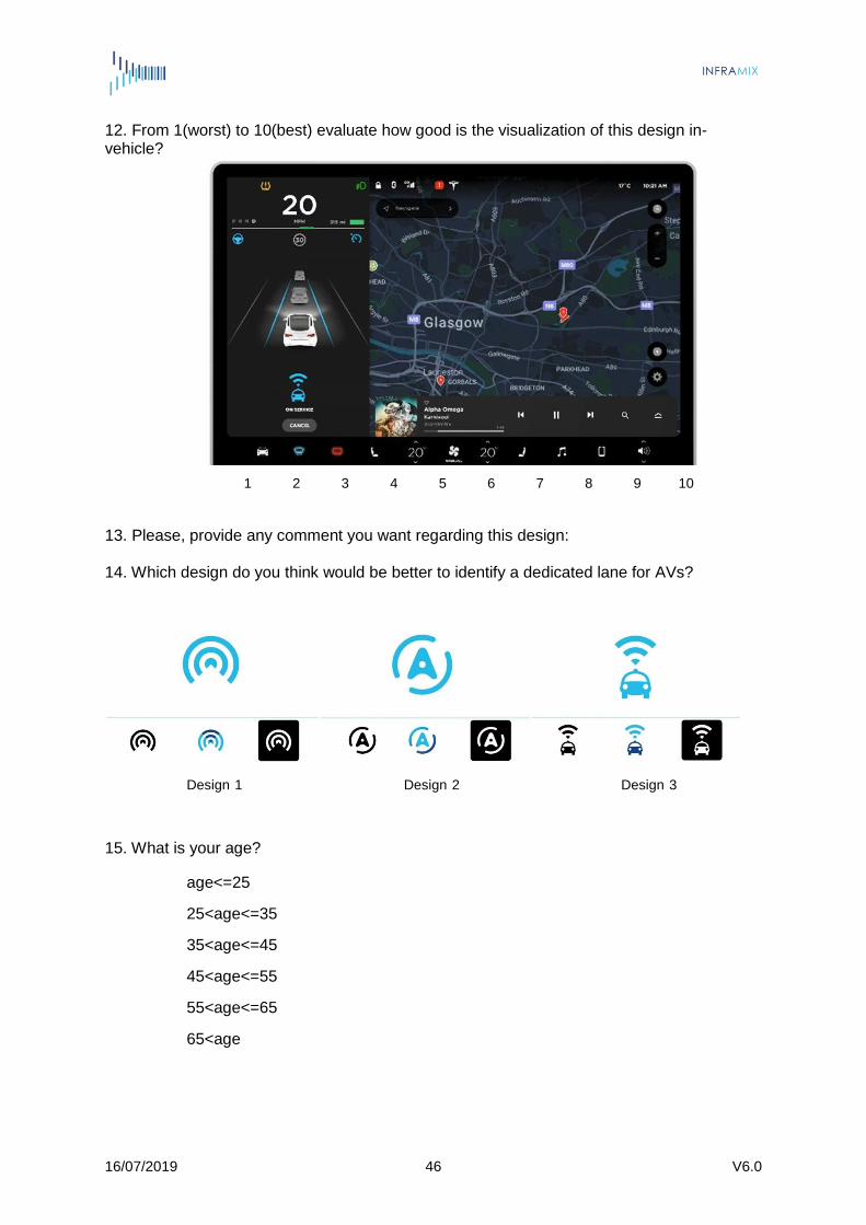
12. From 1(worst) to 10(best) evaluate how good is the visualization of this design in- vehicle?
1 2 3 4 5 6 7 8 9 10
13. Please, provide any comment you want regarding this design:
14. Which design do you think would be better to identify a dedicated lane for AVs?
Design 1 Design 2 Design 3
15. What is your age?
age<=25
25<age<=35
35<age<=45
45<age<=55
55<age<=65
65<age

16/07/2019 47 V6.0
16. What is your gender?
Female
Male
17. What is your country?
16/07/2019 48 V6.0
Annex III – New sign survey results
INFRAMIX Survey: New visual signs for CAD
225 answers
1. Which design do you think would be better to identify a dedicated lane for AVs?
2. From 1(worst) to 10(best) evaluate how good is this design to represent a
Dedicated Lane for AVs? Design 1
16/07/2019 49 V6.0
3. From 1(worst) to 10(best) evaluate how good is the visualization of this design in
the physical panels? Design 1
4. From 1(worst) to 10(best) evaluate how good is the visualization of this design in-
vehicle? Design 1
6. From 1(worst) to 10(best) evaluate how good is this design to represent a
Dedicated Lane for AVs? Design 2

16/07/2019 50 V6.0
7. From 1(worst) to 10(best) evaluate how good is the visualization of this design in
the physical panels? Design 2
8. From 1(worst) to 10(best) evaluate how good is the visualization of this design in-
vehicle? Design 2
10. From 1(worst) to 10(best) evaluate how good is this design to represent a Dedicated Lane for AVs? Design 3

16/07/2019 51 V6.0
11. From 1(worst) to 10(best) evaluate how good is the visualization of this design in the physical panels? Design 3
12. From 1(worst) to 10(best) evaluate how good is the visualization of this design in-
vehicle? Design 3
14. Which design do you think would be better to identify a dedicated lane for AVs?
16/07/2019 52 V6.0
15. What is your age?
16. What is your gender?
17. What is your Country?
16/07/2019 53 V6.0
References
[1] CEN TC226 WG 12: Road interaction - ADAS / Autonomous vehicles
[2] A. Carreras, X. Daura, J. Erhart, S.Ruehrup. Road infrastructure support levels for automated driving, 25th ITS World Congress, Copenhagen, Denmark, 17-21 September 2018
[3] ERTRAC Connected and Automated Driving Roadmap 2019 https://www.ertrac.org/uploads/documentsearch/id57/ERTRAC-CAD-Roadmap-2019.pdf
[4] SAE level clearance. ECo-AT Release 4.0 System Specification request http://eco-at.info/Specification_request.html
[5] EU 2008. Directive 2008/96/EC of the European Parliament and of the Council of 19 November 2008 on road infrastructure safety management. Official Journal of the European Union 29.11.20118, L 319/59-67
[6] Variable Message Signs Harmonisation, PRINCIPLES OF VMS MESSAGES DESIGN, ITS Platform. VMS-DG01 | VERSION 02-02-00 | DECEMBER 2015 https://portal.its-platform.eu/index.php?q=filedepot_download/1729/5384
[7] EU EIP 2016. Facilitating Automated Driving and ITS, EU EIP A4.2 Workshop in Madrid, 21 – 22 September 2016
[8] Real Decreto 1428/2003, de 21 de noviembre, por el que se aprueba el Reglamento General de Circulación para la aplicación y desarrollo del texto articulado de la Ley sobre tráfico, circulación de vehículos a motor y seguridad vial, aprobado por el Real Decreto Legislativo 339/1990, de 2 de marzo https://www.boe.es/buscar/act.php?id=BOE-A-2003-23514
[9] Normas y señales reguladoras de la circulación (Ed. 2015) http://www.dgt.es/Galerias/seguridad-vial/formacion-vial/cursos-para-profesores-y-directores-de-autoescuelas/XVIII-Curso-de-Profesores/Normas-y-seniales.pdf
[10]
Norma de carreteras 8.1-I.C
https://www.fomento.gob.es/recursos_mfom/norma81ic.pdf
16/07/2019 54 V6.0
[11] Norma de carreteras 8.2-I.C
https://www.fomento.gob.es/recursos_mfom/1120100.pdf
[12] Norma de carreteras 8.3-I.C
https://www.fomento.gob.es/recursos_mfom/1130100.pdf
[13] Real Decreto 2822/1998, de 23 de diciembre, por el que se aprueba el Reglamento General de Vehículos. (BOE nº 22, de 26 de enero de 1999; corrección de errores en BOE nº 38, de 13 de febrero de 1999) http://www.dgt.es/Galerias/seguridad-vial/normativa-legislacion/reglamento-trafico/reglamento_trafico126.pdf
[14] Instrucción DGT 15/V-113 Autorización de pruebas o ensayos de investigación realizados con vehículos de conducción automatizada en vías abiertas al tráfico en general http://www.dgt.es/Galerias/seguridad-vial/normativa-legislacion/otras- normas/modificaciones/15.V-113-Vehiculos-Conduccion-automatizada.pdf