d3.2 report on design of tcms distributed simulation ... · d3.2 – report on design of tcms...
TRANSCRIPT

D3.2
Report on Design of TCMS Distributed Simulation Framework Concept
Project number: 730830 Project acronym: Safe4RAIL
Project title: Safe4RAIL: SAFE architecture for Robust distributed Application Integration in roLling stock
Start date of the project: 1st October, 2016
Duration: 24 months
Programme: H2020-S2RJU-OC-2016-01-2
Deliverable type: Report
Deliverable reference number: ICT-730830 / D3.2 / FINAL | 1.0
Work package WP 3
Due date: Jul 2017 – M10
Actual submission date: 31th July, 2017
Responsible organisation: Ikerlan SCL
Editor: Pedro Rodríguez
Dissemination level: Public
Revision: FINAL | 1.0
Abstract:
Proposed a design of a Communication Emulator which is part of a Simulation Framework to validate and test TCMS components. This Simulation Framework will support SIL and HIL connected via heterogeneous networks.
Keywords: Simulation Framework, Communication Emulator, TCMS testing
This project has received funding from the Shift2Rail Joint Undertaking under grant agreement No 730830. This Joint Undertaking receives support from the European Union’s Horizon 2020 research and innovation programme.
D3.2 – Report on Design of TCMS Distributed Simulation Framework Concept
Editor
Pedro Rodríguez (IKL)
Contributors (ordered according to beneficiary numbers)
Rafael Priego, Cristina Cruces, Iñaki Val (IKL)
Tobias Pieper, Maryam Pahlevan (SIE)
Tomáš Tichý, Richard Pecl (UNI)
Moritz Pogrzeba (TÜV)
Youlian Kirov (IAV)
Mario Münzer (TEC)
Disclaimer
The information in this document is provided “as is”, and no guarantee or warranty is given that the information is fit for any particular purpose. The content of this document reflects only the author`s view – the European Commission is not responsible for any use that may be made of the information it contains. The users use the information at their sole risk and liability.
D3.2 – Report on Design of TCMS Distributed Simulation Framework Concept
Executive Summary
In order to advance the development of the railway industry, the integration and testing of new railway components are crucial. This process can be radically improved by using a distributed simulation and validation framework. This framework is the objective for two European research projects: CONNECTA and Safe4RAIL.
The proposed distributed simulation and validation framework will support Software- and Hardware-In-The-Loop (SIL/HIL) testing, as well as the secure coupling of simulators and physical systems via heterogeneous communication networks. This framework is a network-centric simulator that allows co-simulating End Device (ED) models with network models to gain insight into the functionality, timing, reliability and safety of the Train Control and Monitoring System (TCMS) from a network point of view. The framework ensures the validations of TCMS by means of automation and fault injection tests. This framework will be composed by a Simulation Framework (SF), in charge of electromechanical and functional simulation, and a Communication Emulator (CE), in charge of providing communication among all the different devices in the TCMS. The aforementioned projects will be in charge of developing the whole system: CONNECTA focuses on the SF and Safe4RAIL on the CE.
This deliverable focuses on the description of the different use cases that defines the correct interaction of the CE with its users and test tools. On the other hand, the deliverable defines the correct behaviours and interactions of the actors, entities and subsystems that compose the CE. This definition is based on a series of architecture models, scope models and dynamic models. Finally, a series of sequence diagrams are presented which define the communication and interactions between the different subsystems for each of the use cases.
D3.2 – Report on Design of TCMS Distributed Simulation Framework Concept
Contents
Executive Summary ................................. ................................................................ 3
Contents .......................................... .......................................................................... 4
List of Figures ................................... ........................................................................ 7
List of Tables .................................... ........................................................................ 9
Chapter 1 Introduction ...................................... ................................................. 10
Chapter 2 Requirements ...................................... .............................................. 11
Chapter 3 Use Cases ......................................... ................................................. 12
Use case 1: Configuration ....................................................................................... 13
3.1.1 Scenario 1: Configuration when only one CETS attempts to be the CETSmaster .....13
3.1.2 Scenario 2: Configuration when a second CETS attempts to be the CETSmaster ....14
3.1.3 Scenario 3: Configuration with an incorrect configuration file ................................14
Use Case 2: Reconfiguration .................................................................................. 14
3.1.4 Scenario 1: Reconfiguration with a correct reconfiguration file ..............................14
3.1.5 Scenario 2: Reconfiguration with an incorrect reconfiguration file..........................15
Use Case 3: SFTS commands (Start, pause, step, resume, stop, fault_injection, monitoring etc.) ....................................................................................................... 15
3.1.6 Scenario 1: Transmission of SFTS commands ......................................................15
Use Case 4: Ethernet interaction ............................................................................ 15
3.1.7 Scenario 1: Transmission of Ethernet frame .........................................................16
Use Case 5: I/O interaction ..................................................................................... 16
3.1.8 Scenario 1: transmission of the I/O value ..............................................................16
Use Case 6: Monitoring/measurements start .......................................................... 16
3.1.9 Scenario 1: CETSmaster starts the monitoring/measurements .................................16
3.1.10 Scenario 2: CETSslave starts the monitoring/measurements ...............................17
Use Case 7: Monitoring/measurement stop ............................................................ 17
3.1.11 Scenario 1: CETSmaster stops the monitoring/measurements .............................17
3.1.12 Scenario 2: CETSslave stops the monitoring/measurements ...............................17
Use Case 8: Configuration data request ................................................................. 18
3.1.13 Scenario 1: Request the configuration data from the CESTc .............................18
Use Case 9: Simulation stop ................................................................................... 18
3.1.14 Scenario 1: Stop the simulation from the CETSmaster ..........................................18
Use Case 10: Fault injection start ........................................................................... 18
3.1.15 Scenario 1: CETSmaster starts the fault injection .................................................18

D3.2 – Report on Design of TCMS Distributed Simulation Framework Concept
3.1.16 Scenario 2: CETSslave starts the fault injection ...................................................19
Use Case 11: Fault injection stop ........................................................................... 19
3.1.17 Scenario 1: CETSmaster stops injecting a fault .....................................................19
3.1.18 Scenario 2: CETSslave stops injecting a fault ......................................................19
Chapter 4 Scope Model ....................................... ............................................... 20
4.1 Actors ............................................................................................................. 20
4.2 Entities ........................................................................................................... 21
4.2.1 Co-simulation entity...............................................................................................21
4.2.1.1 The High Level Architecture ..........................................................................22
4.2.1.1.1 Overview about the HLA ........................................................................................ 22
4.2.1.1.2 Time management in the HLA ................................................................................ 22
4.2.1.1.3 Co-simulation subsystem sequence diagrams ....................................................... 23
4.2.1.1.4 Time synchronization for SIL and HIL simulation ................................................... 26
4.2.1.1.5 The HLA FOM ........................................................................................................ 28
4.2.1.2 The Functional Mockup Interface ..................................................................30
4.2.2 Network simulator .................................................................................................31
4.2.3 Communication Security .......................................................................................31
4.2.3.1 Establishing Secure Tunnel ...........................................................................32
Chapter 5 Architecture model ................................ ........................................... 34
5.1 Interfaces ....................................................................................................... 38
5.1.1 Interface SFTS – CETS ........................................................................................38
5.1.2 Interface SFTS – CESB ..........................................................................................39
5.1.3 Interface Real ED – CESB ......................................................................................39
5.1.4 Interface SF (Sim. Tool) – CESB ............................................................................40
5.2 Architectural requirements validation ............................................................. 40
Chapter 6 Dynamic model ..................................... ............................................. 44
Chapter 7 Subsystem model ................................... .......................................... 46
7.1 User Interface Subsystem .............................................................................. 46
7.2 Configurator Subsystem (Central) .................................................................. 48
7.2.1 Configuration file ...................................................................................................51
7.3 Configurator Subsystem (Master/Slave) ........................................................ 59
7.4 Configuration Subsystem ............................................................................... 62
7.5 Monitoring Subsystem (Simulation Bridge) .................................................... 63
7.6 Monitoring Subsystem (Central)..................................................................... 64
7.7 Monitoring Subsystem (Master/Slave) ........................................................... 65
7.8 Communication Subsystem (Central) ............................................................ 66
7.9 Communication Subsystem (Master/Slave, Simulation Bridge) ..................... 69
D3.2 – Report on Design of TCMS Distributed Simulation Framework Concept
7.10 Wrapper Subsystem ................................................................................... 72
7.10.1 Wrapper Subsystem for Simulation Tools with I/O as FMI variables ..................72
7.10.2 Wrapper Subsystem for Simulation Tools with real I/O ......................................73
7.10.3 Wrapper Subsystem for HIL ..............................................................................74
7.10.4 Wrapper Subsystem for HIL with I/O .................................................................75
7.11 Delay Manager Subsystem ........................................................................ 76
7.11.1 Delay-Management concept .............................................................................76
7.11.2 Delay-Management Model ................................................................................77
7.11.3 State-Estimation Functionality ...........................................................................79
7.12 Fault injection Subsystem .......................................................................... 81
7.13 Co-Simulation Subsystem .......................................................................... 82
7.14 Network Simulator Subsystem ................................................................... 88
Chapter 8 Instantiation of the system ....................... ........................................ 93
Chapter 9 Summary and conclusions ........................... .................................... 96
Chapter 10 List of Abbreviations ............................. ........................................ 97
Chapter 11 Bibliography ...................................... ............................................. 99
Chapter 12 Appendix 1: Sequence diagrams ..................... .......................... 101

D3.2 – Report on Design of TCMS Distributed Simulation Framework Concept
List of Figures
Figure 1. Scope model of the co-simulation framework. .......................................................20
Figure 2. HLA synchronization points ...................................................................................24
Figure 3. HLA synchronize behaviour ...................................................................................25
Figure 4. HLA time management ..........................................................................................26
Figure 5: Synchronization steps: a) scheduled tasks of end device, b) HLA services and synchronization steps ...................................................................................................27
Figure 6. Establishing Secure Tunnel between RTI and Federate ........................................33
Figure 7. Architecture model of the co-simulation framework. ...............................................35
Figure 8. Architecture model of Central PC ..........................................................................36
Figure 9. Architecture model of Communication Emulator Toolset........................................37
Figure 10. Architecture model of Communication’s Emulator Simulation Bridge ...................38
Figure 11. LC replaced by RC using CE ...............................................................................40
Figure 12. CE handles multiple LCN .....................................................................................41
Figure 13. CETS handles multiple CE ..................................................................................41
Figure 14. Only one CETS per CE........................................................................................42
Figure 15. SIM handles multiple EDS ...................................................................................42
Figure 16. EDS distributable .................................................................................................42
Figure 17. SFTS and SIM connection ...................................................................................42
Figure 18. CE integrated into SIM ........................................................................................42
Figure 19. Dynamic model of the Communication Emulator (CE). ........................................45
Figure 20. Dynamic model of the User Interface Subsystem. ...............................................47
Figure 21. Dynamic model of the Configurator (Central) Subsystem. ...................................50
Figure 22. Dynamic model of the Configurator (Master/Slave) Subsystem. ..........................61
Figure 23. Dynamic model of the Configuration Subsystem. ................................................63
Figure 24. Dynamic model of the Monitoring (Simulation Bridge) Subsystem. ......................64
Figure 25. Dynamic model of the Monitoring (Central) Subsystem. ......................................65
Figure 26. Dynamic model of the Monitoring (Master/Slave) Subsystem. .............................66
Figure 27. Dynamic model of the Communication (Central) Subsystem. ..............................68
Figure 28. Dynamic model of the Communication (Master/Slave, Simulation Bridge) Subsystem. ...................................................................................................................71
Figure 29. Dynamic model of the Wrapper Subsystem for Simulation Tools. ........................73
Figure 30. Dynamic model of the Wrapper Subsystem for Simulation Tools with I/O . ..........74
Figure 31. Dynamic model of the Wrapper Subsystem for HIL. ............................................75
Figure 32. Dynamic model of the Wrapper Subsystem for HIL with I/O. ...............................76
Figure 33. Dynamic model of the Delay Manager Subsystem ...............................................79

D3.2 – Report on Design of TCMS Distributed Simulation Framework Concept
Figure 34. Dynamic model of the State-Emulator Functionality .............................................81
Figure 35. Dynamic model of the Fault injection Subsystem .................................................82
Figure 36. Dynamic model of the Co-simulation Subsystem. ................................................83
Figure 37. Dynamic model of the Connect and init state. ......................................................84
Figure 38. Dynamic model of the Registration state .............................................................85
Figure 39. Dynamic model of the Configured and running state. ..........................................86
Figure 40. Dynamic model of the Reconfiguration state. .......................................................87
Figure 41. Dynamic model of the Disconnect state. ..............................................................88
Figure 42 Dynamic model of the Network Simulator Subsystem. ..........................................90
Figure 43 Dynamic model of the Switch machine state. ........................................................92
Figure 44. Sample scenario for instantiation of the system ...................................................93
Figure 45. Sample instantiation of the system. .....................................................................94
Figure 46. Sample instantiation of the system with simulated network. .................................95
Figure 47. Use case 1. Scenario 1...................................................................................... 102
Figure 48. Use case 1. Scenario 2...................................................................................... 103
Figure 49. Use case 1. Scenario 3...................................................................................... 104
Figure 50. Use case 2. Scenario 1...................................................................................... 105
Figure 51. Use case 2. Scenario 2...................................................................................... 106
Figure 52. Use case 3. Scenario 1...................................................................................... 107
Figure 53. Use case 4. Scenario 1...................................................................................... 108
Figure 54. Use case 5. Scenario 1...................................................................................... 109
Figure 55. Use case 6. Scenario 1...................................................................................... 110
Figure 56. Use case 6. Scenario 2...................................................................................... 111
Figure 57. Use case 7. Scenario 1...................................................................................... 112
Figure 58. Use case 7. Scenario 2...................................................................................... 113
Figure 59. Use case 8. Scenario 1...................................................................................... 114
Figure 60. Use case 9. Scenario 1...................................................................................... 115
Figure 61. Use case 10. Scenario 1. ................................................................................... 116
Figure 62. Use case 10. Scenario 2. ................................................................................... 117
Figure 63. Use case 11. Scenario 1. ................................................................................... 118
Figure 64. Use case 11. Scenario 2. ................................................................................... 119
D3.2 – Report on Design of TCMS Distributed Simulation Framework Concept
List of Tables
Table 1: FMI variables for communication between CE and ED ...........................................31
Table 2. Commands of the interface SFTS – CETS. ............................................................39
Table 3: Interface for the State-Estimation functionality ........................................................80
Table 4: List of Abbreviations ...............................................................................................98

D3.2 – Report on Design of TCMS Distributed Simulation Framework Concept
SAFE4RAIL D3.2 Page 10 of 119
Chapter 1 Introduction
In order to test the new technologies and architectural concepts presented by the Safe4RAIL project, a distributed simulation and validation framework is necessary. This framework is composed of a Simulation Framework (SF) in charge of electromechanical and functional simulation, and a Communication Emulator (CE) in charge of providing communication among all the different devices in the Train Control and Monitoring System (TCMS). In this document, a high level design for the CE is presented.
The main objective is to develop a CE that provides a safe communication among the different devices in the TCMS network. This CE allows simulated and physical devices (End Device (ED), Vehicle Control Unit (VCU), Human Machine Interface (HMI), among others) to be connected via heterogeneous networks.
This deliverable focuses on the description of the entities, actors, subsystems and functionalities of the CE. The structure of this deliverable is organized as follows:
• Chapter 2 gives an overview of the different functional and non-functional requirements the CE needs to provide in order to allow the validation and simulation of a TCMS.
• Chapter 3 is composed of a series of Use Cases that define and guide the interactions the different users or actors will experience when using the CE.
• Chapter 4 provides a depiction of the different actors and entities that composes the TCMS, focusing on the part of the software that is under design and its connection to other components of the system.
• Chapter 5 presents the architecture model that represents the different elements, interfaces and information used by the CE to ensure the communication, monitoring and management of the system.
• Chapter 6 focuses on the behaviour of the CE and how it reacts to stimulus coming from the user or other systems.
• Chapter 7 deals with the description of the sub-systems that composes the different elements of the CE.
• Chapter 8 presents a sample instantiation of the designed CE for a sample TCMS network.
• Chapter 9 provides a summary of the document.

D3.2 – Report on Design of TCMS Distributed Simulation Framework Concept
SAFE4RAIL D3.2 Page 11 of 119
Chapter 2 Requirements
In order to ensure the correct behaviour and interactions of the CE, a series of functional and non-functional requirements have been proposed. These requirements have been collected as part of Safe4RAIL’s deliverable D3.6 [1]. This deliverable distributes the requirements into different groups that deal with specific characteristics of the CE:
• Distributed Co-Simulation Requirements
• Software-In-The-Loop Requirements
• Hardware-In-The-Loop Requirements
• Test Operation and Test Automation Requirements
• Applicability Requirements
• Configuration Requirements
• Security Requirements
Additional architectural requirements have been provided by the CONNECTA project regarding the connection and interaction between the ED and the simulation framework. These requirements are collected in [2].

D3.2 – Report on Design of TCMS Distributed Simulation Framework Concept
SAFE4RAIL D3.2 Page 12 of 119
Chapter 3 Use Cases
The Use Case model is a catalogue of repeatable interactions or steps that a user (or “actor” in the Unified Modelling Language (UML)) experiences when using the system. A Use Case includes one or more “scenarios”, and each scenario describes the interactions that go on between the actor and the system. Results and exceptions that occur from the user’s perspective are documented.
First of all, some parts of the system which will be referenced in the use case models are going to be detailed and explained:
• Simulation Framework (SF): The SF is the system which is in charge of simulating the functional and electromechanical devices. This system is designed by CONNECTA.
• Simulation Framework Tool Set (SFTS): The SFTS is the system which is in charge of controlling the SF, and it is also designed by CONNECTA.
• Communication Emulator (CE): The CE is the system which connects all the devices of the simulation, as well as the Tool Set in charge of commanding them. It is composed by a CE controller (CEc) and one or several Simulation Bridges (CESB); both of them are explained below:
o Communication Emulator Controller (CEc): The CEc coordinates the simulation; it coordinates how the different CESB exchange information.
o Communication Emulator, Simulation Bridge (CESB): The CESB is in charge of connecting the different devices in the network to build the TCMS network through a heterogeneous network.
• Communication Emulator Tool Set (CETS): The CETS is the system which is in charge of configuring, monitoring and controlling the CE. It is composed by a master CETS (CETSmaster), a central CETS (CETSc), and a slave CETS (CETSslave), which are explained bellow:
o Communication Emulator Tool Set, Master (CETSmaster): The CETSmaster will be responsible for configuring and starting the CE; it will send a file to the CEc including all the configuration data. It receives commands for configuration and monitoring from an external user and sends it to the CEc.
o Central Communication Emulator Tool Set (CETSc): The CETSc will coordinate the configuration, control and monitoring of the CETS. It receives the commands for configuration and monitoring from the CETSmaster, and routes them to their destination, the different CESB in the simulation.
o Communication Emulator Tool Set, Slave (CETSslave): A CETSslave allows configuring, controlling and monitoring some CESB locally. A CETSslave should tell the CETSc which CESB is going to control, and the CETSc coordinates this to not allow more than one CETS (master or slave) to control the same CESB.
• Network simulator: a simulator to simulate the switches of the TCMS when no real switches are present in the test.
The list of Use Cases which have been defined for the CE is:
• Configuration
• Reconfiguration
• SFTS command (Start, pause, step, resume, stop, fault-injection, monitoring, etc.)

D3.2 – Report on Design of TCMS Distributed Simulation Framework Concept
SAFE4RAIL D3.2 Page 13 of 119
• Ethernet interaction
• I/O interaction
• Monitoring/measurement start
• Monitoring/measurement stop
• Configuration file request
• Stop
• Fault injection start
• Fault injection stop
All of them, and their different scenarios, are explained below.
Use case 1: Configuration
Goal: The CETSmaster must open the Virtual Private Network (VPN) to secure the communication with the CETSc and send the configuration file. The necessary information is related to:
- Identification number and IP address of each CESB. - Identification number and IP address of each CETSslave in the simulation. - Identification number of all the CESB controlled by each CETSslave. - Configuration of the co-simulation tool. - Establish if the network devices (switches) should be simulated or real network devices
are connected to the SF. If they should be simulated, configure them (get the info to inaugurate the network, etc.).
3.1.1 Scenario 1: Configuration when only one CETS attempts to be the CETS master
Precondition: the CEc is running the VPN server and the PCs containing the CESBs and CETSslaves of the simulation are switched on and have their corresponding programs executing. No CETSmaster has been established and the configuration file is correct.
Steps:
1. The CETS receives a configuration command and the configuration file from a SFTS or a User.
2. A CETS opens a VPN connection and a socket with the CETSc. This CETS is established as the CETSmaster.
3. The CETSmaster sends the configuration file to the CETSc. 4. The CETSc analyses the configuration file, configures the CEC and the network
simulator, and starts them. 5. The CETSc opens a VPN and a socket with each and every CESB and CETSslave
(specified by the configuration file) in the network. 6. The CETSc asks all the CETSslaves which CESBs they are going to control. 7. Each CETSslave sends to the CETSc which CESBs they are going to control. 8. The CETSc tells to the CETSmaster which CESBs are not controlled by a CETSslave (they
will be controlled by the CETSmaster), and any possible problem regarding the CETSslaves.
9. Each CETSslave connects with the CESBs they must control. 10. All the CETSslaves send to the CESBs the configuration file and they are configured. 11. CESBs initialize, connect and do the co-simulation registration.

D3.2 – Report on Design of TCMS Distributed Simulation Framework Concept
SAFE4RAIL D3.2 Page 14 of 119
12. Each and every CESB confirms to the CETSc that everything works correctly. 13. The CETSc goes to a started state and reports it to the CETSmaster. 14. END.
3.1.2 Scenario 2: Configuration when a second CETS attempts to be the CETS master
Precondition: the CEc is running, the VPN server and the PCs containing the CESBs and CETSslaves of the simulation are switched on and have their corresponding programs executing. Another CETSmaster has been already established.
Steps:
1. The CETS receives a configuration command and the configuration file from a SFTS or a User.
2. A CETS opens a VPN connection and a socket with the CETSc, and sends the configuration file.
3. The CETSc reports that other CETS has been established as the CETSmaster. 4. END.
3.1.3 Scenario 3: Configuration with an incorrect configuration file
Precondition: the CEC is running the VPN server and the PCs containing the CESBs and CETSslaves of the simulation are switched on and have their corresponding programs executing. No CETSmaster has been established but the configuration file is not correct.
Steps:
1. The CETS receives a configuration command and the configuration file from a SFTS or a User.
2. A CETS opens a VPN connection and a socket with the CETSc, and sends the configuration file. This CETS is established as the CETSmaster.
3. The CETSmaster sends the configuration file to the CETSc. 4. The CETSc analyses the configuration file and detects some mistakes in it. 5. The CETSc reports to the CETSmaster that the file is not correct. 6. END.
Use Case 2: Reconfiguration
Goal: reconfigure the system, maintaining the same network structure as in the previous test.
3.1.4 Scenario 1: Reconfiguration with a correct reconfiguration file
Precondition: the system has been configured and the reconfiguration file is correct.
Steps:
1. The CETS receives a reconfigure command and the configuration file from a SFTS or a User.

D3.2 – Report on Design of TCMS Distributed Simulation Framework Concept
SAFE4RAIL D3.2 Page 15 of 119
2. The CETSmaster sends the reconfigure command and the reconfiguration file to the CETSc.
3. The CETSc analyses the reconfiguration file. 4. The reconfiguration data is sent to the CESBs and the CETSslaves. 5. The CETSc asks all the CETSslaves which CESBs they are going to control. 6. Each CETSslave sends to the CETSc which CESBs they are going to control. 7. The CETSc tells to the CETSmaster which CESBs are not controlled by a specific CETSslave
(they will be controlled by the CETSmaster), and any possible problem regarding the CETSslaves.
8. Each CETSslave connects to the CESBs it must control. 9. CESBs do the registration. 10. CESBs confirm everything works correctly through the socket. 11. The CETSc reports to the CETSmaster that the reconfiguration has been done. 12. END.
3.1.5 Scenario 2: Reconfiguration with an incorrect reconfiguration file
Precondition: the system is running and the reconfiguration file is not correct.
Steps:
1. The CETS receives a reconfigure command and the configuration file from a SFTS or a User.
2. The CETSmaster sends the reconfigure command and the reconfiguration file to the CETSc.
3. The CETSc analyses the reconfiguration file and detects it is not correct. 4. The CETSc reports to the CETSmaster that the file is not correct.
Use Case 3: SFTS commands (Start, pause, step, resu me, stop, fault_injection, monitoring etc.)
Goal: the SFTS sends a command which the CE shall pass on to the EDs.
3.1.6 Scenario 1: Transmission of SFTS commands
Precondition: the CE has been configured.
Steps:
1. The command is sent from the SFTS. 2. The CESB takes the command and translates it to a co-simulation interaction. 3. The interaction is sent to the CESBs of the destination EDs. 4. The interaction is translated into the original command and it is sent to the EDs. 5. END.
Use Case 4: Ethernet interaction
Goal: an ED sends an Ethernet frame which the CE shall pass on to the destination EDs.
D3.2 – Report on Design of TCMS Distributed Simulation Framework Concept
SAFE4RAIL D3.2 Page 16 of 119
3.1.7 Scenario 1: Transmission of the Ethernet fram e
Precondition: the CE has been configured.
Steps:
1. The ED sends the Ethernet frame. 2. The CESB takes the Ethernet frame and translates it into a co-simulation interaction. 3. The co-simulation interaction is sent to the CESBs of the destination EDs. 4. The interaction is translated into the original Ethernet frame and it is sent to the
destination EDs. 5. END.
Use Case 5: I/O interaction
Goal: an ED changes the value of its I/O which the CE shall pass on to the destination EDs.
3.1.8 Scenario 1: transmission of the I/O value
Precondition: the CE has been configured and a change has been detected in the I/O.
Steps:
1. The CESB obtains a sample from the I/O and translates it into a co-simulation interaction.
2. The co-simulation interaction is sent to the CESB of the destination ED. 3. The interaction is translated to the I/O. 4. END.
Use Case 6: Monitoring/measurements start
Goal: start the monitoring or measuring of all signals/messages in a CESB.
3.1.9 Scenario 1: CETS master starts the monitoring/measurements
Precondition: the CE has been configured and the CETSmaster sends the monitoring_start command indicating the CESB which shall start the monitoring/measurements.
Steps:
1. The CETS receives a monitoring_start command from a SFTS or a User. 2. The CETSmaster sends the monitoring_start command to the CETSc indicating the CESB
which shall start the monitoring/measurement process. 3. The CETSc sends the command to the desired CESB. 4. The CESB starts monitoring or measuring data. The data is sent to the CETSmaster if the
CESB was told to monitor it, or it is saved in a file and sent to the CETSmaster at the end of the simulation if it was told to measuring it. The data and files are sent from the CESB to the CETSmaster by routing them through the CETSc.
D3.2 – Report on Design of TCMS Distributed Simulation Framework Concept
SAFE4RAIL D3.2 Page 17 of 119
5. END.
3.1.10 Scenario 2: CETS slave starts the monitoring/measurements
Precondition: the CE, the CETSmaster and all the CETSslave have been properly configured, and one CETSslave sends the monitoring_start to a CESB.
Steps:
1. The CETS receives a monitoring_start command from a SFTS or a User. 2. The CETSslave sends the monitoring_start command to the CESB. 3. The CESB starts monitoring or measuring data. The data is sent to the CETS if the CESB
was told to monitor it, or it is saved in a file and sent to the CETSslave at the end of the simulation if it was told to measuring it.
4. END.
Use Case 7: Monitoring/measurement stop
Goal: stop the monitoring or measuring in a CESB.
3.1.11 Scenario 1: CETS master stops the monitoring/measurements
Precondition: the CE has been configured, the CETSmaster sends the monitoring_stop command indicating the CESB which shall stop the monitoring/measurements and this CESB is monitoring/measuring.
Steps:
1. The CETS receives a monitoring_stop command from a SFTS or a User. 2. The CETSmaster sends the monitoring_stop command to the CETSc indicating the CESB
which shall stop the monitoring/measurement process. 3. The CETSc sends the command to the desired CESB. 4. The CESB stops monitoring or measuring data. 5. END.
3.1.12 Scenario 2: CETS slave stops the monitoring/measurements
Precondition: the CE has been configured, the CETSslave sends the monitoring_stop to the CESB which shall stop the monitoring/measurements and this CESB is monitoring/measuring.
Steps:
1. The CETS receives a monitoring_stop command from a SFTS or a User. 2. The CETSslave sends the monitoring_stop command to the CESB. 3. The CESB stops monitoring or measuring data. 4. END.

D3.2 – Report on Design of TCMS Distributed Simulation Framework Concept
SAFE4RAIL D3.2 Page 18 of 119
Use Case 8: Configuration data request
Goal: request for the configuration file and receive it.
3.1.13 Scenario 1: Request the configuration data f rom the CETSc
Precondition: the CE has been configured and CETSmaster or CETSslave sends the config_request command to the CETSc.
Steps:
1. The CETS receives a config_request command from a SFTS or a User. 2. The CETSmaster or the CETSslave sends the config_request command to the CETSc. 3. The CETSc sends the configuration file to the CETSmaster or the CETSslave. 4. END.
Use Case 9: Simulation stop
Goal: stop the simulation.
3.1.14 Scenario 1: Stop the simulation from the CET Smaster
Precondition: the CE has been configured and it is running.
Steps:
1. The CETS receives a stop command from a SFTS or a User. 2. The CETSmaster sends the stop command to the CETSc. 3. The CETSc sends the stop command to every CESBs in the simulation. 4. Every CESB disconnects the co-simulation execution. 5. Every CESB which has saved measured data into a file sends it to the CETSslave through
the socket. If the CESB is controlled by the CETSmaster, the data is sent through the CETSc.
6. Every CESB confirms that the stop has been done to the CETSc. 7. The CETSc confirms that the stop has been done to the CETSmaster and all the CETSslave. 8. All sockets are closed. 9. The VPN is closed.
Use Case 10: Fault injection start
Goal: start the introduction of faults into de communication of a CESB. These faults refer to the introduction of a communication delay or message jamming.
3.1.15 Scenario 1: CETS master starts the fault injection
Precondition: the CE has been configured.
Steps:
1. The CETS receives a fault_injection command from a SFTS or a User.

D3.2 – Report on Design of TCMS Distributed Simulation Framework Concept
SAFE4RAIL D3.2 Page 19 of 119
2. The CETSmaster sends the fault_injection command to the CETSc indicating the CESB
which shall start the fault injection process and the fault to be injected. 3. The CETSc sends the command to the desired CESB. 4. The CESB starts introducing the fault into the communication. 5. END.
3.1.16 Scenario 2: CETS slave starts the fault injection
Precondition: the CE has been configured.
Steps:
1. The CETS receives a fault_injection command from a SFTS or a User. 2. The CETSslave sends the fault_injection command to the CESB indicating the fault to be
injected. 3. The CESB starts introducing the fault into the communication. 4. END.
Use Case 11: Fault injection stop
Goal: stop injecting of a specific fault in a CESB.
3.1.17 Scenario 1: CETS master stops injecting a fault
Precondition: the CE has been configured and this CESB is injecting a fault.
Steps:
1. The CETS receives a fault_reset command from a SFTS or a User. 2. The CETSmaster sends the fault_reset command to the CETSc indicating the CESB which
shall stop the fault injection process and the fault to be stopped. 3. The CETSc sends the command to the desired CESB. 4. The CESB stops injecting the fault. 5. END.
3.1.18 Scenario 2: CETS slave stops injecting a fault
Precondition: the CE has been configured and this CESB is injecting a fault.
Steps:
1. The CETS receives a fault_reset command from a SFTS or a User. 2. The CETSslave sends the fault_reset command to the CESB and the fault to be stopped. 3. The CESB stops injecting the fault. 4. END.

D3.2 – Report on Design of TCMS Distributed Simulation Framework Concept
SAFE4RAIL D3.2 Page 20 of 119
Chapter 4 Scope Model
The scope model represents the part of the software which is under design, and its relationship with the rest of the components of the system. The goal of this model is to represent the boundary of the system which has to be designed, being left outside the rest of the components (actors). Usually, the system to be designed uses libraries, which are also represented within the boundary (entities). Therefore, a scope model should define:
• Users (actors) of the system which interact with the system.
• The devices (entities) contained within the system, and libraries which are used by the system.
• The inter-relationship between these devices and the software itself.
• All messaging between the software and the devices.
The scope model of the designed system (the CE) is shown in Figure 1. The part of the software we are going to develop is represented within a rounded square meanwhile the rest of the existing system components are represented with square boxes. As the system emulates the communication between train components, these components are the actors. Furthermore, additional actors such as an external user or the SFTS are considered. All these actors are delved below.
Figure 1. Scope model of the co-simulation framework.
4.1 Actors
Actors are the users of the system, which will have a well-defined role and have useful interactions with the systems. As stated before, in the CE case, the actors are devices which are present in railway networks, such as EDs and the TCMS network. Furthermore, an external
custom Scope Model diagram
System Boundary
System
Co-simulation Entity
Real TCMS
(from Actors)
Internet/LAN
(from Actors)
User
(from Actors)
Simulation Framework Toolset
(from Actors)
Network Simulation Tool
Entity
Real ED, VCU, HMI, I/O Boards
(from Actors)
SW ED, VCU, HMI, I/O Boards
(from Actors)
Communication Security Entity
Ethernet frames
I/O
Calls/Callbacks to thenetwork simulator
Monitorization, Configuration, Simulation commands
Calls/Cal lbacks to thecommunication
security
Ethernet frames
Monitorization, Configuration, Simulation commands I/O
Ethernet frames
Calls/Callbacks to thecosimulation entity
I/O
Ethernet frames
D3.2 – Report on Design of TCMS Distributed Simulation Framework Concept
SAFE4RAIL D3.2 Page 21 of 119
user, the SFTS and the internet or LAN to achieve distributed simulations are also considered. These actors are explained in more details below:
• User: An external user may be capable of connecting to the co-simulation framework to carry out monitoring, configuration tasks or to command the simulation (start/stop the simulation, etc.). The simulation state will be reported to the user.
• Simulation Framework Toolset (SFTS): Framework used to command the functional simulation. The SFTS will carry out monitoring, configuration and simulation commanding tasks. It also receives information about the functional simulation state.
• Real End Device (ED), Vehicle Control Unit (VCU), Human Machine Interface (HMI), I/O Boards: a real ED, VCU, HMI or I/O boards can be connected to the simulation framework for testing purposes. VCU, HMI or I/O boards are parts of the TCMS network. A VCU is required so as to carry out control and monitoring functions in the TCMS, and HMIs and/or I/O boards may be used in order to validate an ED or for training purposes. Finally, any real ED such as doors controller can be evaluated using the CE, it may be connected to the SF using internet or a LAN which allows a remote validation of the device.
• SW ED, VCU, HMI, I/O Boards: the ED under test, the VCU, the HMI or the I/O Board may be implemented in software and executed in a PC which is connected to the CESB using the Ethernet or I/O. In this case, it is possible to command the execution of the software by the SFTS. Some commands such as start and stop may be available in the SFTS.
• Real network devices (switches): real network devices connected to the CE. A real or SW ED will be virtually connected to this network device by using the CE. The ED will be connected to a Consist Switch (CS) of the network according to the IEC 61375-3-4. The standard also allows an ED to be connected to a Train Backbone Node (TBN), but this option is not considered in the design because it is not widely implemented by train builders.
• Internet/LAN: CE may be connected to the simulation framework through the Internet or LAN. This allows testing an ED connected to the same LAN or located in a different place than the CESB.
All these actors exchange information with the designed system by Ethernet frames, which are sent/received using a heterogeneous network such as the Internet or a LAN. Inside these Ethernet frames the data of the different messages of every actor will be encapsulated. For example, test messages will be sent by the SFTS or railway protocols data by EDs.
4.2 Entities
The entities are the libraries which the system should use to carry out their objective. In the CE three entities will be used: a network simulator to simulate the TCMS network in case a real one is not connected to the CE, a co-simulation entity to exchange information between simulators and/or real devices and to synchronize them and a communication security entity to encrypt the information exchanged via the Internet.
4.2.1 Co-simulation entity
There are already several frameworks for co-simulation presented in section 4.4 of deliverable D3.1 [3] which provide mechanisms for synchronization and data exchange over the Internet. However, they are all designed for specific simulation tools without any generic interface or compatibility to existing standards. These are only two of the main disadvantages. In the following, the usage of the High Level Architecture (HLA) and the Functional Mockup Interface

D3.2 – Report on Design of TCMS Distributed Simulation Framework Concept
SAFE4RAIL D3.2 Page 22 of 119
(FMI) are discussed. Both overcome the lacks of adaptability and interoperability of different simulation tools.
4.2.1.1 The High Level Architecture
The HLA standard was initially developed by the U.S. Modeling and Simulation Coordination Office [4] and connects a set of individual components over a network. These components are called federates and may be computer simulations, supporting utilities or interfaces to live partitions [5].
4.2.1.1.1 Overview about the HLA
Designed at a level independent of any languages and platforms, the HLA supports solutions to the most common problems of interoperability. The only requirements are capabilities for the interconnection with other federates by the exchange of data. Otherwise, there are no constraints on what is represented or how [4]. In addition to interoperability, the HLA was designed for the reuse of components. Each federate must document its object model using a standard Object Model Template (OMT) which is intended for information sharing to facilitate the reuse [5].
Data exchange in the HLA is realized based on services. They are implemented in the Runtime Infrastructure (RTI) as the central component which acts as a distributed operating system. The services are categorized into different types such as data exchange, federation management, declaration management as well as time management and they can be accessed using a standardized interface [4]. Federation management includes the creation/deletion of federation executions and enables the federates to join or resign from them. Furthermore, the execution can be paused, check-pointed or resumed. Declaration management provides services to publish object attribute updates or interactions between federates and to subscribe to them. The advancement of the logical time and its relationship to wall-clock time during the execution is coordinated by the time management services. These categories are only a subset of those defined in the standard. However, the remaining services are not considered in this project [6].
Since the HLA was introduced, several implementations of free and commercial RTI implementations have been developed. Examples for commercial implementations are the MÄK High Performance RTI or the Pitch pRTI. Although they provide promising capabilities, they were not considered due to license costs unless there are no other opportunities. Free and available alternatives are CERTI, the Portico Project or OpenRTI. On the one hand, the selected RTI has to provide all required services. On the other hand, discontinued implementations shall be avoided and it is beneficial if the source code can be adapted during the development of the TCMS distributed co-simulation framework. Since the OpenRTI is still in development, the source code is freely available and it provides all required services such as the categories described above, it was selected for the proof-of-concept implementation of the framework.
4.2.1.1.2 Time management in the HLA
In the HLA, time is modelled as points along the HLA time axis. Each joined federate can associate itself with those points which then delineate the federate's logical time. Furthermore, it can assign time-stamps to its activities represented as messages. During its execution, the federate can advance along the time axis to a logical time which is greater than or equal to its current logical time. The progress can either be unconstrained or constrained by other federates and it is controlled by the time management services of the HLA [7]. These services interact with the HLA's object management services to provide a causally correct and ordered information delivery.
Messages in the HLA represent interactions between federates or attribute updates of objects in the simulations. They can include a time-stamp which is used to order the messages. To send a time-stamped message in a federation-wide time-stamped order (TSO), a federate
D3.2 – Report on Design of TCMS Distributed Simulation Framework Concept
SAFE4RAIL D3.2 Page 23 of 119
must be time-regulating while it has to be time-constrained to receive the message. The default state of a federate upon joining the federation execution is neither time-regulating nor time-constrained and the federate must call the EnableTimeRegulation and EnableTimeConstrained services first. If coordination with other federates is not required, the newly joined federate can remain in the default state.
A time-regulating federate shall specify a non-negative value called lookahead when it attempts to become time-regulating. The lookahead is a guarantee from the federate to the federation that it will not send any TSO message during the time interval between the current logical time and this time plus the lookahead. Hence, the RTI only grants time advances to a logical time which does not violate this constrain
To provide a time-stamped ordered message delivery, the RTI must ensure that a time-constrained federate will never receive a TSO message in its past. Hence, a bound called Greatest Available Logical Time (GALT) is placed on those federates. It limits the advance in the logical time to only those times, where it is guaranteed that no TSO message will be sent to the federate. A request beyond the GALT is only granted, if the bound has increased beyond the requested time. The GALT is calculated by the RTI based on the federates' logical times, lookaheads and time advance requests. It increases during the execution when the time-regulating federates advance in time. Since non-constrained federates can always become time-constrained, the GALT is calculated for each federate. In this case, it represents the bound which would be applied when the federate becomes time-constrained.
Each time advance must be requested explicitly using the TimeAdvanceRequest or NextMessageRequest services. While the time advance services are used by time-stepped federates, event-stepped ones use the next message requests. The first type grants time-steps to the requested logical time. In contrast, the second type of services may also grant a step to a logical time before the requested one. This enables the federate to react on external events which are not known locally. By calling one of those services, the time-regulating federate guarantees that it will not send any TSO message until the requested time plus its lookahead. The RTI grants the time advance by responding with the TimeAdvanceGrant callback which takes the granted logical time as parameter. Until the response, the federate is not permitted to advance in time since the grant guarantees that there will be no further message sent to the federate. While the time-regulating federates must advance in time to enable progress in the time-constraint ones, also federates which are not time-regulating can advance in time. However, these advances have no effect on other federates unless the federate becomes time-regulating.
4.2.1.1.3 Co-simulation subsystem sequence diagrams
The following sequence diagrams denote the interactions which are exchanged between the federates and the RTI to realize the following actions: (I) the registration and announcement of synchronization points, (II) the behaviour of the federates if those points are achieved and (III) the interactions related to the time management services of the HLA.
D3.2 – Report on Design of TCMS Distributed Simulation Framework Concept
SAFE4RAIL D3.2 Page 24 of 119
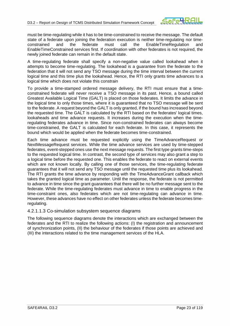
Figure 2. HLA synchronization points
Figure 2 shows the announcement of a synchronization point. While Federate 0 is responsible to register the point, Federate 1 only waits for the announcement. On each federate, a second thread is executed which acts as a callback-handler. The callbacks of the OpenRTI implementation are non-blocking. Hence, the federate has to call the evokeCallback function to check if a callback is available. One possible solution is busy waiting which is not useful in case of HIL simulations since CPU resources are wasted. An alternative is the usage of a second thread. The main thread is blocked and the callback-handler periodically checks the availability of a callback. Between the calls of evokeCallback, this thread is also blocked. If a callback is available, the handler wakes up the main thread which can continue its execution.
In the beginning, Federate 1 has to wait for the announcement of a synchronization point. Hence it passes the control to the callback-handler which is returned as soon as the synchronizationPointAnnounced callback is received.
Federate 0 starts with the function call registerSynchronizationPoint. The call is answered by the RTI using the synchronizationPointRegistered callback as a notification. The announcement follows in the next message and is received by all federates in the synchronization set. This set contains all federates which have to wait for the synchronization point and is not necessarily the complete federation.
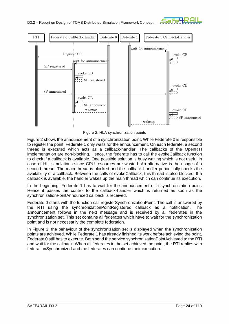
In Figure 3, the behaviour of the synchronization set is displayed when the synchronization points are achieved. While Federate 1 has already finished its work before achieving the point, Federate 0 still has to execute. Both send the service synchronizationPointAchieved to the RTI and wait for the callback. When all federates in the set achieved the point, the RTI replies with federationSynchronized and the federates can continue their execution.
D3.2 – Report on Design of TCMS Distributed Simulation Framework Concept
SAFE4RAIL D3.2 Page 25 of 119
Figure 3. HLA synchronize behaviour
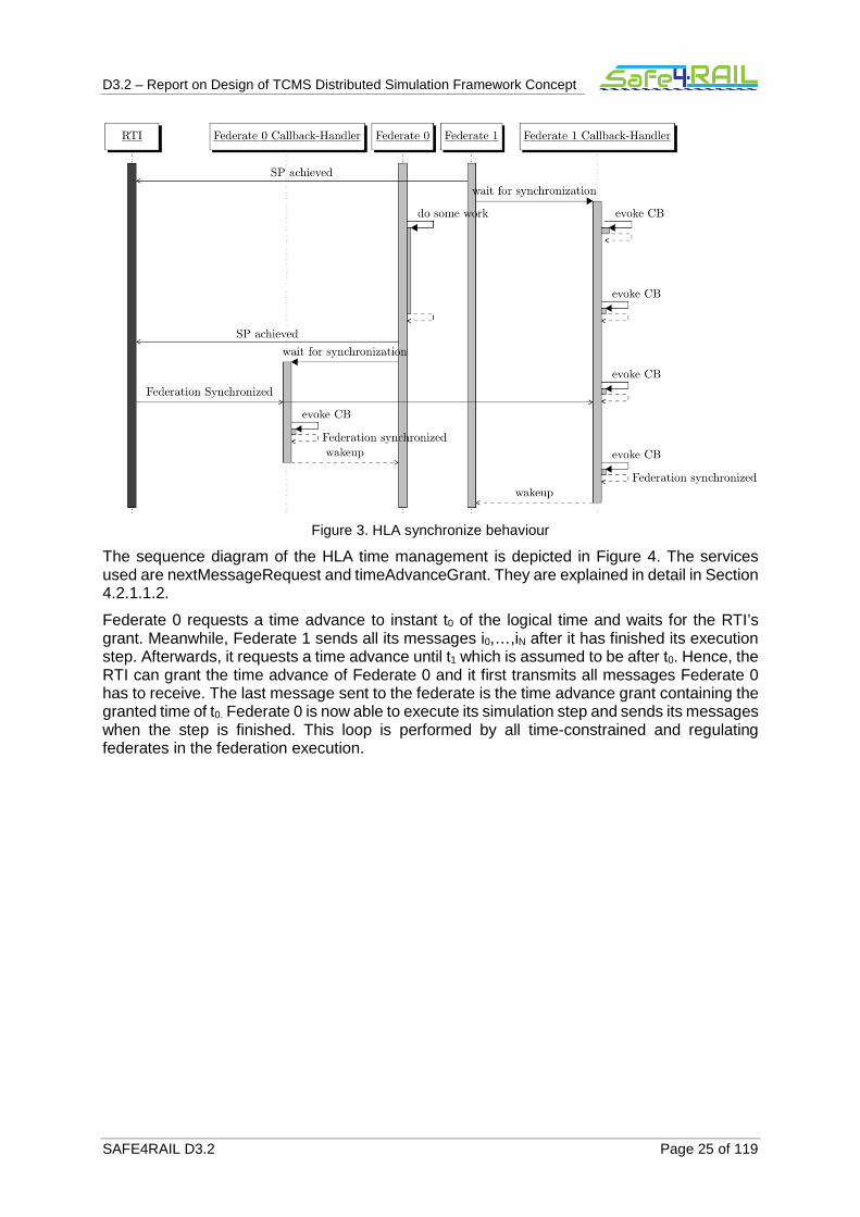
The sequence diagram of the HLA time management is depicted in Figure 4. The services used are nextMessageRequest and timeAdvanceGrant. They are explained in detail in Section 4.2.1.1.2.
Federate 0 requests a time advance to instant t0 of the logical time and waits for the RTI’s grant. Meanwhile, Federate 1 sends all its messages i0,…,iN after it has finished its execution step. Afterwards, it requests a time advance until t1 which is assumed to be after t0. Hence, the RTI can grant the time advance of Federate 0 and it first transmits all messages Federate 0 has to receive. The last message sent to the federate is the time advance grant containing the granted time of t0. Federate 0 is now able to execute its simulation step and sends its messages when the step is finished. This loop is performed by all time-constrained and regulating federates in the federation execution.

D3.2 – Report on Design of TCMS Distributed Simulation Framework Concept
SAFE4RAIL D3.2 Page 26 of 119
Figure 4. HLA time management
4.2.1.1.4 Time synchronization for SIL and HIL simulation
The time synchronization mechanism, explained in the previous sections, is used by the co-simulation entities to synchronize the simulation bridges to a common, logical simulation time. Thereby, there is no difference between SIL and HIL simulation. Figure 5 shows the scheduled tasks of an end device (part a) and the HLA services used to synchronize the end device with other end devices (part b).
The end device's schedule contains two tasks and 4 messages (see Figure 5, part a). The first task (T0) is time-triggered and starts at tick 3 (��������). It requires message M0 for its execution which is received at tick 2. At tick 5, it sends message M1 and based on its WCET the task finishes at tick 6 (����). In contrast, the event-triggered task T1 depends on the arrival of
message M2 which is received at tick 8 (��������). At its end at tick 10 (����), the task injects message M3 into the network.

D3.2 – Report on Design of TCMS Distributed Simulation Framework Concept
SAFE4RAIL D3.2 Page 27 of 119
Figure 5: Synchronization steps: a) scheduled tasks of end device, b) HLA services and synchronization steps
In Figure 5 part b, the schedule is used to explain the HLA time management services used to synchronize the end devices and how the simulation bridges advance in time. At first, only simulations without real end devices are considered. Starting at tick 0, the co-simulation module requests a time advance using the NextMessageRequest service until the scheduled beginning of T0 (step 1). This time represents the next event in the local event queue. However, the end device receives message M0 at tick 2 which is why only a time advance until this tick is granted (step 2). Since the reception of M0 does not trigger the execution of a task, the time advance request is repeated (step 3) and granted in step 4. At tick 3, the simulation tool can perform a simulation step to advance in time and execute T0 represented by the local event at tick 3. Using the SendInteraction service, message M1 which is produced by the task is sent with a time-stamp of 5. Afterwards, the simulation bridge requests the next time advance. Since message M2 is received at tick 8, the request is granted to this time and the dependent task T1 is executed sending M2 with time-stamp 10. Although the same time management services can be used if a real end device is connected to the simulation bridge in the HIL use-case, there are some differences compared to the SIL use-case. Those are explained in the following.
Since FMI is used to interface the simulation tools to the simulation bridges, the FMI function DoStep is used to trigger the execution of a simulation step until a specified time. Using StepFinished, the simulation tool signals the end of the execution. Afterwards, the simulation bridge can pull all messages from the simulation tool using the getXXX functions. However, most of the real end devices tested are related to real-time. They are executed in parallel to the simulation bridges and are connected via Ethernet. This is why the FMI functions are not used and other synchronization mechanisms between the end device and the simulation bridges have to be developed. The synchronization of the simulation bridges is realized using the HLA time management as described above.
1. All simulation tools are faster than the real end device
2. The real end device is faster than the rest of the simulation
2.1. The real end device is event-triggered
2.2. The real end device is time-triggered

D3.2 – Report on Design of TCMS Distributed Simulation Framework Concept
SAFE4RAIL D3.2 Page 28 of 119
Synchronizing the time advances of the end device depends on the features of the applications in the simulation and the end device itself. Usually, the slowest device determines the speed of the execution. Thereby, there is no difference whether the device is real or simulated. If the real end device is the slowest device in the simulation execution (see case 1 in the list above) so that all required data is received in time, there is no explicit synchronization mechanism required. The reason is that the other simulation bridges block their simulation tools until the time advances. This is the best case.
If the real end device is faster than the rest of the simulation (case 2), it does not receive the required data in time. Hence, the delays must be mitigated. The simplest case is when all tasks in the device are event-triggered and start when a message is received (case 2.1). In this case the end device is synchronized implicitly since it has to wait for the message arrival.
Time-triggered end devices (case 2.2) cannot be suspended in most cases. Often they are attached to I/O systems which need new control values continuously since otherwise the functionality would be affected. In this case, the real end device must receive the required data in time. To mitigate delays in the communication, a state estimation subsystem in the delay management estimates the required information which is then provided to the device.
The simulation bridge forwards messages destined to the real end device from the other federates in the simulation when the time advance is granted. After the reception, it has to forward the message to the device. Due to the relation to real-time, the device's current time must be synchronized with an image of the time in the synchronization bridge. Injecting the received message in the Ethernet link follows the required timing characteristics. On the other hand, the simulation bridge receives data messages from the device and converts them into HLA interactions. Those interactions are forwarded to the receiving federates using the HLA sendInteraction service as described above.
To signal the termination of a task in the end device there are two possible solutions. The first one is to define a bit in the Ethernet messages sent which denotes the last message created by the task. The other one would be sending an additional message signalling the termination. While the first possibility has the advantage that no further message has to be sent and the simulation bridge is notified as soon as possible, the second solution does not require the end device to know, which message is the last one executed in the task. However, the task needs to be finished if the message is sent at its end.
4.2.1.1.5 The HLA FOM
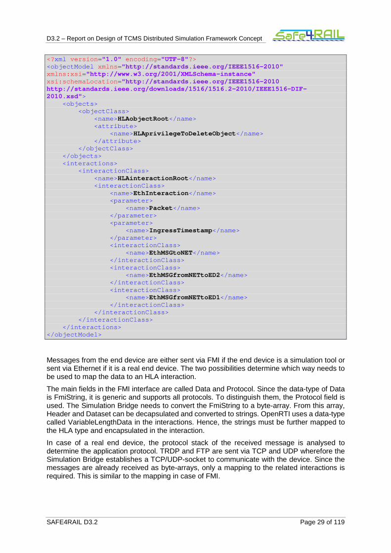
Messages in the HLA are called interactions defined in the Federation Object Model (FOM). The listing below shows the content of the FOM for the Communication's Emulator. Data is sent using the TRDP and FTP protocols between the different end devices wherefore an interaction class is defined for each protocol. Since there are different message types, the FOM defines an interaction class for each of them.
Due to the publish/subscribe concept of the HLA, a federate which subscribes to an interaction EthInteraction would receive every of those interactions even if it is not required. Hence there must be a possibility to distinguish the messages sent by the end devices which is solved exploiting the inheritance concept of the HLA. There are child-classes for each communication link between a sender and a receiver. However, the solution reduces the scalability of the framework if there are many devices. Since the end devices send their data to a network simulation federate first which relays the message to the receiving federate, all messages to the related network simulation federate can be pooled in one interaction class. This way, the resulting number of interaction classes depends on the number of network simulation federates. If there is only one of those federates, the number of interaction classes is reduced to the number of end devices receiving interactions plus one class for messages to the network simulation.
D3.2 – Report on Design of TCMS Distributed Simulation Framework Concept
SAFE4RAIL D3.2 Page 29 of 119
<?xml version ="1.0" encoding ="UTF-8"?> <objectModel xmlns ="http://standards.ieee.org/IEEE1516-2010" xmlns:xsi ="http://www.w3.org/2001/XMLSchema-instance" xsi:schemaLocation ="http://standards.ieee.org/IEEE1516-2010 http://standards.ieee.org/downloads/1516/1516.2-2010/IEEE1516-DIF-2010.xsd"> <objects> <objectClass> <name>HLAobjectRoot</name> <attribute> <name>HLAprivilegeToDeleteObject</name> </attribute> </objectClass> </objects> <interactions> <interactionClass> <name>HLAinteractionRoot</name> <interactionClass> <name>EthInteraction</name> <parameter> <name>Packet</name> </parameter> <parameter> <name>IngressTimestamp</name> </parameter> <interactionClass> <name>EthMSGtoNET</name> </interactionClass> <interactionClass> <name>EthMSGfromNETtoED2</name> </interactionClass> <interactionClass> <name>EthMSGfromNETtoED1</name> </interactionClass> </interactionClass> </interactionClass> </interactions> </objectModel>
Messages from the end device are either sent via FMI if the end device is a simulation tool or sent via Ethernet if it is a real end device. The two possibilities determine which way needs to be used to map the data to an HLA interaction.
The main fields in the FMI interface are called Data and Protocol. Since the data-type of Data is FmiString, it is generic and supports all protocols. To distinguish them, the Protocol field is used. The Simulation Bridge needs to convert the FmiString to a byte-array. From this array, Header and Dataset can be decapsulated and converted to strings. OpenRTI uses a data-type called VariableLengthData in the interactions. Hence, the strings must be further mapped to the HLA type and encapsulated in the interaction.
In case of a real end device, the protocol stack of the received message is analysed to determine the application protocol. TRDP and FTP are sent via TCP and UDP wherefore the Simulation Bridge establishes a TCP/UDP-socket to communicate with the device. Since the messages are already received as byte-arrays, only a mapping to the related interactions is required. This is similar to the mapping in case of FMI.

D3.2 – Report on Design of TCMS Distributed Simulation Framework Concept
SAFE4RAIL D3.2 Page 30 of 119
4.2.1.2 The Functional Mockup Interface
The Functional Mockup Interface (FMI) is a tool-independent standard. It is used for exchanging dynamic models or to co-simulate them [8]. It provides an interface which is implemented by more than 30 tools for version 1.0 and more than 25 tools for version 2.0 [9].
FMI mainly consists of two parts, the interfaces for Model Exchange (ME) and for the co-simulation. The first interface aims at the creation of a modelling environment which is able to generate C-code of a dynamic system model. Another simulation environment is hence able to use the generated code as an input/output block. In general, models are described by differential, algebraic and discrete equations with time-, state- and step-events. The second type of interfaces is used for co-simulation. In such environments, two or more simulation tools (slaves) are coupled by a master algorithm. This algorithm is responsible for the synchronization of the simulation tools and the exchange of data between them at discrete communication points. In between, the subsystems are solved independently by their own solver. If the master algorithm connects models for model exchange, it also solves the models [9]. Although FMI supports different algorithms, it does not define one in the standard [10]. As explained in D3.1, there are many solutions available which combine FMI with the HLA. The combination will also be used in the distributed co-simulation framework.
While there were different interfaces for both use-cases of FMI available in version 1.0, the main advantage of version 2.0 is the integration of both interfaces in one standard. Additionally, small details were improved and new features introduced. Hence, the usage of the standard is simplified and the performance is increased [11].
In the Distributed Simulation Framework, FMI 2.0 is used to communicate a simulation tool or an application (SIL) to the CESB. Table 1 shows the variables which are used to communicate between the ED and the CESB. The first column denotes the value and the second one presents its data-type. While column three points out the direction of the interface (from CESB to the ED, vice versa or both), column four describes the values.
Value Data-type Direction Description
Data FmiString Bidirectional The packet which is received or shall be sent. It is encoded as a Byte-Array in the CE and converted to an FmiString in the interface.
Protocol FmiInt Bidirectional Protocol denotes the protocol used to encapsulate the data. It is represented as a value from an enumeration.
Msg Send Timestamp MSBs
FmiInt Bidirectional Timestamp when the message has to be sent. Since a timestamp is 64bit and FmiInt 32bit (in standard C), this value represents the MSBs.
Msg Send Timestamp LSBs
FmiInt Bidirectional Timestamp when the message has to be sent. Since a timestamp is 64bit and FmiInt 32bit (in standard C), this value represents the LSBs.
Additional Data
According Fmi type
Bidirectional This value represents all variables which have to be configured, monitored or where faults can be injected. It has to be replaced by all those variables with the related data-types. They can be set (configuration) or got (monitoring) using FMI’s set and get functions.
D3.2 – Report on Design of TCMS Distributed Simulation Framework Concept
SAFE4RAIL D3.2 Page 31 of 119
Table 1: FMI variables for communication between CE and ED
4.2.2 Network simulator
Riverbed (former OPNET) is a powerful commercial network simulator which is widely used in the industry and academia to simulate and evaluate different communication layers, network elements and protocols. Due to widespread usage, Riverbed (former OPNET) evolves constantly to support a broader range of network protocols and technologies. In addition, Riverbed has a comprehensive Graphical User Interface (GUI) that enables the user to model a network topology from different levels of network (e.g. physical layer). The visual design of a network topology maps to real system implementation using object-oriented programming approach. Riverbed is a discrete-event triggered simulation tool. This means when a user develops a use case, the events simulate the system operation. This simulator also offers a programming technique to implement user-defined network protocols and message formats. To develop a customized network model in Riverbed, a user needs to specify node models and process models (which is a comprised state transmission machine)
Riverbed’s core functionalities are: modelling, simulating, and analysis. In Riverbed, the simulation results are presented in different readable forms (e.g. graphs, statistics). Some of Riverbed’s capabilities based on OPNET whitepaper can be listed as follow: parallel and event-triggered simulation kernel, powerful GUI for model development, user friendly debugging and data analysis tools, discrete event simulation engine, several standard component with source code, object-oriented modelling and open interface for importing external models [12], [13].
Since Riverbed (OPNET) is seen as a powerful simulation framework for the modelling and performance evaluation of a wide range of existing and future networks, we decide to use it for modelling the network simulator subsystems. Furthermore, prior simulation works (including TTEthernet) have been done in OPNET. Therefore, using OPNET as a simulation platform provides us an opportunity to simulate various wireless network setups with different time-triggered protocols. These modelling activities do not require any additional effort and simulation results can be analysed easily.
It could be mentioned also that external hardware or software can be connected directly to RIVERBED (former OPNET) using System In The Loop module.
In addition to these facts, our industry partners use Riverbed for their simulation activities. Thus, for integration and usability purposes it makes sense to use the similar simulation tool for our network simulator.
Nevertheless, although Riverbed has been selected for the network simulator, this tool may be replaced by another one (commercial or proprietary) to simulate the behaviour of several Ethernet switches connected in a TCMS network.
4.2.3 Communication Security
In order to secure the (network) communication channel between CESBs and the corresponding PC running RTI, the following protocols of VPN were under consideration:
• Point-to-Point Tunnelling Protocol (PPTP) – operates without certificate infrastructure
• Layer Two Tunnelling Protocol (L2TP) – strong authentication by means of user-level and computer-level authentication
• Internet Protocol Security (IPSec) – provides per packet data authentication, data integrity, replay protection and data confidentiality
• Secure Socket Tunnelling Protocol (SSTP) – breaches the geological boundary
• OpenVPN (SSL)

D3.2 – Report on Design of TCMS Distributed Simulation Framework Concept
SAFE4RAIL D3.2 Page 32 of 119
The latter will be considered in detail subsequently. OpenVPN represents a decisive software tool in the VPN market for a peer-to-peer connection, which emulates the properties of a private link. Due to the GNU General Public License (GPL), OpenVPN is commonly used on various operating systems in order to securely access remote facilities, while maintaining privacy of information. Among others, OpenVPN enables a secure authentication by means of a challenge-response procedure and pre-shared credentials, certificates or keys. The security of OpenVPN relies on the well-established OpenSSL library and therefore offers up to 256-bit AES key size for encryption of transmitted (communication) data [14].
For the communication channel between the CESB and the RTI, at least the following requirements shall be covered by the framework, respectively by the usage of OpenVPN:
• Enable secure communication for transmission of commands between federates/components.
• Ensure confidentiality, authenticity and integrity of (configuration) files as well as data transfer.
• Ensure communication channel between outstanding entities/PCs, e.g. between the graphical user interface and the framework with regards to threats and attacks.
4.2.3.1 Establishing Secure Tunnel
Both client and server use a specific tunnel data transfer protocol based on OpenSSL in order to establish a tunnel and transfer data successfully and securely. Before the main data transfer can be started, the sending entity (client or server) has to transmit a payload including a tunnel data transfer protocol header to the receiving entity. To be more accurate, the header includes the SSL version, the chosen cipher settings and session-specific data. Afterwards, the receiving entity, in the following the server, has to encapsulate the tunnel data transfer protocol header from the received data packet. Additionally, the server has to transmit its server information (cipher settings, session specific-data and certificate including public key) as well. Subsequently, the client will authenticate and validate the received certificate. Based on the result of the validation, the client has to create a pre-master secret (valid for the current session only) and perform an encryption by means of server’s public key provided within the certificate. Afterwards, the cipher of the session’s pre-master secret has to be transmitted to the server, whereupon the cipher is decrypted by means of server’s private key. Both the server and the client now have the ability to generate a symmetric session key based on the exchanged pre-master secret. The session key will be used for the succeeding communication (for en- and decryption of data packets), as long as the session is valid. To be in-line on both sides, an acknowledgement will be dispatched among themselves in order to use the session key only [14].
The tunnelling procedure behaves analogue in both direction. As mentioned before and depicted in Figure 6, the RTI is acting as a server, the federate as a client. However, the RTI, respectively the server, will initiate the establishment of the secure tunnel in the very first step and send an authentication invitation to the federate.

D3.2 – Report on Design of TCMS Distributed Simulation Framework Concept
SAFE4RAIL D3.2 Page 33 of 119
Figure 6. Establishing Secure Tunnel between RTI and Federate
D3.2 – Report on Design of TCMS Distributed Simulation Framework Concept
SAFE4RAIL D3.2 Page 34 of 119
Chapter 5 Architecture model
The architectural model represents the overall framework of the system to be implemented. It contains both structural and behavioural elements of the designed system. The architecture model of the CE is shown in Figure 7. Within it, the main component is the Central PC which contains the different modules that coordinate the execution of the co-simulation. Figure 8 presents these different modules.
• Communication module: is in charge of providing a secure communication for the different module of the PC. This communication is based on sockets or HLA messages.
• Communication’s Emulator Controller (CEC): is in charge of managing the execution of the simulation and providing the Network simulation if necessary. This means that the CEC is composed by its own sub-modules:
o Configuration Module: takes the configuration command from the CETSc and configures the other modules accordingly.
o Co-simulator Module: in charge of managing the HLA communication and synchronization.
o Network Simulator Module: provides the emulation of the network devices if no network devices are connected to the CE. Two options are available within this simulator:
� Network from the WP1: WP1 is focused on the creation of a solid foundation and concepts for a “Drive-by-Data” railway network architecture [15].
� ETB/ECN networks [16], [17], [TBC].
o Communication’s Emulator Simulation Bridge (CESB): Provide the communication of the Network Simulator Models with the different devices in the TCMS network.
o User Interface (UI): Provides an interface that allows the introduction of configuration files and CETS commands.
• Central Communication’s Emulator Toolset (CETSc): The CETSc is in charge of managing and validating the structure and configuration of the systems based on configuration files and messages receive from the CETSmaster and CETSslaves. In the other hand, the CETSc also provide the routing of the configuration and monitoring command from the CETSmaster to the corresponding CESBs.

D3.2 – Report on Design of TCMS Distributed Simulation Framework Concept
SAFE4RAIL D3.2 Page 35 of 119
Figure 7. Architecture model of the co-simulation framework.
deployment System Architecture
Heterogeneous Networks
Real ED 1 Real ED 2 Real ED 3
CE PC 1 CE PC 2
CE PC 3
Test Control PC 2
CETS (Slav e)
Simulation Host 1
Sim ED 4
Simulation Host 2
Sim ED 5 Sim ED 6
Central PC
CETS (C) CE (C)
Co-simulation Module
Network Simulator ModuleUI
Test Control PC 1
SFTS
CETS (Master)
CE1 (SB) CE2 (SB)
CE3 (SB)
CE4 (SB) CE5 (SB)
User
(from Actors)
Ethernet frames(Socket, HLA)
Ethernetwire
Ethernet wireEthernet wire
Ethernet frames(Socket, HLA)
Ethernet frames(Socket)
Ethernet frames(Socket, HLA)
Ethernet frames(Socket, HLA)
Ethernet frames(Socket, HLA)
Ethernet frames(Socket)
Ethernet frames(Socket)
I/O Ethernet wire
Ethernet frames(Socket, HLA)
I/O

D3.2 – Report on Design of TCMS Distributed Simulation Framework Concept
SAFE4RAIL D3.2 Page 36 of 119
Figure 8. Architecture model of Central PC
The Test Control PCs are another big part of the framework. These PCs allow the configuration and monitoring of the EDs in the network. There are two types of Test Control PCs depending on the type of CETS that they contain; slave PCs contain a CETSslave and master PCs contain the CETSmaster.
The main difference between the CETSmaster and CETSslave, is that the master provides the configuration and monitoring of distributed devices (these command are routed by the CETSc), meanwhile the slave can only interact with devices which are directly connected to the respective Test Control PC.
The CE cannot have more than one master at the same time.
Both CETSmaster and CETSslave follow the structure presented in Figure 9.
• Configurator Module: is in charge of managing the configuration of its corresponding CESBs.
• Monitoring Module: recollects the monitoring information of the different CESBs.
• Communication module: is in charge of providing a secure communication with the different elements of the CE.
deployment System Architecture
«device»Central PC
Communication Module
Communication Security Entity
CETS (C)
Configurator Module
Monitoring Module
CE (C)
Network Simulator
Co-simulation Module
Co-simulation Entity
Configuration Module
Network Simulator Module
Network Simulation Tool Entity
UI
UI Module
CE (SB) CE (SB)
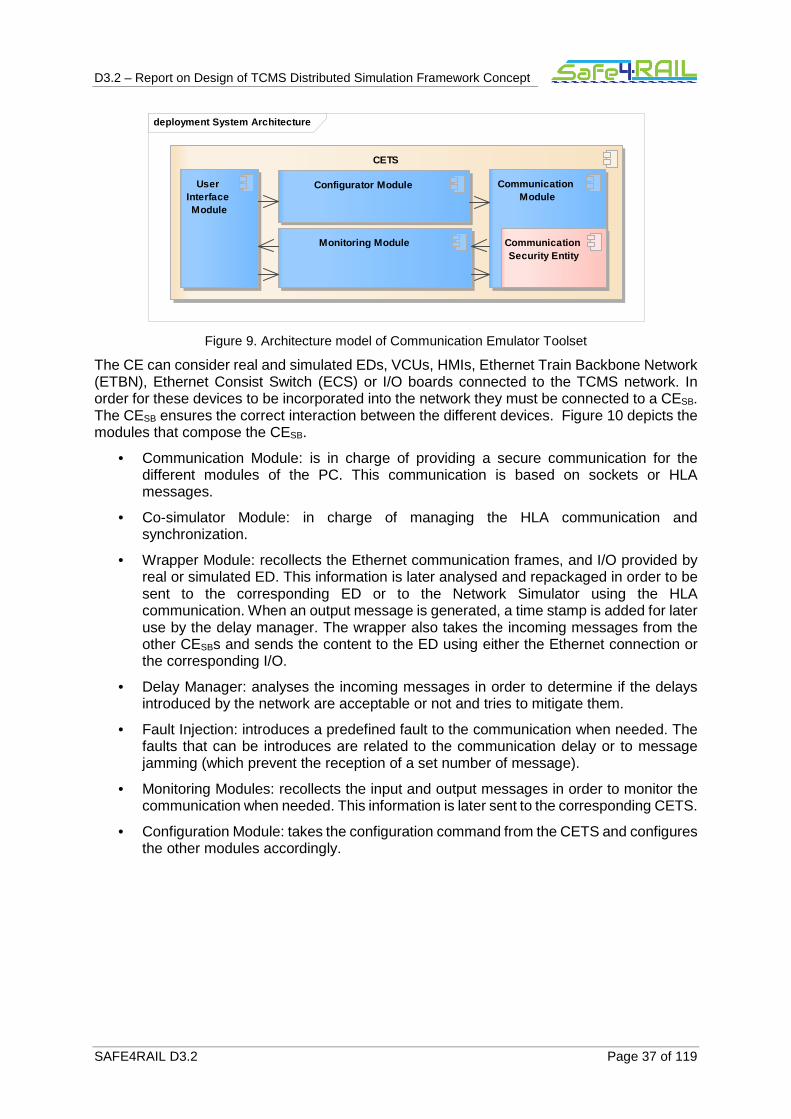
D3.2 – Report on Design of TCMS Distributed Simulation Framework Concept
SAFE4RAIL D3.2 Page 37 of 119
Figure 9. Architecture model of Communication Emulator Toolset
The CE can consider real and simulated EDs, VCUs, HMIs, Ethernet Train Backbone Network (ETBN), Ethernet Consist Switch (ECS) or I/O boards connected to the TCMS network. In order for these devices to be incorporated into the network they must be connected to a CESB. The CESB ensures the correct interaction between the different devices. Figure 10 depicts the modules that compose the CESB.
• Communication Module: is in charge of providing a secure communication for the different modules of the PC. This communication is based on sockets or HLA messages.
• Co-simulator Module: in charge of managing the HLA communication and synchronization.
• Wrapper Module: recollects the Ethernet communication frames, and I/O provided by real or simulated ED. This information is later analysed and repackaged in order to be sent to the corresponding ED or to the Network Simulator using the HLA communication. When an output message is generated, a time stamp is added for later use by the delay manager. The wrapper also takes the incoming messages from the other CESBs and sends the content to the ED using either the Ethernet connection or the corresponding I/O.
• Delay Manager: analyses the incoming messages in order to determine if the delays introduced by the network are acceptable or not and tries to mitigate them.
• Fault Injection: introduces a predefined fault to the communication when needed. The faults that can be introduces are related to the communication delay or to message jamming (which prevent the reception of a set number of message).
• Monitoring Modules: recollects the input and output messages in order to monitor the communication when needed. This information is later sent to the corresponding CETS.
• Configuration Module: takes the configuration command from the CETS and configures the other modules accordingly.
deployment System Architecture
CETS
User Interface Module
Configurator Module
Monitoring Module
Communication Module
Communication Security Entity

D3.2 – Report on Design of TCMS Distributed Simulation Framework Concept
SAFE4RAIL D3.2 Page 38 of 119
Figure 10. Architecture model of Communication’s Emulator Simulation Bridge
In order to provide the configuration and management of the simulated devices, the framework can contain either a UI (located in the central PC) or a SFTS. Both of these elements are connected to the different simulated ED by a CESB. This CESB routes the SFTS commands to the corresponding simulated EDs.
5.1 Interfaces
In the system, different interfaces should be taken into account. Firstly, the CE (CESB and CEC) exchanges HLA interactions via a heterogeneous network. This interface is used to exchange TCMS data or SFTS commands. Furthermore, the CETS (CETSmaster, CETSC and CETSslave) uses a socket to exchange managing data. Due to the fact that these two interfaces communicate via a heterogeneous network, a VPN is used in order to ensure security. The use of OpenVPN to do so has been discussed in Section 4.2.3.
5.1.1 Interface SFTS – CETS
The SFTS and the CETS processes run in the same PC, and they interact with each other by a TCP/IP socket. The SFTS sends commands to the CETS to configure the CE, and it receives a determined answer for some of these commands. All the available commands and their
deployment System Architecture
CE (SB)
Communication Module
CommunicationSecurity Entity
Configuration Module
Monitoring Module
Delay Management
Co-simulation Module
Co-simulation Entity
Wrapper Module
Federate Ambassador
RTI Ambassador
Fault Injection Module

D3.2 – Report on Design of TCMS Distributed Simulation Framework Concept
SAFE4RAIL D3.2 Page 39 of 119
corresponding answer are detailed in Table 2. Furthermore, in parenthesis, the parameters which every command demands are shown.
The configuration and reconfiguration commands require a file to configure the system. Thus, the SFTS should tell to the CETS the path of the desired file. If the system has been correctly configured, the CETS returns a Configured message; otherwise, the CETS returns an error.
The monitoring start and monitoring stop commands start and stop the monitoring of the CE signals/messages. The CETS should tell to the CETS the ID of the CESB to be monitored, and if the monitoring data should be save in a file or directly transmitted to the SFTS. The data saved in a file during a test is sent to the SFTS at the end of this test, when the simulation stop command is sent.
The configuration request command returns the configuration file which the system has received. The CETS receives this file and sends the file path to the SFTS.
When the SFTS sends a fault injection command (start or stop), the ID of the CESB and the fault type should be indicated.
Finally, after the simulation stop command is sent, the SFTS receives all the monitoring files (if any), and a stopped command indicating that the simulation has been stopped.
Commands from the SFTS to the CETS Answers from the CETS to the SFTS
Configure (configuration file path) Configured/Error
Reconfigure (reconfiguration file path) Configured/Error
Monitoring start (CESB ID, save in file?) -
Monitoring stop (CESB ID) -
Configuration request Configuration file (configuration file path)
Fault Injection start (CESB, fault type) -
Fault injection stop (CESB, fault type) -
Simulation stop Stopped
Table 2. Commands of the interface SFTS – CETS.
5.1.2 Interface SFTS – CE SB
This interface is used by the SFTS to command the SF. The SFTS sends the commands encapsulated in a TCP/IP frame, being the destination address the address of the SF which should receive the command.
The commands which the SFTS sends have to be defined by CONNECTA.
5.1.3 Interface Real ED – CE SB
This interface is an Ethernet or analog/digital I/Os which are connected directly to the CESB. The CESB will be seen by the real ED as the switch to which it would be connected in a real TCMS, being the CESB transparent for the real ED.

D3.2 – Report on Design of TCMS Distributed Simulation Framework Concept
SAFE4RAIL D3.2 Page 40 of 119
5.1.4 Interface SF (Sim. Tool) – CE SB
This interface sends a set of FMI commands or any other alternative commands via TCP/IP. These commands can be divided into:
• RTI commands:
o DoStep: ask the simulation tool to run up to a specified time.
o StepFinished: the simulation tool informs that a specified time has been reached.
o I_Orequest: ask the value of a specific I/O to the simulation tool.
o I_OMessageTraffic: the value of a specific I/O is sent to the simulation tool.
• Communication data:
o SFTS commands: sent by the SFT to command the functional behaviour of the simulation tool. As stated above, these commands should be defined by CONNECTA.
o Communications with the rest of the elements in the TCMS network.
• State estimator: FMI commands will be used to an external state estimator. More details about the state estimator and its interface are delved in Section 7.11.3.
5.2 Architectural requirements validation
This section presents the characteristics of the simulation framework that fulfil the architectural requirements.
• CESB creates a simulated channel for exchanging monitoring, configuration, analysis and troubleshooting data locally or remotely. The communication between the CESB is managed by a CEC (req. ID_20001).
• The introduction of CESB and CEC as part of the Local Communication Network (LCN) ensures remote and local communication between real and simulated system/subsystems (req. ID_20002).
Figure 11. LC replaced by RC using CE
• One or more systems/subsystems can be connected to a single CESB (req. ID_20003).
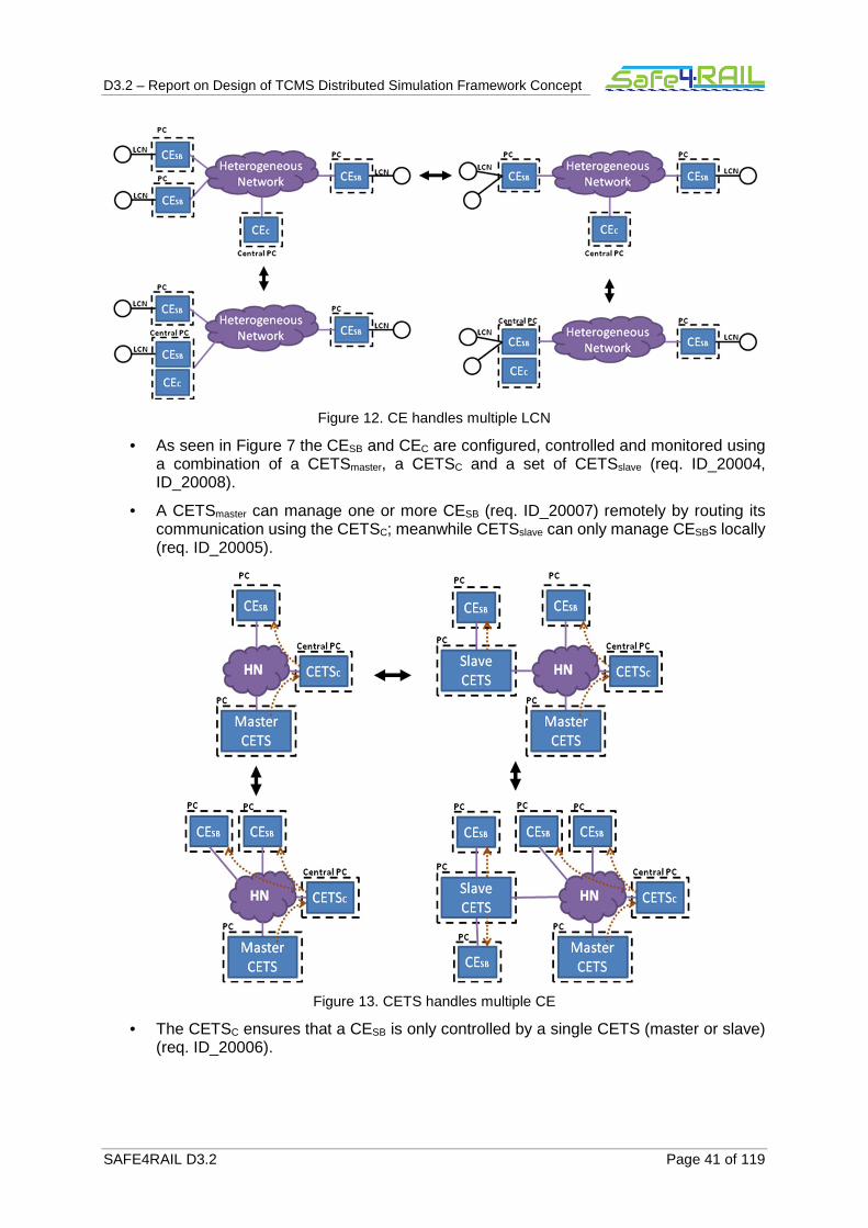
D3.2 – Report on Design of TCMS Distributed Simulation Framework Concept
SAFE4RAIL D3.2 Page 41 of 119
Figure 12. CE handles multiple LCN
• As seen in Figure 7 the CESB and CEC are configured, controlled and monitored using a combination of a CETSmaster, a CETSC and a set of CETSslave (req. ID_20004, ID_20008).
• A CETSmaster can manage one or more CESB (req. ID_20007) remotely by routing its communication using the CETSC; meanwhile CETSslave can only manage CESBs locally (req. ID_20005).
Figure 13. CETS handles multiple CE
• The CETSC ensures that a CESB is only controlled by a single CETS (master or slave) (req. ID_20006).

D3.2 – Report on Design of TCMS Distributed Simulation Framework Concept
SAFE4RAIL D3.2 Page 42 of 119
Figure 14. Only one CETS per CE
• The Simulation host can handle multiple EDs. (req. ID_20011)
Figure 15. SIM handles multiple EDS
• It is possible to distribute a system/subsystem between multiple simulation hosts and to connect those using CESBs (req. ID20012).
Figure 16. EDS distributable
• The simulation host is controlled by a SFTS. The commands of this tool set are sent across CE by using CESBs (req. ID_20013, ID_20016).
Figure 17. SFTS and SIM connection
• The CESB can be integrated into the simulation host (req. ID_20018)
Figure 18. CE integrated into SIM
• The CETS and SFTS can be combined into a single computer as seen in the Test Control PC 1 of Figure 7 (req. ID_20019).
• All communication and commands between the elements of the simulation follow the HLA communication protocol (req. ID_20020).
D3.2 – Report on Design of TCMS Distributed Simulation Framework Concept
SAFE4RAIL D3.2 Page 43 of 119
• All communication related to the simulation framework is performed over a heterogeneous network separated from the LCN (req. ID_20021)

D3.2 – Report on Design of TCMS Distributed Simulation Framework Concept
SAFE4RAIL D3.2 Page 44 of 119
Chapter 6 Dynamic model
The dynamic model defines the behaviour of the system taken as a whole. In simple terms it describes how the system reacts in response to external stimuli (which may come from humans or other systems). The diagram is depicted using a system state diagram.
The dynamic model for the CE is shown in Figure 19; it includes the different states of the system which are:
• Not configured: in this state the system has not been configured, and it is waiting for the Config command.
• Validated and connected: in this state the system has performed the validation of the configuration files, as well as it has connected and initialized the different CESBs and CETSslaves of the system.
• Configured: the registration of synchronization points and the configuration of the object and interactions (publication and subscription) used by the different federates has been performed.
• Started: the SF simulation has been started and it is executing the main loop. During this state the Reconfigure command may be sent, however, after this command the FOM and the number of federates cannot be changed. The Reconfigure command only changes the registered points and the published and subscribed objects and interactions.
• Stopped: the simulation has been stopped in order to configure the system using the Config command, this means that the FOM and the number of federates can be changed for the next test. During this state the monitoring files are collected from the corresponding CESB.
• Info requested: Collects the configuration file form the CETSC and present it to the UI.
• Configure Monitoring: Configures a CESB in order to provide the monitoring of the messages of the CESB. This monitoring sends the data directly to the UI or is stored in a monitoring file for later retrieval.
• Stop Monitoring: Stops the monitoring process on a specific CESB.
• Fault injection configured: The fault injection command including the fault type has been received by CESB and it has been started.
• Fault injection stopped The fault reset command indicating the fault type has been received by the CESB and this fault has been stopped.

D3.2 – Report on Design of TCMS Distributed Simulation Framework Concept
SAFE4RAIL D3.2 Page 45 of 119
Figure 19. Dynamic model of the Communication Emulator (CE).
stm Dynamic Model
EntryPoint
Info requested
Not configured
Validated and connected
Configured
Started
Configure Monitoring
Stop Monitoring
StoppedFault injection configured
Fault injection stopped
[Monitoring_stop]
[Config]
[Moniotring_start]
[Config ]
[Reconf (The same federates and setof interactions, different SP and
interaction subscriptions)]
[Stopped][Fault_reset][Fault_injection]
[Conf. info request]

D3.2 – Report on Design of TCMS Distributed Simulation Framework Concept
SAFE4RAIL D3.2 Page 46 of 119
Chapter 7 Subsystem model
The designed CE is composed of different subsystems, in this chapter a dynamic model is presented for each one. The different subsystems in the system are:
• User Interface subsystem.
• Configurator subsystem (Central).
• Configurator subsystem (Master/Slave).
• Configuration subsystem.
• Monitoring subsystem (Simulation Bridge).
• Monitoring subsystem (Central).
• Monitoring subsystem (Master/Salve).
• Communication subsystem (Central).
• Communication subsystem (Master/Slave, Simulation Bridge).
• Wrapper subsystem.
• Delay Manager subsystem.
• Fault injection subsystem
• Co-simulation subsystem.
• Network Simulator subsystem
Furthermore, all interactions among the different subsystems have been defined. These interactions are shown in the sequence diagrams in Chapter 12 Appendix I, in this chapter, the sequence diagrams where each subsystem appears are named.
7.1 User Interface Subsystem
The UI subsystem is located in the CETSc and is in charge of interacting with the user. Its dynamic model is shown in Figure 20. The UI subsystem received the commands from the user, changing its state among:
• Not configured: The system is waiting for an external user to configure it.
• Configure file selected: The Configure command has been received and the configuration file has been ordered to the user.
• Configure file received: The configuration file has been received from the user and it has been sent to the Configurator subsystem.
• Configured and running: The whole system has been configured and it is running now, this new state has been reported to the user.
• Fault injection cmd received: The fault_start or fault_reset command has been received from the user and it has been sent to the Fault injection subsystem.
• Monitoring cmd received: The Monitoring_start or Monitoring_stop command has been received from the user and it has been sent to the Monitoring subsystem.
• Monitoring data received: The CETSmaster has received monitoring data from a CESB, and it has been sent to the user.
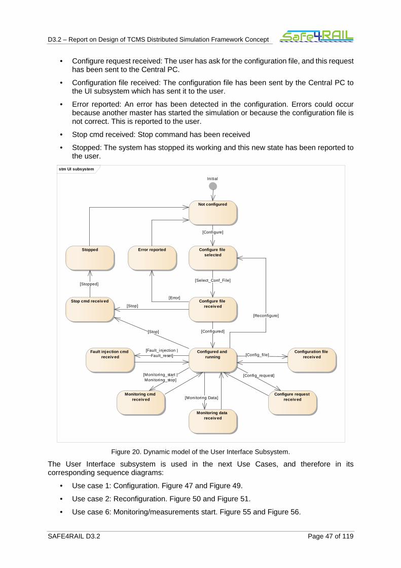
D3.2 – Report on Design of TCMS Distributed Simulation Framework Concept
SAFE4RAIL D3.2 Page 47 of 119
• Configure request received: The user has ask for the configuration file, and this request has been sent to the Central PC.
• Configuration file received: The configuration file has been sent by the Central PC to the UI subsystem which has sent it to the user.
• Error reported: An error has been detected in the configuration. Errors could occur because another master has started the simulation or because the configuration file is not correct. This is reported to the user.
• Stop cmd received: Stop command has been received
• Stopped: The system has stopped its working and this new state has been reported to the user.
Figure 20. Dynamic model of the User Interface Subsystem.
The User Interface subsystem is used in the next Use Cases, and therefore in its corresponding sequence diagrams:
• Use case 1: Configuration. Figure 47 and Figure 49.
• Use case 2: Reconfiguration. Figure 50 and Figure 51.
• Use case 6: Monitoring/measurements start. Figure 55 and Figure 56.
stm UI subsystem
Initial
Configure file selected
Configure file receiv ed
Configured and running
Not configured
Error reported
Monitoring cmd receiv ed
Configure request receiv ed
Monitoring data receiv ed
Configuration file receiv ed
Stop cmd receiv ed
Stopped
Fault injection cmd receiv ed
[Stop]
[Config_request]
[Fault_injection |Fault_reset]
[Stop]
[Configured]
[Reconfigure]
[Config_file]
[Monitoring_start |Monitoring_stop]
[Stopped]
[Configure]
[Select_Conf_File]
[Monitoring Data]
[Error]

D3.2 – Report on Design of TCMS Distributed Simulation Framework Concept
SAFE4RAIL D3.2 Page 48 of 119
• Use case 7: Monitoring/measurements stop. Figure 57 and Figure 58.
• Use case 8: Configuration data request. Figure 59.
• Use case 9: Simulation stop. Figure 60.
• Use case 10: Fault injection start. Figure 61 and Figure 62
• Use case 11: Fault injection stop. Figure 63 and Figure 64
7.2 Configurator Subsystem (Central)
The configurator subsystem (central) is located in the CETSc and is in charge of receiving the configuration file and analyse it. Then, the configuration data is sent to the different CETSslaves and CESBs in the simulation. The different states in the model are:
• Not configured: The system is waiting for an external user for configuration.
• Error reported: An error has been detected in the configuration. In this state errors can only occur because the configuration file is not correct.
• Configure cmd received: The Configure command and the configuration have been received. They have been sent to the configuration subsystem to configure the Co-simulation subsystem and the Network simulator subsystem. The subsystem is waiting for the CETSc to be configured.
• Central PC configured: The Co-simulation subsystem, the Monitoring subsystem and the Network simulator subsystem have been configured and they have confirmed it. The CETSslaves are requested to send their configuration file.
• Configure file received: A CETSslave has sent the configuration file and the CETSc has received it.
• Controlled CESBs information request: The Central PC has requested to the CETSslaves which CESBs they are going to control.
• Controlled CESBs settled: Each CETSslaves has reported to the CETSc which CESBs it is going to control in the simulation and the CETSc has sent to the CETSslaves and the CETSmaster which CESBs are under their control.
• Configuration information sent to the CESB: The configuration information has been sent to the CESBs associated to the CETSmaster.
• Configured and running: The whole system has been configured and it is running now, this new state has been reported to the UI subsystem.
• Fault injection started: The fault injection command has been received and it has been routed to the corresponding CESB.
• Fault injection reset: The fault reset command has been received and it has been routed to the corresponding CESB.
• Reconfigure cmd received: The reconfigure command has been received and it has been sent to the Co-simulation subsystem and the Network simulator subsystem.
• Configured: The CETSc has been reconfigured. The reconfigure command and the reconfiguration file have been sent to the CE.
• Stop cmd received: The Stop command has been received and it has been sent to the Network simulator subsystem.
• Central PC stopped: The CETSc has been stopped. Every CE and CETS is told to stop the simulation.

D3.2 – Report on Design of TCMS Distributed Simulation Framework Concept
SAFE4RAIL D3.2 Page 49 of 119
• CE or CETS stopped: A CE or a CETS confirmed its simulation is stopped.
• Stopped reported: The subsystem reports that the simulation has been stopped.

D3.2 – Report on Design of TCMS Distributed Simulation Framework Concept
SAFE4RAIL D3.2 Page 50 of 119
Figure 21. Dynamic model of the Configurator (Central) Subsystem.
The configurator subsystem (central) is used in the next Use Cases, and therefore in its corresponding sequence diagrams:
stm Configurator
Initial
Not configured
Configure cmd receiv ed
Central PC configured
Configure file receiv ed
More CETS to sent i tsconfig fi le?
Controlled CE(SB)s information request
Controlled CE(SB)s setled
More CETS tosent i ts CE
(SB)?
Configuration information sent to
the CE(SB)
Configured and running
Reconfigure cmd receiv ed
Configured
Error reported
Error reported Stop cmd receiv ed
Central PC stopped
CE(SB) or CETS stopped
More CE(SB) orCETS to confirm their
stop?
Stopped reported
Fault injection started Fault injection reset
[Configure &config_file_wrong]
[YES]
[NO]
[Configure]
[YES]
[Stopped]
[Configure &config_fi le_correct]
[Fault_injection]
[Configured]
[Configured]
[Configured]
[Fault_reset]
[Configured]
[YES]
[NO]
[Configured]
[Configure &config_fi le_correct]
[Configure &config_fi le_wrong]
[Stopped]
[Stop]

D3.2 – Report on Design of TCMS Distributed Simulation Framework Concept
SAFE4RAIL D3.2 Page 51 of 119
• Use case 1: Configuration. Figure 47 and Figure 49.
• Use case 2: Reconfiguration. Figure 50 and Figure 51.
• Use case 8: Configuration data request. Figure 59.
• Use case 9: Simulation stop. Figure 60.
• Use case 10: Fault injection start. Figure 61
• Use case 11: Fault injection stop. Figure 63
7.2.1 Configuration file
This files contains the configuration data that defines the CETSs (master and slave), the RTI communication (federates, interaction, FOM file, Synchronization points) and the Network Simulator.
<CommunicationEmulator> <!-- Defines the different Communication Emulator T ool Sets --> <CommunicationEmulatorToolSets> <!-- CETS information - id: CETS identifier - type: defines if the CETS is a master or a slave - ip: ip address of the CETS --> <CETS id ="CETSmaster" type ="master" ip ="192.168.0.100"/> <CETS id ="CETSslave" type ="slave" ip ="192.168.0.101"/> ... </CommunicationEmulatorToolSets> <!-- Defines the federation information - executionName: Name of the Federation executi on - RTIip: ip of the RTI node that manage the HLA communiation--> <Federation executionName ="TCMSnetwork" RTIip ="192.168.0.1"> <!-- Number od federates in the federation --> <NumberofFederate> 8</NumberofFederate> <!-- Federate information - id: Federate identifier - isTimeConstrained: Is the federate time c onstrained? - isTimeRegulating: Is the federate time re gulating? - ip: ip address of the federate use for co nfiguration - CETSid: id of the CETS which control and monitors the federate - lookahead: lookahead used by the HLA for synchronization--> <Federate id ="SimulationBridge1" isTimeConstrained ="false" isTimeRegulating ="false" ip ="192.168.0.2" CETSid ="CETSslave" lookahead ="0.1"> <!-- Definition of Hardware In The Loop ED. there can be more than one. - id: ED identifier - ip: ED ip address for communication - maxCommLatency: Maximum latency for c ommunication between simulation bridge and end device (in ms). Used for calculation of time for NextMessageRequest--> <HIL id ="EndDevice1" ip ="192.168.0.4" maxCommLatency="100"> <!-- Interactions which the federate is subscribed/published. All HIL devices have an interaction for the receiving Ethernet frames, an interaction form sending Ethern et frames, an interaction for each input variables and an interac tion for each output variables--> <Interactions> <!-- Interaction definition - id: Interaction identifier
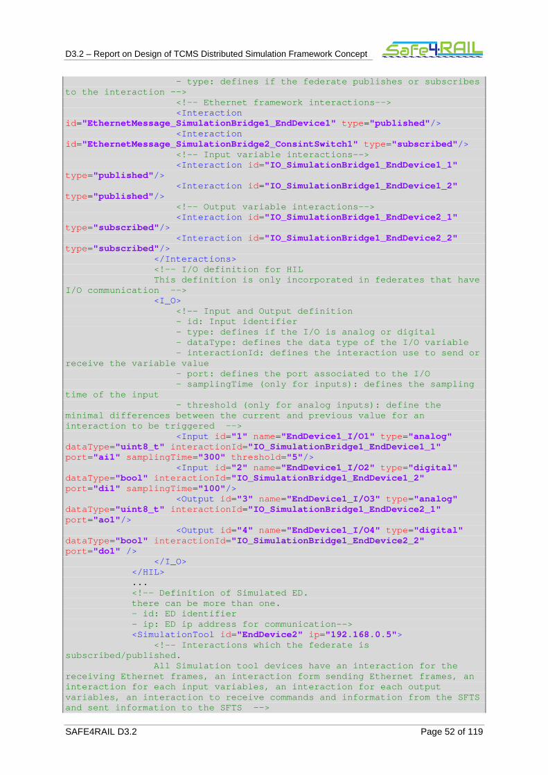
D3.2 – Report on Design of TCMS Distributed Simulation Framework Concept
SAFE4RAIL D3.2 Page 52 of 119
- type: defines if the federate publishes or subscribes to the interaction --> <!-- Ethernet framework interactions--> <Interaction id ="EthernetMessage_SimulationBridge1_EndDevice1" type ="published"/> <Interaction id ="EthernetMessage_SimulationBridge2_ConsintSwitch1" type ="subscribed"/> <!-- Input variable interactions--> <Interaction id ="IO_SimulationBridge1_EndDevice1_1" type ="published"/> <Interaction id ="IO_SimulationBridge1_EndDevice1_2" type ="published"/> <!-- Output variable interactions--> <Interaction id ="IO_SimulationBridge1_EndDevice2_1" type ="subscribed"/> <Interaction id ="IO_SimulationBridge1_EndDevice2_2" type ="subscribed"/> </Interactions> <!-- I/O definition for HIL This definition is only incorporate d in federates that have I/O communication --> <I_O> <!-- Input and Output definition - id: Input identifier - type: defines if the I/O is a nalog or digital - dataType: defines the data ty pe of the I/O variable - interactionId: defines the in teraction use to send or receive the variable value - port: defines the port associ ated to the I/O - samplingTime (only for inputs ): defines the sampling time of the input - threshold (only for analog in puts): define the minimal differences between the current and previou s value for an interaction to be triggered --> <Input id ="1" name="EndDevice1_I/O1" type ="analog" dataType ="uint8_t" interactionId ="IO_SimulationBridge1_EndDevice1_1" port ="ai1" samplingTime ="300" threshold ="5"/> <Input id ="2" name="EndDevice1_I/O2" type ="digital" dataType ="bool" interactionId ="IO_SimulationBridge1_EndDevice1_2" port ="di1" samplingTime ="100"/> <Output id ="3" name="EndDevice1_I/O3" type ="analog" dataType ="uint8_t" interactionId ="IO_SimulationBridge1_EndDevice2_1" port ="ao1"/> <Output id ="4" name="EndDevice1_I/O4" type ="digital" dataType ="bool" interactionId ="IO_SimulationBridge1_EndDevice2_2" port ="do1" /> </I_O> </HIL> ... <!-- Definition of Simulated ED. there can be more than one. - id: ED identifier - ip: ED ip address for communication-- > <SimulationTool id ="EndDevice2" ip ="192.168.0.5"> <!-- Interactions which the federate is subscribed/published. All Simulation tool devices have an interaction for the receiving Ethernet frames, an interaction form send ing Ethernet frames, an interaction for each input variables, an interactio n for each output variables, an interaction to receive commands and i nformation from the SFTS and sent information to the SFTS -->

D3.2 – Report on Design of TCMS Distributed Simulation Framework Concept
SAFE4RAIL D3.2 Page 53 of 119
<Interactions> <!-- Interaction definition - id: Interaction identifier - type: defines if the federate publishes or subscribes to the interaction --> <!-- Ethernet framework interactions--> <Interaction id ="EthernetMessage_SimulationBridge1_EndDevice2" type ="published"/> <Interaction id ="EthernetMessage_SimulationBridge2_ConsintSwitch2" type ="subscribed"/> <!-- Input variable interactions--> <Interaction id ="IO_SimulationBridge1_EndDevice2_1" type ="published"/> <Interaction id ="IO_SimulationBridge1_EndDevice2_2" type ="published"/> <!-- Output variable interactions--> <Interaction id ="IO_SimulationBridge1_EndDevice1_1" type ="subscribed"/> <Interaction id ="IO_SimulationBridge1_EndDevice1_1" type ="subscribed"/> <!-- SFTS communication interactions--> <Interaction id ="SFTSCommunication_SimulationBridge3_SFTS" type ="subscribed"/> <Interaction id ="SFTSCommunication_SimulationBridge1_EndDevice2" type ="published"/> </Interactions> <!-- I/O definition for Simulation Tool This definition is only incorporate d in federates that have I/O communication --> <I_O> <!-- Input and Output definition - id: Input identifier - type: defines if the I/O is a nalog or digital - dataType: defines the data ty pe of the I/O variable - interactionId: defines the in teraction use to send or receive the variable value - real: defines if the Simulati onBrige has a real I/O board or if the value of the I/O is transmitted usi ng a Ethernet frame - port (only for real I/O): def ines the port associated to the I/O--> <Input id ="1" name="EndDevice2_I/O1" type ="analog" dataType ="uint8_t" interactionId ="IO_SimulationBridge1_EndDevice2_1" real ="false"/> <Input id ="2" name="EndDevice2_I/O2" type ="digital" dataType ="bool" interactionId ="IO_SimulationBridge1_EndDevice2_2" real ="true" port ="di1"/> <Output id ="3" name="EndDevice2_I/O3" type ="analog" dataType ="uint16_t" interactionId ="IO_SimulationBridge1_EndDevice1_1" real ="false" /> <Output id ="4" name="EndDevice2_I/O4" type ="digital" dataType ="bool" interactionId ="IO_SimulationBridge1_EndDevice1_2" real ="true" port ="do1"/> </I_O> <!-- Definition of synchronization and communicatio n commands. This element only appears in Simula tion Tools that do not implement the FMI standard. It defines the different commands u se by the SB to communicate and synchronize the execution of a simu lated ED

D3.2 – Report on Design of TCMS Distributed Simulation Framework Concept
SAFE4RAIL D3.2 Page 54 of 119
- bigEndian: defines if the values send/received during the I/O communication follows the big endian (true) or little endian (false) structure --> <CommandSet bigEndian ="true"> <!-- Do Step command definition Ask the Simulation Tool to run up to the specified time - commandId: defines the identi fier that characterized the do step command messages - dataType: defines the data ty pe use for specifying the step time - timeUnit: define the type uni t use in the step time --> <DoStep commandId ="33" dataType ="uint64_t" timeUnit ="millisecond"/> <!-- Step finish command definition The Simulation Tools informs th at the specified time has been reach - commandId: defines the identi fier that characterized the step finish command messages --> <StepFinish commandId ="34"/> <!-- Data Message Traffic definition Used for encapsulating Ethernet messages. If the Simulation tool does not require the encapsulation of the Etmernet message this element should not be defined. - commandId: defines the identi fier that characterized the Ethernet messages data. --> <DataMessageTraffic commandId ="45"/> <!-- I/O request command definition Ask the Simulation Tool of the value of a spesific I/O. If the Simulation tool does not provide I/O values via Ethernet communication this element should not be d efined. - commandId: defines the identi fier that characterized the I/O request command messages --> <I_Orequest commandId ="38"/> <!-- I_O Message Traffic definition Used for encapsulating I/O valu es. If the Simulation tool does not provide I/O values via Ethernet communication this element should not be d efined. - commandId: defines the identi fier that characterized the I/O messages data. --> <I_OMessageTraffic commandId ="48"/> </CommandSet> </SimulationTool> <SimulationTool id ="EndDevice3" ip ="192.168.0.6"> <Interactions> ... </Interaction> <I_O> ... </I_O> <!-- FMI configuration If FMI is used to connect a simulat ion, the simulation and additional data such as its FMI description file ar e encapsulated as FMU. During the simulation execution, the FMU is extract ed to a temporary folder in the same location. An empty string signals that FMI is not used.--> <FMI> <!-- FMU path: Path where the simulation’s FMU is located--> <FMU path ="../FMI/EndDevice3/"/> </FMI> </SimulationTool>
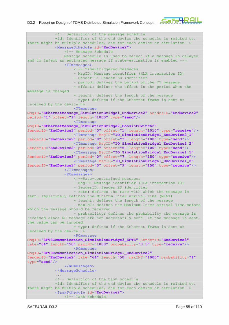
D3.2 – Report on Design of TCMS Distributed Simulation Framework Concept
SAFE4RAIL D3.2 Page 55 of 119
<!-- Definition of the message schedule -id: Identifier of the end device the s chedule is related to. There might be multiple schedules, one for each dev ice or simulation--> <MessageSchedule id ="EndDevice2"> <!-- Message Schedule Message schedule is used to detect if a message is delayed and to inject an estimated message if state-estimat ion is enabled --> <TTmessages> <!-- Time-triggered messages - MsgID: Message identifier (HL A interaction ID) - SenderID: Sender ED identifie r - period: defines the period of the TT message - offset: defines the offset in the period when the message is changed - lenght: defines the length of the message - type: defines if the Ethernet frame is sent or received by the device--> <TTmessage MsgID="EthernetMessage_SimulationBridge1_EndDevice2" SenderID ="EndDevice2" period ="1" offset ="1" length ="1000" type ="send"/> <TTmessage MsgID="EthernetMessage_SimulationBridge2_ConsintSwitch2" SenderID ="EndDevice3" period ="0" offset ="1" length ="1010" type ="receive"/> <TTmessage MsgID="IO_SimulationBridge1_EndDevice2_1" SenderID ="EndDevice2" period ="0" offset ="3" length ="100" type ="send"/> <TTmessage MsgID="IO_SimulationBridge1_EndDevice2_2" SenderID ="EndDevice2" period ="0" offset ="5" length ="100" type ="send"/> <TTmessage MsgID="IO_SimulationBridge1_EndDevice1_1" SenderID ="EndDevice3" period ="0" offset ="7" length ="150" type ="receive"/> <TTmessage MsgID="IO_SimulationBridge1_EndDevice1_2" SenderID ="EndDevice3" period ="0" offset ="9" length ="150" type ="receive"/> </TTmessages> <RCmessages> <!--Rate-constrained messages - MsgID: Message identifier (HL A interaction ID) - SenderID: Sender ED identifie r - rate: defines the rate with w hich the message is sent. Implicitely defines the Minimum Inter-arrival Time (MINT) - lenght: defines the length of the message - maxINT: defines the Maximum I nter-arrival Time before which the message should be received - probability: defines the prob ability the message is received since RC message are not necessarily sent. If the message is sent, the value can be ignored. - type: defines if the Ethernet frame is sent or received by the device--> <RCmessage MsgID="SFTSCommunication_SimulationBridge3_SFTS" SenderID ="EndDevice3" rate ="64" length ="50" maxINT="1000" probability ="0.5" type ="receive"/> <RCmessage MsgID="SFTSCommunication_SimulationBridge1_EndDevice2" SenderID ="EndDevice2" rate ="64" length ="50" maxINT="1000" probability ="1" type ="send"/> </RCmessages> </MessageSchedule> ... <!-- Definition of the task schedule -id: Identifier of the end device the s chedule is related to. There might be multiple schedules, one for each dev ice or simulation--> <TaskSchedule id ="EndDevice2"> <!-- Task schedule
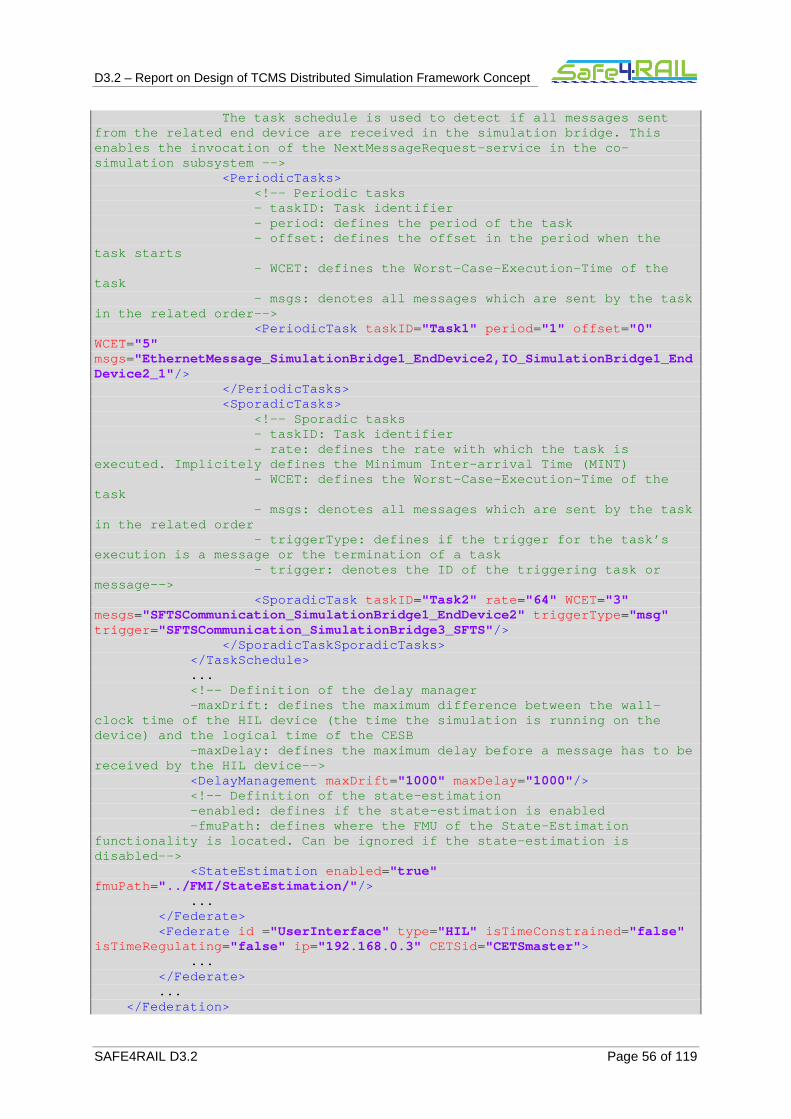
D3.2 – Report on Design of TCMS Distributed Simulation Framework Concept
SAFE4RAIL D3.2 Page 56 of 119
The task schedule is used to detect if all messages sent from the related end device are received in the sim ulation bridge. This enables the invocation of the NextMessageRequest-se rvice in the co-simulation subsystem --> <PeriodicTasks> <!-- Periodic tasks - taskID: Task identifier - period: defines the period of the task - offset: defines the offset in the period when the task starts - WCET: defines the Worst-Case- Execution-Time of the task - msgs: denotes all messages wh ich are sent by the task in the related order--> <PeriodicTask taskID ="Task1" period ="1" offset ="0" WCET="5" msgs="EthernetMessage_SimulationBridge1_EndDevice2,IO_SimulationBridge1_EndDevice2_1"/> </PeriodicTasks> <SporadicTasks> <!-- Sporadic tasks - taskID: Task identifier - rate: defines the rate with w hich the task is executed. Implicitely defines the Minimum Inter-arr ival Time (MINT) - WCET: defines the Worst-Case- Execution-Time of the task - msgs: denotes all messages wh ich are sent by the task in the related order - triggerType: defines if the t rigger for the task’s execution is a message or the termination of a task - trigger: denotes the ID of th e triggering task or message--> <SporadicTask taskID ="Task2" rate ="64" WCET="3" mesgs="SFTSCommunication_SimulationBridge1_EndDevice2" triggerType ="msg" trigger ="SFTSCommunication_SimulationBridge3_SFTS"/> </SporadicTaskSporadicTasks> </TaskSchedule> ... <!-- Definition of the delay manager -maxDrift: defines the maximum differen ce between the wall-clock time of the HIL device (the time the simulati on is running on the device) and the logical time of the CESB -maxDelay: defines the maximum delay be fore a message has to be received by the HIL device--> <DelayManagement maxDrift ="1000" maxDelay ="1000"/> <!-- Definition of the state-estimation -enabled: defines if the state-estimati on is enabled -fmuPath: defines where the FMU of the State-Estimation functionality is located. Can be ignored if the sta te-estimation is disabled--> <StateEstimation enabled ="true" fmuPath ="../FMI/StateEstimation/"/> ... </Federate> <Federate id = "UserInterface" type ="HIL" isTimeConstrained ="false" isTimeRegulating ="false" ip ="192.168.0.3" CETSid ="CETSmaster"> ... </Federate> ... </Federation>
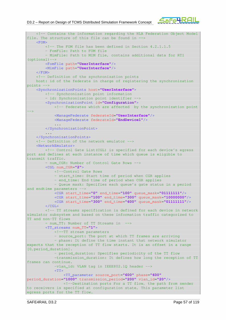
D3.2 – Report on Design of TCMS Distributed Simulation Framework Concept
SAFE4RAIL D3.2 Page 57 of 119
<!-- Contains the information regarding the HLA Fed eration Object Model file. The structure of this file can be found in -- > <FOM> <!-- The FOM file has been defined in Section 4.2.1 .1.5 - FomFile: Path to FOM file - MimFile: Path to MIM file, contains addit ional data for RTI (optional)--> <FomFile path ="UserInterface"/> <MimFile path ="UserInterface"/> </FOM> <!-- Definition of the synchronization points host: id of the federate in charge of registeri ng the synchronization points --> <SynchronizationPoints host ="UserInterface"> <!-- Synchronization point information - id: Synchronization point identifier --> <SynchronizationPoint id ="Configuration"> <!-- Federates which are affected by the synchroni zation point --> <ManageFederate federateId ="UserInterface"/> <ManageFederate federateId ="EndDevice1"/> ... </SynchronizationPoint> ... </SynchronizationPoints> <!-- Definition of the network emulator --> <NetworkEmulator> <!-- Control Gate List(CGL) is specified for each d evice’s egress port and defines at each instance of time which que ue is eligible to transmit traffic. - num_CGR: Number of Control Gate Rows --> <CGL num_CGR="2"> <!--Control Gate Rows - start_time: Start time of period when CGR applies - end_time: End time of period when CGR applies - Queue mask: Specifies each queue’s ga te status in a period and endtime parameters --> <CGR start_time ="0" end_time ="100" queue_mask ="01111111"/> <CGR start_time ="100" end_time ="300" queue_mask ="10000000"/> <CGR start_time ="300" end_time ="600" queue_mask ="01111111"/> </CGL> <!-- TT streams specification is defined for each d evice in network simulator subsystem and based on these information traffic categorized to TT and non-TT flows - num_TT: Number of TT Streams in --> <TT_streams num_TT="1"> <!--TT stream parameters - source_port: The port at which TT fra mes are arriving - phase: It define the time instant tha t network simulator expects that the reception of TT flow starts. It is an offset in a range [0,period_duration]. - period_duration: Specifies periodicit y of the TT flow -transmission_duration: It defines how long the reception of TT frames can continue. -vlan_id: VLAN tag in IEEE802.1Q header --> <TT> <TT_parameter source_port ="600" phase ="600" period_duration ="1000" transmission_period ="200" vlan_id ="20"/> <!--Destination ports For a TT flow, the path from sender to receivers is specified at configuration state, T his parameter list egress ports for the TT flow.

D3.2 – Report on Design of TCMS Distributed Simulation Framework Concept
SAFE4RAIL D3.2 Page 58 of 119
- num_dest_ports: Number of egress ports -port_id: Id of destination port -- > <dest_ports num_dest_ports ="1"> <port id ="10"/> </dest_ports> </TT> </TT_streams> <!-- Definition of the switch configuration --> <SwitchConfiguration> <node name="TSN_switch1" min_match_score ="strict matching" ignore_questions ="true" model ="ethernet16_switch_adv_tsn"> <ext-attr name="config_file" type ="string"> <default-value value =""/> </ext-attr> <ext-attr name="CGL_file" type ="string"> </ext-attr> <attr name="Bridge Parameters.count" value ="1"/> <attr name="Bridge Parameters [0].QoS Parameters.count" value ="1"/> <attr name="Bridge Parameters [0].QoS Parameters [0].QoS Support" value ="Enabled" symbolic ="true"/> <attr name="Bridge Parameters [0].QoS Parameters [0].Default Port QoS Scheme" value ="Strict Priority" symbolic ="true"/> <attr name="Bridge Parameters [0].QoS Parameters [0].Default Port Queue Configuration.count" value ="8"/> <attr name="Bridge Parameters [0].QoS Parameters [0].Default Port Queue Configuration [0].Priority" value ="0"/> <attr name="Bridge Parameters [0].QoS Parameters [0].Default Port Queue Configuration [0].Mapped User Priority Values.count" value ="1"/> <attr name="Bridge Parameters [0].QoS Parameters [0].Default Port Queue Configuration [0].Mapped User Priority Values [0].User Priority" value ="0 (Best Effort) - Default Priority" symbolic ="true"/> <attr name="Bridge Parameters [0].QoS Parameters [0].Default Port Queue Configuration [0].Priority Queue" value ="Yes" symbolic ="true"/> <attr name="Bridge Parameters [0].QoS Parameters [0].Default Port Queue Configuration [0].Weight" value ="20"/> <attr name="Bridge Parameters [0].QoS Parameters [0].Default Port Queue Configuration [0].Maximum Queue Size" value ="1000"/> <attr name="Bridge Parameters [0].QoS Parameters [0].Default Port Queue Configuration [1].Priority" value ="1"/> <attr name="Bridge Parameters [0].QoS Parameters [0].Default Port Queue Configuration [1].Mapped User Priority Values.count" value ="1"/> <attr name="Bridge Parameters [0].QoS Parameters [0].Default Port Queue Configuration [1].Mapped User Priority Values [0].User Priority" value ="1 (Background)" symbolic ="true"/> <attr name="Bridge Parameters [0].QoS Parameters [0].Default Port Queue Configuration [1].Priority Queue" value ="Yes" symbolic ="true"/> <attr name="Bridge Parameters [0].QoS Parameters [0].Default Port Queue Configuration [1].Weight" value ="40"/> <attr name="Bridge Parameters [0].QoS Parameters [0].Default Port Queue Configuration [1].Maximum Queue Size" value ="1000"/> <attr name="Switch Port Configuration.count" value ="16"/> <attr name="Switch Port Configuration [0].VLAN Parameters.count" value ="1"/> <attr name="Switch Port Configuration [0].VLAN Parameters [0].Supported VLANs.count" value ="2" symbolic ="true"/>
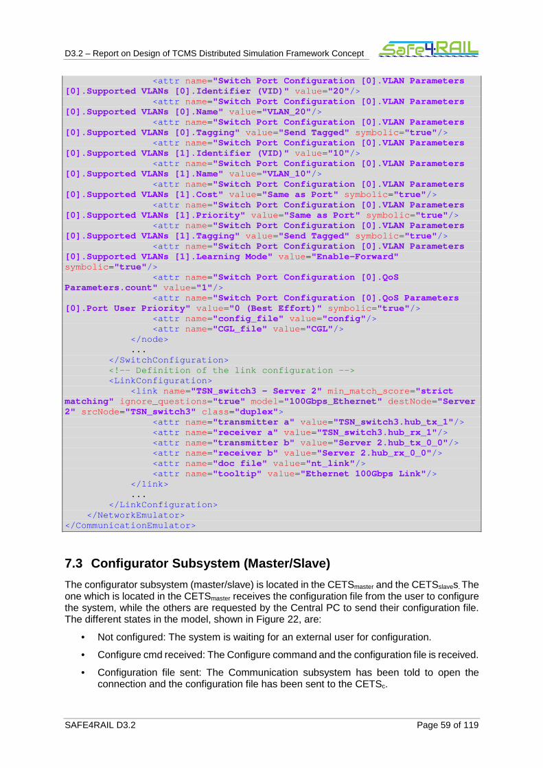
D3.2 – Report on Design of TCMS Distributed Simulation Framework Concept
SAFE4RAIL D3.2 Page 59 of 119
<attr name="Switch Port Configuration [0].VLAN Parameters [0].Supported VLANs [0].Identifier (VID)" value ="20"/> <attr name="Switch Port Configuration [0].VLAN Parameters [0].Supported VLANs [0].Name" value ="VLAN_20"/> <attr name="Switch Port Configuration [0].VLAN Parameters [0].Supported VLANs [0].Tagging" value ="Send Tagged" symbolic ="true"/> <attr name="Switch Port Configuration [0].VLAN Parameters [0].Supported VLANs [1].Identifier (VID)" value ="10"/> <attr name="Switch Port Configuration [0].VLAN Parameters [0].Supported VLANs [1].Name" value ="VLAN_10"/> <attr name="Switch Port Configuration [0].VLAN Parameters [0].Supported VLANs [1].Cost" value ="Same as Port" symbolic ="true"/> <attr name="Switch Port Configuration [0].VLAN Parameters [0].Supported VLANs [1].Priority" value ="Same as Port" symbolic ="true"/> <attr name="Switch Port Configuration [0].VLAN Parameters [0].Supported VLANs [1].Tagging" value ="Send Tagged" symbolic ="true"/> <attr name="Switch Port Configuration [0].VLAN Parameters [0].Supported VLANs [1].Learning Mode" value ="Enable-Forward" symbolic ="true"/> <attr name="Switch Port Configuration [0].QoS Parameters.count" value ="1"/> <attr name="Switch Port Configuration [0].QoS Parameters [0].Port User Priority" value ="0 (Best Effort)" symbolic ="true"/> <attr name="config_file" value ="config"/> <attr name="CGL_file" value ="CGL"/> </node> ... </SwitchConfiguration> <!-- Definition of the link configuration --> <LinkConfiguration> <link name="TSN_switch3 - Server 2" min_match_score ="strict matching" ignore_questions ="true" model ="100Gbps_Ethernet" destNode ="Server 2" srcNode ="TSN_switch3" class ="duplex"> <attr name="transmitter a" value ="TSN_switch3.hub_tx_1"/> <attr name="receiver a" value ="TSN_switch3.hub_rx_1"/> <attr name="transmitter b" value ="Server 2.hub_tx_0_0"/> <attr name="receiver b" value ="Server 2.hub_rx_0_0"/> <attr name="doc file" value ="nt_link"/> <attr name="tooltip" value ="Ethernet 100Gbps Link"/> </link> ... </LinkConfiguration> </NetworkEmulator> </CommunicationEmulator>
7.3 Configurator Subsystem (Master/Slave)
The configurator subsystem (master/slave) is located in the CETSmaster and the CETSslaves. The one which is located in the CETSmaster receives the configuration file from the user to configure the system, while the others are requested by the Central PC to send their configuration file. The different states in the model, shown in Figure 22, are:
• Not configured: The system is waiting for an external user for configuration.
• Configure cmd received: The Configure command and the configuration file is received.
• Configuration file sent: The Communication subsystem has been told to open the connection and the configuration file has been sent to the CETSc.

D3.2 – Report on Design of TCMS Distributed Simulation Framework Concept
SAFE4RAIL D3.2 Page 60 of 119
• Error reported: An error has been detected in the configuration. Errors could occur because another master has started the system or because the configuration file is not correct. This is reported to the UI subsystem.
• Configure file sent: The CETSc has requested the configuration file to the CETSslaves. This configuration files contains the information of the CESB manage by the CETSslave. The file has been sent to the CETSc.
• Controlled CESBs settled (master): The CETSc has informed the CETSmaster which CESBs is going to control.
• Controlled CESBs settled (slave): The CETSc has informed the CETSslave which CESBs is going to control.
• Configuration information sent to the CESB: The configuration information has been sent to the CESBs associated to the CETSslave.
• Configured and running: The whole system has been configured and it is running now, this new state has been reported to the UI subsystem.
• Fault injection reset: The fault reset command has been received and it has been routed to the corresponding CETSc.
• Fault injection started: The fault injection command has been received and it has been routed to the corresponding CETSc.
• Stop cmd received: The Stop command has been received and sent to the CETSc. The subsystem waits in this state system to be stopped and to report it.
• Reconfigure cmd received: The CETSmaster has received the reconfigure command and it has sent it to the CETSc.
• Error reported: An error because the configuration file is not correct has been detected. This has been reported to the UI subsystem.
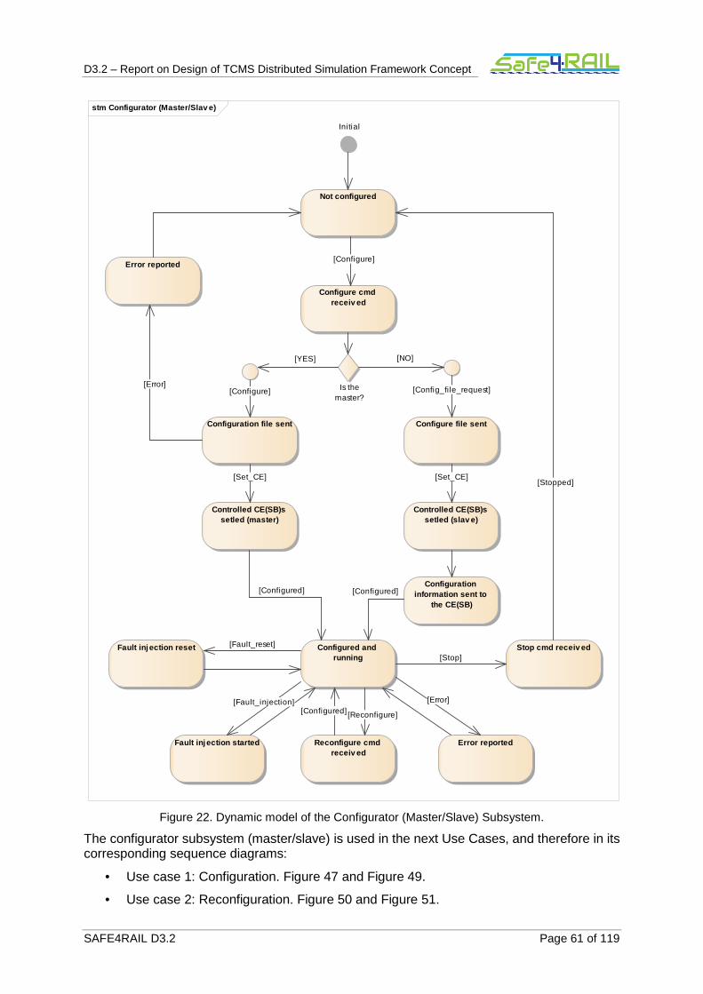
D3.2 – Report on Design of TCMS Distributed Simulation Framework Concept
SAFE4RAIL D3.2 Page 61 of 119
Figure 22. Dynamic model of the Configurator (Master/Slave) Subsystem.
The configurator subsystem (master/slave) is used in the next Use Cases, and therefore in its corresponding sequence diagrams:
• Use case 1: Configuration. Figure 47 and Figure 49.
• Use case 2: Reconfiguration. Figure 50 and Figure 51.
stm Configurator (Master/Slav e)
Initial
Not configured
Configure cmd receiv ed
Configuration file sent
Is themaster?
Configure file sent
Controlled CE(SB)s setled (master)
Configured and running
Error reported
Reconfigure cmd receiv ed
Stop cmd receiv ed
Error reported
Controlled CE(SB)s setled (slav e)
Configuration information sent to
the CE(SB)
Fault inj ection started
Fault inj ection reset [Fault_reset]
[Configure]
[Stop]
[Configured]
[Set_CE]
[Error]
[Error]
[Configured]
[Config_file_request]
[Configured]
[Stopped]
[Reconfigure]
[Fault_injection]
[Set_CE]
[NO]
[Configure]
[YES]
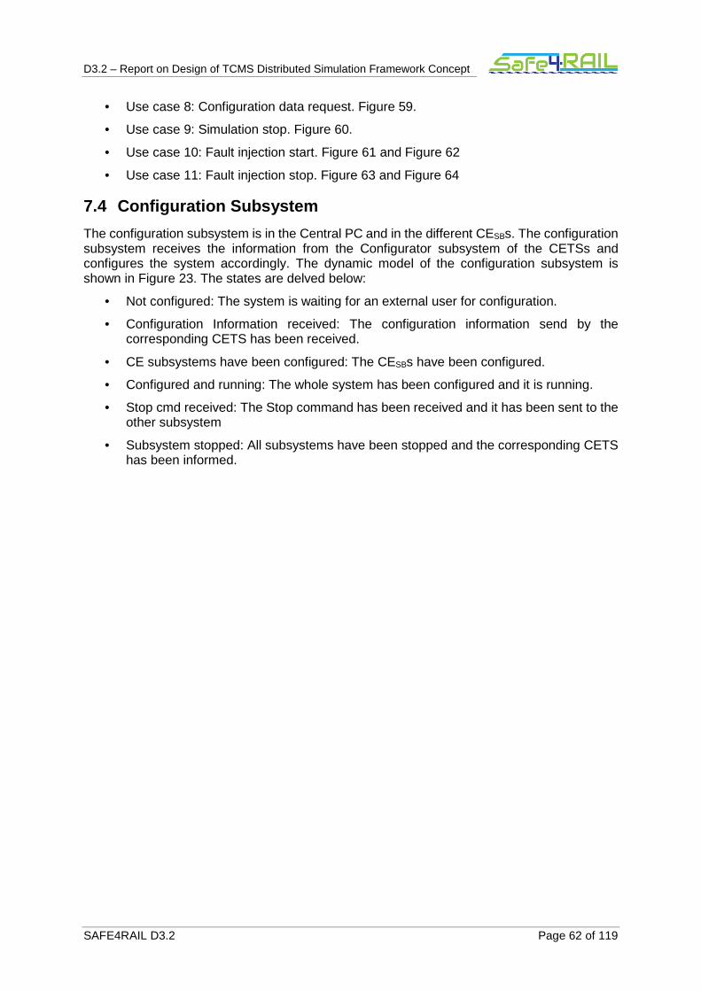
D3.2 – Report on Design of TCMS Distributed Simulation Framework Concept
SAFE4RAIL D3.2 Page 62 of 119
• Use case 8: Configuration data request. Figure 59.
• Use case 9: Simulation stop. Figure 60.
• Use case 10: Fault injection start. Figure 61 and Figure 62
• Use case 11: Fault injection stop. Figure 63 and Figure 64
7.4 Configuration Subsystem
The configuration subsystem is in the Central PC and in the different CESBs. The configuration subsystem receives the information from the Configurator subsystem of the CETSs and configures the system accordingly. The dynamic model of the configuration subsystem is shown in Figure 23. The states are delved below:
• Not configured: The system is waiting for an external user for configuration.
• Configuration Information received: The configuration information send by the corresponding CETS has been received.
• CE subsystems have been configured: The CESBs have been configured.
• Configured and running: The whole system has been configured and it is running.
• Stop cmd received: The Stop command has been received and it has been sent to the other subsystem
• Subsystem stopped: All subsystems have been stopped and the corresponding CETS has been informed.

D3.2 – Report on Design of TCMS Distributed Simulation Framework Concept
SAFE4RAIL D3.2 Page 63 of 119
Figure 23. Dynamic model of the Configuration Subsystem.
The configuration subsystem is used in the next Use Cases, and therefore in its corresponding sequence diagrams:
• Use case 1: Configuration (scenario 1). Figure 47.
• Use case 2: Reconfiguration (scenario 1). Figure 50.
• Use case 9: Simulation stop. Figure 60.
7.5 Monitoring Subsystem (Simulation Bridge)
The monitoring subsystem (simulation bridge) monitors the interactions in the CESB when it is told to do so. It sends the monitoring data to the user or storage it in a file which sends once the simulation is stopped. The different states in the model are:
• Not configured: The system is waiting for an external user for configuration.
• Configured and running: The whole system has been configured and it is waiting for an interaction.
• Interaction data sent: Interaction data has been sent to the corresponding CETS (the data is routed by the CETSc when sent to the CETSmaster).
• Data stored in the monitoring file: The interaction data has been stored into the monitoring file.
• Monitoring file sent: The monitoring file has been sent to the corresponding CETS (the data is routed by the CETSc when sent to the CETSmaster).
stm Configuration
Initial
Not configured
Configuration Information receiv ed
CE subsystems hav e been configured
Configured and running
Subsystem stopped
Stop cmd received
[Stop]
[Configure]
[Reconfigure]

D3.2 – Report on Design of TCMS Distributed Simulation Framework Concept
SAFE4RAIL D3.2 Page 64 of 119
Figure 24. Dynamic model of the Monitoring (Simulation Bridge) Subsystem.
The monitoring subsystem (simulation bridge) is used in the next Use Cases, and therefore in its corresponding sequence diagrams:
• Use case 6: Monitoring/measurements start. Figure 55 and Figure 56.
• Use case 7: Monitoring/measurements stop. Figure 57 and Figure 58.
• Use case 9: Simulation stop. Figure 60.
7.6 Monitoring Subsystem (Central)
The monitoring subsystem (central) routes the commands and the monitoring data between the CETSmaster and the different CESBs in the simulation. The different states in the model are:
• Not configured: The system is waiting for an external user to configure it.
• Configured and running: The whole system has been configured and it is running now.
• Command sent to the corresponding CESB: The CETSmaster monitoring commands has been routed to the corresponding CESB.
• Data sent to the CETSmaster: The CESB monitoring commands has been routed to the CETSmaster.
stm Monitoring (Simulation Bridge)
Initial
Not configured
Configured and running
Interaction data sent
Monitoring file sent
Store datain file?
Data stored in the monitoring file
Has amonitoring
fi le?
[Stop]
[Monitoring_stop]
[Monitoring_start]
[Yes]
[No]
[Interaction_produced |Interaction_subscribers]
[Stop]
[No]
[Yes]
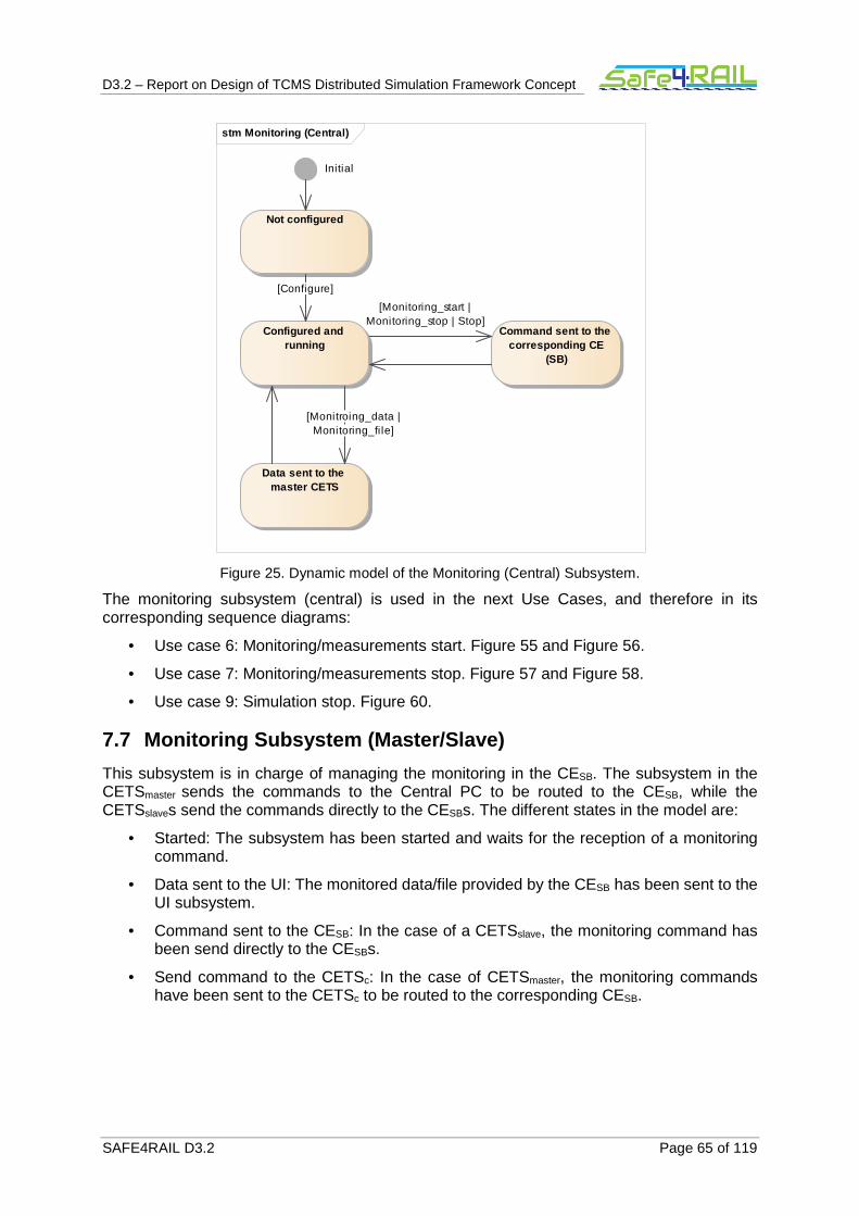
D3.2 – Report on Design of TCMS Distributed Simulation Framework Concept
SAFE4RAIL D3.2 Page 65 of 119
Figure 25. Dynamic model of the Monitoring (Central) Subsystem.
The monitoring subsystem (central) is used in the next Use Cases, and therefore in its corresponding sequence diagrams:
• Use case 6: Monitoring/measurements start. Figure 55 and Figure 56.
• Use case 7: Monitoring/measurements stop. Figure 57 and Figure 58.
• Use case 9: Simulation stop. Figure 60.
7.7 Monitoring Subsystem (Master/Slave)
This subsystem is in charge of managing the monitoring in the CESB. The subsystem in the CETSmaster sends the commands to the Central PC to be routed to the CESB, while the CETSslaves send the commands directly to the CESBs. The different states in the model are:
• Started: The subsystem has been started and waits for the reception of a monitoring command.
• Data sent to the UI: The monitored data/file provided by the CESB has been sent to the UI subsystem.
• Command sent to the CESB: In the case of a CETSslave, the monitoring command has been send directly to the CESBs.
• Send command to the CETSc: In the case of CETSmaster, the monitoring commands have been sent to the CETSc to be routed to the corresponding CESB.
stm Monitoring (Central)
Configured and running
Initial
Data sent to the master CETS
Command sent to the corresponding CE
(SB)
Not configured
[Configure]
[Monitroing_data |Monitoring_fi le]
[Monitoring_start |Monitoring_stop | Stop]
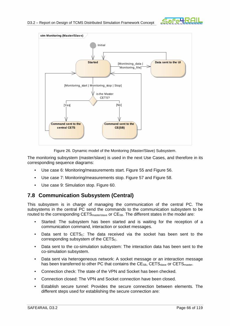
D3.2 – Report on Design of TCMS Distributed Simulation Framework Concept
SAFE4RAIL D3.2 Page 66 of 119
Figure 26. Dynamic model of the Monitoring (Master/Slave) Subsystem.
The monitoring subsystem (master/slave) is used in the next Use Cases, and therefore in its corresponding sequence diagrams:
• Use case 6: Monitoring/measurements start. Figure 55 and Figure 56.
• Use case 7: Monitoring/measurements stop. Figure 57 and Figure 58.
• Use case 9: Simulation stop. Figure 60.
7.8 Communication Subsystem (Central)
This subsystem is in charge of managing the communication of the central PC. The subsystems in the central PC send the commands to the communication subsystem to be routed to the corresponding CETSmaster/slave or CESB. The different states in the model are:
• Started: The subsystem has been started and is waiting for the reception of a communication command, interaction or socket messages.
• Data sent to CETSC: The data received via the socket has been sent to the corresponding subsystem of the CETSC.
• Data sent to the co-simulation subsystem: The interaction data has been sent to the co-simulation subsystem.
• Data sent via heterogeneous network: A socket message or an interaction message has been transferred to other PC that contains the CESB, CETSslave or CETSmaster.
• Connection check: The state of the VPN and Socket has been checked.
• Connection closed: The VPN and Socket connection have been closed.
• Establish secure tunnel: Provides the secure connection between elements. The different steps used for establishing the secure connection are:
stm Monitoring (Master/Slav e)
Initial
Started
Command sent to the central CETS
Command sent to the CE(SB)
is the MasterCETS?
Data sent to the UI[Monitroing_data |Monitoring_fi le]
[Monitoring_start | Monitoring_stop | Stop]
[Yes] [No]

D3.2 – Report on Design of TCMS Distributed Simulation Framework Concept
SAFE4RAIL D3.2 Page 67 of 119
o Request_connection message sent: A request connection message has been sent to the CESB and the CETSslave.
o Client_hello message received: The client_hello message that contains the SSL version, cipher settings and session-specific data has been received.
o Server_hello message sent: The cipher setting, session-specific data, server's certificate including public key (PK) have been sent to the CESB or CETSmaster/slave with whom the secure channel has been established.
o Cipher message received: The message containing the generated cipher has been received.
o Pre-master secret decrypted: The pre-master secret transferred in the cipher message has been decrypted.
o Session key generated: The session key based on the master secret has been generated.
o Acknowledge message sent: The acknowledge message has been sent to the CESB or CETSmaster/slave with the Encryption/Session key.
o Acknowledge message received and check: The acknowledge message has been received and the Encryption/Session key has been checked.
o Socket connection created: A socket connection with the communication subsystem of the CESB, CETSmaster or CETSslave has been created.
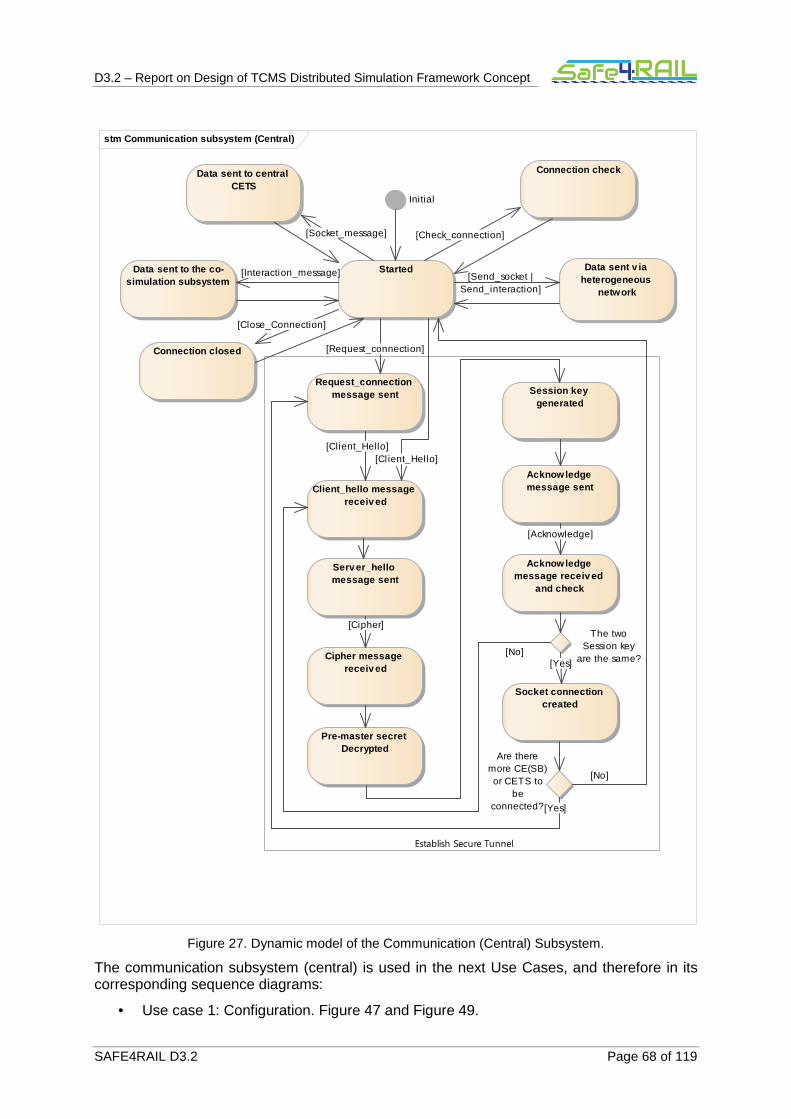
D3.2 – Report on Design of TCMS Distributed Simulation Framework Concept
SAFE4RAIL D3.2 Page 68 of 119
Figure 27. Dynamic model of the Communication (Central) Subsystem.
The communication subsystem (central) is used in the next Use Cases, and therefore in its corresponding sequence diagrams:
• Use case 1: Configuration. Figure 47 and Figure 49.
stm Communication subsystem (Central)
Initial
Started
Request_connection message sent
Connection checkData sent to central CETS
Data sent v ia heterogeneous
network
Data sent to the co-simulation subsystem
Connection closed
Client_hello message received
Cipher message received
Pre-master secret Decrypted
Session key generated
Acknow ledge message sent
Acknow ledge message received
and check
The twoSession key
are the same?
Are theremore CE(SB)or CETS to
beconnected?
Socket connection created
Establish Secure Tunnel
Server_hello message sent
[Interaction_message]
[No]
[Request_connection]
[Yes]
[Acknowledge]
[Yes]
[Client_Hello][Cl ient_Hello]
[Close_Connection]
[Check_connection]
[Cipher]
[No]
[Socket_message]
[Send_socket |Send_interaction]

D3.2 – Report on Design of TCMS Distributed Simulation Framework Concept
SAFE4RAIL D3.2 Page 69 of 119
• Use case 2: Reconfiguration. Figure 50 and Figure 51.
• Use case 3: SFTS commands. Figure 52.
• Use case 4: Ethernet interaction. Figure 53.
• Use case 5: I/O interaction. Figure 54.
• Use case 6: Monitoring/measurements start. Figure 55 and Figure 56.
• Use case 7: Monitoring/measurements stop. Figure 57 and Figure 58.
• Use case 8: Configuration data request. Figure 59.
• Use case 9: Simulation stop. Figure 60.
• Use case 10: Fault injection start. Figure 61
• Use case 11: Fault injection stop. Figure 63
7.9 Communication Subsystem (Master/Slave, Simulati on Bridge)
This subsystem is in charge of managing the communication of the CESTmaster/slave and CESB. The subsystems in the CETSmaster/slave and CESB route all their communications using the communication subsystem.
The different states in the model are:
• Started: The subsystem has been started and is waiting for the reception of a communication command, interaction or socket messages.
• Data sent to configuration/monitoring subsystem: The data received via the socket has been send to the configuration or monitoring subsystem.
• Data sent to the co-simulation subsystem: The interaction data has been sent to the co-simulation subsystem.
• Data sent via heterogeneous network: A socket message or an interaction message has been transferred to the central PC or the CETSslave.
• Connection check: The state of the VPN and Socket has been check.
• Connection closed: The VPN and Socket connection have been closed.
• Establish secure tunnel: Provides the secure connection between elements. The different steps used for establishing the secure connection are:
o Client_hello message sent: The message containing the SSL version, cipher settings and session-specific data has been sent to the central PC.
o Server_hello message received: The server VPN information regarding the cipher setting, session-specific data and server's certificate including public key (PK) have been received via the server_hello message.
o Server's certificate authenticated: The certificate of the central PC has been checked.
o Pre-master secret created: The pre-master secret key for the communication has been created.
o Cipher generated: The pre-master secret key has been created and generated.
o Cipher message sent: The cipher has been sent to the central PC.
o Session key generated: The session key based on the master secret has been generated.

D3.2 – Report on Design of TCMS Distributed Simulation Framework Concept
SAFE4RAIL D3.2 Page 70 of 119
o Acknowledge message sent: The acknowledge message containing the session key has been sent to the central PC.
o Acknowledge message received: The acknowledge message has been received and the Encryption/Session key has been checked.
o Socket connected: The subsystem has created a socket connection with the Central PC. In the case of CETSslaves and CESBs controlled by a CETSslave the corresponding socket connections (which connect both elements) have also been generated.

D3.2 – Report on Design of TCMS Distributed Simulation Framework Concept
SAFE4RAIL D3.2 Page 71 of 119
Figure 28. Dynamic model of the Communication (Master/Slave, Simulation Bridge) Subsystem.
The communication subsystem (master/slave, simulation bridge) is used in the next Use Cases, and therefore in its corresponding sequence diagrams:
• Use case 1: Configuration. Figure 47 and Figure 49.
• Use case 2: Reconfiguration. Figure 50 and Figure 51.
• Use case 3: SFTS commands. Figure 52.
• Use case 4: Ethernet interaction. Figure 53.
• Use case 5: I/O interaction. Figure 54.
stm Communication subsystem (distributed)
Initial
Started
Connection checkData sent to configuration/monitoring
subsystem
Data sent v ia heterogeneous
network
Data sent to the co-simulation subsystem
Connection closed
Send client_hello message
Serv er_hello message receiv ed
Serv er's certificate authenticated
Pre-master secret created
Cipher generated
Cipher message sent
Session key generated
Acknowledge message sent
Acknowledge message receiv ed
The two Sessionkey are the
same?
Socket connected
Establish Secure Tunnel
[No]
[Socket_message]
[Interaction_message]
[Acknowledge]
[Server_Hello]
[Open_Connection |Request_Connection]
[Close_Connection]
[Yes]
[Check_connection]
[Send_socket |Send_interaction]
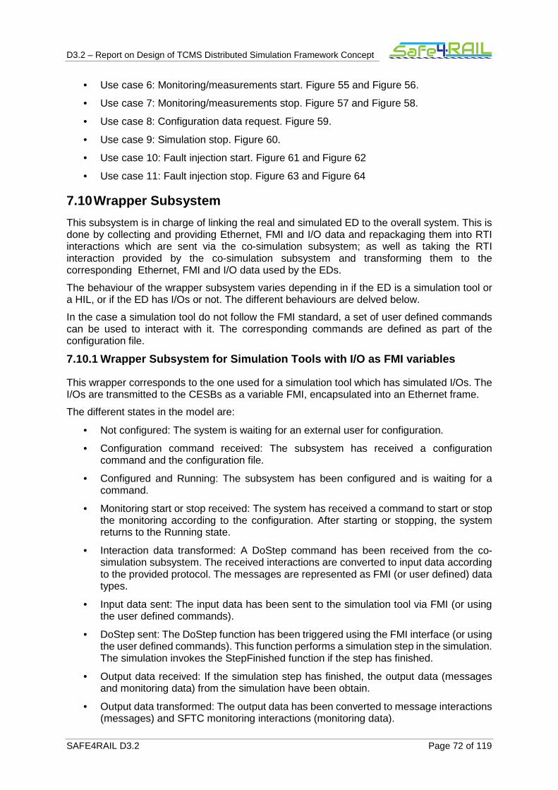
D3.2 – Report on Design of TCMS Distributed Simulation Framework Concept
SAFE4RAIL D3.2 Page 72 of 119
• Use case 6: Monitoring/measurements start. Figure 55 and Figure 56.
• Use case 7: Monitoring/measurements stop. Figure 57 and Figure 58.
• Use case 8: Configuration data request. Figure 59.
• Use case 9: Simulation stop. Figure 60.
• Use case 10: Fault injection start. Figure 61 and Figure 62
• Use case 11: Fault injection stop. Figure 63 and Figure 64
7.10 Wrapper Subsystem
This subsystem is in charge of linking the real and simulated ED to the overall system. This is done by collecting and providing Ethernet, FMI and I/O data and repackaging them into RTI interactions which are sent via the co-simulation subsystem; as well as taking the RTI interaction provided by the co-simulation subsystem and transforming them to the corresponding Ethernet, FMI and I/O data used by the EDs.
The behaviour of the wrapper subsystem varies depending in if the ED is a simulation tool or a HIL, or if the ED has I/Os or not. The different behaviours are delved below.
In the case a simulation tool do not follow the FMI standard, a set of user defined commands can be used to interact with it. The corresponding commands are defined as part of the configuration file.
7.10.1 Wrapper Subsystem for Simulation Tools with I/O as FMI variables
This wrapper corresponds to the one used for a simulation tool which has simulated I/Os. The I/Os are transmitted to the CESBs as a variable FMI, encapsulated into an Ethernet frame.
The different states in the model are:
• Not configured: The system is waiting for an external user for configuration.
• Configuration command received: The subsystem has received a configuration command and the configuration file.
• Configured and Running: The subsystem has been configured and is waiting for a command.
• Monitoring start or stop received: The system has received a command to start or stop the monitoring according to the configuration. After starting or stopping, the system returns to the Running state.
• Interaction data transformed: A DoStep command has been received from the co-simulation subsystem. The received interactions are converted to input data according to the provided protocol. The messages are represented as FMI (or user defined) data types.
• Input data sent: The input data has been sent to the simulation tool via FMI (or using the user defined commands).
• DoStep sent: The DoStep function has been triggered using the FMI interface (or using the user defined commands). This function performs a simulation step in the simulation. The simulation invokes the StepFinished function if the step has finished.
• Output data received: If the simulation step has finished, the output data (messages and monitoring data) from the simulation have been obtain.
• Output data transformed: The output data has been converted to message interactions (messages) and SFTC monitoring interactions (monitoring data).
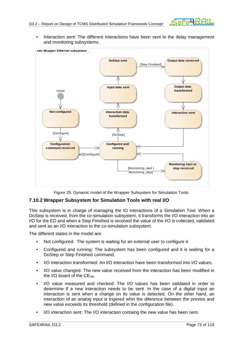
D3.2 – Report on Design of TCMS Distributed Simulation Framework Concept
SAFE4RAIL D3.2 Page 73 of 119
• Interaction sent: The different interactions have been sent to the delay management and monitoring subsystems.
Figure 29. Dynamic model of the Wrapper Subsystem for Simulation Tools.
7.10.2 Wrapper Subsystem for Simulation Tools with real I/O
This subsystem is in charge of managing the IO interactions of a Simulation Tool. When a DoStep is received, from the co-simulation subsystem, it transforms the I/O interaction into an I/O for the ED and when a Step Finished is received the value of the I/O is collected, validated and sent as an I/O interaction to the co-simulation subsystem.
The different states in the model are:
• Not configured: The system is waiting for an external user to configure it.
• Configured and running: The subsystem has been configured and it is waiting for a DoStep or Step Finished command.
• I/O interaction transformed: An I/O interaction have been transformed into I/O values.
• I/O value changed: The new value received from the interaction has been modified in the I/O board of the CESB.
• I/O value measured and checked: The I/O values has been validated in order to determine if a new interaction needs to be sent. In the case of a digital input an interaction is sent when a change on its value is detected. On the other hand, an interaction of an analog input is trigered whin the diference between the previos and new value exceeds its threshold (defined in the configuration file).
• I/O interaction sent: The I/O interaction containg the new value has been sent.
stm Wrapper Ethernet subsystem
Configured and running
Not configured
Initial
Configuration command receiv ed
Interaction data transformed
Input data sent
DoStep sent Output data receiv ed
Output data transformed
Interaction sent
Monitoring start or stop receiv ed[Monitoring_start |
Monitoring_stop]
[DoStep]
[Configure]
[Step Finished]
[Configure]

D3.2 – Report on Design of TCMS Distributed Simulation Framework Concept
SAFE4RAIL D3.2 Page 74 of 119
Figure 30. Dynamic model of the Wrapper Subsystem for Simulation Tools with I/O .
7.10.3 Wrapper Subsystem for HIL
This wrapper is used to connect a HIL to the CE. No I/Os inputs/outputs are supported, only Ethernet frames. Also, it is valid for simulation tools which do not support DoStep or StepFinished commands.
The different states in the model are:
• Not configured: The system is waiting for an external user for configuration.
• Configuration command received: The subsystem has received a configuration command and the configuration file.
• Configured and Running: The sub-system has been configured and waiting for a command.
• Ctrl CMD forwarded: The system has received a command to control the HIL device. The command has been forwarded and if it is executed successfully, the system returns to the Running state.
• Monitoring CMD received: The system has received a command to start or stop the monitoring according to the configuration. After starting or stopping, the system returns to the Running state.
• Interaction received: An interaction has been received from the fault-injection subsystem and converted into messages for the ED according to the provided protocol.
• Message forwarded to ED: The message has been sent to the ED via Ethernet.
stm Wrapper subsystem ST I/O
I/O v alue measured and checked
I/O interaction transformed
Configured and running
Not configured
Initial
I/O valueneeds to be
sent?
I/O interaction sent
I/O v alue changed[NO]
[YES]
[DoStep &Interaction_wrapper &
I/O]
[Configure]
[StepFinished]
D3.2 – Report on Design of TCMS Distributed Simulation Framework Concept
SAFE4RAIL D3.2 Page 75 of 119
• Ethernet message received: An Ethernet message from the ED has been received and converted into a related to message interactions and monitoring interactions.
• Interaction sent: The interaction has been sent to the co-simulation, delay management and mentoring subsystems.
Figure 31. Dynamic model of the Wrapper Subsystem for HIL.
7.10.4 Wrapper Subsystem for HIL with I/O
This subsystem is in charge of managing the IO interactions of a HIL ED. When an IO interaction is received, from the co-simulation subsystem, it is transformed into an I/O for the ED and when an I/O variation is detected the value is sent as an I/O interaction to the co-simulation subsystem. Also, it is valid for simulation tools which do not support DoStep or StepFinished commands.
The different states in the model are:
• Not configured: The system is waiting for an external user to configure it.
• Configured and running: The sub-system has been configured and it is waiting for an interaction or to reach the sampling time of an I/O.
• I/O interaction received: An I/O interaction has been received from the delay manager subsystem.
• I/O value changed: The new value received from the interaction has been modified in the I/O board of the CESB.
• I/O value measured and checked: The sampling time of an I/O has been reached and its value sampled. This sampling determines if a new interaction needs to be sent. In
stm Wrapper subsystem HIL
Interaction received
Message forwarded to ED
Ethernet message receiv ed
Interaction sent
Ctrl CMD forwarded
Configuration command receiv ed
Configured and running
Not configured
Initial
Monitoring CMD received
[Ethernet_frame]
[Ctrl CMD]
[Monitoring_start |Monitoring_stop][Configured]
[Configure]
[Interaction_wrapper]

D3.2 – Report on Design of TCMS Distributed Simulation Framework Concept
SAFE4RAIL D3.2 Page 76 of 119
the case of a digital input an interaction is sent when a change on its value is detected. On the other hand, an interaction of an analog input is trigered when the difference between the previous and the new value exceeds its threshold (defined in the configuration file).
• I/O interaction sent: The I/O interaction containg the new value has been sent.
Figure 32. Dynamic model of the Wrapper Subsystem for HIL with I/O.
7.11 Delay Manager Subsystem
7.11.1 Delay-Management concept
In hard real-time systems it is necessary to satisfy all deadlines since otherwise there might be catastrophic consequences. To test the behaviour of those systems it is therefore important to provide the required messages in time. Since the Internet introduces delays and jitter which is indeterministic, the end device connected to the simulation bridge might not receive the data it requires in time. The delay management subsystem manages the delays to provide the best possible accuracy of the simulation.
Common message types in embedded systems are Time-Triggered (TT), Rate-Constrained (RC) and Best-Effort (BE) messages. TT messages are fully temporally specified by period, offset and length. Time-triggered protocols may support multiple periods in the schedule and in each period an offset can be specified when the message needs to be sent.
RC messages have less constraints on the sending time than the TT. The messages have a defined maximum rate with which they may be generated. The minimum time between two instances of frame fi is (fi.rate)-1 (called Minimum Inter-arrival Time, MINT) but there is no upper bound defined. If a faulty sender injects messages with a higher rate, the messages are dropped to provide the correctness of the system.
stm Wrapper subsystem HIL I/O
I/O value measured and checked
I/O interaction receiv ed
Configured and running
Not configured
Initial
I/O valueneeds to be
sent?
I/O interaction sent
I/O v alue changed[NO]
[Samplingtime]
[Interaction_wrapper& I/O]
[YES]
[Configure]
D3.2 – Report on Design of TCMS Distributed Simulation Framework Concept
SAFE4RAIL D3.2 Page 77 of 119
Based on the temporal constraints, the delay management subsystem can determine the instant when the end device requires the reception of a message. For TT messages, the instant of time is defined by the message schedule while BE messages do not have any temporal bounds. Hence, BE messages are not estimated but forwarded when they arrive. If TT messages do not arrive in time, they are estimated.
In case of rate-constrained messages, determining the instant of reception is not possible with the parameters defined above since there is no upper bound and the messages are not necessarily sent. To handle the message type in the delay management, a Maximum Inter-arrival Time (MaxINT) and a Reception Probability are introduced. In combination with the MINT, MaxINT determines the time interval after the last reception in which the next RC frame instance should be received by the end device. If not, the delay management will inject an estimated RC frame if the reception probability fits.
The Delay-Management Subsystem continuously checks the bounds and decides if a message needs to be delivered to the end device. If the required message is received by the Co-Simulation Subsystem, it is forwarded to the device. Otherwise, the message is taken from the State-Estimation functionality if this system is enabled. In the latter case, the Simulation Bridge logs the estimated message, the real message as soon as it arrives and the time of injection so that the user can decide if the simulation results are appropriate. It is further possible to disable the State-Estimation functionality. Then the delay management determines the delay and signals the SFTS to stop the simulation if the delay is too large.
If the Simulation Bridge connects a real end device to the rest of the simulation, there are different time bases. The HLA realizing the communication and synchronization of the different end devices is based on a logical time while a real end device works with a real, physical time. Hence, there must be a synchronization mechanism between the simulation bridge and the end device.
In the Delay-Management Subsystem, the device's current physical time is stored as a real-time image. This image is updated periodically by using a time-stamp included into the messages sent from the end device. If the number of messages sent does not provide a sufficient synchronization granularity, the end device can further send explicit synchronization messages (e.g. using the IEEE 1588 standard). In between, the real-time image is updated based on the physical time of the node on which the Simulation Bridge is executed.
It shall also be possible to connect existing real end devices to the simulation bridge. Those devices may not include time-stamps or send explicit messages for synchronization. In this case and if JTAG is supported, the interface can be used to read the device’s internal state. If the end device does not provide any information which can be used, it is not possible to synchronize it with other end devices or simulation tools.
7.11.2 Delay-Management Model
The resulting different states in the subsystem model are:
• Wait for configuration: The system is waiting for an external user for configuration.
• Configuration command received: If the system received a configuration command and the configuration file is valid, the system and the simulation are configured in this state.
• Configured and Running with StateEstimation: If the configuration was successful and the state-estimation is enabled, the system changes to this state. It is running and waiting for a command
• Check Message Availability: As soon as the next instant for a message arrival is reached, the system checks if a message is available from the co-simulation subsystem for the related instant of time. The instants are stored in a list which is updated during the simulation execution to contain the correct times

D3.2 – Report on Design of TCMS Distributed Simulation Framework Concept
SAFE4RAIL D3.2 Page 78 of 119
• MSG from CoSimulation: If a message is available in the co-simulation subsystem, the system changes to this state.
• MSG from StateEstimation: If there is no message available from the co-simulation subsystem, the next message has to be estimated in this state.
• Provide MSG to Wrapper with StateEstimation: The received/estimated message is passed to the wrapper subsystem in this state. Afterwards, the system returns to the Running state.
• Get MSG from Wrapper: If the HIL device attempts to send a message, it sends the message via Ethernet to the wrapper. The wrapper forwards the message to the Delay-Management which changes to this state.
• Check Timestamp: The Delay-Management checks the time-stamp provided in the message and updates the real-time image of the end device’s physical time.
• Stop Simulation: There are two cases when the system changes to this state: (1) If the state-estimation is enabled and the time-stamp exceeds the maximum drift (∆max) between the time in the message (real-time in the HIL device) and the current logical time of the federation and (2) if the state-estimation is disabled and the input message is received after the maximum delay. In both cases the simulation has to be stopped.
• Provide MSG to CoSimulation and StateEstimation: If the state-estimation is enabled and the time-stamp is within the supported drift, the message is forwarded to the Co-Simulation subsystem and State-Estimation functionality to be sent to the other federates and to update the state in the State-Estimation. Afterwards, the system returns to the Running state.
• Configured and Running without StateEstimation: If the configuration was successful and the state-estimation is disabled, the system changes to this state. It is running and waiting for a command
• Provide MSG to Wrapper without StateEstimation: The message received before the maximum delay has passed is forwarded to the wrapper subsystem in this state. Afterwards, the system returns to the Running state.
• Provide MSG to CoSimulation: If the state-estimation is disabled and the time-stamp is within the supported drift, the message is forwarded to the CoSimulation subsystem to be sent to the other federates and to update the state in the StateEstimation. Afterwards, the system returns to the Running state.

D3.2 – Report on Design of TCMS Distributed Simulation Framework Concept
SAFE4RAIL D3.2 Page 79 of 119
Figure 33. Dynamic model of the Delay Manager Subsystem
7.11.3 State-Estimation Functionality
Providing the required input data for the end system even if the latencies introduced by the network are too high to transmit the messages in time is the purpose of the State-Estimation functionality. It estimates the future inputs based on the messages received during the simulation execution and an estimation model.
To estimate future inputs, the subsystem requires knowledge of the data available in the end device and the content of the messages received. Using this knowledge, the State-Estimation functionality can aggregate the state of the required inputs during the simulation execution. This state is called the Real State of the input. Based on it and the estimation model, the subsystem estimates the required inputs for instances when a message could not be delivered in time. Hence, the state prepared this way is called Estimated State.
During the simulation execution, the Delay-Management Subsystem provides all messages received to the State-Estimation functionality. Using the knowledge about its content, the message is analysed and the real state is updated even if the message arrives too late. The estimated state is always calculated based on the current real state using a model. Often statistical models or filters are used for the estimation such as Kalman, H∞ or particle filters.
The knowledge the State-Estimation functionality requires depends on the system which is simulated. Therefore, the system is designed as a black box. It uses the interface based on FMI which is defined in Table 3 and provided by the Delay-Management Subsystem. The
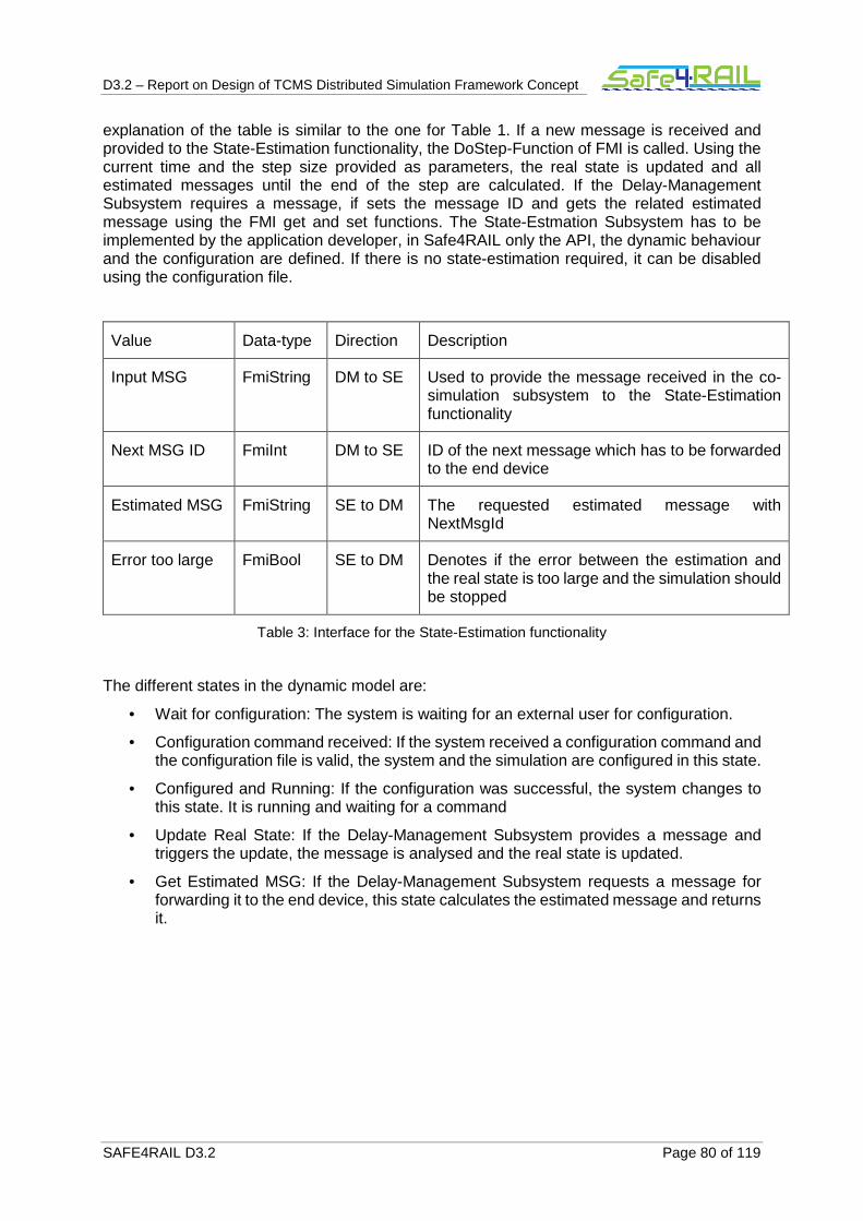
D3.2 – Report on Design of TCMS Distributed Simulation Framework Concept
SAFE4RAIL D3.2 Page 80 of 119
explanation of the table is similar to the one for Table 1. If a new message is received and provided to the State-Estimation functionality, the DoStep-Function of FMI is called. Using the current time and the step size provided as parameters, the real state is updated and all estimated messages until the end of the step are calculated. If the Delay-Management Subsystem requires a message, if sets the message ID and gets the related estimated message using the FMI get and set functions. The State-Estmation Subsystem has to be implemented by the application developer, in Safe4RAIL only the API, the dynamic behaviour and the configuration are defined. If there is no state-estimation required, it can be disabled using the configuration file.
Value Data-type Direction Description
Input MSG FmiString DM to SE Used to provide the message received in the co-simulation subsystem to the State-Estimation functionality
Next MSG ID FmiInt DM to SE ID of the next message which has to be forwarded to the end device
Estimated MSG FmiString SE to DM The requested estimated message with NextMsgId
Error too large FmiBool SE to DM Denotes if the error between the estimation and the real state is too large and the simulation should be stopped
Table 3: Interface for the State-Estimation functionality
The different states in the dynamic model are:
• Wait for configuration: The system is waiting for an external user for configuration.
• Configuration command received: If the system received a configuration command and the configuration file is valid, the system and the simulation are configured in this state.
• Configured and Running: If the configuration was successful, the system changes to this state. It is running and waiting for a command
• Update Real State: If the Delay-Management Subsystem provides a message and triggers the update, the message is analysed and the real state is updated.
• Get Estimated MSG: If the Delay-Management Subsystem requests a message for forwarding it to the end device, this state calculates the estimated message and returns it.
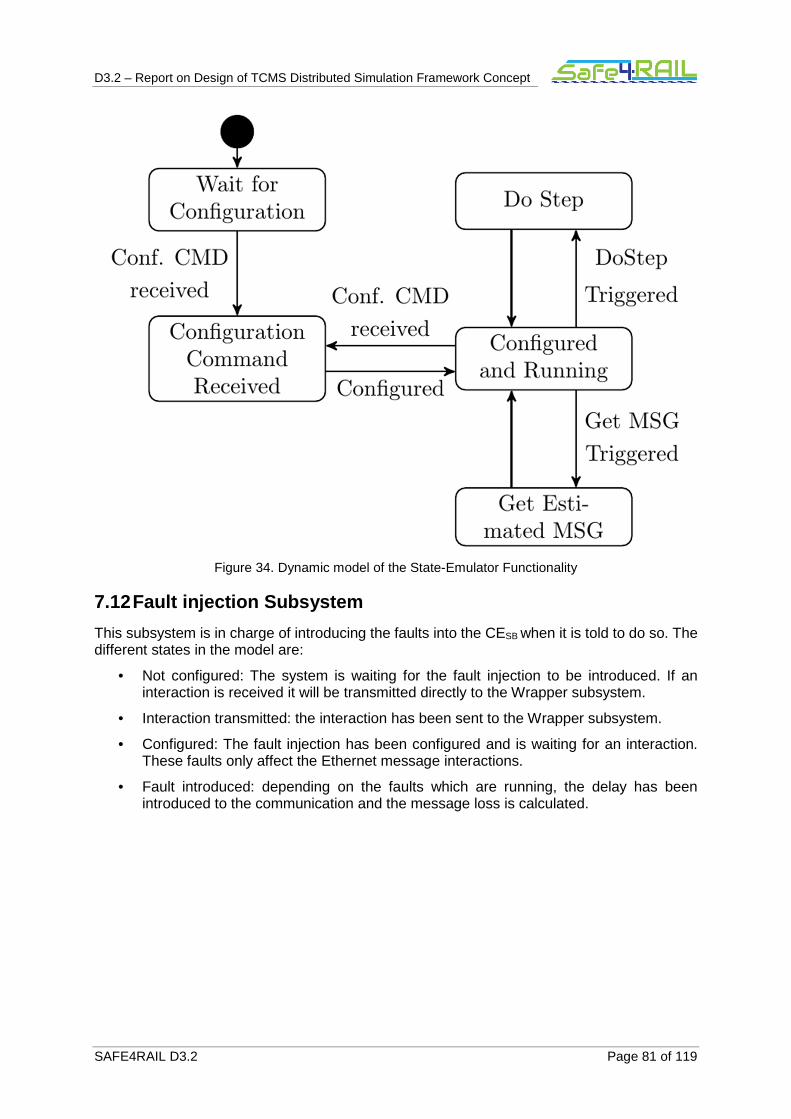
D3.2 – Report on Design of TCMS Distributed Simulation Framework Concept
SAFE4RAIL D3.2 Page 81 of 119
Figure 34. Dynamic model of the State-Emulator Functionality
7.12 Fault injection Subsystem
This subsystem is in charge of introducing the faults into the CESB when it is told to do so. The different states in the model are:
• Not configured: The system is waiting for the fault injection to be introduced. If an interaction is received it will be transmitted directly to the Wrapper subsystem.
• Interaction transmitted: the interaction has been sent to the Wrapper subsystem.
• Configured: The fault injection has been configured and is waiting for an interaction. These faults only affect the Ethernet message interactions.
• Fault introduced: depending on the faults which are running, the delay has been introduced to the communication and the message loss is calculated.

D3.2 – Report on Design of TCMS Distributed Simulation Framework Concept
SAFE4RAIL D3.2 Page 82 of 119
Figure 35. Dynamic model of the Fault injection Subsystem
The fault injection subsystem is used in the next Use Cases, and therefore in its corresponding sequence diagrams:
• Use case 3: SFTS commands. Figure 52.
• Use case 4: Ethernet interaction. Figure 53.
• Use case 5: I/O interaction. Figure 54.
• Use case 9: Simulation stop. Figure 60.
• Use case 10: Fault injection start. Figure 61 and Figure 62
• Use case 11: Fault injection stop. Figure 63 and Figure 64
7.13 Co-Simulation Subsystem
The co-simulation subsystem is based on the HLA standard for co-simulation. To use the HLA services, several steps are required to be performed. Those steps are collected into multiple high level states depicted in Figure 36. The co-simulation subsystem synchronizes all devices in the co-simulation framework to a common, (logical) simulation time.
• Not configured: The system is waiting to an external user for configure itself.
• Connect and init: Performs the connection to the RTI, as well as the initial configuration of the federate and the definition of the objects and interactions used by the subsystem. This state is only entered when the framework is started.
stm Fault injection subsystem
Initial
Not configured
Configured
Interaction transmitted
Fault introduced
The message needs tobe sent?
Interaction transmitted
Is anEthernetmessage
interaction?
Other type offaults being
injected?
[Interaction_subscribers]
[NO] [YES]
[Interaction_subscribers]
[NO]
[YES]
[YES]
[fault_injection]
[stop]
[fault_reset]
[NO]
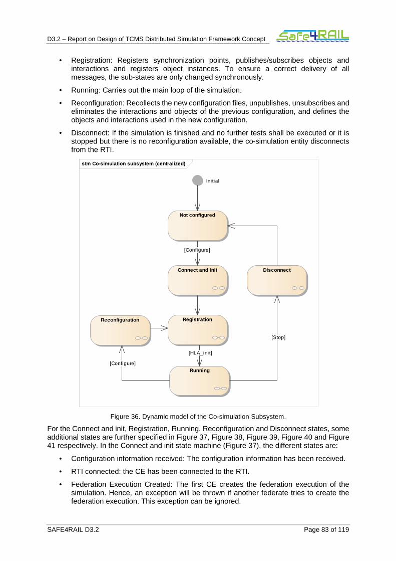
D3.2 – Report on Design of TCMS Distributed Simulation Framework Concept
SAFE4RAIL D3.2 Page 83 of 119
• Registration: Registers synchronization points, publishes/subscribes objects and interactions and registers object instances. To ensure a correct delivery of all messages, the sub-states are only changed synchronously.
• Running: Carries out the main loop of the simulation.
• Reconfiguration: Recollects the new configuration files, unpublishes, unsubscribes and eliminates the interactions and objects of the previous configuration, and defines the objects and interactions used in the new configuration.
• Disconnect: If the simulation is finished and no further tests shall be executed or it is stopped but there is no reconfiguration available, the co-simulation entity disconnects from the RTI.
Figure 36. Dynamic model of the Co-simulation Subsystem.
For the Connect and init, Registration, Running, Reconfiguration and Disconnect states, some additional states are further specified in Figure 37, Figure 38, Figure 39, Figure 40 and Figure 41 respectively. In the Connect and init state machine (Figure 37), the different states are:
• Configuration information received: The configuration information has been received.
• RTI connected: the CE has been connected to the RTI.
• Federation Execution Created: The first CE creates the federation execution of the simulation. Hence, an exception will be thrown if another federate tries to create the federation execution. This exception can be ignored.
stm Co-simulation subsystem (centralized)
Initial
Not configured
Connect and Init
RegistrationReconfiguration
Disconnect
Running
[Stop]
[HLA_init]
[Configure]
[Configure]
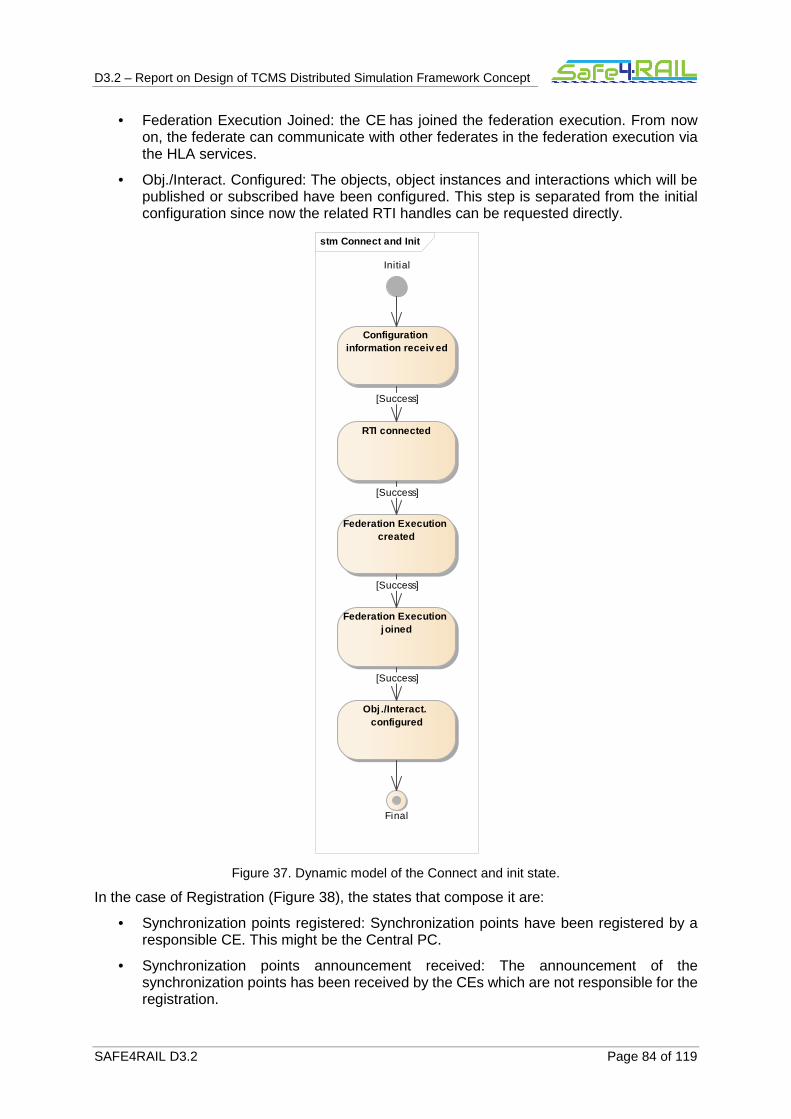
D3.2 – Report on Design of TCMS Distributed Simulation Framework Concept
SAFE4RAIL D3.2 Page 84 of 119
• Federation Execution Joined: the CE has joined the federation execution. From now on, the federate can communicate with other federates in the federation execution via the HLA services.
• Obj./Interact. Configured: The objects, object instances and interactions which will be published or subscribed have been configured. This step is separated from the initial configuration since now the related RTI handles can be requested directly.
Figure 37. Dynamic model of the Connect and init state.
In the case of Registration (Figure 38), the states that compose it are:
• Synchronization points registered: Synchronization points have been registered by a responsible CE. This might be the Central PC.
• Synchronization points announcement received: The announcement of the synchronization points has been received by the CEs which are not responsible for the registration.
stm Connect and Init
Configuration information receiv ed
RTI connected
Federation Execution created
Federation Execution joined
Obj ./Interact. configured
Initial
Final
[Success]
[Success]
[Success]
[Success]
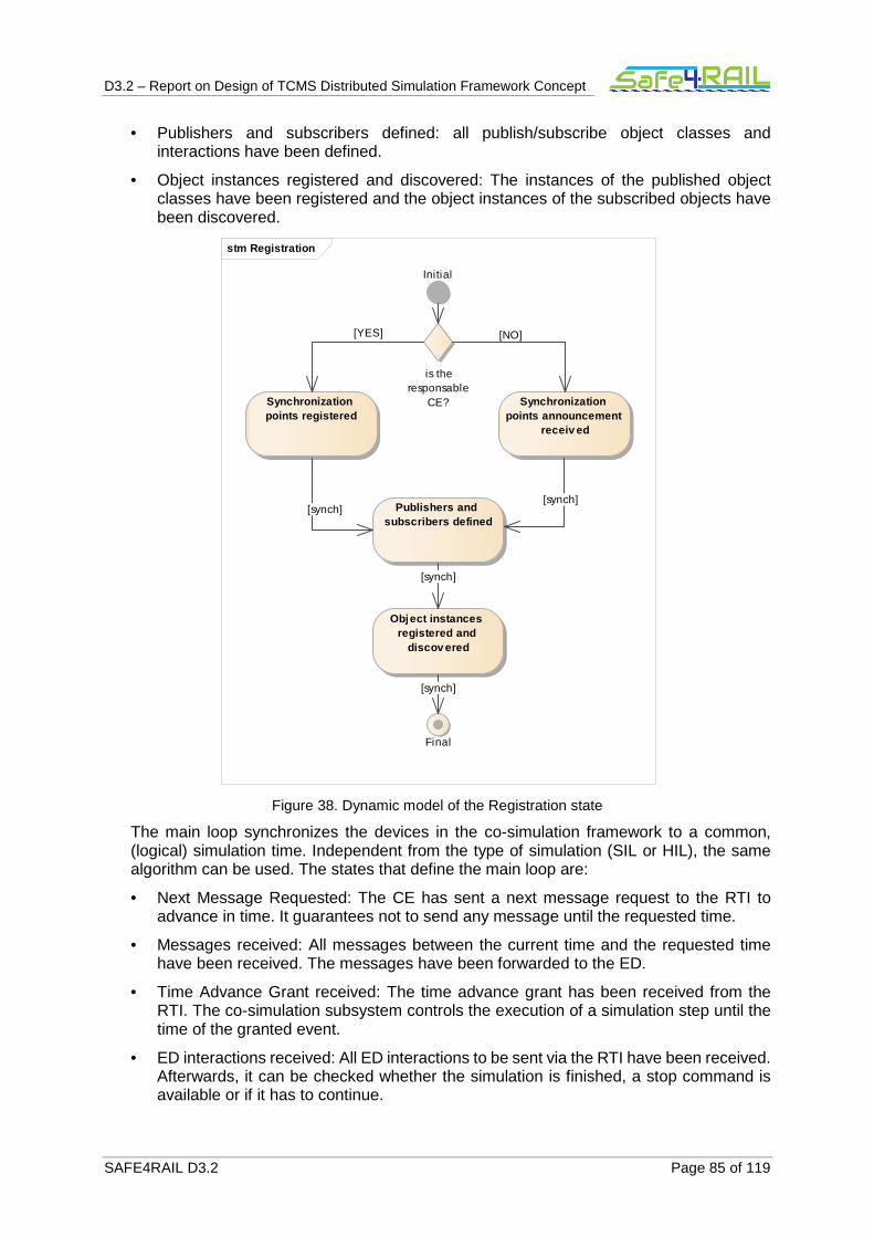
D3.2 – Report on Design of TCMS Distributed Simulation Framework Concept
SAFE4RAIL D3.2 Page 85 of 119
• Publishers and subscribers defined: all publish/subscribe object classes and interactions have been defined.
• Object instances registered and discovered: The instances of the published object classes have been registered and the object instances of the subscribed objects have been discovered.
Figure 38. Dynamic model of the Registration state
The main loop synchronizes the devices in the co-simulation framework to a common, (logical) simulation time. Independent from the type of simulation (SIL or HIL), the same algorithm can be used. The states that define the main loop are:
• Next Message Requested: The CE has sent a next message request to the RTI to advance in time. It guarantees not to send any message until the requested time.
• Messages received: All messages between the current time and the requested time have been received. The messages have been forwarded to the ED.
• Time Advance Grant received: The time advance grant has been received from the RTI. The co-simulation subsystem controls the execution of a simulation step until the time of the granted event.
• ED interactions received: All ED interactions to be sent via the RTI have been received. Afterwards, it can be checked whether the simulation is finished, a stop command is available or if it has to continue.
stm Registration
Synchronization points registered
Publishers and subscribers defined
Object instances registered and
discov ered
Initial
Final
is theresponsable
CE? Synchronization points announcement
receiv ed
[NO][YES]
[synch]
[synch]
[synch]
[synch]
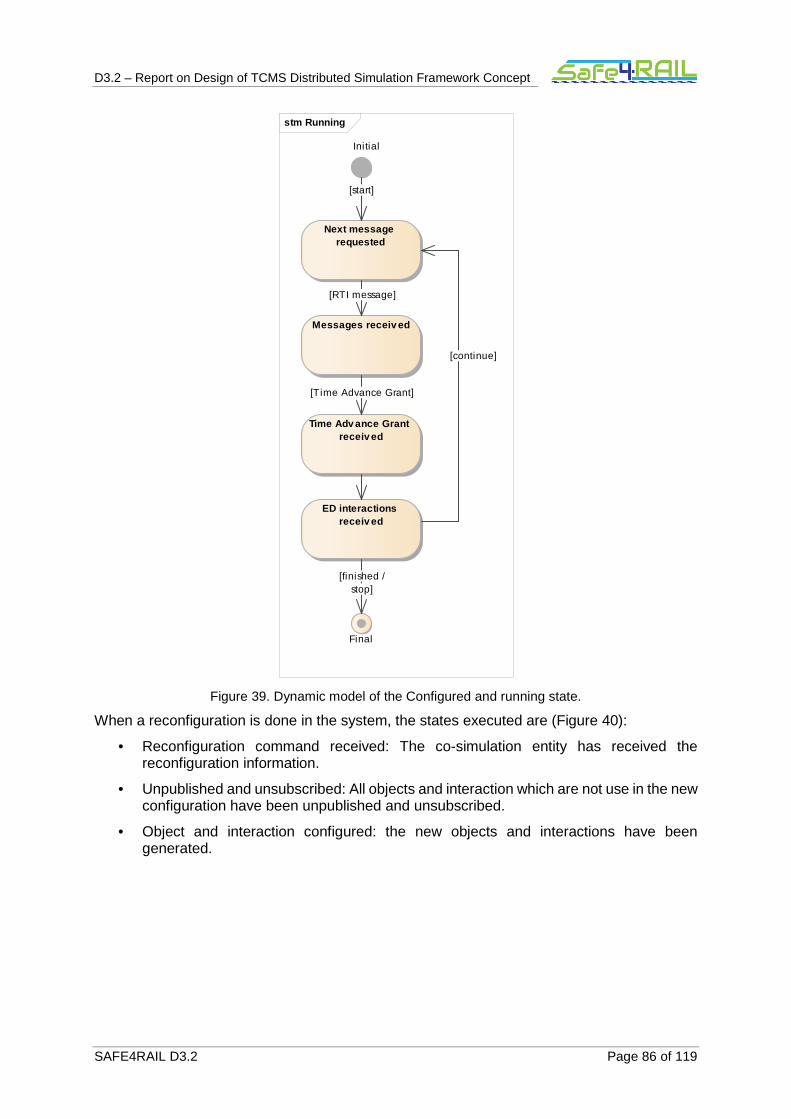
D3.2 – Report on Design of TCMS Distributed Simulation Framework Concept
SAFE4RAIL D3.2 Page 86 of 119
Figure 39. Dynamic model of the Configured and running state.
When a reconfiguration is done in the system, the states executed are (Figure 40):
• Reconfiguration command received: The co-simulation entity has received the reconfiguration information.
• Unpublished and unsubscribed: All objects and interaction which are not use in the new configuration have been unpublished and unsubscribed.
• Object and interaction configured: the new objects and interactions have been generated.
stm Running
Next message requested
Messages receiv ed
Time Adv ance Grant receiv ed
ED interactions receiv ed
Initial
Final
[Time Advance Grant]
[RTI message]
[finished /stop]
[continue]
[start]

D3.2 – Report on Design of TCMS Distributed Simulation Framework Concept
SAFE4RAIL D3.2 Page 87 of 119
Figure 40. Dynamic model of the Reconfiguration state.
Finally, when the stop command is received, the system follows the dynamic model shown in Figure 41, whose states are:
• Unpublished and unsubscribed: All objects and interactions have been unpublished and unsubscribed.
• Federation execution resigned: the CE has been disconnected from the federation execution. The usage of HLA services is not possible anymore unless a configure command is sent.
• Federation execution destroyed: the federation execution has been destroyed by the last CE. All earlier attempts to destroy the execution have triggered exceptions which can be ignored.
stm Reconfiguration
Initial
Reconfiguration command reciev ed
Unpublished and unsubscribed
Obj ./Interact. configured
Final
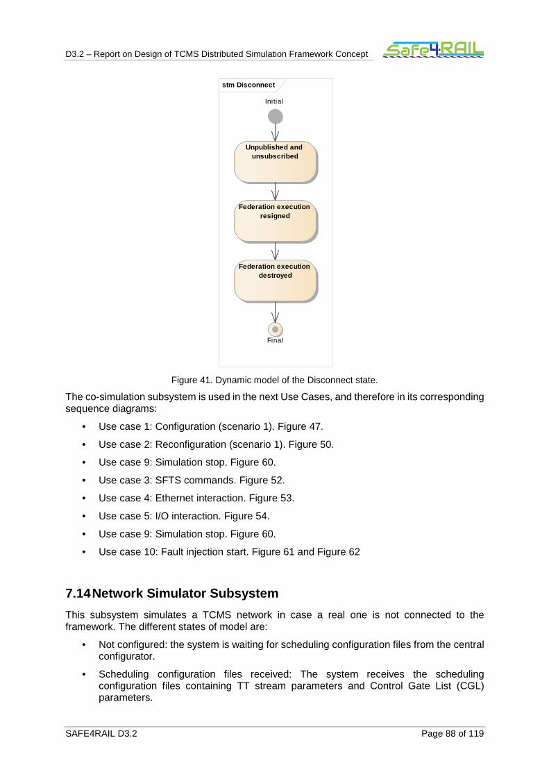
D3.2 – Report on Design of TCMS Distributed Simulation Framework Concept
SAFE4RAIL D3.2 Page 88 of 119
Figure 41. Dynamic model of the Disconnect state.
The co-simulation subsystem is used in the next Use Cases, and therefore in its corresponding sequence diagrams:
• Use case 1: Configuration (scenario 1). Figure 47.
• Use case 2: Reconfiguration (scenario 1). Figure 50.
• Use case 9: Simulation stop. Figure 60.
• Use case 3: SFTS commands. Figure 52.
• Use case 4: Ethernet interaction. Figure 53.
• Use case 5: I/O interaction. Figure 54.
• Use case 9: Simulation stop. Figure 60.
• Use case 10: Fault injection start. Figure 61 and Figure 62
7.14 Network Simulator Subsystem
This subsystem simulates a TCMS network in case a real one is not connected to the framework. The different states of model are:
• Not configured: the system is waiting for scheduling configuration files from the central configurator.
• Scheduling configuration files received: The system receives the scheduling configuration files containing TT stream parameters and Control Gate List (CGL) parameters.
stm Disconnect
Initial
Unpublished and unsubscribed
Federation execution resigned
Federation execution destroyed
Final

D3.2 – Report on Design of TCMS Distributed Simulation Framework Concept
SAFE4RAIL D3.2 Page 89 of 119
• Configured and running: The network simulator subsystems configured using the configuration files and ready to receive packets from the directly connected subsystems.
• Switch and port identified: the destination switch in the network simulator and the destination port are identified, and the message is sent to this port.
• Switch state machine: the switch processes the message. This state machine is delved below.
• Packet sent to the CESB: the packet is sent to the CESB to be sent to the ED.

D3.2 – Report on Design of TCMS Distributed Simulation Framework Concept
SAFE4RAIL D3.2 Page 90 of 119
Figure 42 Dynamic model of the Network Simulator Subsystem.
The dynamic model of the Switch machine state is shown in Figure 43, all the states are explained below:
stm Network Simulator subsystem
Not configured
Initial
Scheduling configuration files
receiv ed
Configured and running
Sw itch and port identified
Switch state machine
Is the packet sent to anotherswitch?
Packet send to the CE(SB)
[NO]
[Configure]
[Receive a packet]
[YES]

D3.2 – Report on Design of TCMS Distributed Simulation Framework Concept
SAFE4RAIL D3.2 Page 91 of 119
• Evaluate packet for enqueuing: When the network simulator subsystem receives a packet, the enqueuing process starts. It processes packet to derive information required for enqueuing packet in the correct egress port queue. The packet is checked against TT streams configuration file. If the packet is TT frame, the reception time is checked against the TT stream arrival time parameter.
• Drop packet: If the TT frame is arrived outside its own window, the network simulator subsystem would drop the packet.
• Enqueue packet in the TT queue: If the TT frame is arrived within its window, the network simulator subsystem would place the packet in the TT queue.
• Enqueue packet in non-TT queues: If the packet is not TT, packet would be enqueued to egress queues that are not dedicated to TT flows.
• Evaluate packet for dequeuing: After the enqueuing of the message completes, the network simulator starts dequeuing process.
• Specify which queue has a turn to transmit packet: The network simulator based on own transmission selection algorithm decide which queue (which is not empty) can send a packet. As a following step, the gate state of queue is determined using the CGL configuration file.
• Dequeue packet: If the gate of the queue which has turn to transmit packet is enable the network simulator forward the message to the corresponding destination.
• After dequeuing the packet, the subsystem checks whether there are more packets in the egress queues. If there is, the dequeuing process starts all over. Otherwise the network simulator goes to configured and running state and waits for reception of a new packet.
• Find the next time slot: If the gate of the queue which has turn to transmit packet is close, the next time slot that the gate would become open, derived from CGL configuration. The network simulator stays in the idle state until the time instant in which the queue gate is open reach.
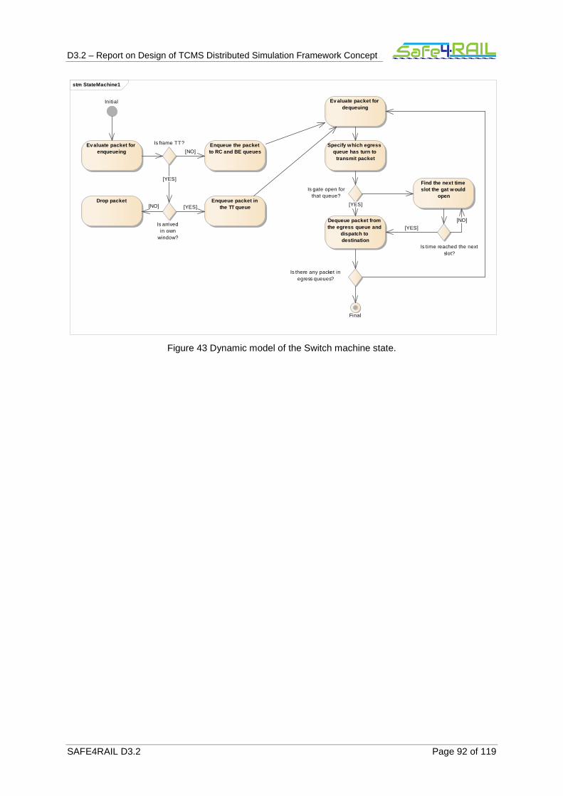
D3.2 – Report on Design of TCMS Distributed Simulation Framework Concept
SAFE4RAIL D3.2 Page 92 of 119
Figure 43 Dynamic model of the Switch machine state.
stm StateMachine1
Evaluate packet for enqueueing
Is frame TT?
Is arrivedin own
window?
Drop packet
Enqueue the packet to RC and BE queues
Enqueue packet in the TT queue
Ini tial Ev aluate packet for dequeuing
Specify which egress queue has turn to
transmit packet
Is gate open forthat queue?
Dequeue packet from the egress queue and
dispatch to destination
Find the next time slot the gat would
open
Is time reached the nextslot?
Is there any packet inegress queues?
Final
[NO] [YES]
[NO]
[YES]
[NO]
[YES]
[YES]
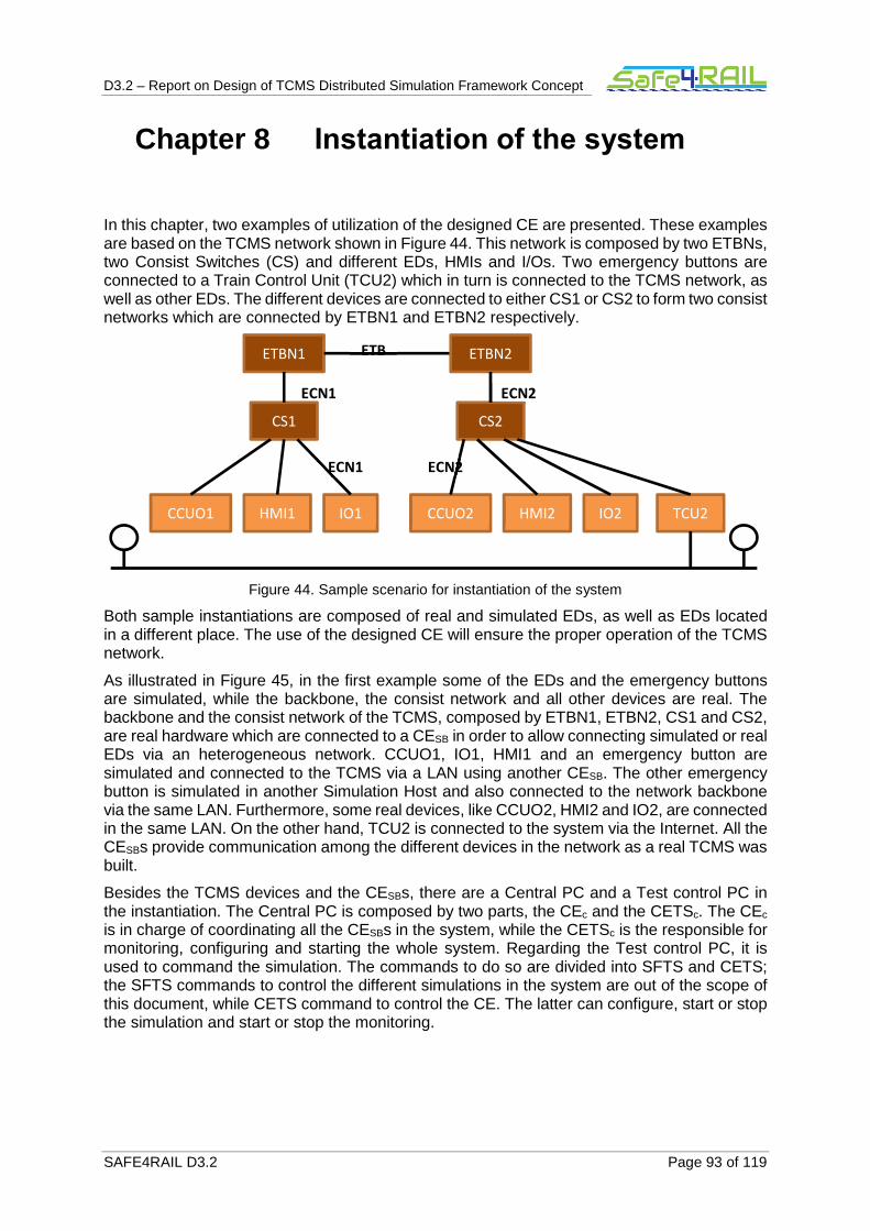
D3.2 – Report on Design of TCMS Distributed Simulation Framework Concept
SAFE4RAIL D3.2 Page 93 of 119
Chapter 8 Instantiation of the system
In this chapter, two examples of utilization of the designed CE are presented. These examples are based on the TCMS network shown in Figure 44. This network is composed by two ETBNs, two Consist Switches (CS) and different EDs, HMIs and I/Os. Two emergency buttons are connected to a Train Control Unit (TCU2) which in turn is connected to the TCMS network, as well as other EDs. The different devices are connected to either CS1 or CS2 to form two consist networks which are connected by ETBN1 and ETBN2 respectively.
Figure 44. Sample scenario for instantiation of the system
Both sample instantiations are composed of real and simulated EDs, as well as EDs located in a different place. The use of the designed CE will ensure the proper operation of the TCMS network.
As illustrated in Figure 45, in the first example some of the EDs and the emergency buttons are simulated, while the backbone, the consist network and all other devices are real. The backbone and the consist network of the TCMS, composed by ETBN1, ETBN2, CS1 and CS2, are real hardware which are connected to a CESB in order to allow connecting simulated or real EDs via an heterogeneous network. CCUO1, IO1, HMI1 and an emergency button are simulated and connected to the TCMS via a LAN using another CESB. The other emergency button is simulated in another Simulation Host and also connected to the network backbone via the same LAN. Furthermore, some real devices, like CCUO2, HMI2 and IO2, are connected in the same LAN. On the other hand, TCU2 is connected to the system via the Internet. All the CESBs provide communication among the different devices in the network as a real TCMS was built.
Besides the TCMS devices and the CESBs, there are a Central PC and a Test control PC in the instantiation. The Central PC is composed by two parts, the CEc and the CETSc. The CEc is in charge of coordinating all the CESBs in the system, while the CETSc is the responsible for monitoring, configuring and starting the whole system. Regarding the Test control PC, it is used to command the simulation. The commands to do so are divided into SFTS and CETS; the SFTS commands to control the different simulations in the system are out of the scope of this document, while CETS command to control the CE. The latter can configure, start or stop the simulation and start or stop the monitoring.
ECN1 CS1
CCUO1
ETBN1 ETBN2 ETB
HMI1 IO1
ECN1
CCUO2 HMI2 IO2 TCU2
CS2 ECN2
ECN2
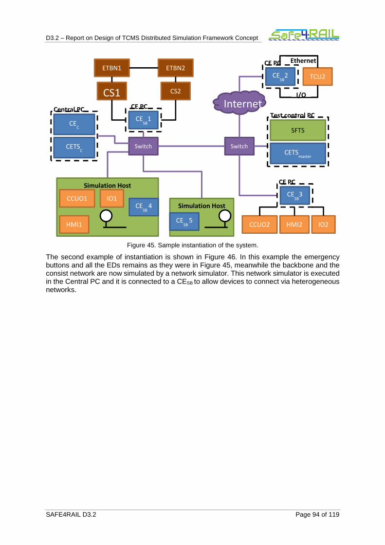
D3.2 – Report on Design of TCMS Distributed Simulation Framework Concept
SAFE4RAIL D3.2 Page 94 of 119
Figure 45. Sample instantiation of the system.
The second example of instantiation is shown in Figure 46. In this example the emergency buttons and all the EDs remains as they were in Figure 45, meanwhile the backbone and the consist network are now simulated by a network simulator. This network simulator is executed in the Central PC and it is connected to a CESB to allow devices to connect via heterogeneous networks.
Simulation Host CCUO1
HMI1
IO1
CCUO2 HMI2 IO2
TCU2
CE PC
CESB
4 Simulation Host
CE PC
Switch Switch
CE PC
I/O
Ethernet
Internet CE
SB1
CS1
ETBN1 ETBN2
CS2
CESB
2
CESB
3
CESB
5
Central PC
CEC
CETSC
Test control PC
SFTS
CETSmaster
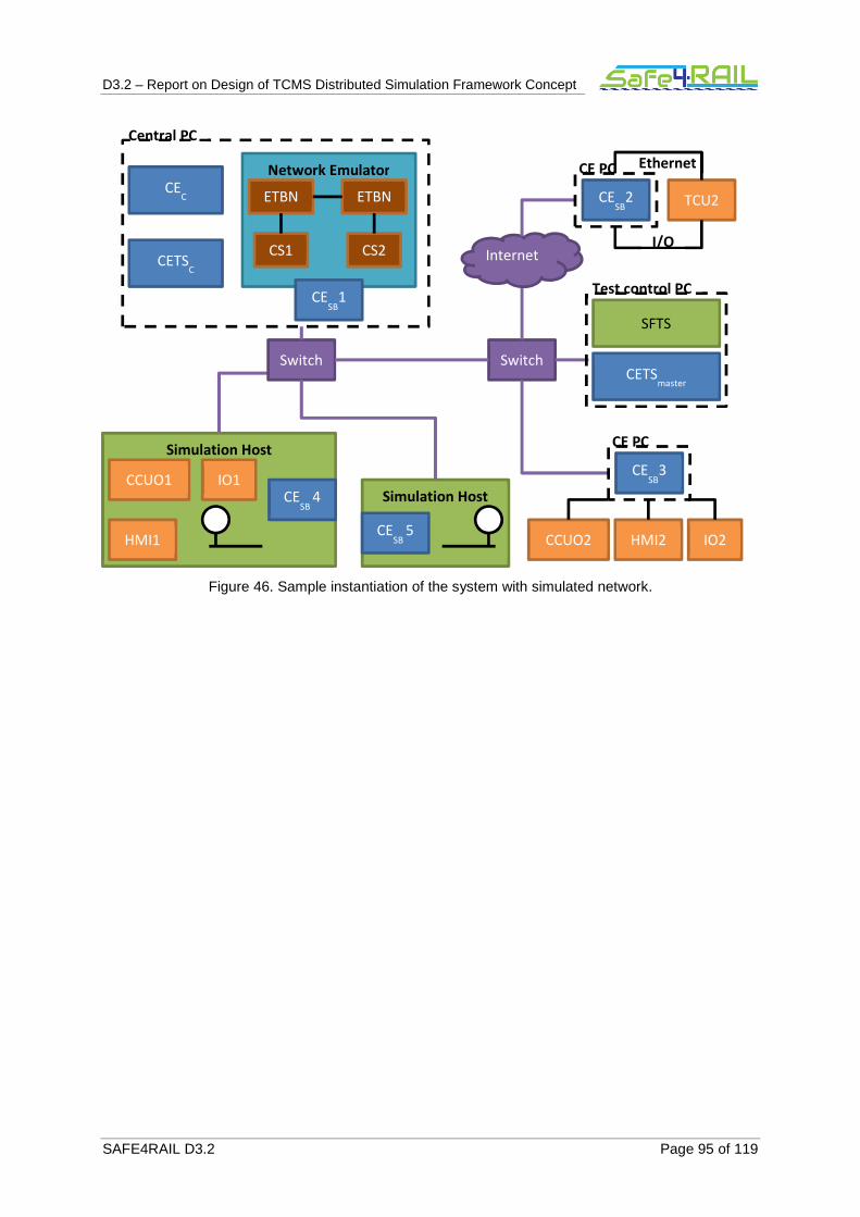
D3.2 – Report on Design of TCMS Distributed Simulation Framework Concept
SAFE4RAIL D3.2 Page 95 of 119
Figure 46. Sample instantiation of the system with simulated network.
Network Emulator
Simulation Host CCUO1
HMI1
IO1
CCUO2 HMI2 IO2
TCU2
CESB
4 Simulation Host
CE PC
Switch Switch
CE PC
I/O
Ethernet
Internet
CESB
1
CS1
ETBN
1 ETBN
2
CS2
CESB
2
CESB
3
CESB
5
Central PC
CEC
CETSC
Test control PC
SFTS
CETSmaster
D3.2 – Report on Design of TCMS Distributed Simulation Framework Concept
SAFE4RAIL D3.2 Page 96 of 119
Chapter 9 Summary and conclusions
In this deliverable, a high-level design of a Communication Emulator (CE) to test and validate Train Control and Monitoring Systems (TCMS) has been presented. The proposed design allows connecting different devices typically found in TCMS via a heterogeneous network. End Devices (ED), Vehicular Control Unit (VCU) and Human Machine Interface (HMI) can be connected to the CE to build up the TCMS network and carry out different tests and/or validations. Furthermore, both real devices and simulated models for the EDs, VCUs and HMIs are supported by the system.
The design of the system has been presented through several Unified Modelling Language (UML) diagrams. The uses cases of the system and its scope, architectural and dynamic models have been shown in this document. Moreover, a dynamic model has been presented for each subsystem, as well as a sequence diagram for each use case where the interactions among the subsystems are shown.
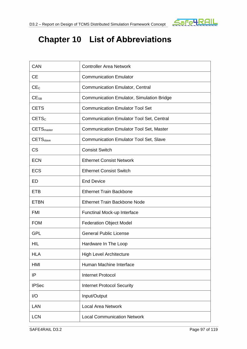
D3.2 – Report on Design of TCMS Distributed Simulation Framework Concept
SAFE4RAIL D3.2 Page 97 of 119
Chapter 10 List of Abbreviations
CAN Controller Area Network
CE Communication Emulator
CEC Communication Emulator, Central
CESB Communication Emulator, Simulation Bridge
CETS Communication Emulator Tool Set
CETSC Communication Emulator Tool Set, Central
CETSmaster Communication Emulator Tool Set, Master
CETSslave Communication Emulator Tool Set, Slave
CS Consist Switch
ECN Ethernet Consist Network
ECS Ethernet Consist Switch
ED End Device
ETB Ethernet Train Backbone
ETBN Ethernet Train Backbone Node
FMI Functinal Mock-up Interface
FOM Federation Object Model
GPL General Public License
HIL Hardware In The Loop
HLA High Level Architecture
HMI Human Machine Interface
IP Internet Protocol
IPSec Internet Protocol Security
I/O Input/Output
LAN Local Area Network
LCN Local Communication Network

D3.2 – Report on Design of TCMS Distributed Simulation Framework Concept
SAFE4RAIL D3.2 Page 98 of 119
L2TP Layer Two Tunnelling Protocol
MVB Multifunction Vehicle Bus
OMT Object Model Template
PPTP Point-to-Point Tunneling Protocol
RTI Run-Time Infrastructure
SB Simulation Bridge
SFTS Simulation Framework Tool Set
SIL Software In The Loop
SSL Secure Socket Layer
SSTP Secure Socket Tunnelling Protocol
TT Test Automation Tool
TBN Train Backbone Node
TCMS Train Control and Monitoring System
TCU Train Control Unit
UI User Interface
UML Unified Modelling Language
VCU Vehicle Control Unit
VPN Virtual Private Network
Table 4: List of Abbreviations
D3.2 – Report on Design of TCMS Distributed Simulation Framework Concept
SAFE4RAIL D3.2 Page 99 of 119
Chapter 11 Bibliography
[1] Safe4RAIL, “Report on final requirements, D3.6.”
[2] CONNECTA, “Specification of the Simulation Framework and Train Virtualisation, D6.2.”
[3] Safe4RAIL, “Report on State-of-the-Art Analysis and Initial Requirements for the Distributed Simulation Framework, D3.1.”
[4] M. U. Awais, P. Palensky, A. Elsheikh, E. Widl, and S. Matthias, “The high level architecture RTI as a master to the functional mock-up interface components,” in 2013
International Conference on Computing, Networking and Communications, ICNC 2013, 2013.
[5] J. S. Dahmann, R. M. Fujimoto, and R. M. Weatherly, “THE DoD HIGH LEVEL ARCHITECTURE: AN UPDATE.”
[6] R. M. Fujimoto and R. M. Weatherly, “HLA time management and DIS,” 15th Work.
Stand. Interoperability Distrib. Simulations, pp. 615–628, 1996.
[7] “IEEE Standard for Modeling and Simulation (M&S) High Level Architecture (HLA)-- Federate Interface Specificationt.” pp. 1–378, 2010.
[8] T. Blochwitz et al., “The Functional Mockup Interface for Tool independent Exchange of Simulation Models.”
[9] “Functional Mock-up Interface.” [Online]. Available: https://fmi-standard.org/.
[10] T. Blockwitz et al., “Functional Mockup Interface 2.0: The Standard for Tool independent Exchange of Simulation Models,” pp. 173–184, 2012.
[11] T. Blochwitz et al., “Functional Mockup Interface 2.0: The Standard for Tool independent Exchange of Simulation Models.”
[12] J. Kaur, Aarja and Malhotra, “A survey of network simulation tools,” Wirel. Commun., vol. 7, no. 6, pp. 191--194, 2015.
[13] “OPNET Technologies – Network Simulator | Riverbed: https://www.riverbed.com/es/products/steelcentral/opnet.html?redirect=opnet”
[14] “Virtual Private Networking: An Overview.” [Online]. Available: https://technet.microsoft.com/en-us/library/bb742566.aspx.
[15] Safe4RAIL, “State-of-the-art Document on Drive-by-Data, D1.1.”

D3.2 – Report on Design of TCMS Distributed Simulation Framework Concept
SAFE4RAIL D3.2 Page 100 of 119
[16] “IEC 61375-2-5:2014 Standard.” 2014.
[17] “IEC 61375-3-4:2014 Standard.” 2014.

D3.
2 –
Rep
ort o
n D
esig
n of
TC
MS
Dis
trib
uted
Sim
ulat
ion
Fra
mew
ork
Con
cept
SA
FE
4RA
IL D
3.2
Pag
e 10
1 of
119
Cha
pter
12
Ap
pe
nd
ix 1
: S
eq
ue
nce
dia
gra
ms
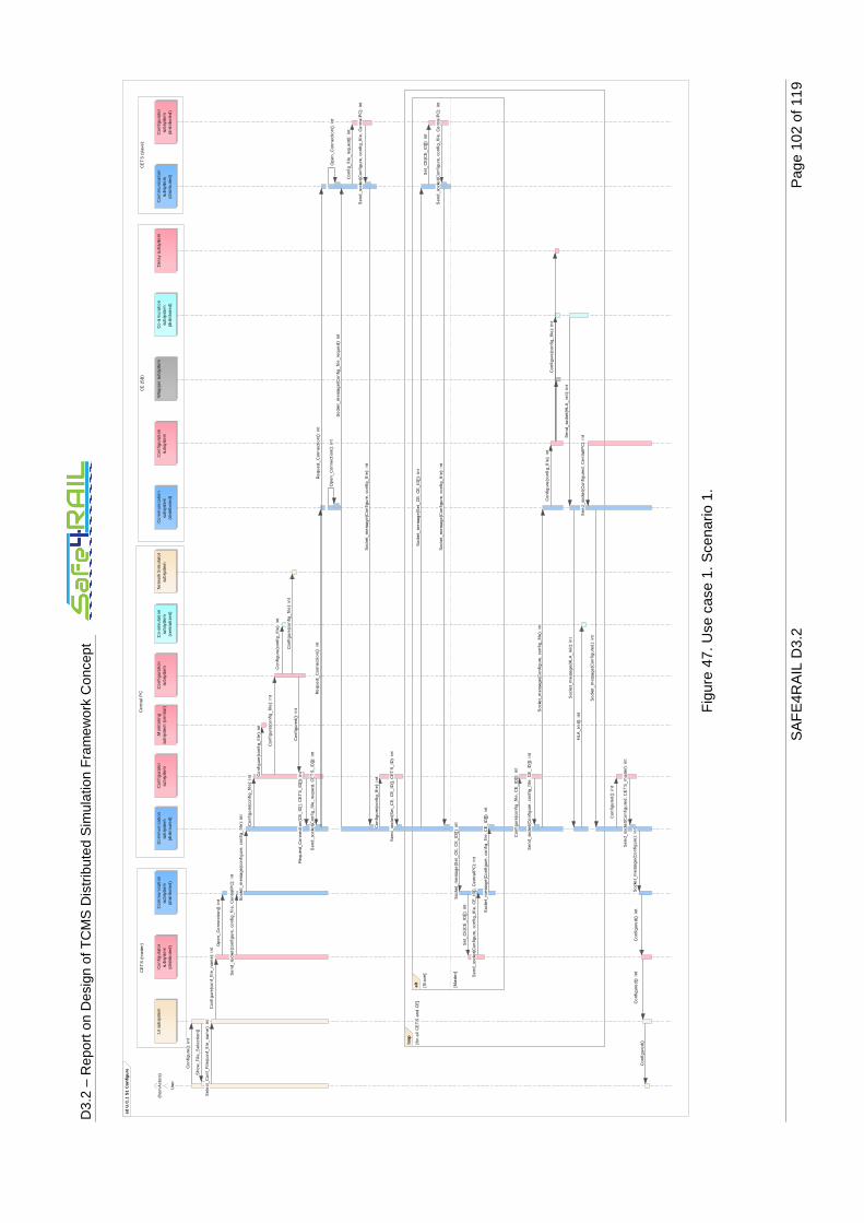
D3.
2 –
Rep
ort o
n D
esig
n of
TC
MS
Dis
trib
uted
Sim
ulat
ion
Fra
mew
ork
Con
cept
SA
FE
4RA
IL D
3.2
Pag
e 10
2 of
119
F
igur
e 47
. Use
cas
e 1.
Sce
nario
1.
sd U
.C.1
S1
Con
figur
e
CE
TS
(sl
ave)
CE
(S
B)
Cen
tra
l PC
CE
TS
(ma
ste
r)
Use
r
(fro
m A
cto
rs)
:UI
sub
syst
em
:Con
fig
urat
or
sub
syst
em
(dis
trib
uted
)
:Co
mm
un
ica
tion
sub
syst
em
(dis
trib
ute
d)
:Co
mm
un
ica
tion
sub
syst
em
(dis
trib
ute
d)
:Co
nfig
ura
tor
sub
syst
em
:Ne
twor
k S
imul
ator
subs
yste
m:C
on
figu
rati
onsu
bsys
tem
:Co
mm
unic
atio
nsu
bsys
tem
(dis
tribu
ted
)
:Co
nfig
ura
tion
subs
yste
m:W
rap
per
sub
syst
em
:Co
-sim
ula
tion
sub
syst
em
(dis
trib
uted
)
:De
lay
sub
syst
em
:Co
mm
un
ica
tio
nsu
bsy
ste
m(d
istr
ibu
ted)
:Co
nfig
ura
tor
sub
syst
em
(dis
trib
ute
d)
:Co-
sim
ula
tion
sub
syst
em
(ce
ntra
lize
d)
:Mon
itor
ing
sub
syst
em
(cen
tra
l)
alt
[Sla
ve]
[Ma
ste
r]
loop
[for
all
CE
TS
an
d C
E]
HLA
_ini
t():
int
Se
nd_
sock
et(C
on
figu
re,
conf
ig_
file,
CE
_ID
[], C
en
tral
PC
): in
t
Se
t_C
E(C
E_
ID[]
): in
t
Se
nd_
sock
et(
con
figu
re,
conf
ig_f
ile,
Ce
ntra
lPC
): in
t
Co
nfig
ure
(con
fig_
file
): in
t
Se
nd_
sock
et(
Co
nfig
ure
, co
nfig
_fil
e, C
E_
ID[])
: int
Op
en_
Co
nne
ctio
n():
int
Co
nfi
gure
(con
fig
_file
): i
nt
Con
figu
re(c
onf
_file
_n
ame
): i
nt
Soc
ket_
me
ssag
e(H
LA
_in
it):
int
Co
nfig
ure
(co
nfi
g_fi
le):
int
Sen
d_
sock
et(
Co
nfig
ure
, co
nfi
g_fi
le,
Ce
ntra
lPC
): i
nt
Req
ues
t_C
onn
ectio
n()
: int
Co
nfi
gure
():
int
Co
nfig
ure
d():
int
Co
nfig
ure
(co
nfi
g_fi
le):
int
So
cke
t_m
ess
ag
e(S
et_
CE
, C
E_
ID[])
: in
t
Re
que
st_
Co
nne
ctio
n():
int
Se
lect
_C
on
f_F
ile(c
onf_
file
_na
me
): in
t
Co
nfig
ure
d():
int
Sen
d_s
ock
et(
Con
fig
ured
, C
en
tralP
C):
int
So
cke
t_m
ess
age
(Co
nfig
_fi
le_r
equ
est
): in
t
Con
figu
re(c
onf
ig_
file)
: in
t
Se
nd_
sock
et(C
on
figu
red
, CE
TS
_m
ast
er):
int
Soc
ket_
me
ssag
e(C
on
figu
re,
con
fig_
file)
: in
t
Se
nd_
sock
et(S
et_
CE
, C
E_
ID[],
CE
TS
_ID
): i
nt
Con
fig
ured
():
int
So
cket
_m
essa
ge(C
onfi
gur
ed):
int
Soc
ket_
me
ssa
ge(S
et_C
E, C
E_
ID[]
): in
t
Co
nfi
g_fi
le_
requ
est
():
int
So
cket
_m
essa
ge(c
onfi
gur
e, c
on
fig_
file
): in
t
Soc
ket_
me
ssa
ge(C
onfi
gure
, co
nfig
_fi
le):
int
Op
en
_Co
nn
ectio
n()
: int
Co
nfig
ure
(co
nfig
_fi
le):
int
Op
en_
Co
nne
ctio
n():
int
Se
nd_
sock
et(H
LA
_in
it):
int
Soc
ket_
me
ssag
e(C
on
figu
re,
con
fig_
file
, CE
_ID
[]):
int
Co
nfig
ure
(co
nfi
g_fi
le):
int
Sen
d_s
ock
et(C
onfi
g_f
ile_
req
uest
, C
ET
S_I
D[]
): in
t
Sh
ow
_Fil
e_S
elec
tion
()
Con
figu
red
(): i
nt
Set
_C
E(C
E_I
D[]
): in
t
Soc
ket_
me
ssa
ge(C
onfi
gure
, co
nfig
_fi
le):
int
Re
que
st_
Co
nne
ctio
n(C
E_
ID[]
, C
ET
S_
ID[])
: in
t
So
cke
t_m
ess
age
(Co
nfig
ure
): in
t
Co
nfig
ure
d()
Con
figu
re(c
onf
ig_
file,
CE
_ID
[]):
int
Sen
d_
sock
et(
Co
nfig
ure
, co
nfi
g_fi
le,
Ce
ntra
lPC
): i
nt
Co
nfig
ure
(co
nfig
_fi
le):
int

D3.
2 –
Rep
ort o
n D
esig
n of
TC
MS
Dis
trib
uted
Sim
ulat
ion
Fra
mew
ork
Con
cept
SA
FE
4RA
IL D
3.2
Pag
e 10
3 of
119
Fig
ure
48. U
se c
ase
1. S
cena
rio 2
.
sd U
.C.1
S2
Con
figur
e
Ce
ntr
al
PC
CE
TS
(m
ast
er)
Use
r
(fro
m A
cto
rs)
:UI
sub
syst
em
:Co
nfi
gu
rato
rsu
bsy
ste
m(d
istr
ibu
ted
)
:Co
mm
un
ica
tio
nsu
bsy
ste
m:C
om
mu
nic
ati
on
sub
syst
em
:Co
nfi
gu
rato
rsu
bsy
ste
m
Err
or(
ma
ste
r_a
lre
ad
y_a
ssig
ne
d):
int
Err
or(
ma
ste
r_a
lre
ad
y_a
ssig
ne
d)
Se
nd
_so
cke
t(co
nfi
gu
re,
con
fig
_fi
le,
Ce
ntr
alP
C):
in
t
Sh
ow
_F
ile
_S
ele
ctio
n()
Op
en
_C
on
ne
ctio
n()
: in
t
Co
nfi
gu
re(c
on
fig
_fi
le):
in
t
Co
nfi
gu
re(c
on
f_fi
le_
na
me
): i
nt
Se
nd
_so
cke
t(E
rro
r, m
ast
er_
alr
ea
dy_
de
sig
n,
CE
TS
_m
ast
er)
: in
t
Err
or(
ma
ste
r_a
lre
ad
y_a
ssig
ne
d):
in
t
Se
lect
_C
on
f_F
ile
(co
nf_
file
_n
am
e):
in
t
So
cke
t_m
ess
ag
e(E
rro
r, m
ast
er_
alr
ea
dy_
ass
ign
ed
): i
nt
Co
nfi
gu
re()
: in
t
So
cke
t_m
ess
ag
e(c
on
fig
ure
, co
nfi
g_
file
): i
nt

D3.
2 –
Rep
ort o
n D
esig
n of
TC
MS
Dis
trib
uted
Sim
ulat
ion
Fra
mew
ork
Con
cept
SA
FE
4RA
IL D
3.2
Pag
e 10
4 of
119
F
igur
e 49
. Use
cas
e 1.
Sce
nario
3.
sd U
.C.1
S3
Con
figur
e
Ce
ntr
al
PC
CE
TS
(m
ast
er)
Use
r
(fro
m A
cto
rs)
:UI
sub
syst
em
:Co
nfi
gu
rato
rsu
bsy
ste
m(d
istr
ibu
ted
)
:Co
mm
un
ica
tio
nsu
bsy
ste
m:C
om
mu
nic
ati
on
sub
syst
em
:Co
nfi
gu
rato
rsu
bsy
ste
m
So
cke
t_m
ess
ag
e(E
rro
r, c
on
fig
_fi
le_
err
or)
: in
t
Co
nfi
gu
re(c
on
fig
_fi
le):
in
t
Err
or(
con
fig
_fi
le_
err
or)
Op
en
_C
on
ne
ctio
n()
: in
t
Co
nfi
gu
re()
: in
t
Err
or(
con
fig
_fi
le_
err
or)
: in
t
So
cke
t_m
ess
ag
e(c
on
fig
ure
, co
nfi
g_
file
): i
nt
Se
nd
_so
cke
t(co
nfi
gu
re,
con
fig
_fi
le,
Ce
ntr
alP
C):
in
t
Co
nfi
gu
re(c
on
f_fi
le_
na
me
): i
nt
Se
lect
_C
on
f_F
ile
(co
nf_
file
_n
am
e):
in
t
Sh
ow
_F
ile
_S
ele
ctio
n()
Err
or(
con
fig
_fi
le_
err
or)
: in
t
Se
nd
_so
cke
t(E
rro
r, c
on
fig
_fi
le_
err
or,
CE
TS
_m
ast
er)
: in
t

D3.
2 –
Rep
ort o
n D
esig
n of
TC
MS
Dis
trib
uted
Sim
ulat
ion
Fra
mew
ork
Con
cept
SA
FE
4RA
IL D
3.2
Pag
e 10
5 of
119
Fig
ure
50. U
se c
ase
2. S
cena
rio 1
.
sd U
.C.2
S1
Rec
onfig
ure
CE
(S
B)
Ce
ntr
al
PC
CE
TS
(m
ast
er)
Use
r
(fro
m A
cto
rs)
:UI
sub
syst
em
:Co
nfi
gu
rato
rsu
bsy
ste
m(d
istr
ibu
ted
)
:Co
mm
un
ica
tio
nsu
bsy
ste
m:C
om
mu
nic
ati
on
sub
syst
em
:Co
nfi
gu
rato
rsu
bsy
ste
m:N
etw
ork
Sim
ula
tor
sub
syst
em
:Co
nfi
gu
rati
on
sub
syst
em
:Co
mm
un
ica
tio
nsu
bsy
ste
m:C
on
fig
ura
tio
nsu
bsy
ste
m:W
rap
pe
rsu
bsy
ste
m:C
o-s
imu
lati
on
sub
syst
em
(dis
trib
ute
d)
:Co
-sim
ula
tio
nsu
bsy
ste
m(c
en
tra
lize
d)
So
cke
t_m
ess
ag
e(C
on
fig
ure
d):
in
t
So
cke
t_m
ess
ag
e(H
LA
_in
it):
in
t
Sh
ow
_F
ile
_S
ele
ctio
n()
Se
nd
_so
cke
t(C
on
fig
ure
d,
CE
TS
_m
ast
er)
: in
t
Se
nd
_so
cke
t(H
LA
_in
it,
Ce
ntr
alP
C):
in
t
Co
nfi
gu
re(r
eco
nfi
g_
file
):in
t
Ch
eck
_co
nn
ect
ion
():
int
Ch
eck
_co
nn
ect
ion
():
int
So
cke
t_m
ess
ag
e(C
on
fig
ure
d):
in
t
Se
lect
_C
on
f_F
ile
(re
con
f_fi
le_
na
me
): i
nt
Co
nfi
gu
red
():
int
HL
A_
init
():
int
Co
nfi
gu
re(r
eco
nf_
file
): i
nt
Co
nfi
gu
re(r
eco
nf_
file
): i
nt
Re
con
fig
ure
():
int
Co
nfi
gu
red
():
int
So
cke
t_m
ess
ag
e(r
eco
nf_
file
): i
nt
So
cke
t_m
ess
ag
e(r
eco
nfi
gu
re,
con
fig
_fi
le):
in
t
Co
nfi
gu
red
()
Co
nfi
gu
re(r
eco
nf_
file
): i
nt
Se
nd
_so
cke
t(re
con
fig
ure
, re
con
f_fi
le):
in
t
Co
nfi
gu
red
():
int
Co
nfi
gu
re(r
eco
nf_
file
): i
nt
Re
con
fig
ure
(re
con
f_fi
le_
na
me
): i
nt
Se
nd
_so
cke
t(C
on
fig
ure
d,
Ce
ntr
alP
C):
in
t
Se
nd
_so
cke
t(re
con
f_fi
le,
CE
_ID
[]):
in
t
Co
nfi
gu
red
():
int
Co
nfi
gu
re(r
eco
nf_
file
): i
nt

D3.
2 –
Rep
ort o
n D
esig
n of
TC
MS
Dis
trib
uted
Sim
ulat
ion
Fra
mew
ork
Con
cept
SA
FE
4RA
IL D
3.2
Pag
e 10
6 of
119
Fig
ure
51. U
se c
ase
2. S
cena
rio 2
.
sd U
.C.2
S2
Rec
onfig
ure
Ce
ntr
al
PC
CE
TS
(m
ast
er)
Use
r
(fro
m A
cto
rs)
:UI
sub
syst
em
:Co
nfi
gu
rato
rsu
bsy
ste
m(d
istr
ibu
ted
)
:Co
mm
un
ica
tio
nsu
bsy
ste
m:C
om
mu
nic
ati
on
sub
syst
em
:Co
nfi
gu
rato
rsu
bsy
ste
m
Err
or(
reco
nfi
gu
re_
file
_e
rro
r)
Ch
eck
_co
nn
ect
ion
():
int
Co
nfi
gu
re(r
eco
nfi
g_
file
): i
nt
Re
con
fig
ure
(re
con
f_fi
le_
na
me
):in
t
So
cke
t_m
ess
ag
e(r
eco
nfi
gu
re,
reco
nfi
g_
file
): i
nt
Sh
ow
_F
ile
_S
ele
ctio
n()
Se
nd
_so
cke
t(E
rro
r, r
eco
nfi
gu
re_
file
_e
rro
r):
int
So
cke
t_m
ess
ag
e(E
rro
r, r
eco
nfi
gu
re_
file
_e
rro
r):
int
Err
or(
reco
nfi
gu
re_
file
_e
rro
r):
int
Re
con
fig
ure
():
int
Se
nd
_so
cke
t(re
con
fig
ure
, re
con
fig
_fi
le,
Ce
ntr
alP
C):
in
t
Se
lect
_C
on
f_F
ile
(re
con
f_fi
le_
na
me
):in
t
Err
or(
reco
nfi
gu
re_
file
_e
rro
r):
int

D3.
2 –
Rep
ort o
n D
esig
n of
TC
MS
Dis
trib
uted
Sim
ulat
ion
Fra
mew
ork
Con
cept
SA
FE
4RA
IL D
3.2
Pag
e 10
7 of
119
Fig
ure
52. U
se c
ase
3. S
cena
rio 1
.
sd U
.C.3
S1
SF
TS c
omm
ands
CE
2 (
SB
)C
en
tra
l P
CC
E1
(S
B)
Sim
ula
tio
n F
ram
ew
ork
To
ols
et
(fro
m A
cto
rs)
:Wra
pp
er
sub
syst
em
:Co
-sim
ula
tio
nsu
bsy
ste
m(d
istr
ibu
ted
)
:Co
mm
un
ica
tio
nsu
bsy
ste
m(d
istr
ibu
ted
)
:Co
mm
un
ica
tio
nsu
bsy
ste
m(d
istr
ibu
ted
)
:Co
mm
un
ica
tio
nsu
bsy
ste
m(d
istr
ibu
ted
)
:Co
-sim
ula
tio
nsu
bsy
ste
m(d
istr
ibu
ted
)
:De
lay
sub
syst
em
:Wra
pp
er
sub
syst
em
SW
ED
, V
CU
, H
MI,
I/O
Bo
ard
s
(fro
m A
cto
rs)
:Co
-sim
ula
tio
nsu
bsy
ste
m(c
en
tra
lize
d)
:Fa
ult
in
ject
ion
sub
syst
em
Inte
ract
ion
_m
ess
ag
e(c
om
ma
nd
_S
FT
S):
in
t
Inte
ract
ion
_w
rap
pe
r(co
mm
an
d_
SF
TS
): i
nt
Inte
ract
ion
_m
ess
ag
e(c
om
ma
nd
_S
FT
S):
in
t
Se
nd
_in
tera
ctio
n(c
om
ma
nd
_S
FT
S):
in
t
Co
mm
an
d_
SF
TS
():
int
Inte
ract
ion
_w
rap
pe
r(co
mm
an
d_
SF
TS
): i
nt
Inte
ract
ion
_su
bsc
rib
ers
(co
mm
an
d_
SF
TS
): i
nt
Se
nd
_in
tera
ctio
n(c
om
ma
nd
_S
FT
S):
in
t
Co
mm
an
d_
SF
TS
()
Inte
ract
ion
_p
rod
uce
d(c
om
ma
nd
_S
FT
S):
in
t
Inte
ract
ion
_w
rap
pe
r(co
mm
an
d_
SF
TS
): i
nt
Inte
ract
ion
_p
rod
uce
d(c
om
ma
nd
_S
FT
S):
in
t

D3.
2 –
Rep
ort o
n D
esig
n of
TC
MS
Dis
trib
uted
Sim
ulat
ion
Fra
mew
ork
Con
cept
SA
FE
4RA
IL D
3.2
Pag
e 10
8 of
119
Fig
ure
53. U
se c
ase
4. S
cena
rio 1
.
sd U
.C.4
S1
Eth
erne
t int
era
ctio
n
CE
2 (
SB
)C
en
tra
l P
CC
E1
(S
B)
:Wra
pp
er
sub
syst
em
:Co
-sim
ula
tio
nsu
bsy
ste
m(d
istr
ibu
ted
)
:Co
mm
un
ica
tio
nsu
bsy
ste
m(d
istr
ibu
ted
)
:Co
mm
un
ica
tio
nsu
bsy
ste
m(d
istr
ibu
ted
)
:Co
mm
un
ica
tio
nsu
bsy
ste
m(d
istr
ibu
ted
)
:Co
-sim
ula
tio
nsu
bsy
ste
m(d
istr
ibu
ted
)
:De
lay
sub
syst
em
:Wra
pp
er
sub
syst
em
SW
ED
, V
CU
, H
MI,
I/O
Bo
ard
s
(fro
m A
cto
rs)
Re
al
ED
, V
CU
, H
MI,
I/O
Bo
ard
s
(fro
m A
cto
rs)
:Co
-sim
ula
tio
nsu
bsy
ste
m(c
en
tra
lize
d)
:Fa
ult
in
ject
ion
sub
syst
em
Eth
ern
et_
fra
me
()
Inte
ract
ion
_p
rod
uce
d(e
the
rne
t_fr
am
e):
in
t
Inte
ract
ion
_w
rap
pe
r(e
the
rne
t_fr
am
e):
in
t
Inte
ract
ion
_su
bsc
rib
ers
(eth
ern
et_
fra
me
): i
nt
Inte
ract
ion
_m
ess
ag
e(e
the
rne
t_fr
am
e):
in
t
Inte
ract
ion
_m
ess
ag
e(e
the
rne
t_fr
am
e):
in
t
Se
nd
_in
tera
ctio
n(e
the
rne
t_fr
am
e):
in
t
Inte
ract
ion
_w
rap
pe
r(e
the
rne
t_fr
am
e):
in
t
Se
nd
_in
tera
ctio
n(e
the
rne
t_fr
am
e):
in
t
Inte
ract
ion
_p
rod
uce
d(e
the
rne
t_fr
am
e):
in
t
Inte
ract
ion
_w
rap
pe
r(e
the
rne
t_fr
am
e):
in
t
Eth
ern
et_
fra
me
():
int

D3.
2 –
Rep
ort o
n D
esig
n of
TC
MS
Dis
trib
uted
Sim
ulat
ion
Fra
mew
ork
Con
cept
SA
FE
4RA
IL D
3.2
Pag
e 10
9 of
119
Fig
ure
54. U
se c
ase
5. S
cena
rio 1
.
sd U
.C.5
S1
I/O
inte
ract
ion
CE
2 (
SB
)C
en
tra
l P
CC
E1
(S
B)
Re
al
ED
, V
CU
, H
MI,
I/O
Bo
ard
s
(fro
m A
cto
rs)
:Wra
pp
er
sub
syst
em
:Co
-sim
ula
tio
nsu
bsy
ste
m(d
istr
ibu
ted
)
:Co
mm
un
ica
tio
nsu
bsy
ste
m(d
istr
ibu
ted
)
:Co
mm
un
ica
tio
nsu
bsy
ste
m(d
istr
ibu
ted
)
:Co
mm
un
ica
tio
nsu
bsy
ste
m(d
istr
ibu
ted
)
:Co
-sim
ula
tio
nsu
bsy
ste
m(d
istr
ibu
ted
)
:De
lay
sub
syst
em
:Wra
pp
er
sub
syst
em
SW
ED
, V
CU
, H
MI,
I/O
Bo
ard
s
(fro
m A
cto
rs)
:Co
-sim
ula
tio
nsu
bsy
ste
m(c
en
tra
lize
d)
:Fa
ult
in
ject
ion
sub
syst
em
Se
nd
_in
tera
ctio
n(i
/o):
in
t
Inte
ract
ion
_su
bsc
rib
ers
(i/o
): i
nt
Inte
ract
ion
_w
rap
pe
r(i/
o):
in
t
Inte
ract
ion
_p
rod
uce
d(i
/o):
in
t
Inte
ract
ion
_w
rap
pe
r(i/
o):
in
t
Inte
ract
ion
_m
ess
ag
e(i
/o):
in
t
I/O
():
int
I/O
()
Inte
ract
ion
_w
rap
pe
r(i/
o):
in
t
Inte
ract
ion
_m
ess
ag
e(i
/o):
in
t
Inte
ract
ion
_p
rod
uce
d(i
/o):
in
t
Se
nd
_in
tera
ctio
n(i
/o):
in
t

D3.
2 –
Rep
ort o
n D
esig
n of
TC
MS
Dis
trib
uted
Sim
ulat
ion
Fra
mew
ork
Con
cept
SA
FE
4RA
IL D
3.2
Pag
e 11
0 of
119
Fig
ure
55. U
se c
ase
6. S
cena
rio 1
.
sd U
.C.6
S1
Mon
itorin
g st
art
CE
(S
B)
Ce
ntr
al
PC
CE
TS
(m
ast
er)
Use
r
(fro
m A
cto
rs)
:UI
sub
syst
em
:Mo
nit
ori
ng
sub
syst
em
(dis
trib
ute
d)
:Co
mm
un
ica
tio
nsu
bsy
ste
m(d
istr
ibu
ted
)
:Co
mm
un
ica
tio
nsu
bsy
ste
m(d
istr
ibu
ted
)
:Co
mm
un
ica
tio
nsu
bsy
ste
m(d
istr
ibu
ted
)
:Wra
pp
er
sub
syst
em
Re
al
ED
, V
CU
, H
MI,
I/O
Bo
ard
s
(fro
m A
cto
rs)
:Mo
nit
ori
ng
sub
syst
em
:Mo
nit
ori
ng
sub
syst
em
(ce
ntr
al)
alt
[Mo
nio
trin
g]
[Me
asu
rem
en
ts]
Mo
nit
ori
ng
_st
art
(CE
_ID
, h
as_
file
): i
nt
Se
nd
_so
cke
t(m
on
ito
rin
g_
da
ta,
eth
ern
et_
fra
me
, C
E_
ID,
Ce
ntr
alP
C):
in
t
Mo
nit
ori
ng
_d
ata
(eth
ern
et_
fra
me
): i
nt
Mo
nit
ori
ng
_st
art
(CE
_ID
, h
as_
file
): i
nt
So
cke
t_m
ess
ag
e(M
on
ito
rin
g_
sta
rt,
CE
_ID
, h
as_
file
): i
nt
Mo
nit
ori
ng
_d
ata
(eth
ern
et_
fra
me
, C
E_
ID):
in
t
Se
nd
_so
cke
t(M
on
ito
rin
g_
sta
rt,
CE
_ID
, h
as_
file
, C
en
tra
lPC
): i
nt
Mo
nit
oir
ng
_d
ata
( e
the
rne
t_fr
am
e,
CE
_ID
)Mo
nit
ori
ng
_d
ata
(eth
ern
et_
fra
me
, C
E_
ID):
in
t
So
cke
t_m
ess
ag
e(m
on
ito
rin
g_
da
ta,
eth
ern
et_
fra
me
, C
E_
ID):
in
t
Mo
nit
ori
ng
_d
ata
(eth
ern
et_
fra
me
,CE
_ID
): i
nt
Inte
ract
ion
_p
rod
uce
d(e
the
rne
t_fr
am
e):
in
t
So
cke
t_m
ess
ag
e(m
on
ito
rin
g_
da
ta,
eth
ern
et_
fra
me
,CE
_ID
): i
nt
Eth
ern
et_
fra
me
():
int
Mo
nit
ori
ng
_st
art
(CE
_ID
, h
as_
file
): i
nt
So
cke
t_m
ess
ag
e(M
on
ito
rin
g_
sta
rt,
CE
_ID
, h
as_
file
, C
en
tra
lPC
): i
nt
Se
nd
_so
cke
t(M
on
ito
rin
g_
sta
rt,
CE
_ID
, h
as_
file
, C
E_
ID):
in
t
Mo
nit
ori
ng
_st
art
(CE
_ID
, h
as_
file
): i
nt
Se
nd
_so
cke
t(m
on
ito
rin
g_
da
ta,
eth
ern
et_
fra
me
, C
E_
ID,
CE
TS
_m
ast
er)
: in
t

D3.
2 –
Rep
ort o
n D
esig
n of
TC
MS
Dis
trib
uted
Sim
ulat
ion
Fra
mew
ork
Con
cept
SA
FE
4RA
IL D
3.2
Pag
e 11
1 of
119
Fig
ure
56. U
se c
ase
6. S
cena
rio 2
.
sd U
.C.6
S2
Mon
itorin
g st
art
CE
(S
B)
CE
TS
(sl
ave
)
Use
r
(fro
m A
cto
rs)
:UI
sub
syst
em
:Mo
nit
ori
ng
sub
syst
em
(dis
trib
ute
d)
:Co
mm
un
ica
tio
nsu
bsy
ste
m(d
istr
ibu
ted
)
:Co
mm
un
ica
tio
nsu
bsy
ste
m(d
istr
ibu
ted
)
:Wra
pp
er
sub
syst
em
Re
al
ED
, V
CU
, H
MI,
I/O
Bo
ard
s
(fro
m A
cto
rs)
:Mo
nit
ori
ng
sub
syst
em
alt
[Mo
nit
ori
ng
]
[Me
asu
rem
en
ts]
So
cke
t_m
ess
ag
e(m
on
ito
rin
g_
da
ta,
eth
ern
et_
fra
me
,CE
TS
_ID
): i
nt
Mo
nit
ori
ng
_st
art
(CE
_ID
, h
as_
file
): i
nt
So
cke
t_m
ess
ag
e(M
on
ito
rin
g_
sta
rt,
CE
_ID
, h
as_
file
, C
E_
ID):
in
t
Se
nd
_so
cke
t(M
on
ito
rin
g_
sta
rt,
CE
_ID
, h
as_
file
, C
en
tra
lPC
): i
nt
Eth
ern
et_
fra
me
():
int
Mo
nit
ori
ng
_d
ata
(eth
ern
et_
fra
me
, C
E_
ID):
in
t
Mo
nit
ori
ng
_d
ata
(eth
ern
et_
fra
me
, C
E_
ID):
in
t
Mo
nit
ori
ng
_st
art
(CE
_ID
, h
as_
file
): i
nt
Inte
ract
ion
_p
rod
uce
d(e
the
rne
t_fr
am
e):
in
t
Mo
nit
ori
ng
_st
art
(CE
_ID
, h
as_
file
): i
nt
Se
nd
_so
cke
t(m
on
ito
rin
g_
da
ta,
eth
ern
et_
fra
me
, C
E_
ID,
Ce
ntr
alP
C):
in
t
Sto
re_
da
ta(e
the
rne
t_fr
am
e):
in
t
Mo
nit
oir
ng
_d
ata
( e
the
rne
t_fr
am
e,
CE
_ID
)

D3.
2 –
Rep
ort o
n D
esig
n of
TC
MS
Dis
trib
uted
Sim
ulat
ion
Fra
mew
ork
Con
cept
SA
FE
4RA
IL D
3.2
Pag
e 11
2 of
119
Fig
ure
57. U
se c
ase
7. S
cena
rio 1
.
sd U
.C.7
S1
Mon
itori
ng s
top
CE
(S
B)
Ce
ntr
al
PC
CE
TS
(m
ast
er)
Use
r
(fro
m A
cto
rs)
:UI
sub
syst
em
:Mo
nit
ori
ng
sub
syst
em
(dis
trib
ute
d)
:Co
mm
un
ica
tio
nsu
bsy
ste
m(d
istr
ibu
ted
)
:Co
mm
un
ica
tio
nsu
bsy
ste
m(d
istr
ibu
ted
)
:Co
mm
un
ica
tio
nsu
bsy
ste
m(d
istr
ibu
ted
)
:Mo
nit
ori
ng
sub
syst
em
:Mo
nit
ori
ng
sub
syst
em
(ce
ntr
al)
:Wra
pp
er
sub
syst
em
So
cke
t_m
ess
ag
e(M
on
ito
rin
g_
sto
p,
CE
_ID
): i
nt
Se
nd
_so
cke
t(M
on
ito
rin
g_
sto
p,
CE
_ID
, C
en
tra
lPC
): i
nt
Mo
nit
ori
ng
_st
op
(CE
_ID
): i
nt
Mo
nit
ori
ng
_st
op
(CE
_ID
): i
nt
So
cke
t_m
ess
ag
e(M
on
ito
rin
g_
sto
p,
CE
_ID
): i
nt
Se
nd
_so
cke
t(M
on
ito
rin
g_
sto
p,
CE
_ID
, C
E_
ID):
in
t
Mo
nit
ori
ng
_st
op
(CE
_ID
): i
nt
Mo
nit
ori
ng
_st
op
(CE
_ID
): i
nt

D3.
2 –
Rep
ort o
n D
esig
n of
TC
MS
Dis
trib
uted
Sim
ulat
ion
Fra
mew
ork
Con
cept
SA
FE
4RA
IL D
3.2
Pag
e 11
3 of
119
Fig
ure
58. U
se c
ase
7. S
cena
rio 2
.
sd U
.C.7
S2
Mon
itorin
g st
op
CE
(S
B)
CE
TS
(m
ast
er)
Use
r
(fro
m A
cto
rs)
:UI
sub
syst
em
:Mo
nit
ori
ng
sub
syst
em
(dis
trib
ute
d)
:Co
mm
un
ica
tio
nsu
bsy
ste
m(d
istr
ibu
ted
)
:Co
mm
un
ica
tio
nsu
bsy
ste
m(d
istr
ibu
ted
)
:Mo
nit
ori
ng
sub
syst
em
:Wra
pp
er
sub
syst
em
Mo
nit
ori
ng
_st
op
(CE
_ID
): i
nt
Mo
nit
ori
ng
_st
op
(CE
_ID
): i
nt
Se
nd
_so
cke
t(M
on
ito
rin
g_
sto
p,
CE
_ID
, C
E_
ID):
in
t
So
cke
t_m
ess
ag
e(M
on
ito
rin
g_
sto
p,
CE
_ID
): i
nt Mo
nit
ori
ng
_st
op
(CE
_ID
): i
nt

D3.
2 –
Rep
ort o
n D
esig
n of
TC
MS
Dis
trib
uted
Sim
ulat
ion
Fra
mew
ork
Con
cept
SA
FE
4RA
IL D
3.2
Pag
e 11
4 of
119
Fig
ure
59. U
se c
ase
8. S
cena
rio 1
.
sd U
.C.8
S1
Con
figur
atio
n da
ta r
equ
est
Ce
ntr
al
PC
CE
TS
(m
ast
er)
Use
r
(fro
m A
cto
rs)
:UI
sub
syst
em
:Co
nfi
gu
rato
rsu
bsy
ste
m(d
istr
ibu
ted
)
:Co
mm
un
ica
tio
nsu
bsy
ste
m:C
om
mu
nic
ati
on
sub
syst
em
:Co
nfi
gu
rato
rsu
bsy
ste
m
Co
nfi
g_
req
ue
st()
: in
t
Co
nfi
g_
file
(co
nfi
g_
file
)
So
cke
t_m
ess
ag
e(C
on
fig
_fi
le,
con
fig
_fi
le):
in
t
Co
nfi
g_
req
ue
st()
: in
t
Se
nd
_so
cke
t(C
on
fig
_fi
le,
con
fig
_fi
le,
CE
TS
_m
ast
er)
: in
t
Co
nfi
g_
file
(co
nfi
g_
file
): i
nt
So
cke
t_m
ess
ag
e(C
on
fig
_re
qu
est
): i
nt
Se
nd
_so
cke
t(C
on
fig
_re
qu
est
, C
en
tra
lPC
): i
nt
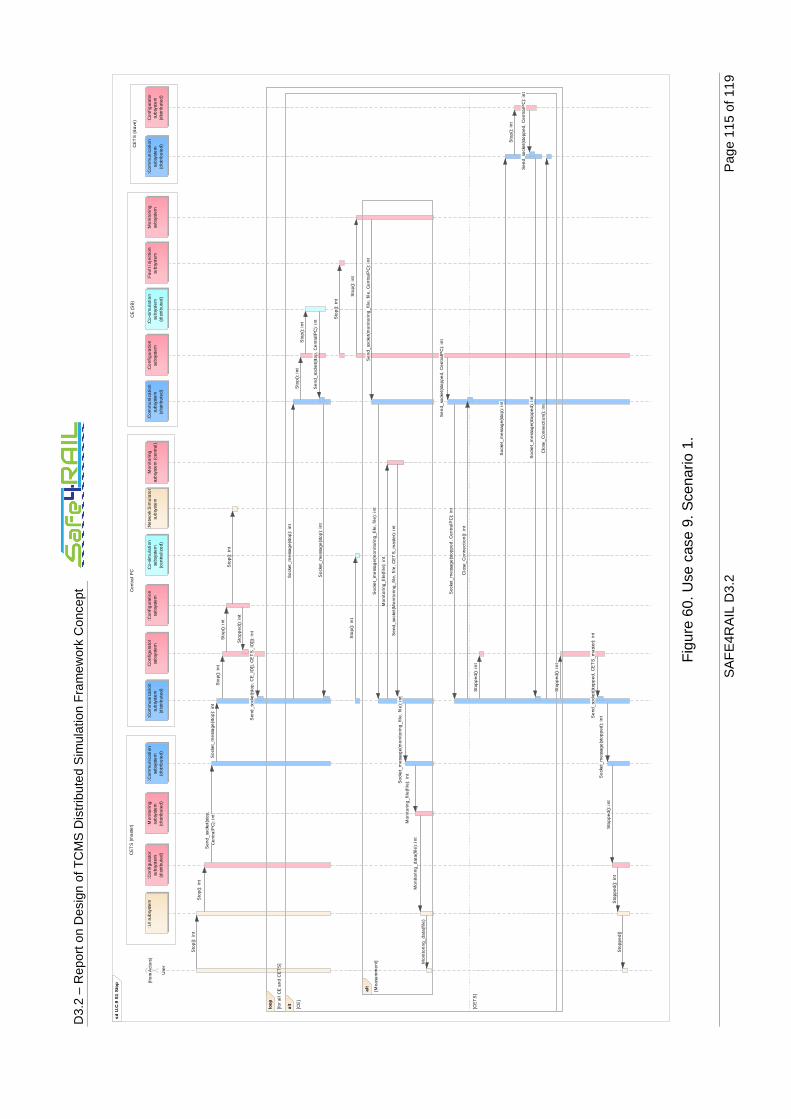
D3.
2 –
Rep
ort o
n D
esig
n of
TC
MS
Dis
trib
uted
Sim
ulat
ion
Fra
mew
ork
Con
cept
SA
FE
4RA
IL D
3.2
Pag
e 11
5 of
119
Fig
ure
60. U
se c
ase
9. S
cena
rio 1
.
sd U
.C.9
S1
Sto
p
CE
(S
B)
CE
TS
(sl
ave
)C
entr
al
PC
CE
TS
(m
ast
er)
Use
r
(fro
m A
cto
rs)
:UI s
ubs
yste
m:C
on
fig
ura
tor
sub
syst
em(d
istri
but
ed)
:Com
mu
nica
tion
subs
yste
m(d
istr
ibu
ted
)
:Co
mm
un
icat
ion
sub
syst
em
(dis
trib
ute
d)
:Co
nfig
ura
tor
sub
syst
em
:Ne
two
rk S
imu
lato
rsu
bsy
ste
m:C
onfi
gu
rati
on
subs
yste
m:C
omm
uni
cati
onsu
bsys
tem
(dis
trib
ute
d)
:Co
nfi
gur
atio
nsu
bsy
ste
m:C
o-s
imu
lati
on
sub
syst
em
(dis
trib
ute
d)
:Co
mm
unic
atio
nsu
bsy
ste
m(d
istr
ibu
ted
)
:Co
nfi
gu
rato
rsu
bsy
ste
m(d
istr
ibu
ted
)
:Mo
nit
orin
gsu
bsy
ste
m:M
oni
tori
ng
sub
syst
em
(dis
trib
ute
d)
:Co-
sim
ula
tion
subs
yste
m(c
en
trali
zed
)
:Mo
nit
ori
ngsu
bsy
ste
m (
cent
ral)
:Fa
ult
in
ject
ion
sub
syst
em
loop
[fo
r al
l C
E a
nd
CE
TS
]
alt
[CE
]
[CE
TS
]
alt
[Me
asu
rem
en
t]
Sto
pp
ed()
: in
t
So
cke
t_m
ess
ag
e(m
on
ito
ring
_fi
le,
file
): i
nt
Sen
d_
sock
et(
stop
, C
E_
ID[]
, C
ET
S_
ID[]
): i
nt
Se
nd
_so
cke
t(sto
pp
ed,
Cen
tra
lPC
): in
t
Sto
p():
int
Se
nd_
sock
et(
stop
,C
en
tra
lPC
): i
nt
So
cke
t_m
ess
age
(sto
p):
int
Sto
pp
ed(
): in
t
Sto
pp
ed
(): i
nt
So
cke
t_m
ess
age
(sto
p):
int
So
cke
t_m
ess
age
(sto
pp
ed):
in
t
Sto
p()
: in
t
Clo
se_
Co
nne
ctio
n():
in
t
Sto
p()
: in
t
Mo
nit
orin
g_
dat
a(f
ile):
in
t
Sto
p()
: in
t
Sto
p():
int
Soc
ket_
me
ssa
ge
(sto
ppe
d,
Ce
ntr
alP
C):
in
t
Sto
p():
int
Sto
p():
int
So
cket
_m
ess
ag
e(s
top
): i
nt
So
cke
t_m
ess
age
(sto
p):
int
Sto
pp
ed
(): i
nt
So
cke
t_m
essa
ge(
mo
nito
rin
g_
file
, fil
e):
int
Clo
se_
Con
ne
ctio
n():
int
Se
nd_
sock
et(
stop
pe
d,
CE
TS
_m
ast
er):
int
So
cke
t_m
essa
ge(
sto
pp
ed
): in
t
Mon
ito
rin
g_d
ata
(fil
e)
Sen
d_
sock
et(
mo
nit
orin
g_
file
, fil
e,
Ce
ntr
alP
C):
in
t
Sto
p():
int
Se
nd_
sock
et(s
top
, Ce
ntra
lPC
): i
nt
Se
nd_
sock
et(
Mo
nit
orin
g_
file
, fi
le,
CE
TS
_m
ast
er):
int
Mo
nit
ori
ng_
file
(fil
e):
int
Sto
p()
: in
t
Sto
p()
: in
t
Mo
nit
orin
g_
file
(fil
e):
int
Sto
p()
: in
t
Sto
pp
ed
(): i
nt
Sto
pp
ed
()
Se
nd
_soc
ket(s
top
ped
, C
entr
alP
C):
int

D3.
2 –
Rep
ort o
n D
esig
n of
TC
MS
Dis
trib
uted
Sim
ulat
ion
Fra
mew
ork
Con
cept
SA
FE
4RA
IL D
3.2
Pag
e 11
6 of
119
Fig
ure
61. U
se c
ase
10. S
cena
rio 1
.
sd U
.C.1
0 S
1 F
aul
t inj
ect
ion
sta
rt
CE
TS
(sl
ave
)C
en
tra
l P
CC
E (
SB
)
Use
r
(fro
m A
cto
rs)
:UI
sub
syst
em
:Co
mm
un
ica
tio
nsu
bsy
ste
m(d
istr
ibu
ted
)
:Co
mm
un
ica
tio
nsu
bsy
ste
m(d
istr
ibu
ted
)
:Co
mm
un
ica
tio
nsu
bsy
ste
m(d
istr
ibu
ted
)R
ea
l E
D,
VC
U,
HM
I, I
/OB
oa
rds
(fro
m A
cto
rs)
:Co
nfi
gu
rato
rsu
bsy
ste
m(d
istr
ibu
ted
)
:Fa
ult
in
ject
ion
sub
syst
em
:Wra
pp
er
sub
syst
em
:Co
nfi
gu
rato
rsu
bsy
ste
m:C
o-s
imu
lati
on
sub
syst
em
(dis
trib
ute
d)
:De
lay
sub
syst
em
Inte
ract
ion
_w
rap
pe
r(e
the
rne
t_fr
am
e):
in
t
Inte
ract
ion
_w
rap
pe
r(e
the
rne
t_fr
am
e):
in
t
Se
nd
_so
cke
t(F
au
lt_
inje
ctio
n,
CE
_ID
, F
au
lt_
typ
e):
in
t
Fa
ult
_in
ject
ion
(CE
_ID
, F
au
lt_
typ
e):
in
t
Eth
ern
et_
fra
me
()
So
cke
t_m
ess
ag
e(F
au
lt_
inje
ctio
n,
CE
_ID
, F
au
lt_
typ
e):
in
t
Fa
ult
_in
ject
ion
(CE
_ID
, F
au
lt_
typ
e):
in
t
Inje
ct_
fau
lt()
: in
t
Inte
ract
ion
_su
bsc
rib
ers
(eth
ern
et_
fra
me
):in
t
Fa
ult
_in
ject
ion
(Fa
ult
_ty
pe
): i
nt
Inte
ract
ion
_w
rap
pe
r(e
the
rne
t_fr
am
e):
in
t
Se
nd
_so
cke
t(F
au
lt_
inje
ctio
n,
CE
_ID
, F
au
lt_
typ
e):
in
t
Fa
ult
_in
ject
ion
(CE
_ID
, F
au
lt_
typ
e):
in
t
So
cke
t_m
ess
ag
e(F
au
lt_
inje
ctio
n,
CE
_ID
, F
au
lt_
typ
e):
in
t

D3.
2 –
Rep
ort o
n D
esig
n of
TC
MS
Dis
trib
uted
Sim
ulat
ion
Fra
mew
ork
Con
cept
SA
FE
4RA
IL D
3.2
Pag
e 11
7 of
119
Fig
ure
62. U
se c
ase
10. S
cena
rio 2
.
sd U
.C.1
0 S
2 F
aul
t inj
ect
ion
star
t
CE
(S
B)
CE
TS
(sl
ave
)
Use
r
(fro
m A
cto
rs)
:UI
sub
syst
em
:Co
mm
un
ica
tio
nsu
bsy
ste
m(d
istr
ibu
ted
)
:Co
mm
un
ica
tio
nsu
bsy
ste
m(d
istr
ibu
ted
)R
ea
l E
D,
VC
U,
HM
I, I
/OB
oa
rds
(fro
m A
cto
rs)
:Co
nfi
gu
rato
rsu
bsy
ste
m(d
istr
ibu
ted
)
:Fa
ult
in
ject
ion
sub
syst
em
:Wra
pp
er
sub
syst
em
:Co
-sim
ula
tio
nsu
bsy
ste
m(d
istr
ibu
ted
)
:De
lay
sub
syst
em
Fa
ult
_in
ject
ion
(CE
_ID
,F
au
lt_
typ
e):
in
t
Eth
ern
et_
fra
me
()
Inte
ract
ion
_w
rap
pe
r(e
the
rne
t_fr
am
e):
in
t
Fa
ult
_in
ject
ion
(Fa
ult
_ty
pe
): i
nt
Inje
ct_
fau
lt()
: in
t
Fa
ult
_in
ject
ion
(CE
_ID
, F
au
lt_
typ
e):
in
t
So
cke
t_m
ess
ag
e(F
au
lt_
inje
ctio
n,
CE
_ID
, F
au
lt_
typ
e):
in
t
Inte
ract
ion
_w
rap
pe
r(e
the
rne
t_fr
am
e):
in
t
Inte
ract
ion
_su
bsc
rib
ers
(eth
ern
et_
fra
me
): i
nt
Inte
ract
ion
_w
rap
pe
r(e
the
rne
t_fr
am
e):
in
t
Se
nd
_so
cke
t(F
au
lt_
inje
ctio
n,
CE
_ID
, F
au
lt_
typ
e):
in
t

D3.
2 –
Rep
ort o
n D
esig
n of
TC
MS
Dis
trib
uted
Sim
ulat
ion
Fra
mew
ork
Con
cept
SA
FE
4RA
IL D
3.2
Pag
e 11
8 of
119
Fig
ure
63. U
se c
ase
11. S
cena
rio 1
.
sd U
.C.
11
S1
Fa
ult i
nje
ctio
n st
op
CE
(S
B)
Ce
ntr
al
PC
CE
TS
(sl
ave
)
Use
r
(fro
m A
cto
rs)
:UI
sub
syst
em
:Co
mm
un
ica
tio
nsu
bsy
ste
m(d
istr
ibu
ted
)
:Co
mm
un
ica
tio
nsu
bsy
ste
m(d
istr
ibu
ted
)
:Co
mm
un
ica
tio
nsu
bsy
ste
m(d
istr
ibu
ted
)
:Co
nfi
gu
rato
rsu
bsy
ste
m(d
istr
ibu
ted
)
:Fa
ult
in
ject
ion
sub
syst
em
:Co
nfi
gu
rato
rsu
bsy
ste
m
Se
nd
_so
cke
t(F
au
lt_
rese
t, C
E_
ID,
Fa
ult
_ty
pe
): i
nt
Fa
ult
_re
set(
CE
_ID
, F
au
lt_
typ
e):
in
t
Fa
ult
_re
set(
CE
_ID
,F
au
lt_
typ
e):
in
t
Fa
ult
_re
set(
CE
_ID
, F
au
lt_
typ
e):
in
t
So
cke
t_m
ess
ag
e(F
au
lt_
rese
t, C
E_
ID,
Fa
ult
_ty
pe
): i
nt
Fa
ult
_re
set(
Fa
ult
_ty
pe
): i
nt
Se
nd
_so
cke
t(F
au
lt_
rese
t, C
E_
ID,
Fa
ult
_ty
pe
): i
nt
So
cke
t_m
ess
ag
e(F
au
lt_
rese
t, C
E_
ID,
Fa
ult
_ty
pe
): i
nt

D3.
2 –
Rep
ort o
n D
esig
n of
TC
MS
Dis
trib
uted
Sim
ulat
ion
Fra
mew
ork
Con
cept
SA
FE
4RA
IL D
3.2
Pag
e 11
9 of
119
Fig
ure
64. U
se c
ase
11. S
cena
rio 2
.
sd U
.C.
11
S2
Fa
ult i
nje
ctio
n st
op
CE
TS
(sl
ave
)C
E (
SB
)
Use
r
(fro
m A
cto
rs)
:UI
sub
syst
em
:Co
mm
un
ica
tio
nsu
bsy
ste
m(d
istr
ibu
ted
)
:Co
mm
un
ica
tio
nsu
bsy
ste
m(d
istr
ibu
ted
)
:Co
nfi
gu
rato
rsu
bsy
ste
m(d
istr
ibu
ted
)
:Fa
ult
in
ject
ion
sub
syst
em
Fa
ult
_re
set(
Fa
ult
_ty
pe
): i
nt
Se
nd
_so
cke
t(F
au
lt_
rese
t, C
E_
ID,
Fa
ult
_ty
pe
): i
nt
Fa
ult
_re
set(
CE
_ID
, F
au
lt_
typ
e):
in
t
Fa
ult
_re
set(
CE
_ID
, F
au
lt_
typ
e):
in
t
So
cke
t_m
ess
ag
e(F
au
lt_
rese
t, C
E_
ID,
Fa
ult
_ty
pe
): i
nt