d275ax 5 sigmadozer - · pdf file2 c rawlerd ozer walk-around d375a-6 komatsu-integrated...
TRANSCRIPT

Photos may include optional equipment.
CR
AW
LE
RD
OZ
ER
D375A
NET HORSEPOWER455 kW 610 HP @ 1800 rpm
OPERATING WEIGHT71640 kg 157,940 lb
D375A-6

2
C R A W L E R D O Z E R
WALK-AROUND
D375A-6
Komatsu-integrated design for the best value, reliability, and versatility.Hydraulics, power train, frame, and all othermajor components are engineered byKomatsu. You get a machine withcomponents designed to work and weartogether as a system for higher production,greater reliability, and more versatility.
SAA6D170E-5 turbocharged aftercooleddiesel engine provides a net output of 455 kW 610 HPwith excellent productivity. This machine is EPA Tier 3 andEU stage 3A emissions certified (p.6).
Preventative maintenance● Centralized Service Station● Enclosed Hydraulic Piping● Modular Power Train Design● Oil Pressure Checking Ports (p.9)● Multi-Monitor with Self Diagnostic Function● VHMS with ORBCOMM
Automatic transmission with lockup torqueconverter increases speed and power to improve fuelconsumption and productivity (p.6).
Hydraulically driven radiator cooling fancontrolled automatically, reduces fuel consumptionand operating noise levels (p.6).
Simple hull frame and monocoque trackframe with pivot shaft forgreater reliability.
High efficiency blade provides a new blade profile to maximizeprouctivity. Semi-U dozer 18.5 m3 24.2 yd3/Full-U dozer 22.0 m3 28.8 yd3
The Dual tilt dozer increases productivitywhile reducing operator effort (p.6).
Track link design reduces maintenance cost bymaking turning pins easier, withimproved pin reuse (p.9). Track shoe slip control system
reduces operator fatigue (p.7).
Low-drive, long-track, eight roller undercarriage provides outstanding grading ability and stability.
3
Photos may include optional equipment.
CR AW L E R DO Z E RD375A-6
NET HORSEPOWER455 kW 610 HP @ 1800 rpm
OPERATING WEIGHT71640 kg 157,940 lb
BLADE CAPACITYSemi-U: 18.5 m3 24.2 yd3
Full-U: 22.0 m3 28.8 yd3
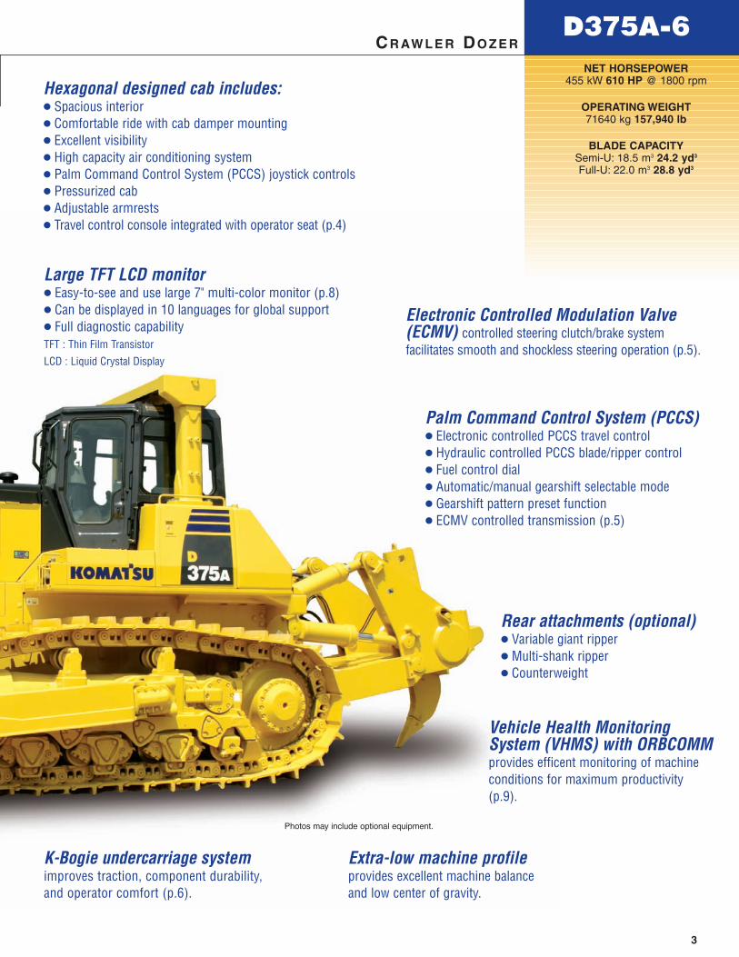
Hexagonal designed cab includes:● Spacious interior● Comfortable ride with cab damper mounting● Excellent visibility● High capacity air conditioning system● Palm Command Control System (PCCS) joystick controls● Pressurized cab● Adjustable armrests● Travel control console integrated with operator seat (p.4)
Palm Command Control System (PCCS) ● Electronic controlled PCCS travel control● Hydraulic controlled PCCS blade/ripper control● Fuel control dial● Automatic/manual gearshift selectable mode● Gearshift pattern preset function● ECMV controlled transmission (p.5)
Large TFT LCD monitor ● Easy-to-see and use large 7" multi-color monitor (p.8)● Can be displayed in 10 languages for global support ● Full diagnostic capabilityTFT : Thin Film Transistor
LCD : Liquid Crystal Display
Extra-low machine profileprovides excellent machine balanceand low center of gravity.
K-Bogie undercarriage systemimproves traction, component durability,and operator comfort (p.6).
Rear attachments (optional)● Variable giant ripper● Multi-shank ripper● Counterweight
Electronic Controlled Modulation Valve(ECMV) controlled steering clutch/brake systemfacilitates smooth and shockless steering operation (p.5).
Vehicle Health MonitoringSystem (VHMS) with ORBCOMMprovides efficent monitoring of machineconditions for maximum productivity(p.9).
4
D375A-6 C R A W L E R D O Z E R
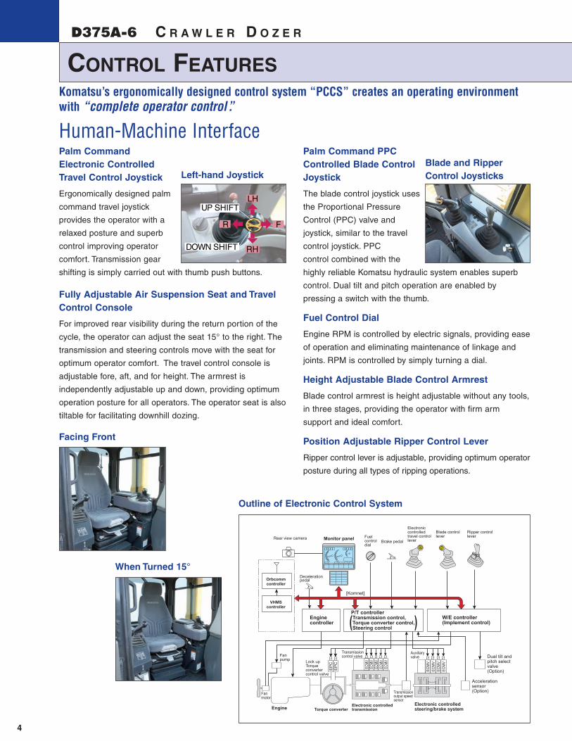
Palm Command Electronic Controlled Travel Control Joystick
Ergonomically designed palm
command travel joystick
provides the operator with a
relaxed posture and superb
control improving operator
comfort. Transmission gear
shifting is simply carried out with thumb push buttons.
Fully Adjustable Air Suspension Seat and TravelControl Console
For improved rear visibility during the return portion of the
cycle, the operator can adjust the seat 15° to the right. The
transmission and steering controls move with the seat for
optimum operator comfort. The travel control console is
adjustable fore, aft, and for height. The armrest is
independently adjustable up and down, providing optimum
operation posture for all operators. The operator seat is also
tiltable for facilitating downhill dozing.
Palm Command PPC Controlled Blade ControlJoystick
The blade control joystick uses
the Proportional Pressure
Control (PPC) valve and
joystick, similar to the travel
control joystick. PPC
control combined with the
highly reliable Komatsu hydraulic system enables superb
control. Dual tilt and pitch operation are enabled by
pressing a switch with the thumb.
Fuel Control Dial
Engine RPM is controlled by electric signals, providing ease
of operation and eliminating maintenance of linkage and
joints. RPM is controlled by simply turning a dial.
Height Adjustable Blade Control Armrest
Blade control armrest is height adjustable without any tools,
in three stages, providing the operator with firm arm
support and ideal comfort.
Position Adjustable Ripper Control Lever
Ripper control lever is adjustable, providing optimum operator
posture during all types of ripping operations.
ECMV
ECMV
ECMV
ECMV
ECMV
EP
CE
PC
[Komnet]
Electroniccontrolledtravel controllever
Blade controllever
Ripper controlleverFuel
control dial
Brake pedalMonitor panelRear view camera
Orbcommcontroller
VHMScontroller
Decelerationpedal
Transmissioncontrol valve
Enginecontroller
P/T controller Transmission control,Torque converter control,Steering control
W/E controller(Implement control)
Electronic controlledtransmissionEngine
Fanmotor
Fanpump Lock up
Torqueconvertercontrol valve
Torque converterElectronic controlledsteering/brake system
Accelerationsensor(Option)
Dual tilt andpitch selectvalve(Option)EC
MV
ECM
V
ECM
VEC
MV
Auxiliaryvalve
Transmissionoutput speedsensor
( )
Komatsu’s ergonomically designed control system “PCCS” creates an operating environmentwith “complete operator control”.
Left-hand JoystickBlade and RipperControl Joysticks
Outline of Electronic Control System
Human-Machine Interface
Facing Front
When Turned 15°
RHDOWN SHIFT
UP SHIFT
F
LH
R
CONTROL FEATURES

5
D375A-6CR AW L E R DO Z E R
Smooth Operation
The D375A-6 utilizes a highly efficient power train electronic control system. The controller registers the amount of operator
control (movements of lever and operation of switches) along with machine condition signals from each sensor to accurately
calculate the control of the torque converter, transmission, steering clutches and brakes for optimized machine operation. The
ease of operation and productivity of the new D375A-6 is greatly improved through these new features.
Electronic Controlled Modulation Valve (ECMV) Transmission
The controller automatically adjusts each clutch engagement depending on travel conditions such
as gear speed, RPM and shifting pattern. This provides shockless and smooth clutch engagement,
improved component reliability, extended component life, and operator ride comfort.
Electronic Controlled Modulation Valve (ECMV) Steering Clutches/Brakes
Sensors monitor machine operating conditions and electronically control the steering clutches and
brakes. Monitoring application parameters such as incline angle of slope and degree of load provides smooth and easy
operation by reducing counter-steering on downhill travel, etc.
Auto Downshift Function
The controller monitors engine speed and travel speed. When load
is applied and machine travel speed is reduced, the transmission
automatically downshifts to the optimum gear speed to provide
high fuel efficiency. This function provides comfortable operation
and high productivity without manual downshifting. This function
can be cancelled with the cancel switch.
Electronic Controlled Modulation Valve (ECMV)Conventional modulation valve
Time
Clut
chpr
essu
re
Heavy Load Light Load
Actuated on HeavyLoad or Steep Slope
Preset Travel Speed Selection Function
Preset travel speed enables the operator to
select fore and aft travel speeds among four
preset patterns. When the gearshift pattern is
set to either <F1-R1>, <F1-R2>, <F2-R2> or
<F2-R3L>, in automatic gearshift mode, the
gear is automatically shifted. This function
reduces gear shifting time during repeated
round-trip operations.
When dozing and turning, ECMV automaticallycontrols stroke ratio of steering clutches and brakes depending on degree of load, enabling smooth dozing and turning.
When dozing downhill, ECMVautomatically controls steering clutchesand brakes depending on incline ofmachine or degree of load, reducingcounter-steering and producingsmooth dozing operation.
F1-R1 MODE
Automaticgearshift mode
F1-R2 MODE
F2-R2 MODE
Press DOWN switch
Press DOWN switch
Press UP switch
Press UP switch
F2-R3L MODEPress DOWN switch Press UP switch
F1-R1 MODE
Shoe slip controlmode (optional)
F1-R2 MODEPress DOWN switch Press UP switch
F1-R1 MODE
Manualgearshift mode
F1-R2 MODE
F2-R2 MODE
Press DOWN switch
Press DOWN switch
Press UP switch
Press UP switch
UP
DOWN
Effect of ECMV Steering Clutches/Brake Control
Power Train Electronic Control System

PRODUCTIVITY FEATURES
D375A-6
6
C R A W L E R D O Z E R
Komatsu’s "ecot3" engines are
designed to deliver optimum
performance under the
toughest of conditions, while
meeting the most stringent
environmental regulations. This engine is EPA Tier 3,
EU Stage 3A and Japan emissions certified; "ecot3" - ecology
and economy combine with Komatsu technology to create a
high performance engine without sacrificing power or
productivity.
Engine
The Komatsu SAA6D170E-5 engine delivers a net output of
455 kW 610 HP at 1800 rpm. The fuel-efficient Komatsu
engine, together with the heavy machine weight, make the
D375A-6 a superior crawler dozer in both ripping and
dozing production. The engine is EPA Tier 3 and EU stage
3A emissions certified, and features direct fuel injection,
turbocharger, air-to-air aftercooler and cooled EGR system to
maximize fuel efficiency. To minimize noise and vibration, the
engine is mounted to the main frame with rubber cushions.
Hydraulically Driven Radiator Cooling Fan
Fan rotation is automatically controlled depending on coolant
and hydraulic oil temperatures, saving fuel and providing
increased productivity with a quiet operating environment.
Automatic Torque Converter Lockup System
For greater efficiency during long pushes, the lockup mode
allows the system to automatically engage the torque
converter lockup clutch. Locking up the torque converter
transmits all the engine power directly to the transmission,
increasing ground speed and thus achieving efficiencies equal
to a direct drive. The results of this efficient use of engine
power are less fuel consumption and faster cycle times.
(Manual gearshift mode is selectable with a switch)
K-Bogie Undercarriage System
K-Bogies with front and rear single bogies are utilized to
increase the length of track on ground improving machine
stability and leveling performance. An oscillating idler and
increased sprocket lead angle improve riding comfort when
traveling over rough terrain. K-Bogies oscillate with two
fulcrums assuring a large amount of track roller vertical travel.
Impact load to undercarriage components is minimized and
durability of components is improved since track rollers are
always in contact with track links. Track rollers follow track link
movement to extend the undercarriage life. Excellent riding
comfort is provided due to less vibration and shock when
traveling over rough terrain.
High Efficiency Blade
Capacities of 18.5 m3 24.2 yd3 (Semi-U dozer) and 22.0 m3
28.8 yd3 (U dozer) yield outstanding production. High-
tensile-strength steel comprising the front and sides of the
blade increase durability. A new blade profile features high
load hauling efficiency to maximize productivity. The blade
section profile has been changed to equal that of the next
class size dozer and the height of the blade shoulder has
been increased to reduce spillage. This increases the amount
of hold soil the blade is capable of carrying. Improved end
bits provide better penetration and extended wear life.
Dual Tilt Dozer
The dual tilt dozer increases productivity while reducing
operator effort. Optimum blade cutting angle for all types of
materials and grades can be selected on-the-go for
increased load and production. Digging, hauling, and
dumping are smooth and easy with less operator fatigue.
Dozer tilt angle and tilt speed are twice that of a conventional
single tilt system.
Fulcrum of major bogie
Fulcrum of minor bogie
Torque converter
Engine Transmission
Lockup “ON”
Lockup “OFF”

D375A-6
7
CR AW L E R DO Z E R
7
Rippers
The variable giant ripper is a parallelogram single shank ripper ideal for ripping toughmaterial. The ripping angle is variable, and the depth is adjustable in three stages by ahydraulically controlled pin puller. The variable giant ripper features a long sprocket center-to-ripper point distance, making ripping operation easy and effective while maintaining highpenetration force. The multi-shank ripper is a hydraulically controlled parallelogram ripperwith three shanks
Manual gearshift mode screen
Automatic gearshift mode screen
Gearshift modeselector switch
Working modeselector switch
Shoe slip control mode screen
Track Shoe Slip Control Mode
Eliminates the need for the operator to constantly control engine power output with the decelerator pedal while rippingsubstantially reducing operator fatigue. Maneuverability is improved because the operator is free to focus on the rippingapplication without having to monitor the track shoe slippage. Repair costs are significantly lowered and undercarriage life isextended with the reduction in track shoe slippage. The track shoe slip control system will contribute to lower fuel costsbecause the engine output is automatically controlled to optimum levels for operation.
Automatic/Manual Gearshift and Shoe Slip Control
Automatic or manual gearshift modes can be easily selected to suit the work at hand by simply pressing the switch on the multi-
monitor. (The mode can be selected when the travel control joystick is at NEUTRAL.)
Automatic gearshift mode
The mode for general dozing. When a load is applied, the gear automatically shifts down, and when the load is off, it
automatically shifts up to a set maximum gear speed. This mode economizes both fuel and production where the torque
converter lockup mechanism is actuated according to load, automatically selecting the optimum gear speed.
Manual gearshift mode
The mode for dozing and ripping rough ground. When loaded, the gear automatically shifts down, but does not shift up when
the load is off.
Working Mode
This mode can be set to either “P mode” for maximum production (power) or “E mode” for energy saving operation (economy).
Combined with the automatic gearshift mode or manual gearshift mode, the working mode allows the operator to select the
optimum machine operating condition for the work at hand. (The mode can be switched during operation.)
P mode
E mode

WORKING ENVIRONMENT
D375A-6
8
C R A W L E R D O Z E R
Hexagonal Pressurized Cab
The cab’s hexagonal design and large tinted glass windows
provide excellent front, side and rear visibility. Air filters and a
higher internal air pressure combine to help prevent dust
from entering the cab.
Fresh Air Intake from Rear of Engine Hood
The air conditioner air intake port is located at the rear of the
engine hood where there is minimal dust. The cleaning
interval of the filter is greatly extended, and use of a new
structure filter element facilitates cleaning and replacement.
Large Multi-lingual LCD Color Monitor
A new large user-friendly color monitor enables accurate and
smooth work. Improved screen visibility is achieved by the
use of a Thin Film Transistor (TFT) liquid crystal display that
can easily be read at various angles and lighting conditions.
Simple and easy to operate switches. Function keys facilitate
multi-function operations. Capable of displaying data in 10
languages to globally support operators around the world.
Comfortable Ride with Cab Damper Mounting and K-Bogie Undercarriage
The D375A-6’s cab mount uses a cab damper
mounting which provides excellent shock and vibration
absorption capacity with its long stroke. The cab damper
mounting, combined with the K-bogie undercarriage,
softens shocks and vibrations while traveling over adverse
conditions. This is otherwise impossible to absorb with
conventional cab mounting methods. The soft spring cab
damper isolates the cab from the machine body,
suppressing vibrations and providing a quiet, comfortable
operating environment.
Simple, Durable Hydraulic System
Utilizing a variable piston pump and Closed-center Load
Sensing System (CLSS), the hydraulic system has been
greatly simplified. The variable piston pump successfully
applies hydraulic power as needed to the blade and ripper.
The amount of serviceable parts and opportunity for
additional maintenance or failures are greatly reduced.
Photo may include optional equipment.
Extra switches
Basic operation switches
Function switches
Indicators
Rubber
Silicone Oil
Spring
Rubber Boot
Cab Damper Mounting
Photo may include optional equipment.

D375A-6
9
CR AW L E R DO Z E R
EASY MAINTENANCE
Preventative MaintenancePreventative maintenance is the only way to ensure long service life from your equipment. That’s why Komatsu designed the
D375A-6 with conveniently located maintenance points to make necessary inspections and maintenance quick and easy.
Low Maintenance CostsTrack Link with Wedge Ring
New D375A-6 track links featurereduced press-fit force and awedge ring. Conventional trackpins are retained only with a largepress-fit force. (The new track linkdivides pin forces between thewedge ring and press-fit force.)This enables easier service withreduced pin damage when turningpins and bushings. The result isimproved undercarriage life and reduced maintenance costthrough reduced wear, greater pin reusability, and reducedmaintenance man-hours.
Modular Power Train Design
Power train components are sealed in a modular design that allows the components to be removed and replacedwithout oil spillage, making servicing work clean, smooth,and easy.
Highly Reliable Electric Circuits
The electrical circuit reliability is increased by utilizing dust,vibration and corrosion resistant "DT connectors". Thereinforced electrical wiring harnesses include circuitbreakers and are covered with a heat-resistant material toincrease mechanical strength, provide longer life, andprotect the system from damage.
Flat Face O-ring Seals
Flat face O-ring seals are used to securely seal all hydraulic hose connections.
Enclosed Hydraulic Piping
Hydraulic piping for the blade tilt cylinder is completelyhoused in the push arm protecting it from damage.
Maintenance-Free Disc Brakes
Wet disc brakes are adjustment free and provide excellentservice life.
Wedge ring
Pin press fitting force +wedge ring holding force
Track guiding guard
Multi-Monitor with Self-Diagnostic Function
Various meters, gauges, and warning functions are centrallyarranged on the multi-monitor. This offers ease of start-upinspection and promptly warns the operator with a lamp andbuzzer if any abnormalities should occur. In addition,countermeasures are indicated in 4-stage codes to helpprevent the machine from incurring major problems.Replacement times for oil and filters are also indicated.
Oil Pressure Checking Ports
Pressure checking ports for power train components arecentralized to promote quick and simple diagnosis.
Centralized Service Station
To ensure convenient maintenance, the transmission and torque converter oil filters are both arranged next to the power train oil level gauge.
Enlarged Engine Compartment
Engine compartment space is enlarged by increased engine hood height, facilitating maintenance of the engine and related equipment. Solid engine hood prevents dust and rain from entering and helps keeps the engine clean.
Gull-Wing Engine Side Covers
Dual insulated gull-wing engine side covers facilitate enginemaintenance and filter replacement. Side covers are thicktwo-piece structures with bolt-on latches to improve durabilityand repairability.
Vehicle Health Monitoring System (VHMS)
VHMS with ORBCOMM and MyKomatsu.com service arestandard. VHMS monitors the health conditions of majorcomponents and enables remote analysis of the machine andits operation. This contributes to reduced repair costs andmaximum availability that results from proactive service.
Maintenance warning screen
Abnormality warning screen Maintenance List screen forreplacement time display

MINING SPECIFICATIONS FOR EASY MAINTENANCE
D375A-6 C R A W L E R D O Z E R
High Mounted Headlights
Illuminate the places in front of the
machine more effectively. Use of optional
HID lamps further improves visibility.
Uninterrupted Power Source
Uninterrupted power source allows for 2-way radio
communication at any time. (Interior lights can be turned on
with the starting switch at OFF position.)
Access Lights
Access lights are installed at the front
(2, right and left) and (1) at the rear of
the machine.
Work Light for the Engine Compartment
A work light is installed inside the
engine hood (left side) to facilitate
night-time inspection and maintenance.
Isolator Box
Battery and starting motor isolators are housed in the isolator
box on the left side of the machine to facilitate cut-off of the
battery circuit for maintenance of the
machine. Jump-start connectors are also
provided in the box in case of power
failure.
A : Starter isolator B : Battery isolator
C : Jump start receptacle
Rear View Camera
Improves rear visibility and is easily
viewable on the multi-monitor.
Machine is capable of mounting
3 external cameras.
Manual Engine ShutdownSwitches
In case of urgent need to stop the
engine, two shutdown switches are
provided, in the cab and at the right
rear of the machine.
Provision for Platforms
Provision for platforms eliminates the need to modify the
machine for future installation of platforms.
Platforms with Handrails andFoot Barriers
Optional platforms can be ordered to
give access to the side faces and the
rear of the machine.
Canister-type Breathers
Canister-type breathers are remotely
arranged inside the left exterior cover to
facilitate check and cleaning of the
breather of each component.
A : Power train case B : Flywheel housing
C : Damper case
Maintenance Service Center
Couplings (made by Wiggins)
installed at the rear left of the
machine enable quick drain and
change of oil and coolant. The Fast
Fuel fill (also by Wiggins) enables refueling from ground level.
The service center eliminates the need to get on/off the
machine and to remove/install covers to perform fluid
maintenance.
A : Engine oil B : Radiator coolant
C : Transmission oil D : Hydraulic oil E: Fast Fuel Fill
Concentrated Sampling Points
Concentrated sampling points are
remotely arranged in the tool box
storage area to facilitate sampling of
the oil and coolant from each
component.
A : Engine oil B : Radiator coolant
C : Transmission oil D : Hydraulic oil
ABC
BACD
BDAC
Rear view camera
Switch location (at the rear)
A
B
C
New mining specifications available on serial number 60006 and above.
10
E
Centralized Grease Points forBlade Cylinder Yoke andRipper Mount Pin
Centralized grease points enable
lubrication of both blade and ripper
from ground level.
Switch location (inside the cab)

SPECIFICATIONS
STEERING SYSTEM
PCCS, joystick controlled, wet multiple-disc steering clutches arespring-loaded and hydraulically released. Wet multiple-disc,pedal/lever controlled steering brakes are spring-actuatedhydraulically released and require no adjustment. Steering clutchesand brakes are interconnected for easy, responsive steering.
Minimum turning radius . . . . . . . . . . . . . . . . . . . . . . . . . . . 4.2 m 13'9"
UNDERCARRIAGE
Suspension . . . . . . . . . . . . . . Oscillating equalizer bar and pivot shaftTrack roller frame . . . . . . . . . . . . . . . Cylindrical, high-tensile-strength
steel constructionRollers and idlers . . . . . . . . . . . . . . . . . . . . . . . Lubricated track rollers
K-Bogie undercarriageLubricated track rollers are resiliently mounted to the track frame with a bogie suspension system whose oscillating motionis cushioned by rubber pads.
Extreme service track shoesLubricated tracks. Unique seals prevent entry of foreign abrasives into pin to bushing clearances to provide extendedservice life. Track tension is easily adjusted with grease gun.
Number of shoes (each side) . . . . . . . . . . . . . . . . . . . . . . . . . . . . . . 41Grouser height:
Single grouser . . . . . . . . . . . . . . . . . . . . . . . . . . . . . . . . 93 mm 3.7"Shoe width (standard) . . . . . . . . . . . . . . . . . . . . . . . . . . . 610 mm 24"Ground contact area . . . . . . . . . . . . . . . . . . . . . . 48560 cm2 7,527 in2
Ground pressure (tractor) . . . . . . . . . . . 108 kPa 1.10 kg/cm2 15.6 psiNumber of track rollers . . . . . . . . . . . . . . . . . . . . . . . . . . . . . . . . . . . . 8Number of carrier rollers. . . . . . . . . . . . . . . . . . . . . . . . . . . . . . . . . . . 2
COOLANT AND LUBRICANT
CAPACITY (REFILL)
Fuel tank . . . . . . . . . . . . . . . . . . . . . . . . . . . . . 1200 ltr 317.0 U.S. galCoolant . . . . . . . . . . . . . . . . . . . . . . . . . . . . . . . 120 ltr 31.7 U.S. galEngine . . . . . . . . . . . . . . . . . . . . . . . . . . . . . . . . . 86 ltr 22.7 U.S. galTorque converter, transmission,
bevel gear, and steering system . . . . . . . . . 150 ltr 39.6 U.S. galFinal drive (each side) . . . . . . . . . . . . . . . . . . . . 65 ltr 17.1 U.S. gal
Extreme Additional Ground Groundservice shoes weight contact area pressure
610 mm 0 kg 48560 cm2145 kPa
1.48 kgf/cm224" 0 lb 7,527 in2
21.0 psi
710 mm 680 kg 56520 cm2126 kPa
1.28 kgf/cm228" 1,500 lb 8,760 in2
18.2 psi
810 mm 1360 kg 64480 cm2111 kPa
1.13 kgf/cm232" 3,000 lb 9,990 in2
16.0 psi
ENGINE
Model . . . . . . . . . . . . . . . . . . . . . . . . . . . . . . Komatsu SAA6D170E-5*Type. . . . . . . . . . . . . . . . . . . . . . 4-cycle, water-cooled, direct injectionAspiration . . . . . . . . Turbocharged, air-to-air aftercooled, cooled EGRNumber of cylinders . . . . . . . . . . . . . . . . . . . . . . . . . . . . . . . . . . . . . . 6 Bore x stroke . . . . . . . . . . . . . . . . . . 170 mm x 170 mm 6.69" x 6.69"Piston displacement . . . . . . . . . . . . . . . . . . . . . . . . 23.15 ltr 1,413 in3
Governor . . . . . . . . . . . . . . . . . . . All-speed and mid-range, electronicHorsepower
SAE J1995 . . . . . . . . . . . . . . . . . . . . . . . . . . Gross 474 kW 636 HPISO 9249 / SAE J1349 . . . . . . . . . . . . . . . . . . Net 455 kW 610 HPHydraulic fan at maximum speed . . . . . . . . . . Net 433 kW 580 HPRated rpm . . . . . . . . . . . . . . . . . . . . . . . . . . . . . . . . . . . . . 1800 rpm
Fan drive type . . . . . . . . . . . . . . . . . . . . . . . . . . . . . . . . . . . . HydraulicLubrication system
Method . . . . . . . . . . . . . . . . . . . . . . . . Gear pump, force lubricationFilter . . . . . . . . . . . . . . . . . . . . . . . . . . . . . . . . . . . . . . . . . . Full-flow
* EPA Tier 3 and EU Stage 3A emissions certified.
TORQFLOW TRANSMISSION
Komatsu TORQFLOW transmission consists of a water-cooled, 3-element, 1-stage, 1-phase torque converter with lockup clutch and a planetary gear, multiple-disc clutch transmission which ishydraulically actuated and force-lubricated for optimum heatdissipation. Gearshift lock lever and neutral safety switch helpprevent accidental starts.
FINAL DRIVES
Double-reduction final drive of spur and planetary gear sets toincrease tractive effort and reduce gear tooth stresses for long finaldrive life. Segmented sprocket teeth are bolt-on for easy replacement.
Gear Forward Reverse
1st 3.5 km/h 2.2 mph 4.6 km/h 2.9 mph
2nd 6.8 km/h 4.2 mph 8.9 km/h 5.5 mph
3rd L 8.0 km/h 5.0 mph 9.7 km/h 6.0 mph
3rd 11.8 km/h 7.3 mph 15.8 km/h 9.8 mph
70
80
90
100
110
60
50
40
30
20
10
00 2 4 6 8 10 12 14 km/h
120 tonkN
400
500
600
300
200
100
0
700
800
900
1000
1100
0 1 2 3 4 5 6 87 mph
70
60
50
40
30
20
10
0
US ton
80
90
100
110
130
120
Travel Speed
Dra
wba
rPul
l
F1
F1
F2
F3L
F2
F3
F3
Manual gearshift mode
Automatic gearshift mode
D375A-6Power Shift
DRAWBAR PULL VS. SPEEDMAXIMUM USABLE PULL
DEPENDS ON TRACTION ANDWEIGHT OF TRACTORINCLUDING MOUNTED
EQUIPMENT
11
** Ground pressure based on tractor, Semi-U tilt dozer, giant ripper, cab,ROPS, operator, standard equipment, rated capacity of lubricant, coolant, andfull fuel tank.
**

G
J
I
HF
EBA
C
D
G.L
DOZER EQUIPMENT
Blade capacities are based on the SAE recommended practice J1265.
*Ground pressure shows tractor with cab, ROPS, variable giant ripper, standard equipment and applicable blade.
DIMENSIONS
SEMI-U DOZER WITH GIANT RIPPER
OPERATING WEIGHT
Tractor weight . . . . . . . . . . . . . . . . . . . . . . . . . . . 53200 kg 117,290 lbIncluding rated capacity of lubricant, coolant, full fuel tank,operator, and standard equipment.
Operating weight . . . . . . . . . . . . . . . . . . . . . . . . . 71640 kg 157,940 lbIncluding Semi-U tilt dozer, giant ripper, cab, ROPS, operator, standard equipment, rated capacity of lubricant, coolant, and full fuel tank.
Ground pressure. . . . . . . . . . . . . . . . . . 145 kPa 1.48 kg/cm2 21.0 psi
HYDRAULIC SYSTEM
Hydraulic control unit:Closed-center load sensing system (CLSS) designed for precise andresponsive control, and for efficient simultaneous operation.
Hydraulic control unit:All spool control valves externally mounted beside the hydraulic tank.Variable piston pump with capacity (discharge flow) of 366 ltr/min 96.7 U.S. gal/min for implement at rated engine rpm.Relief valve setting . . . for implement 27.5 MPa 280 kg/cm2 3,980 psi
Control valves:Spool control valves for Semi-U tilt dozer and Full-U tilt dozer.
Positions: Blade lift. . . . . . . . . . . . . . . . Raise, hold, lower, and floatBlade tilt . . . . . . . . . . . . . . . . . . . . . . Right, hold, and left
Additional control valve required for variable digging angle multi-shank ripper and giant ripper.
Positions: Ripper lift . . . . . . . . . . . . . . . . . . . Raise, hold, and lowerRipper tilt . . . . . . . . . . . . . . Increase, hold, and decrease
Hydraulic cylinders . . . . . . . . . . . . . . . . . . . . . . . Double-acting, piston
Hydraulic oil capacity (refill):Semi-U dozer or U dozer. . . . . . . . . . . . . . . . 130 ltr 34.4 U.S. gal
Ripper equipment (additional volume):Giant ripper (variable) . . . . . . . . . . . . . . . . . . . 45 ltr 11.9 U.S. galMulti-shank ripper (variable) . . . . . . . . . . . . . . 45 ltr 11.9 U.S. gal
Number of cylinders Bore
Blade lift 2 140 mm 5.5"
Blade tilt 1 180 mm 7.1"
Ripper lift 2 200 mm 7.9"
Ripper tilt 2 180 mm 7.1"
A 2500 mm 8'2"
B 4695 mm 15'5"
C 4265 mm 14'0"
D 2265 mm 7'5"
E 3980 mm 13'1"
F 10485 mm 34'5"
G 3460 mm 11'4"
H 1485 mm 4'10"
I 1100 mm 3'7"
J 4285 mm 14'1"
Ground Clearance: 610 mm 2'0"
Overall Blade Maximum Maximum Maximum Weightlength with Blade length x height lift above drop below tilt Dozer Hydraulic Ground
dozer capacity (with spill guard height) ground ground adjustment equipment oil Pressure*
Strengthened 146 kPaDual tilt 7780 mm 18.5 m3 4695 mm x 2265 mm 1690 mm 735 mm 1185 mm 11570 kg 50 kg 1.49 kgf/cm2
Semi-U dozer 25'6" 24.2 yd3 15'5" x 7'5" 5'7" 2'5" 3'11" 25,510 lb 110 lb 21.2 psiStrengthened 148 kPadual tilt U dozer 8140 mm 22.0 m3 5140 mm x 2265 mm (2525 mm) 1690 mm 735 mm 1300 mm 12600 kg 50 kg 1.51 kgf/cm2
with spill guard 26'8" 28.8 yd3 16'10" x 7'5" (8'3") 5'7" 2'5" 4'3" 27,780 lb 110 lb21.4 psi
12
CR AW L E R DO Z E RD375A-6

13
D375A-6CR AW L E R DO Z E R
OPTIONAL EQUIPMENT
STANDARD EQUIPMENT FOR BASE MACHINE
Variable giant ripper:Variable, parallelogram single-shank ripperideal for ripping up tough material. Rippingangle is variable. Ripping depth is adjustablein three stages by a hydraulically controlledpin puller.
Weight (including hydraulic control unit and oil) . . . 6200 kg 13,670 lb
Beam length. . . . . . . . . . . . . . 1453 mm 4'9"Maximum lift above ground . . 1100 mm 3'7"Maximum digging depth . . . 1485 mm 4'10"
Multi-shank ripper:Hydraulically controlled parallelogram ripperwith three shanks. Ripping angle issteplessly adjustable.
Weight (including hydraulic control unit and oil) . . . 6800 kg 14,900 lb
Beam length. . . . . . . . . . . . . . 2910 mm 9'7"Maximum lift above ground . . 1135 mm 3'9"Maximum digging depth . . . . 1140 mm 3'9"
l Accessory sockets, 2x12V 3 Additional front and rear work lights l Air conditioner with heater and defroster l Alternator, 90 ampere/24V l Back-up alarml Batteries, 2x12V, 200 Ah 3 Batteries and starter isolator boxl Blower Cooling Fan3 Cab light uninterrupted power sourcel Stereo 3 Canister-type breathers 3 Centralized grease points,
ripper mount pin 3 Centralized grease points,
blade cylinder yoke 3 Concentrated sampling points for oil
and coolant l Decelerator pedal l Dry-type air cleaner with dust evacuator
and dust indicator l Dual tilt dozer l Eight-roller track frames3 Engine Prelube 3 Evacuation service center for oil
and coolant 3 Fast fuel fill l Final drive case wear guard 3 High mounted headlights l Hinged front mask l Hinged underguard with front pull hook
l Hydraulics for ripper l Hydraulic track adjustersl K-Bogie Undercarriage Systeml Lockup torque converterl Lunchbox holder3 Manual engine stop switches l Mirror, rearviewl Monitor, large multi-color TFT LCD
with self-diagnostic functionl Muffler with rain cap l PCCS palm lever steering control l Perforated side covers3 Provision for platforms l Radiator reserve tank3 Rear view cameral ROPS/FOPS Level 2l Seat belt, 78mm 3" l Seat, air suspension, fabric, high back,
fully adjustablel Shoes, 610 mm 24" extreme service,
single grouserl Segmented sprockets l Spill guard for Full U dozer l Starting motors, 2 x 7.5 kW/24V l Steps, heavy-duty and handlesl Sun visor l TORQFLOW transmission l Track roller guards
l Track shoe slip control systeml VHMS with ORBCOMMl Vandalism protection kitl Warning hornl Wet steering clutches3 Working light for the engine compartment
ROPS:*Weight . . . . . . . . . . . . . . . . . 700 kg 1,540 lbRoof dimensions:
Width . . . . . . . . . . . . . . . . . 1980 mm 6'6"Height from compartment floor . . . . . . . . . 1872 mm 6'2"
Steel cab:*Weight . . . . . . . . . . . . . . . . . 570 kg 1,260 lbDimensions:
Length . . . . . . . . . . . . . . . . 1875 mm 6'2"Width . . . . . . . . . . . . . . . . . 1740 mm 5'9"
Height from compartment floor to ceiling . . . . . . . . . . 1630 mm 5'4"
*ROPS is included in the base machine.ROPS/FOPS meet all OSHA/MSHA standardsand regulations criteria.FOPS Level 2
Dozer assembly and rear-mounted equipment arenot included in base machine.
l Standard on S/N 60001 and beyond3 Additionally standard on S/N 60006 and beyond
l Counterweightl Cushion push block 3 HID work lights l Hitch l Panel cover3 Platform, LH side only
3 Platforms with handrails and foot barriers l Pusher plate l Spill guard for Semi-U dozer l Shoes:
— 710 mm 28" — 810 mm 32"
l Strengthed Semi-U bladel Strengthed Full U blade
l Optional on S/N 60001 and beyond3 Additional options on S/N 60006 and beyond
Note: ProVision High Precision GPS grade level system available from Modular Mining

www.KomatsuAmerica.com Komatsu America Corp. is an authorized licensee of Komatsu Ltd.Materials and specifications are subject to change without notice
is a registered trademark of Komatsu Ltd., Japan
AESS800-00 ©2009 Komatsu America Corp. Printed in USA D10(2.5M)CCI 10/09 (EV-1)