d2.1 - definition of use cases and scenarios for safe ... · pdf filedefinition of use cases...
TRANSCRIPT

Project Acronym: SafeAdapt
Project Title: Safe Adaptive Software for Fully Electric Vehicles
Grant Agreement Number: 608945
Coordinator: Dr.-Ing. Dirk Eilers
Funding Scheme: FP7-2013-ICT-GC
Deliverable 2.1
Definition of Use Cases and Scenarios for Safe Adaptation
Due date of deliverable: 30. April 2014
Actual submission Date: 19. Mai 2014
Lead beneficiary for this deliverable: TECNALIA
Dissemination level
PU Public X PP Restricted to other programme participants (including the Commission Services) RE Restricted to a group specified by the consortium (including the Commission Services) CO Confidential, only for members of the consortium (including the Commission Services)
The research leading to these results has received funding from the European Community's Seventh Framework Programme (FP7/2007-2013)
This document contains information which is proprietary to the members of the SafeAdapt consortium. Neither this document nor the information contained herein shall be used, duplicated or communicated by any means to any third party, in whole or in parts, except with prior written consent of the member of the SafeAdapt consortium.

D2.1 Definition of use cases and scenarios for safe adaptation
2
Document Information
Title Definition of use cases and scenarios for safe adaptation
Creator TECNALIA
Description This document describes the different use cases and scenarios of interest for the SafeAdapt project
Publisher TECNALIA
Contributors Alejandra Ruiz (TECNALIA)
Mª Carmen Palacios (TECNALIA)
Maite Álvarez (TECNALIA)
Thorsten Rosenthal (DELPHI)
Timo Feismann (DELPHI)
Ken Lam (DURACAR)
Andrea Saccagno (FICOSA)
Gereon Weiss (FRAUNHOFER)
Marc Zeller (FRAUNHOFER)
Francesco Iennaro (PININFARINA)
Cornel Klein (SIEMENS)
Michael Armbruster (SIEMENS)
Andreas Eckel (TTTECH)
Tudor Ionescu (TTTECH)
Revision: Ansgar Radermacher (CEA), Önder Gürcan (CEA), and Philipp Schleiss (FRAUNHOFER)
Language en-GB
Creation date 30/09/2013
Version number 1.0
Version date 19. Mai 2014
Audience internal
public
restricted
D2.1 Definition of use cases and scenarios for safe adaptation
3
Table of Contents
List of Figures 4 List of Tables 5 Executive Summary 6 1 Introduction 7
1.1. Document Scope 7 1.2. Document Outline 8
2 Terms and Definitions 9
2.1. General Concepts 9 2.2. Items Status 11 2.3. E/E Architecture Fundamentals 11
3 Method of Investigation 14
3.1. Process of Definition and Selection 14 3.2. Components, Items & Vehicles 15 3.3. Hazard Analysis and Risk Assessment 16 3.4. Use Case Template 21 3.5. Use Cases List and Overview 23
4 Selected Use Cases 24
4.1. Reconfigure of Failed Cruise Control (Cold-Standby) 24 4.2. Steer-By-Wire Adaptation after ECU-Failure (CSCC-Failover) 26 4.3. Adaptation after Break-by-Wire Malfunction (Dependable Function) 27 4.4. Communication Failure with External Aggregate (Hot-Standby) 29 4.5. Installation of New Component (New) 31 4.6. Update of Function (Update) 33 4.7. Degradation of Steer-By-Wire Application (Internal) 36 4.8. Adaptation for Range Extension (Energy Efficiency) 38
5 Configurations 40
5.1. VSIEMENS Configuration 40 5.2. DYNACAR Configuration 42
5.2.1. DYNACAR Overview 42 5.2.2. DYNACAR RT 44 5.2.3. System Requirements of DYNACAR 44 5.2.4. DYNACAR and SafeAdapt Use Cases 46
6 Conclusions 47 Bibliography 49 List of Abbreviations 50

D2.1 Definition of use cases and scenarios for safe adaptation
4
List of Figures
Figure 1: Hierarchy of the Vehicle Concepts .................................................................................... 9 Figure 2: Hardware Architecture .................................................................................................... 12 Figure 3: Software Architecture ...................................................................................................... 13 Figure 4: The RACE Demonstrator Car ......................................................................................... 40 Figure 5: Redundant Power Supply, Computation & Communication of RACE Car ...................... 41 Figure 6: Schematic DYNACAR RT Solution with Software and Hardware Definition ................... 42 Figure 7: Roll Stiffness Model and 3D Model of Test Vehicle ........................................................ 43 Figure 8: Graphic Engine with the Test Vehicle for Dynamic Model Validation on Real Circuit ..... 43 Figure 9: Example of DYNACAR RT Configuration ....................................................................... 44 Figure 10: DYNACAR RT Implementation Scheme ....................................................................... 45 Figure 11: Immersive Configuration with Three Screens and Two Graphic Cards ........................ 45 Figure 12: NI-PXI 8110 RT hardware ............................................................................................. 46

D2.1 Definition of use cases and scenarios for safe adaptation
5
List of Tables
Table 1 Hazard Analysis and Risk Assessment Extract ................................................................. 20 Table 2 Use Case & Scenario Template ........................................................................................ 21

D2.1 Definition of use cases and scenarios for safe adaptation
6
Executive Summary
This document defines use cases and scenarios and their high-level design and safety adaptation requirements that are necessary for successfully achieving the SafeAdapt project objectives. In addition, SafeAdapt’s expected impact on safety is outlined by clarifying the main adaptation capabilities of the runtime core and its ability to keep the fully electric vehicle in a safe state during hazardous situations.
This document includes:
An introduction for the Task 2.1 “Use cases and scenarios for safe adaptation” Terms and definitions needed to understand the use cases and scenarios The method used for identifying and defining use cases according to established selection
criteria and a Hazard Analysis and Risk Assessment The detailed description of the selected use cases A preliminary version of possible configurations that will be used to deploy the use cases
onto a real vehicle and onto a vehicle simulation framework

D2.1 Definition of use cases and scenarios for safe adaptation
7
1 Introduction
The promising advent of fully electric vehicles also means a shift towards fully electrical control of the vehicle functions. In particular, critical X-by-Wire functions require solutions with sophisticated redundancy. As a result, the overall Electric/Electronic (E/E) architecture of a vehicle is becoming more overly complex and costly.
The main concept behind SafeAdapt (Safe Adaptive Software for Fully Electric Vehicles) is to develop novel E/E architecture based on adaptation to achieve safety, reliability, and cost-efficiency in future FEVs. Thereby, the complexity of the system will be reduced the system through generic and system-wide fault handling and change management mechanisms. Furthermore, the reliability despite failures is extended, active safety is improved, and resource utilisation is optimised. This is especially important for increasing reliability and efficiency regarding energy consumption, cost, and design simplicity.
SafeAdapt follows a holistic approach for building adaptive systems in safety-critical environments by comprising methods and tools. The technical approach builds on a SafeAdapt Platform Core, encapsulating the basic adaptation mechanisms for re-allocating and updating functionalities in distributed automotive control systems. This is the basis for an interoperable and standardised solution for adaptation and fault handling in AUTOSAR. Although SafeAdapt does not endeavour to certify developed software or hardware, as the certification process exceeds the scope of project. However, the SafeAdapt approach considers functional safety with respect to the ISO 26262 standard to support the certification of safety-critical e-vehicle systems.
SafeAdapt provides an integrated approach for engineering such adaptive, complex and safe systems, ranging from tool chain support, reference architectures, modelling of system design and networking, up to early validation and verification. For realistic validation of the adaptation and redundancy concepts, an actual vehicle prototype with different and partially redundant applications is developed.
1.1. Document Scope
The purpose of this document is to identify and outline the most representative use cases and context scenarios in the automotive domain where different failure situations arise regarding ECUs, sensors, and actuators as well as software components (i.e., software failures). These use cases and scenarios consist of a set of electrically controlled vehicle functions that are candidates for adaptation (i.e., reconfiguration during runtime) according to different operational conditions (e.g., type of road, velocity, or driver’s alertness).
The use cases and scenarios are defined to demonstrate the adaptation capabilities of the SafeAdapt runtime core and its ability to keep the vehicle in an overall safe state regardless of failure scenario. As these use cases and scenarios are provided in an early stage of the project, they will be influence both in the specification and development phase and furthermore affected through integration and Verification and Validation (V&V) of the prototype e-vehicle. Consequently, this initial version will be updated during the course of the project depending on first experimental results and the evolution of case studies.
D2.1 Definition of use cases and scenarios for safe adaptation
8
1.2. Document Outline
The remainder of the report is structured as follows:
• Section 2 includes terms and definitions that provide the necessary background required to properly understand the concepts described in this document.
• Section 3 provides detailed insight into the methods used to identify, classify, and select the most relevant uses cases. To achieve a uniform documentation format, a use case and scenario template is defined along with a detailed explanation of the information required. In addition, a comprehensive list of use cases is provided.
• Section 4 refines the initial list provided in the previous section into a selected set of use cases. This remaining set aims to provide high-level use cases that however contain sufficient information for extracting both functional and non-functional requirements. In addition, special focus is set on safety adaption is to facilitate the development of safety case.
• Section 5 depicts the platforms (e-vehicle & simulation environment) on which the different applications will be integrated, tested and evaluated.
• Section 6 drafts a conclusion and provides outlook on future requirements and development efforts.

D2.1 Definition of use cases and scenarios for safe adaptation
9
2 Terms and Definitions
2.1. General Concepts
To prevent confusion of terms that may have different meaning depending on the area of application, an unambiguous definition is outlined, which will be used uniformly in this and all subsequent documents. Where applicable, the definitions have been extracted from the ISO 26262 document.
Figure 1: Hierarchy of the Vehicle Concepts
Architecture
Representation of the structure of the item or functions or systems or elements that allows identification of building blocks, theirboundaries and interfaces, and includes the allocation of functionsto hardware and software elements (ISO 26262)
Component-ISO
The ISO 26262 defines a Component-ISO as a non-system level element that is logically and technically separable and is comprisedof more than one hardware part or more software units. Acomponent is part of a system (see Figure 1).
Configuration Selected composition of the system to be tested, includingcomponents and engineering environment
Control factor Parameters that have to be controlled during a scenario to ensure that these factors do not disturb the comparability
Element The ISO 26262 defines an Element as a system or part of a systemincluding components, hardware, software, hardware parts, and software units (see Figure 1).
Item The ISO 26262 defines an Item as a system or array of systems toimplement a function at the vehicle level (see Figure 1).

D2.1 Definition of use cases and scenarios for safe adaptation
10
Part/Unit The ISO 26262 defines a Part/Unit as an atomic level softwarecomponent of the software architecture that can be subjected tostandalone testing (see Figure 1).
Scenario Specific driving situation which is relevant for a safety function of the regarded system
Situational variable External influence (e.g., gradient of the road, weather conditions, or traffic situations) that should be considered when defining thescenario
System
The ISO 26262 defines a System as a set of elements that relate atleast a sensor, a controller and an actuator with one another. Therelated sensor or actuator can be included in the system or can beexternal to the system. An element of a system can also be another system (see Figure 1).
Test Case Formalisation of a safety relevant driving situation which shall be used to support the claim of a correct safety function
Use Case
The behaviour of a system in a certain situation. Thus, it describes:
the objective of the Use Case
the entities that participate in the Use Case as actors
the assumptions and constraints that govern the Use Case
the circumstances in which the Use Case occurs
the circumstances in which the Use Case concludes
the sequence of the interaction between users and the system
In particular, it is important that use cases describe scenarios, tasks and procedures where applications demonstrate the adaptation capabilities of the SafeAdapt runtime core and its ability to keep thevehicle in an overall safe state regardless of failure scenario.
User
Any actor that is directly interacting with the system.
Each use case could imply various actors exhibiting various roles. Classical and well-identified roles are Driver, OEM, Tier 1, or Safety Engineer.
Validation
Process of evaluating the system impact e.g., on safety. That is,validation checks and tests whether the system "does what it was designed for“, quoted by the performance indicators (based on user needs)
Vehicle Reference to a passenger car that can be either simulated or a realvehicle (see Figure 1).
Verification
Describes the test of a system/function against its requirements
Determination of completeness and correct specification orimplementations of requirements from a phase or subphase

D2.1 Definition of use cases and scenarios for safe adaptation
11
2.2. Items Status
To establish a better understanding of the safe adaptation actions proposed in this document, the fundamental concepts required for adaptation are outlined below:
Passivation Deactivation or isolation of partitions, computing cores, …, or communication links when a failure or an error is detected in order to prevent further error propagation
Activation Transition of an application from a non-operation into a fully operational state
Reconfiguration Modified distribution of resources such as, applications, partitions, or communication links
Reallocation Redistribution of applications onto different computational resources
2.3. E/E Architecture Fundamentals
Hardware Architecture
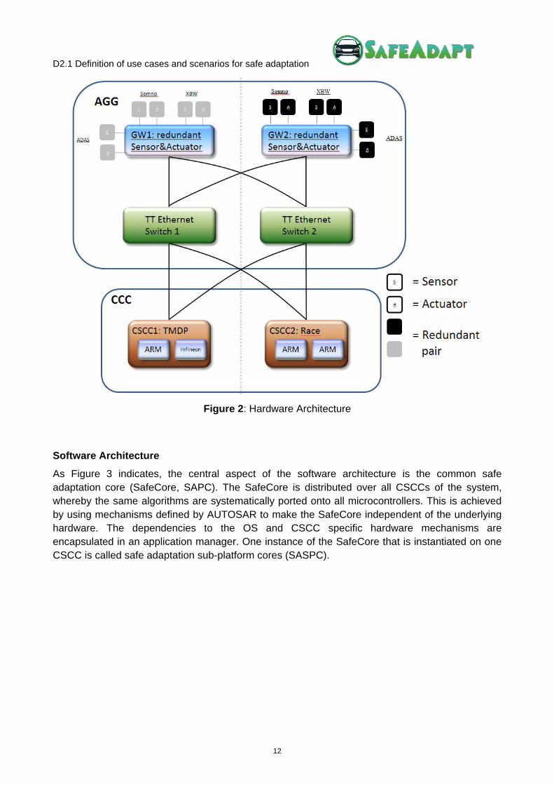
For the SafeAdapt project a “double star” network topology was selected, as such an architecture enables all information between sensors, actuators, and control units to be transported simultaneously on two independent paths.
For this purpose every sensor and actuator is connected to a gateway (GW). The duty of a gateway is to translate signals and commands from device specific communication links (e.g. CAN, analogue I/O, PWM) into messages compatible with the TTEthernet network and vice versa. The entity of sensors, actuators and switches is called aggregate ICT information and communication technology (AGG).
Another central element of this architecture are computing platforms. Compared to a state of the art architecture these platforms have notably more computing power but suffer less interference from physically connected devices, as all interaction is channelled through the network.
Such computing platforms are referred to as central ICT sub-computing cores (CSCC). The entity of all computing platforms is called central ICT computing core (CCC), as depicted in Figure 2.
D2.1 Definition of use cases and scenarios for safe adaptation
12
Figure 2: Hardware Architecture
Software Architecture
As Figure 3 indicates, the central aspect of the software architecture is the common safe adaptation core (SafeCore, SAPC). The SafeCore is distributed over all CSCCs of the system, whereby the same algorithms are systematically ported onto all microcontrollers. This is achieved by using mechanisms defined by AUTOSAR to make the SafeCore independent of the underlying hardware. The dependencies to the OS and CSCC specific hardware mechanisms are encapsulated in an application manager. One instance of the SafeCore that is instantiated on one CSCC is called safe adaptation sub-platform cores (SASPC).

D2.1 Definition of use cases and scenarios for safe adaptation
13
Figure 3: Software Architecture

D2.1 Definition of use cases and scenarios for safe adaptation
14
3 Method of Investigation
3.1. Process of Definition and Selection
As mentioned before, the objective of the SafeAdapt project is to develop a novel architecture concept based on adaptation to address the needs for safe, reliable, and cost-efficiency E/E architectures for future fully electric vehicles (FEV).
In order to guarantee that this objective is satisfied and the tasks being executed along the project are aligned with this objective, the research is oriented to identify and define the use cases and scenarios most relevant for the project. Therefore, the following steps were defined:
1. Vehicles, Items and Components Identification
To facilitate the future certification process, the different elements involved are classified according to the concepts defined in ISO 26262, that is, vehicle (passenger car), functional items and components. This classification will help to organise the elements and actors involved in the different uses cases.
2. Situations Definition
The objective will be to define different situations in which a vehicle can be successfully tested. These situations relate to possible items malfunctioning and exhibiting unintended behaviour, and will be described by operation conditions (possible factors of the environment as well as driver and vehicle status).
3. Malfunctions Identification
The ISO 26262 addresses possible hazards caused by a malfunction of a safety-critical E/E system, including interaction between such systems. Therefore, the use cases will account for these malfunctions and subsequently identify possible conditions or triggers that cause them.
4. ASIL Determination
As mentioned in ISO26262 normative, the hazard analysis and risk assessment estimates the probability of exposure, the controllability, and the severity of the hazardous events. In conjunction, these parameters determine the ASILs of the hazardous events. At this point, malfunctions will be associated with situations focusing on controllability, loss and damages, and probability of exposure. With this information, the ASIL classification will be determined. ASIL C and D will drive the use cases selection as these are at the centre of interest.
5. Use Case Definition
Subsequently, a list of possible use cases will be identified. The refinement and selection of the most relevant use case will be based on the previous ASIL classification. The use case definition will be driven by safety relevant situations, thus one or more than one item can be involved in a specific use case. The use cases are described according to the expected behaviour from a vehicle-level point of view.

D2.1 Definition of use cases and scenarios for safe adaptation
15
3.2. Components, Items & Vehicles
Components and Sensors
Name Description of functionality
RaCam (Combined Radar and Camera Module)
RaCam is a single module that is comprised of an active radar portion and a camera portion. Long-Range and Mid-Range radar scan regions are supported. The camera accepts visible light.
General Safety Board (GSB)
The General Safety Board (GSB) is endowed with a redundantTTEthernet controller and over 200 I/O pins that can beconnected to sensors, actuators, and other bus systems. GSB thus provides a suitable platform for the redundantconnections to sensors and actuators.
TTEthernet Switch
TTEthernet Switches are compatible with AVB and other automotive Ethernet protocols. They support three classesof traffic: time-triggered (will most likely be used for safety-critical functions in project), rate-constraint, and best-effort (standard Ethernet).
Delphi TMDP (Trusted Multi Domain Platform)
Multi domain controller platform which aims to consolidate functions throughout different in-vehicle domains. The SafeAdapt Platform Core will run on this hardware that is also compliant to the existing standards for functional safety in the automotive domain (ISO 26262).
RACE Platform Multi domain controller platform consisting of two control computers that perform pairwise validation of computational results on message level
Items (Applications)
ASIL Classification
Name Description of functionality Depends on
D BBW (Brake-by-Wire)
Function to control brakes through electrical means
-
D IWM (In wheel motor)
Electric motor that is incorporated into the hub of a wheel and drives it directly
-
D SBW (Steer-by-Wire)
The control of the wheels' direction will be established through electric motor(s) which are actuated by electronic control units monitoring the steering wheel inputs from the driver
-
C ACC (Adaptive Cruise Control)
System for road vehicles that automatically adjusts the vehicle speed (automatic acceleration and deceleration) to maintain a safe distance from vehicles ahead
-

D2.1 Definition of use cases and scenarios for safe adaptation
16
Items (Applications)
ASIL Classification
Name Description of functionality Depends on
C
AEB (Automatic Emergency Braking)
Automatic Emergency Braking is applied automatically by the vehicle in response to the detection of a likely collision to reduce the vehicle speed and potentially avoid the collision
BBW
A SomnoAlert
Detects driver’s fatigue and warns the driver. Uses data available from other vehicle systems, like speed, steering wheel angle, or yaw rate, turn indicator, pedals actions combined with a dedicated camera that measures the respiratory rate of the driver
-
Vehicles
Name Description of functionality
VSIEMENS Passenger car
Dynacar Virtual vehicle simulating dynamics of the car
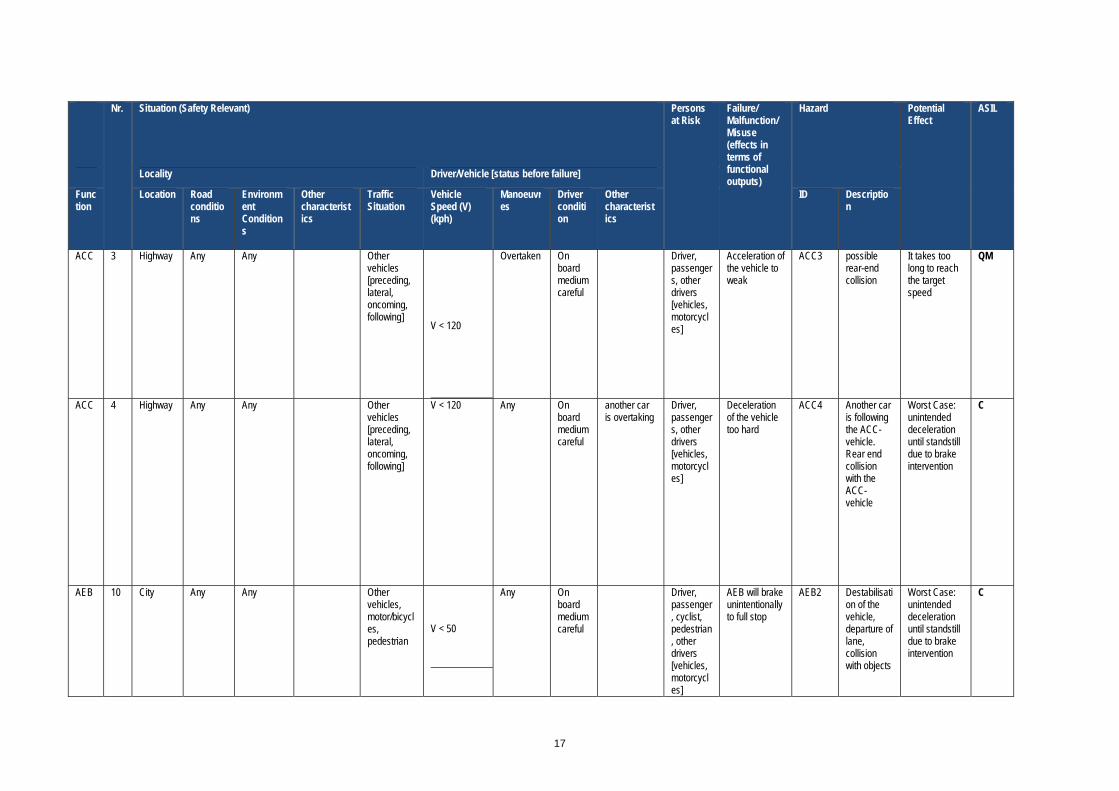
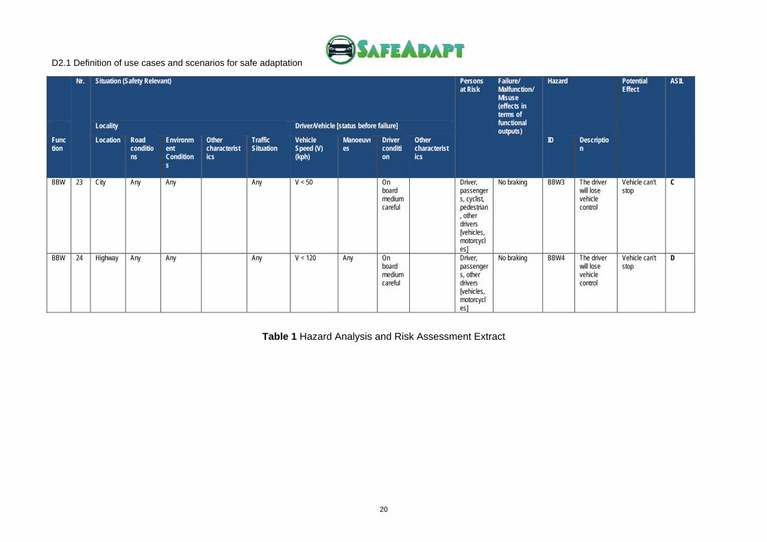
3.3. Hazard Analysis and Risk Assessment
The ISO 26262 demands an analysis of all vehicle functions by performing a Hazard Analysis and Risk Assessment (HARA). Furthermore, one aim of the SafeAdapt project is to improve controllability and hazard exposure by means of adaption in situation that may result in a hazard. Consequently, such adaptation approaches must also be validated to collect evidence to prove their correct functioning.
The previously defined list of applications from different domains within the electric vehicle are set into relation to vehicle-level functionalities and finally associated with an ASIL (Automotive Safety Integrity Level) through a mandatory HARA. The following table shows some situations to be considered in the SafeAdapt project based on the most significant hazardous event identified during HARA:
17
Nr. Situation (Safety Relevant) Persons at Risk
Failure/ Malfunction/ Misuse (effects in terms of functional outputs)
Hazard Potential Effect
ASIL
Locality Driver/Vehicle [status before failure]
Function
Location Road conditions
Environment Conditions
Other characteristics
Traffic Situation
Vehicle Speed (V) (kph)
Manoeuvres
Driver condition
Other characteristics
ID Description
ACC 3 Highway Any Any Other vehicles [preceding, lateral, oncoming, following]
V < 120
Overtaken On board medium careful
Driver, passengers, other drivers [vehicles, motorcycles]
Acceleration of the vehicle to weak
ACC3 possible rear-end collision
It takes too long to reach the target speed
QM
ACC 4 Highway Any Any Other vehicles [preceding, lateral, oncoming, following]
V < 120 Any On board medium careful
another car is overtaking
Driver, passengers, other drivers [vehicles, motorcycles]
Deceleration of the vehicle too hard
ACC4 Another car is following the ACC-vehicle. Rear end collision with the ACC-vehicle
Worst Case: unintended deceleration until standstill due to brake intervention
C
AEB 10 City Any Any Other vehicles, motor/bicycles, pedestrian
V < 50
Any On board medium careful
Driver, passenger, cyclist, pedestrian, other drivers [vehicles, motorcycles]
AEB will brake unintentionally to full stop
AEB2 Destabilisation of the vehicle, departure of lane, collision with objects
Worst Case: unintended deceleration until standstill due to brake intervention
C

D2.1 Definition of use cases and scenarios for safe adaptation
18
Nr. Situation (Safety Relevant) Persons at Risk
Failure/ Malfunction/ Misuse (effects in terms of functional outputs)
Hazard Potential Effect
ASIL
Locality Driver/Vehicle [status before failure]
Function
Location Road conditions
Environment Conditions
Other characteristics
Traffic Situation
Vehicle Speed (V) (kph)
Manoeuvres
Driver condition
Other characteristics
ID Description
BMS 13 Parking N/A N/A N/A V = 0 Parking Off board
Driver, Passengers
Unintended charging of HV-Battery from grid
BMS1 Driver and passengers can be damaged by a fire or explosion
overcharging of battery- degassing fire, explosion(depending on cell chemistry)
D
BMS 14 Parking N/A Any Other vehicles, motor/bicycles, pedestrian
V = 0 Parking Off board
At charging station(open area)
Driver, passengers, cyclist, pedestrian, other drivers [vehicles, motorcycles]
unintended charging of HV-Battery from grid
BMS2 Drivers, passengers, pedestrian can be damaged by a fire or explosion
overcharging of Battery- degassing fire, explosion(depending on cell chemistry)
C
BMS 15 Parking N/A Any Other vehicles, motor/bicycles, pedestrian
V = 0 Parking Off board
During e-braking
Driver, passengers, cyclist, pedestrian, other drivers [vehicles, motorcycles]
Unintended charging of HV-Battery from Range Extender
BMS3 Drivers, passengers, pedestrian can be damaged by a fire or explosion
overcharging of Battery- degassing fire, explosion(depending on cell chemistry), local heating due to overcurrent
C
MIW 16 Any Any Any Any V < 120 Any On board medium careful
Driver, passengers, other drivers [vehicles, motorcycles]
No acceleration/Loss of one e-motor
MIW1 The driver may (partial) lose vehicle control
C

D2.1 Definition of use cases and scenarios for safe adaptation
19
Nr. Situation (Safety Relevant) Persons at Risk
Failure/ Malfunction/ Misuse (effects in terms of functional outputs)
Hazard Potential Effect
ASIL
Locality Driver/Vehicle [status before failure]
Function
Location Road conditions
Environment Conditions
Other characteristics
Traffic Situation
Vehicle Speed (V) (kph)
Manoeuvres
Driver condition
Other characteristics
ID Description
MIW 17 Any Any Any Any V < 120 Any On board medium careful
Driver, passengers, other drivers [vehicles, motorcycles]
Unintended acceleration of one e-motor
MIW2 The driver may (partial) lose vehicle control
D
MIW 18 Any Any Any Any V < 120 Any On board medium careful
Driver, passengers, other drivers [vehicles, motorcycles]
Unintended e-braking of one e-motor
MIW3 The driver may (partial) lose vehicle control
D
SBW 19 Any Any Any Any V < 120 Any On board medium careful
Driver, passengers, other drivers [vehicles, motorcycles]
Unintended acceleration of one e-motor
SBW1 The driver may (partial) lose vehicle control
D
BBW 21 Any Any Any Any V < 120 Any On board medium careful
Driver, passengers, other drivers [vehicles, motorcycles]
Unintended e-braking of one e-motor
BBW1 The driver may (partial) lose vehicle control
D
BBW 22 Any On a curve
Any Any V < 120 Any On board medium careful
Driver, passengers, other drivers [vehicles, motorcycles]
Unintended e-braking of one e-motor
BBW2 The driver may (partial) lose vehicle control
D
D2.1 Definition of use cases and scenarios for safe adaptation
20
Nr. Situation (Safety Relevant) Persons at Risk
Failure/ Malfunction/ Misuse (effects in terms of functional outputs)
Hazard Potential Effect
ASIL
Locality Driver/Vehicle [status before failure]
Function
Location Road conditions
Environment Conditions
Other characteristics
Traffic Situation
Vehicle Speed (V) (kph)
Manoeuvres
Driver condition
Other characteristics
ID Description
BBW 23 City Any Any Any V < 50 On board medium careful
Driver, passengers, cyclist, pedestrian, other drivers [vehicles, motorcycles]
No braking BBW3 The driver will lose vehicle control
Vehicle can't stop
C
BBW 24 Highway Any Any Any V < 120 Any On board medium careful
Driver, passengers, other drivers [vehicles, motorcycles]
No braking BBW4 The driver will lose vehicle control
Vehicle can't stop
D
Table 1 Hazard Analysis and Risk Assessment Extract

D2.1 Definition of use cases and scenarios for safe adaptation
21
3.4. Use Case Template
A use case template has been defined to provide a unified and flexible format. It aims at recording high-level use case that however contain the required information to extract functional and non-functional requirements.
The following subsection describes the components of the template:
Use Case ID: XXX_UC_YY
Name: XXXXXXXX
Version 1.0
Application Domain
Author (Name/Organisation)
Involved Partners
Operational Description
Actors
Involved Components
Constraints
Pre-conditions
Trigger
Post-conditions
Basic Path/Main Flow /Main Scenario
Exception Paths/Alternate Flows / Alternate Scenario
Expected Results
High-level Design Requirements
High-level Safety Adaptation Requirements
Table 2 Use Case & Scenario Template
a) Use Case Identifier, Name and Version
These fields contain an identifier for the use case and its complete name.
b) Application Domain
Application domain concerned by the use case can be:
o Chassis
o Powertrain
o Car body
o Multimedia / HMI / Telematics
o Car Manufacturer Interest

D2.1 Definition of use cases and scenarios for safe adaptation
22
c) Author (Name/Organisation) and Involved Partners
These fields contain SafeAdapt partners involved in the execution of the use case.
d) Operational Description
This field briefly captures the operational use of involved function in the situation. In addition, relevant instructions to reach a safe state of the vehicle are described.
e) Actors
Each use case could imply various actors. Classical and well-identified roles are:
• Driver
• Vehicle owner
• OEM
• Component supplier
• Maintenance service provider
• Third Party
f) Involved Components
Any logical component (both hardware and software) involved in the implementation is depicted in this field. During the use case definition process, a detailed list of components has been defined in section “3.2 Components, Items & Vehicles”
g) Constraints
Internal vehicle configuration is described along with the definition of main variables that can have an effect on the desired behaviour of components.
h) Pre-conditions, Trigger and Post-conditions
Pre-conditions cover the operational state that the system must be in before the use case is executed due to the existence of a triggering situation. In all other states (unless specified) functions not declared are not available. These conditions may also apply to the state of the external systems being monitored. On the contrary, post-conditions reflect the state of the system following execution of the use case.
i) Basic Path/Main Flow/Main Scenario
This field addresses the overall description of the use case. It contains the normal flow of the events in the scenario. In SafeAdapt, a normal flow does not mean free of errors or malfunctions since its target is to proof safety adaptation.
j) Exception Paths/Alternative Flows/Alternate Scenario
This field covers alternative situations to the Basic Path or Main Flow. Exceptions to the normal flow of events or additional variations can be included in this field.
k) Expected Results
That is the expected end results or goals achieved after the execution of the use case.
l) High-level design requirements
In order to run use cases properly, high-level requirements of the Safe Adaptation Runtime Core have to be identified.

D2.1 Definition of use cases and scenarios for safe adaptation
23
m) High-level safety adaptation requirements
A collection of high high-level requirements needed to conduct vehicles to a safe state when malfunctions occur; The focus is laid on those requirements that are concerned with functional and non-functional adaptation to avoid possible loss, damage or harm to driver or other people.
3.5. Use Cases List and Overview
After applying the previously developed template a list of use cases was defined. As some of these use cases were equivalent or identified as non-relevant for the project this list was further refined into a final section of use cases (some use cases are defined as meta use cases, i.e., they encompass at least two other pre-defined use cases):
1) UC_110_01: Reconfiguration of Failed Cruise Control (Cold-Standby)
2) UC_111_01: Steer-By-Wire Adaptation after ECU-Failure (CSCC-Failover)
3) UC_114_01: Adaptation after Break-by-Wire Malfunction (Dependable Function)
4) UC_116_01: Communication Failure with External Aggregate (Hot-Standby)
5) UC_211_01: Installation of New Component (New)
6) UC_311_01: Update of Function (Update)
7) UC_411_01: Degradation of Steer-By-Wire Application (Internal)
8) UC_511_01: Adaptation for Range Extension (Energy Efficiency)
D2.1 Definition of use cases and scenarios for safe adaptation
24
4 Selected Use Cases
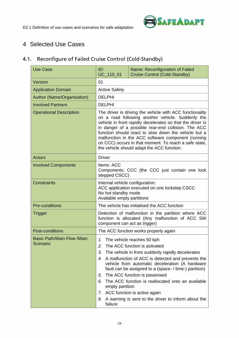
4.1. Reconfigure of Failed Cruise Control (Cold-Standby)
Use Case ID: UC_110_01
Name: Reconfiguration of Failed Cruise Control (Cold-Standby)
Version 01
Application Domain Active Safety
Author (Name/Organisation) DELPHI
Involved Partners DELPHI
Operational Description The driver is driving the vehicle with ACC functionality on a road following another vehicle. Suddenly the vehicle in front rapidly decelerates so that the driver is in danger of a possible rear-end collision. The ACC function should react to slow down the vehicle but a malfunction in the ACC software component (running on CCC) occurs in that moment. To reach a safe state, the vehicle should adapt the ACC function.
Actors Driver
Involved Components Items: ACC Components: CCC (the CCC just contain one lock stepped CSCC)
Constraints Internal vehicle configuration: ACC application executed on one lockstep CSCC No hot standby mode Available empty partitions
Pre-conditions The vehicle has initialised the ACC function
Trigger Detection of malfunction in the partition where ACC function is allocated (Any malfunction of ACC SW component can act as trigger)
Post-conditions The ACC function works properly again
Basic Path/Main Flow /Main Scenario
1. The vehicle reaches 50 kph
2. The ACC function is activated
3. The vehicle in front suddenly rapidly decelerates
4. A malfunction of ACC is detected and prevents the vehicle from automatic deceleration (A hardware fault can be assigned to a (space- / time-) partition)
5. The ACC function is passivised
6. The ACC function is reallocated onto an available empty partition
7. ACC function is active again
8. A warning is sent to the driver to inform about the failure

D2.1 Definition of use cases and scenarios for safe adaptation
25
Exception Paths/Alternate Flows /Alternate Scenario
No alternate paths
Expected Results The vehicle adapts its speed to follow the preceding car in a safe manner
High-level Design Requirements
Overall time response should be less than 50ms (fault detection: 10ms; passivation: 10ms) CSCC should register hardware partitions status
High-level Safety Adaptation Requirements
When HW partitions are available in the current CSCC duplex control computer, item functions (SW part) should be reconfigured using empty pre-configured partitions

D2.1 Definition of use cases and scenarios for safe adaptation
26
4.2. Steer-By-Wire Adaptation after ECU-Failure (CSCC-Failover)
Use Case ID: UC_111_01
Name: Steer-By-Wire Adaptation after ECU-Failure (CSCC-Failover)
Version 01
Application Domain Chassis
Author (Name/Organization) SIEMENS
Involved Partners SIEMENS
Operational Description The vehicle is driving on a main road. A short circuit leads to an immediate failure of a CSCC
Actors Driver
Involved Components Items: SBW, ACC, SomnoAlert Components: two CSCCs
Constraints Internal vehicle configuration: Two CSCCs (First: SBW master, ACC; Second: SBW hot-standby, SomnoAlert) Partial hot standby (only SBW) No unused partitions Ranking of applications based on priorities and interdependencies
Pre-conditions The vehicle has initialised all functions
Trigger An unintended short circuit leads to an immediate failure of a first CSCC hosting SBW master and ACC
Post-conditions SBW and ACC are fully functional before driver loses control of vehicle
Basic Path/Main Flow /Main Scenario
1. Vehicle reaches 50 km/h.
2. An unintended short circuit leads to an immediate failure of a first CSCC
3. SBW hot-standby is set into master mode on second CSCC
4. SomnoAlert is passivised on second CSCC
5. ACC is activated in partition previously occupied by SomnoAltert
6. A warning is sent to the driver to inform about the failure
Exception Paths/Alternate Flows /Alternate Scenario
No alternate paths
Expected Results SBW and ACC are fully functional before driver loses control of vehicle
High-level design requirements
Overall time response should be less than 50ms
High-level safety adaptation requirements
-

D2.1 Definition of use cases and scenarios for safe adaptation
27
4.3. Adaptation after Break-by-Wire Malfunction (Dependable Function)
Use Case ID: UC_114_01
Name: Adaptation after Break-by-Wire Malfunction (Dependable Function)
Version 01
Application Domain
Author (Name/Organisation) DELPHI
Involved Partners DELPHI, SIEMENS, FICOSA, TTECH
Operational Description The vehicle is driving on a road while the SomnoAlert function is monitoring the driver alertness. An obstacle appears on the road and the AEB (Automatic Emergency Brake) has to be activated to avoid a collision but the BBW (Brake-by-Wire) function does not react. Involved functions have different ASIL classification (A, C and D), therefore safe state must be reached by passivising a less critical function (SomnoAlert) should in order to maintain AEB and BBW functionality.
Actors Driver
Involved Components Items: ACC, AEB, RACAM, BBW, SomnoAlert Components: RACAM, 2 TTEthernet Switches, 2 CSCCs
Constraints Internal vehicle configuration: Two CSCC (lock stepped or duplex control-computer) No hot standby Ranking of applications based on priorities and interdependencies
Pre-conditions The vehicle has initialised BBW, ACC, AEB and SomnoAlert functions
Trigger Detection of malfunction on the BBW component (hardware failure can be assigned to an application) that can cause a delayed braking force response
Post-conditions The SomnoAlert function is passivised and the BBW and the AEB function work properly again
Basic Path/Main Flow /Main Scenario
Considering there are no available empty partitions:
1. The vehicle reaches 50 kph.
2. The SomnoAlert and ACC functions are activated
3. Obstacle is detected so that AEB function is automatically activated
4. A hardware fault affecting only BBW’s partition is detected. It can be assigned to a (space- / time-) partition
5. The AEB function is activated (no brake hardware diagnostic in AEB function)
6. The BBW function is passivised
7. Since there is not any empty partition, by taking

D2.1 Definition of use cases and scenarios for safe adaptation
28
into account functions priorities and dependencies, partition of SomnoAlert should be assigned to BBW
8. The SomnoAlert function is passivised and removed
9. The BBW function is reconfigured and activated
10. A warning is sent to the driver
Exception Paths/Alternate Flows /Alternate Scenario
Considering there are available empty partitions to activate one additional function.
1. The vehicle reaches 50 kph
2. The SomnoAlert and ACC functions are activated
3. Obstacle is detected so the AEB function is activated
4. A hardware fault affecting only BBW’s partition is detected. It can be assigned to a (space- / time-) partition
5. The AEB function is activated
6. The BBW function is passivised
7. The BBW function is reconfigured onto the empty partition and activated
8. A warning is sent to the driver
Expected Results The vehicle stops to avoid collision with the obstacle
High-level Design Requirements
Overall time response should be less than 50ms (fault detection: 10ms; passivation: 10ms). CSCC should register hardware partitions status CSCC should register applications with its priorities and interdependencies Minimising of applications passivation and reconfiguration should be accomplished
High-level Safety Adaptation Requirements
When no HW partitions are available in the vehicle configuration, item functions (SW part) with the less safety ASIL classification should be passivised Item functions that depend on the passivised ones should be also passivised When HW partitions are available in the current configuration, item functions (SW part) should be reconfigured using empty pre-configured partitions Item functions (SW part) should be reconfigured in the available partitions according to its priorities (D, C, B, A, QM).

D2.1 Definition of use cases and scenarios for safe adaptation
29
4.4. Communication Failure with External Aggregate (Hot-Standby)
Use Case ID: UC_116_01
Name: Communication Failure with External Aggregate (Hot-Standby)
Version 01
Application Domain
Author (Name/Organisation) TTTECH
Involved Partners DELPHI, SIEMENS, TTTECH
Operational Description The vehicle is driving with an ACC function on a road following another vehicle. Suddenly the vehicle in the front rapidly decelerates so that the driver is in danger of a possible rear-end collision. The ACC function should react to slow down the vehicle but a malfunction in sensor communication to the ACC is detected at this moment. The receiver will decide which path of the network is used.
Actors Driver
Involved Components Items: ACC Components: RACAM, 2 TTEthernet switches, 2 CSCCs
Constraints Internal vehicle configuration: Two CSCCs with ACC executed in master and hot-standby mode
Pre-conditions The vehicle has initialised all functions
Trigger A hard deceleration of the vehicle in front Detection of failure that can be assigned to communications between CSCC hosting master ACC and external aggregate
Post-conditions The hot-standby ACC will take over the communications with external aggregate (RACAM)
Basic Path/Main Flow /Main Scenario
1. The vehicle reaches 80 kph
2. The ACC function is activated
3. The vehicle in front decelerates rapidly
4. Internal malfunctioning behaviour: hardware fault can be assigned to communications with an external aggregate (RACAM) since message-failure are observed at least on one communication link but just in one duplex control-computer (where the master ACC application is running)
5. Master ACC application is passivised
6. Hot-standby ACC application takes over the communications with external aggregate (RACAM)
7. A warning is sent to the driver
Exception Paths/Alternate Flows /Alternate Scenario
No alternate paths

D2.1 Definition of use cases and scenarios for safe adaptation
30
Expected Results The vehicle adapts its speed to follow the preceding car in a safe manner
High-level design requirements
Overall time response should be less than 50ms (fault detection: 10ms; passivation: 10ms) CSCC should manage master/hot-standby mode of applications
High-level safety adaptation requirements
When having hot-standby configuration, item functions (SW part) can be reconfigured by performing a switch from a CSCC hosting a master instance to CSCC hosting a hot-standby instance.

D2.1 Definition of use cases and scenarios for safe adaptation
31
4.5. Installation of New Component (New)
Use Case ID: UC_211_01
Name: Installation of New Component (New)
Version 01
Application Domain -
Author (Name/Organisation) SIEMENS
Involved Partners DELPHI, SIEMENS
Operational Description The driver wants to upgrade the vehicle by installing a new component at an official maintenance service provider. Once in the garage, the maintenance service provider proceeds to perform all required overhaul operations.
Actors Maintenance service provider Driver / vehicle owner
Involved Components Vehicles: VSIEMENS Components: RACE, TMDP, New Component
Constraints ICT is running in maintenance mode
Pre-conditions Maintenance service provider has the appropriate devices to install the components in vehicles. The component to be installed is available for the vehicle owner.
Trigger During the dispatch mode, CCC detects a new component and triggers the adaption mechanism to certify the new hardware.
Post-conditions The additional component is installed. Configuration of safe adaptation core SAPC is initiated on all platforms (RACE, TMDP).
Basic Path/Main Flow /Main Scenario
1. Maintenance service provider connects the installer device to the central ICT computing core CCC
2. Maintenance service provider starts an application on the central ICT computing core CCC which has the clearance to integrate new components (user authentication will be required)
3. The component is installed 4. The approval of the component is verified 5. The safe adaptation core SAPC is properly
configured and initiated on all platforms (RACE, TMDP)
Exception Paths/Alternate Flows /Alternate Scenario
1. Maintenance service provider sets up a new hardware in the vehicle
2. Maintenance service provider connects the installer device to the central ICT computing core CCC
3. Maintenance service provider starts an application on the central ICT computing core CCC which has the clearance to implement new components (user authentication will be required)
4. The software belonging to the new hardware is

D2.1 Definition of use cases and scenarios for safe adaptation
32
selected (see UC_311_01) 5. The approval of the software is verified 6. The new software is installed on the central ICT
computing core CCC 7. The safe adaptation core SAPC is properly
configured and initiated on all platforms (RACE, TMDP)
Expected Results An additional aggregated component is installed. The safe adaptation core SAPC is initiated with the new configuration and it is running in normal operation.
High-level design requirements
Application on the central ICT computing core CCC which has the clearance to implement new software. Such application has to face common security requirements (authentication, integrity, …) to avoid installations of illegal or harmful software, or software that is installed by third parties to without the awareness of the owner.
High-level safety adaptation requirements
The safe adaptation core SAPC is properly configured and initiated on all platforms (RACE, TMDP) after installing new components
D2.1 Definition of use cases and scenarios for safe adaptation
33
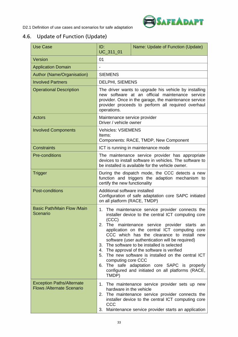
4.6. Update of Function (Update)
Use Case ID: UC_311_01
Name: Update of Function (Update)
Version 01
Application Domain -
Author (Name/Organisation) SIEMENS
Involved Partners DELPHI, SIEMENS
Operational Description The driver wants to upgrade his vehicle by installing new software at an official maintenance service provider. Once in the garage, the maintenance service provider proceeds to perform all required overhaul operations.
Actors Maintenance service provider Driver / vehicle owner
Involved Components Vehicles: VSIEMENS Items: Components: RACE, TMDP, New Component
Constraints ICT is running in maintenance mode
Pre-conditions The maintenance service provider has appropriate devices to install software in vehicles. The software to be installed is available for the vehicle owner.
Trigger During the dispatch mode, the CCC detects a new function and triggers the adaption mechanism to certify the new functionality
Post-conditions Additional software installed Configuration of safe adaptation core SAPC initiated on all platform (RACE, TMDP)
Basic Path/Main Flow /Main Scenario
1. The maintenance service provider connects the installer device to the central ICT computing core (CCC)
2. The maintenance service provider starts an application on the central ICT computing core CCC which has the clearance to install new software (user authentication will be required)
3. The software to be installed is selected 4. The approval of the software is verified 5. The new software is installed on the central ICT
computing core CCC 6. The safe adaptation core SAPC is properly
configured and initiated on all platforms (RACE, TMDP)
Exception Paths/Alternate Flows /Alternate Scenario
1. The maintenance service provider sets up new hardware in the vehicle
2. The maintenance service provider connects the installer device to the central ICT computing core CCC
3. Maintenance service provider starts an application
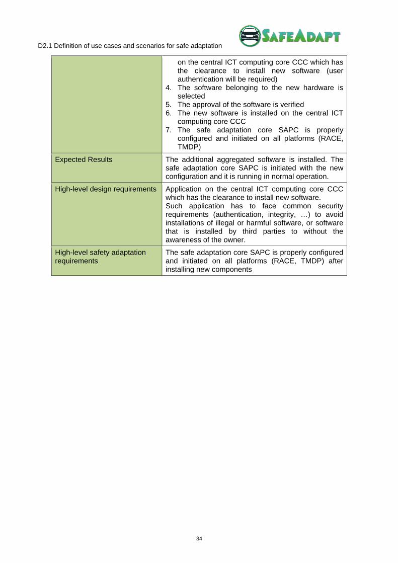
D2.1 Definition of use cases and scenarios for safe adaptation
34
on the central ICT computing core CCC which has the clearance to install new software (user authentication will be required)
4. The software belonging to the new hardware is selected
5. The approval of the software is verified 6. The new software is installed on the central ICT
computing core CCC 7. The safe adaptation core SAPC is properly
configured and initiated on all platforms (RACE, TMDP)
Expected Results The additional aggregated software is installed. The safe adaptation core SAPC is initiated with the new configuration and it is running in normal operation.
High-level design requirements Application on the central ICT computing core CCC which has the clearance to install new software. Such application has to face common security requirements (authentication, integrity, …) to avoid installations of illegal or harmful software, or software that is installed by third parties to without the awareness of the owner.
High-level safety adaptation requirements
The safe adaptation core SAPC is properly configured and initiated on all platforms (RACE, TMDP) after installing new components

D2.1 Definition of use cases and scenarios for safe adaptation
35
Possible involved functions: The below picture shows a steer-by-wire logic architecture. Three sensors measure the current position of the steering axle and a steering linkage controller can steer the car via sending commands to a motor and three redundant position sensors that is connected to the steering axle. The steer-by-wire application, as a part SW and runs on the CCC, contains one type of a steer-by-wire function or program that translates the steering commands given from three redundant sensors from the steering wheel. In this adaption scenario, the steer-by-wire functionality is replaced by a different steer-by-wire functionality (1) that is called dynamic steer-by-wire. This dynamic version requires, as the former steer-by-wire function, ASIL D steering wheel position data and the ability to steer the car also with ASIL D to work correctly, but additionally requires an ASIL B compliant vehicle speed information to let the car react softer on steering wheel movements during a higher driving speed. During the deployment phase, the new dynamic steer-by-wire function is deployed onto the CCC. After having done a safety assessment and other quality-checks, the CCC decides whether the car can be set with the new function into normal operation or not.
X
X
X
Ste
erin
g Li
nkag
e C
ontr
olle
r
MM
X
X
X
Ste
erin
g W
hee
l Se
nso
rs
Fun
ctio
nD
irect
Ste
er-b
y-W
ire
Fu
nct
ion
Dyn
am
ic S
tee
r-by
-Wire
CC
C
EC
U
Requires ASIL D steering
AS
IL D
AS
IL D
AS
IL D
AS
IL D
AS
IL B
AS
IL B
(D)
AS
IL B
(D)
AS
IL B
(D)
AS
IL B
(D)
AS
IL B
(D)
AS
IL B
(D)
1
2
Requires ASIL B vehicle speed
Requires ASIL D steering wheel position data

D2.1 Definition of use cases and scenarios for safe adaptation
36
4.7. Degradation of Steer-By-Wire Application (Internal)
Use Case ID: UC_411_01
Name: Degradation of Steer-By-Wire Application (Internal)
Version 01
Application Domain Chassis
Author (Name/Organisation)
Involved Partners SIEMENS, DELPHI
Operational Description The vehicle is driving on a road and the SBW application experiments a failure while operating in regular mode so that it is not able to function correctly. As a SBW basic application is available to work in a degraded mode, it has to be activated to reach a safe state.
Actors Driver
Involved Components Items: SBW Components: two CSCCs
Constraints There are two modes for the SBW application to operate: regular mode and degraded mode
Pre-conditions There are two implementations of the same application (SBW), one for regular mode operation and a second more basic one with degraded mode operation
Trigger The regular mode of the application suddenly fails
Post-conditions A reconfiguration is required. The SBW application only offers a basic functionality but continues working.
Basic Path/Main Flow /Main Scenario
1. The vehicle reaches 30 kph
2. The driver presses the brake pedal 3. The complete SBW application detects a failure
and the regular mode of operation is not able to continue operation
4. The failure is detected 5. The complete SBW application is passivised 6. CSCC only has resources to configure and
instantiate the basic SBW application instead of the complete SBW
7. A warning is sent to the driver in order to inform about the failure
Exception Paths/Alternate Flows /Alternate Scenario
1. The complete SBW application detects a failure and the regular mode of operation is not able to continue working
2. The failure is detected 3. The complete SBW application is passivised 4. CSCC has no resources to configure a new
application 5. The basic SBW application is configured in another
CSCC
D2.1 Definition of use cases and scenarios for safe adaptation
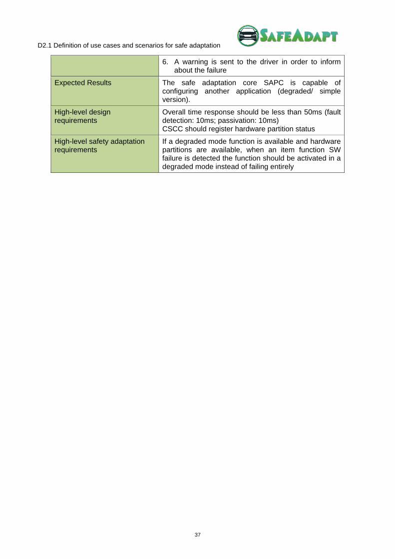
37
6. A warning is sent to the driver in order to inform about the failure
Expected Results The safe adaptation core SAPC is capable of configuring another application (degraded/ simple version).
High-level design requirements
Overall time response should be less than 50ms (fault detection: 10ms; passivation: 10ms) CSCC should register hardware partition status
High-level safety adaptation requirements
If a degraded mode function is available and hardware partitions are available, when an item function SW failure is detected the function should be activated in a degraded mode instead of failing entirely
D2.1 Definition of use cases and scenarios for safe adaptation
38
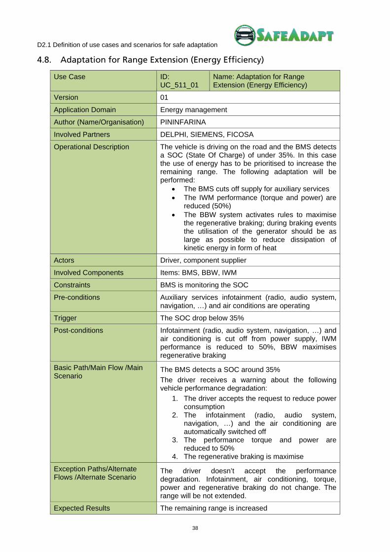
4.8. Adaptation for Range Extension (Energy Efficiency)
Use Case ID: UC_511_01
Name: Adaptation for Range Extension (Energy Efficiency)
Version 01
Application Domain Energy management
Author (Name/Organisation) PININFARINA
Involved Partners DELPHI, SIEMENS, FICOSA
Operational Description The vehicle is driving on the road and the BMS detects a SOC (State Of Charge) of under 35%. In this case the use of energy has to be prioritised to increase the remaining range. The following adaptation will be performed:
The BMS cuts off supply for auxiliary services The IWM performance (torque and power) are
reduced (50%) The BBW system activates rules to maximise
the regenerative braking; during braking events the utilisation of the generator should be as large as possible to reduce dissipation of kinetic energy in form of heat
Actors Driver, component supplier
Involved Components Items: BMS, BBW, IWM
Constraints BMS is monitoring the SOC
Pre-conditions Auxiliary services infotainment (radio, audio system, navigation, …) and air conditions are operating
Trigger The SOC drop below 35%
Post-conditions Infotainment (radio, audio system, navigation, …) and air conditioning is cut off from power supply, IWM performance is reduced to 50%, BBW maximises regenerative braking
Basic Path/Main Flow /Main Scenario
The BMS detects a SOC around 35%
The driver receives a warning about the following vehicle performance degradation:
1. The driver accepts the request to reduce power consumption
2. The infotainment (radio, audio system, navigation, …) and the air conditioning are automatically switched off
3. The performance torque and power are reduced to 50%
4. The regenerative braking is maximise
Exception Paths/Alternate Flows /Alternate Scenario
The driver doesn’t accept the performance degradation. Infotainment, air conditioning, torque, power and regenerative braking do not change. The range will be not extended.
Expected Results The remaining range is increased

D2.1 Definition of use cases and scenarios for safe adaptation
39
High-level design requirements
CSCC should register energy efficiency level for all applications
High-level safety adaptation requirements
Item functions (SW part) should be reconfigured in the available partitions according to their priorities (D, C, B, A, QM). If several Item functions (SW part) have the same ASIL, they should be reconfigured according to energy efficiency optimisation criteria.

D2.1 Definition of use cases and scenarios for safe adaptation
40
5 Configurations
Depending of the characteristics of the application it may be integrated onto a real vehicle platform or a virtual one. These platforms are generally considered to be two independent configurations:
Vehicle Configuration: Consists of applications and systems that will be integrated onto a real vehicle (in this case the SIEMENS’s vehicle). There might be more than one of these configurations if the applications or system needs to be tested separately.
Simulated Configuration: Consists of applications that are problematic to integrate into a real vehicle. These application may however still be simulated to avert the risk associated with integrating experimental functions into a real vehicle. There might be more than one of these configurations if applications or systems need to be tested separately.
5.1. VSIEMENS Configuration
The RACE car has been developed within the German national funded project RACE (Robust and reliable Automotive Computing Environment for future eCars, see www.projekt-race.de). The goal is to demonstrate the software- and system architecture developed in that project in a real working car, which could potentially be certified for usage on public roads. All functions, such as braking, driving or steering, can be realised by the RACE architecture using a centralised computing platform.
Figure 4: The RACE Demonstrator Car
The car is built using a small-series commercial car from Roding Automobile (see http://www.roding-automobile.de). It main characteristics are:
Fully electric drive train with wheel hub motors: The two wheel hub motors on the rear axle provide a continuous power of 63kw and a peak power of 115kw. The maximum torque is 1250 Nm and the continuous torque is 500 Nm. This power is mainly used to recuperate a high degree of the energy during breaking in order to enhance energy efficiency and fine dust emissions. That way, more than 70% of breaking incidents can be performed using only electric machines.
Electrical controlled braking system, which is fully controlled by the RACE platform. “Brake Blending” is a function which tries to distribute the require braking force between the

D2.1 Definition of use cases and scenarios for safe adaptation
41
braking system and the wheel hub motors. Only in cases when the braking power of the wheel hub motors is insufficient, the electronic braking system is used.
A full steer-by-wire system with redundant steering actors and sensors, implemented on top of the RACE E/E architecture. In contrast to commercially available products, e.g. from Nissan, the steer –by-wire system does not have a mechanical backup. High availability and hence safety is provided only by the redundant E/E system.
A multitude of sensors like lidar, ultrasound, and cameras which can be used to develop and to demonstrate new automotive functions such as advanced drivers assistance functions or functions for autonomous driving. These are mostly off-the-shelf sensors, which are connected to the RACE system via gateways.
The RACE demonstrator car provides a fully redundant E/E architecture. Safety critical systems, like the steer-by-wire system or the pedal box, are supplied by two different power circuits. Likewise, the communication architecture of the car is fully redundant, using an Ethernet ring structure. To reduce cabling, less critical components like parking sensor can be connected in a non-redundant way. The central computing platform consists of several Duplex Control Computers (DCCs) in order to provide a fail-operational system.
Figure 5: Redundant Power Supply, Computation & Communication of RACE Car

D2.1 Definition of use cases and scenarios for safe adaptation
42
5.2. DYNACAR Configuration
Dynacar configuration provides a virtual environment to simulate a vehicle with the possibility to validate and to verify different parts of a car. Dynacar configuration is based on DYNACAR RT product from TECNALIA.
5.2.1. DYNACAR Overview
DYNACAR RT solution is based on:
RT testing platform software (Veristand® real time framework) Graphic visualisation system and vehicle control for real test driving in a virtual environment Dynamic vehicle model running on RT equipment (PXI hardware) Test bench hardware depending on the user configuration (ECU, suspension rig,
dynamometer, battery test rig, …)
Figure 6: Schematic DYNACAR RT Solution with Software and Hardware Definition
Vehicles can be modelled, introducing vehicle design parameters with a dedicated GUI. All vehicle dynamics (rolling chassis in Figure 6) is coded in NI LabView, and can run in RT.
The modelling of basic vehicle dynamics is based on a rolling stiffness model, and the key characteristics of the model are the following:
• The vehicle dynamics are modelled with 3 solid bodies (roll stiffness model as shown is Figure 7), front and rear axle and vehicle body
• The suspension system is modelled with roll centre, roll stiffness and damping, with wheel angles dependant of the roll and steering angle
• Good compromise between result accuracy and data needed to model the vehicle, with low computational effort, and real-time capabilities
• The vertical loads on tires are obtained accurately, using Magic Formula 5.2 for modelling tire to road contact, with real time solving of tire forces (Fx, Fy, Fz)
• Straightforward implementation of “Hardware in the loop” based on the NI architecture

D2.1 Definition of use cases and scenarios for safe adaptation
43
• Basic vehicle and circuit library available, with vehicle dynamic model accuracy (longitudinal and lateral forces) validated versus real vehicle, with good matching results of less than 5% of deviation from real acquired data in real vehicle
Figure 7: Roll Stiffness Model and 3D Model of Test Vehicle (see http://www.youtube.com/watch?v=-D8BWobk3HE&feature=player_detailpage#t=313s)
Real time vehicle simulation platform based on Dynacar offers the following advantages:
• Fully-developed in Labview RT, therefore deterministic performance • Loop solving time less than 1 ms in RT (using PXI 8110) • Computational load distributed in PXI 8110 CPU cores for maximum efficiency • Integrated in RT test platform software (Veristand by National Instruments and INERTIATM
plugin by Wineman Technologies Inc.) • Available for HIL of ECUs, combining HIL input with defined tests (standard drive cycles,
physical tests…) • Deterministic, robust and fast prototyping solutions for HW integration
Graphic engine for “Human in the loop” testing and advanced visualisation has the following main characteristics (see Figure 8):
• Stereoscopic 3D virtual environment • Virtual proving ground (with cone editor) and test circuit are available • Multiple displays supporting for immersive experience in virtual environment • Human in the Loop capabilities, generating tests in real time • Easy installation (plug & play) • Additional information for visualisation (loads, wheel path, effects...) • Different “white brand” vehicle bodies with baseline setup
Figure 8: Graphic Engine with the Test Vehicle for Dynamic Model Validation on Real Circuit

D2.1 Definition of use cases and scenarios for safe adaptation
44
5.2.2. DYNACAR RT
DYNACAR RT is designed to allow running a real time simulation of an entire vehicle, with hardware in the loop and driver in the loop capabilities.
Figure 9: Example of DYNACAR RT Configuration
In Figure 9 the suggested hardware and software configuration is shown, with a NI PXI as a real time platform running the DYNACAR RT virtual vehicle model. The other two computers connected via Ethernet are recommended, one for the vehicle and scenario configuration and visual management (driving scenarios), and the second for the test configuration and logging (running INERTIA test automation software).
DYNACAR RT virtual vehicle model runs in the NI PXI platform in real time, and can be connected to different hardware devices (test bench, electric motor...). NI PXI is also connected with the visuals PC, in order to update the vehicle position in real time (less than 1ms), and with the test automation PC, to follow the designed test and log the test data.
The visualisation part of DYNACAR RT runs in the visuals PC, connected to a steering wheel and one or more screens depending on configuration.
The test automation and logger software INERTIA/VERISTAND is executed on a test automation PC.
5.2.3. System Requirements of DYNACAR
DYNACAR RT software is based on two different hardware platforms working together; the developing and virtual driving simulator framework (based on x86 platform), and the virtual vehicle model platform installed in a NI PXI RT platform. Both are connected via Ethernet as depicted in the following figure:
Dynacar RT software
Dynacar RT Visual software
Inertia/Veristand software

D2.1 Definition of use cases and scenarios for safe adaptation
45
Figure 10: DYNACAR RT Implementation Scheme
Developing and virtual driving simulator framework
Developing and virtual driving tools (driving simulator) run on x86 platform with Windows XP 32-64 bit or Windows 7 32-64 bit OS.
General configuration when considering computer hardware selection is the following:
• Virtual driving computer (optional) requirements (Visual PC in Figure 10): o CPU: Core i7 or similar is preferable if three screen configurations are going to be
used. In configurations with only one screen Core i5 or similar can be used. Memory requirements are 2 GB minimum for 32 bit and 4 GB minimum for 64 bit version.
o Graphic: Graphic card with minimum NVidia GEFORCE GTX chipset, SLI ready. Two identical graphic cards will with three monitor configurations is recommended for more immersive driving experience, but one monitor configuration can be used with only one graphic card. Microsoft DirectX 11 is required.
Figure 11: Immersive Configuration with Three Screens and Two Graphic Cards

D2.1 Definition of use cases and scenarios for safe adaptation
46
o Driver in the loop: Logitech G27 steering wheel is necessary in order to get full potential of DYNACAR RT driver in the loop possibilities, connected to this computer.
o Storage: The virtual driving programme requires up to 2 GB of free space on hard disk
• Developer computer requirements (HOST PC in Figure 10): o Storage: GUI (Graphic User Interface) to configure DYNACAR RT package requires
about 200 MB of disk storage, and VERSISTAND framework software must be also installed. The minimum total hard disk space will be 30GB for the OS and the complete software package.
RT platform
RT platform is based on NI PXI device (shown in Figure 12), running DYNACAR RT software, with the following minimum configuration:
• The minimum hardware configuration is NI PXI 8110 Core 2 Quad 2.26 GHz with Real Time Embedded software, installed in a PXI 1031 4-slot chassis.
• The PXI minimum configuration should be upgraded with different I/O communication cards (CAN, LIN, FlexRay, Digital, Analog…), depending of the final user requirements.
Figure 12: NI-PXI 8110 RT hardware
5.2.4. DYNACAR and SafeAdapt Use Cases
DYNACAR is one of the tools included in the Tool Chain that is being generated in “WP4 Design Methodology & Tools”. WP4 will provide a detailed specification of the tool chain for verification and validation in the SafeAdapt project.
At the moment, a preliminary description of the inputs and outputs of Dynacar have been defined and a integrate Dynacar in the SafeAdapt tool chain has been outlined:
The model inputs/outputs can be linked internally using Veristand (from National Instruments) in case of being provided by another model/controller installed on the same HW or can be linked using any kind of communication, CAN, Ethernet, …, Serial. All the outputs are stored internally on the real time controller (PXI) in TDMS format (proprietary format from National Instruments for logging data) and can be easily exported into Matlab, …, Excel. This helps during the testing stages while verifying the results.
As soon as the WP4 progresses, a more detailed description of the configuration of Dynacar for the specific selected use cases and scenarios will be produced.

D2.1 Definition of use cases and scenarios for safe adaptation
47
6 Conclusions
This document comprises the selected use cases and scenarios to be developed in SafeAdapt. They have been selected according to “safety relevant” criteria, that is, conducting a HARA for the most relevant items and components involved in the project.
At this moment, a set of high level design requirement and high level safety adaptation requirements have been outlined:
• Summary of High Level Design requirements:
o Overall response time should be less than 50ms (fault detection: 10ms; passivation: 10ms) for all safety-critical functions that influence the drive dynamics
o CSCC should register hardware partitions status
o CSCC should register applications with its priorities and interdependencies
o Minimisation of application passivation and reconfiguration should be accomplished
o CSCC should manage master/hot-standby mode of applications
o Application on the central ICT computing core CCC which has the clearance to install new software. Such application has to face common security requirements (authentication, integrity, …) to avoid installations of illegal or harmful software, or software that is installed by third parties to without the awareness of the owner
o CSCC should register energy efficiency level for all applications
• Summary of High Level Safety Adaptation requirements:
o When HW partitions are available in the current CSCC, item functions (SW part) should be reconfigured using empty pre-configured partitions
o When no HW partitions are available in the current CCC, item functions (SW part) with the lowest ASIL classification should be passivised
o Item functions that depend on the passivised ones should be also passivised
o When HW partitions are available in the current configuration, item functions (SW part) should be reconfigured using empty pre-configured partitions
o Item functions (SW part) should be reconfigured in the available partitions according to its priorities (D, C, B, A, QM)
o If several Item functions (SW part) have the same ASIL priority (D, C, B, A, QM), they should be reconfigured according to energy efficiency optimisation criteria
o When having hot-standby configuration, item functions (SW part) can be reconfigured by performing a switch from a CSCC hosting a master function to a CSCC hosting a hot-standby function
o The safe adaptation core SAPC is properly configured and initiated on all platforms after installing new components
o If a degraded mode function is available and hardware partitions are available, when an item function SW failure is detected the function should be activated in a degraded mode instead of failing entirely

D2.1 Definition of use cases and scenarios for safe adaptation
48
Both sets of requirements are inputs for “WP3 Safe Adaptation Runtime Core”, and will be refined, as soon as the design of the runtime control and the safety goals are finally performed. At the same time, the use cases are input for “WP4 Design Methodology & Tools”.
On the one hand, some of the use cases are specially oriented towards WP4 in order to serve as the basis for testing design, verification, and validation processes covered by the tool chain.
On the other hand, one of the tools included in the WP4 tool chain is Dynacar that should be modified to satisfy SafeAdapt requirements. Dynacar will be available as a possible virtual configuration to simulate uses cases in WP5. This can be done as a preliminary step for the use case that should be evolved and integrated into a real configuration (physical car), or as method for analysing specific issues that cannot be performed in a real environment.

D2.1 Definition of use cases and scenarios for safe adaptation
49
Bibliography
OMG. (2012). Retrieved June 8, 2012, from Website of the Object Management Group - Systems Modeling Language version 1.3: http://www.omgsysml.org/
Ward, P., & Mellor, S. (1985). Structured Development for Real-Time Systems. New Jersey: Prence Hall.
D2.1 Definition of use cases and scenarios for safe adaptation
50
List of Abbreviations
ACC Adaptive Cruise Control
AEB Autonomous Emergency Braking
ADAS Advanced Driver Assistance Systems
AGG Aggregate ICT Information and Communication Technology
API Application Programming Interface
ASIL Automotive Safety Integrity Level
BBW Brake by Wire
BMS Battery Management System
CAN Controller Area Network
CCC Central ICT Computing Core
COTS Commercial Off-The-Shelf
CPU Central Processing Unit
CSCC Central ICT Sub Computing Cores
ECU Electronic Control Unit
F/E Fully Electric
FEV Fully Electric Vehicle
GPS Global Positioning Systems
GSB General Safety Board
GUI Graphic User Interface
GW Gateway
ITS Intelligent Transportation Systems
HARA Hazard and Risk Analysis
IWM In-Wheel Motor
OBU On Board Unit
OEM Original Equipment Manufacturer
OS Operating System
RACAM Combined Radar and Camera Module
RE Runtime Environment
RTOS Real Time Operating Systems
SAPC Central Safe Adaptation Platform Core
SASPC Safe Adaptation Sub Platform Cores
SBW Steer by Wire

D2.1 Definition of use cases and scenarios for safe adaptation
51
SOC State Of Charge
TMDP Trusted Multi Domain Platform
UC Use Case