d1.4 novel q-plates - europa
TRANSCRIPT

1
Deliverable Report
Deliverable No: D1.4
Deliverable Title: High quality q-plates with new geometries,
tunability, radial-mode corrections Grant Agreement number: 255914 Project acronym: PHORBITECH Project title: A Toolbox for Photon Orbital Angular Momentum Technology Project website address: www.phorbitech.eu Name, title and organization of the scientific representative of deliverable’s lead beneficiary (task leader): ________________________________________________________
Prof. Lorenzo Marrucci
Università di Napoli Federico II (UNINA)
Naples, Italy Deliverable table Deliverable no. D1.4 Deliverable name High quality q-plates with new
geometries, tunability, radial-mode corrections
WP no. 1 Lead beneficiary no. 3 (ICFO) Nature P, R Dissemination level PU Delivery date from Annex I Month 18 Actual delivery date 31 March 2012
2
D1.4) Novel q-plates: High quality q-plates with new geometries, tunability, radial-mode corrections[Excerpt from GA-Annex I DoW]
Excerpt from Annex I: This task is aimed at designing and manufacturing novel kinds of q-plates. The q-plate is a device invented in Naples (UNAP) that introduces an interaction of polarization and OAM degrees of freedom. It may be used in particular for controlling an OAM variation with the input polarization of an optical beam, thus enabling an OAM beam generation from a Gaussian input. The basic concept of the q-plate is simply that of suitably patterned birefringent wave-plates where the coupling with the wavefront arises from the geometrical Pancharatnam-Berry phase occurring in the optical polarization manipulations. Patterned wave-plates for the visible or near IR domain can be conveniently developed using liquid crystals technology. To obtain OAM states, the pattern must have a singularity of charge q at its center, allowing for the generation of OAM states with index m = ±2q, where the sign is determined by the input circular polarization content. Only specific simple patterns having circular symmetry have been realized so far (corresponding to q=1), but technologies for realizing arbitrary patterns do exist. Another issue is the tunability of the q-plate, corresponding to the control of the wave-plate overall birefringence retardation at a given wavelength. This task is organized into two sub-tasks put in series, which will be carried out in close collaboration between UNAP (designing and manufacturing q-plates and q-plate-based optical systems and testing their performances in the classical regime) and UROM (testing the same devices in the quantum regime). Subtask T1.2.1 – Novel q-plate development and quality improvement. Different approaches to higher-quality and more flexible patterning (holographic, UV masking, micro-rubbing, laser writing) will be considered and tested. Mechanical and electrical tuning will also be developed (presently only thermal tuning has been demonstrated). The goal will be that of producing q-plates with arbitrary q values and controlled birefringent retardation. In addition, tailoring of the generated radial mode will be also pursued with the goal of obtaining propagation-stable superpositions of different OAM modes (the idea here is the same as that given for the holographic approach, see Task WP1.1). UROM will characterize the quality of the q-plates developed by UNAP in the quantum few-photon regime, by exploiting the experimental and theoretical tools developed for the reconstruction of quantum transformations, very sensitive to the mode purity. The goal will be to optimize the conversion efficiency, quality of the mode generated, the wavelength tuning in the quantum regime of the device. The results of this subtask will be assessed at milestone MS6 and provide a necessary input to task WP2.2.
The sub-task (T1.2.1) has started at the beginning of the project and ended regularly at month 18 (Milestone MS6).
As a first step, we have developed and successfully demonstrated the electric tuning technology of q-plates [1], which guarantees a rapid switching and convenient control of the q-plate retardation. The mechanical tuning was also briefly tested, but it proved to be not sufficiently reliable so it was discarded.
Moreover, with the collaboration of a group based in Hong Kong (prof. V. Chigrinov) and specialized in manufacturing photosensitive materials, we have set up and demonstrated a first photo-induced patterning method based on blue light illumination, allowing for a more flexible patterning and leading to higher optical quality of the q-plates compared to the previous rubbing-based method. In particular, the Hong Kong group provided different photosensitive materials to be tested and advice and training in the photo-alignment procedures, while Naples group conceived the work and performed the experiments. This work has allowed the first demonstration of tunable q-plates having arbitrary topological charge q [2].
An automatic setup for q-plate manufacturing was developed in Naples. This programmable setup allows manufacturing of q-plates with arbitrary q (both integer, semi-integer and fractional) or, in principle, any other polarization pattern with angular dependence only (see, e.g., Fig. 1a). The setup can operate with both blue and UV (a He-Cd laser from VM-TIM, purchased specifically for this purpose) light source for writing. With this setup we have tested different materials, either provided by the Hong Kong group or alternative commercial ones. We have achieved UV laser writing of the q-plates, with the purpose of having more

3
durable high-quality devices, which can be used with laser light having a wavelength in the whole visible and near-infrared spectrum.
With this step, the research on the purely azimuthal-patterned q-plate devices as introduced in the project has been concluded, providing high quality samples with OAM conversion efficiencies ranging from 100:1 to 1000:1 (comparable to common liquid crystal devices) and central defect sizes down to a minimum of 10 µm (Fig. 2), able to operate in the whole visible spectrum and with the possibility of electrical tuning and switching. The subsequent work was devoted to finding more general useful patterns, and in particular investigating the possibility of radial patterning and even of arbitrary 2D laser writing.
A first result along this line is the following one. The q-plate manufacturing setup was used to create a new type of device, an OAM-mode converter, that can convert the impinging OAM eigenstate of order l into an equal-weight superposition of l and -l OAM modes. This converter is essentially made as a q-plate of charge q divided into 2q equal sectors which are rotated by 90 degree with respect to each other (see Fig. 1b for an example). These LC mode converters have similar quality properties and are controlled by electric field just as standard q-plates.
(a) (b)
Fig. 1 (a) a q-plate with q = 1/2, (b) an OAM-mode converter for l=1. Top row: pattern simulations. Bottom row: photos of samples placed between crossed polarizers under oblique illumination. The black fringes indicate the zones where the LC is oriented parallel to one of the polarizers and the bright zones correspond to other LC orientations. In case of the OAM-converter a disclination line in LC orientation is clearly visible under oblique illumination.
With the aim of introducing a more general patterning technology of the q-plates, another setup was developed based on a holographic approach. Essentially, this setup is based on a polarizing Mach-Zehnder interferometer that gives rise to an interference pattern between two orthogonally polarized beams. In the case of circular polarizations, no interference fringes are visible, but a linear polarization pattern is formed, depending on the wavefronts shape of two interfering beams, which can then be used to align the polymer coating of the q-plate cells so as to obtain a similar pattern of the optical axis. Such form of polarization-

4
holography technique allows single-step recording of different pattern structures, with both radial and azimuthal dependence. We demonstrated the capability of this setup to achieve radial patterning, by developing a liquid crystal lens (Fig. 3) based on the Pancharatnam-Berry phase, i.e. the same working principle as the q-plates (optical elements working on this principle are called Pancharatnam-Berry phase Optical Elements, or PBOEs).
Fig. 2 - An image of a q-plate with q =1, with a central defect having a radius smaller than 10 µm.
A set of these newly produced q-plates has been made available to UROM, which has tested their performances in the quantum regime and is using them for developing novel devices for OAM control of single photons and photon pairs. Some of the results have been reported as deliverables D2.2 (deterministic transferrers) and others are still under way and will be reported in future deliverables.
In a separate work, the q-plate capability of generating vector vortex beams was studied in UNAP [3]. A q = 0.5 q-plate was used to generate azimuthally and radially polarized beams with the possibility of high-speed switching between polarization patterns by changing the impinging polarization state. More complex polarization patterns of vector beams are achievable with different topological charges of the q-plates and are currenyl beying studied.
In addition to the main line of research based on liquid crystals, we have investigated samples of silver-doped glasses under laser exposure, demonstrating that a permanent q-plate-like structure may develop spontaneously in these systems [4]. The exposure time allows control of the birefringent retardation, so that this self-patterning approach might provide an alternative approach to q-plate manufacturing in the future.
Finally, in order to assess the present status of the possible q-plate applications, a survey of the recent literature on this topic was completed and published in a review article [5], which has been also selected by the journal as one of its highlights for 2011.
Fig. 3 (a) A pattern of a PBOE lens. (b) and (c) Lens photo under polarizing microscope, central zone and side zone respectively.

5
Publications included in this deliverable: [1] “Photon spin-to-orbital angular momentum conversion via an electrically tunable q-plate”, B. Piccirillo, V. D'Ambrosio, S. Slussarenko, L. Marrucci, E. Santamato, Appl. Phys. Lett. 97, 241104 (2010). [NOTE: this publication has also been reported as part of deliverable D2.2] [2] S. Slussarenko, A. Murauski, T. Du, V. Chigrinov, L. Marrucci, E. Santamato, “Tunable liquid crystal q-plates with arbitrary topological charge”, Opt. Express 19, 4085-4090 (2011). [3] J. M. Amjad, H. R. Khalesifard, S. Slussarenko, E. Karimi, L. Marrucci, E. Santamato, “Laser-induced radial birefringence and spin-to-orbital optical angular momentum conversion in silver-doped glasses”, Appl. Phys. Lett. 99, 011113 (2011). [4] F. Cardano, E. Karimi, S. Slussarenko, L. Marrucci, C. de Lisio, E. Santamato, “Polarization pattern of vector vortex beams generated by q-plates with different topological charges”, Appl. Opt. 51 (10), pp. C1–C6 (2012) [5] L. Marrucci, E. Karimi, S. Slussarenko, B. Piccirillo, E. Santamato, E. Nagali, F. Sciarrino, “Spin-to-orbital conversion of the angular momentum of light and its classical and quantum applications”, J. Opt. 13, 064001 (2011).

Photon spin-to-orbital angular momentum conversion via an electricallytunable q-plate
Bruno Piccirillo,1,a! Vincenzo D’Ambrosio,1 Sergei Slussarenko,1 Lorenzo Marrucci,1,2 andEnrico Santamato11Dipartimento di Scienze Fisiche, Università di Napoli “Federico II”, Complesso Universitario di Monte S.Angelo, 80126 Napoli, Italy2CNR-SPIN, Complesso Universitario di Monte S. Angelo, 80126 Napoli, Italy
!Received 20 October 2010; accepted 23 November 2010; published online 16 December 2010"
Exploiting electro-optic effects in liquid crystals, we achieved real-time control of the retardation ofliquid-crystal-based q-plates through an externally applied voltage. Electro-optic q-plates can beoperated as electrically driven converters of photon spin into orbital angular momentum, enablinga variation of the orbital angular momentum probabilities of the output photons over a time scale ofmilliseconds. © 2010 American Institute of Physics. #doi:10.1063/1.3527083$
For years the orbital angular momentum !OAM" of pho-tons has been consigned to a back seat in the study of bothclassical and quantum optics. This was partly due to the con-ceptual reason that, in general, the spin and orbital contribu-tions of the electromagnetic angular momentum cannot beconsidered separately,1 except within the paraxial approxi-mation. However, even in the small-angle limit, the OAM,due to the dearth of tools suitable for its manipulation, hasbeen used much less than spin angular momentum !SAM".No doubt, the interest for both fundamental and applicativeaspects of OAM has kept up with the development of meth-ods and devices for its manipulation. At present, the impor-tance of OAM for quantum optics is mainly due to the factthat it is defined on an infinite-dimensional Hilbert spaceand, by its own nature, could be suitable for implementingsingle-photon qudits, which may lead, for example, to sim-plifying quantum computations2 and improving quantumcryptography.3 The most commonly used methods for gener-ating and manipulating the OAM are based on computer gen-erated holograms !CGHs". A recently introduced tool forOAM control is a liquid-crystal-based birefringent plate withretardation ! and optical axis unevenly oriented according toa distribution with topological charge q, after which thename q-plate !QP".4 A QP modifies the angular momentumstate of an incident photon by giving to each of its circularlypolarized components a finite probability, depending on theretardation !, of finding the photon in a polarization statewith opposite helicity and OAM quantum number l increasedor decreased by the amount "l=2q, whether the initial helic-ity is positive or negative, respectively. In q-plates with q=1, the optical axis distribution is cylindrically symmetricaround the central defect and the total angular momentum ofthe incident photons is therefore conserved #SAM-to-OAMconversion !STOC"$. The adoption of such device in quan-tum optics has recently enabled the observation of two-photon Hong–Ou–Mandel coalescence interference of pho-tons carrying nonzero OAM and the demonstration of the 1→2 universal optimal quantum cloning of OAM-encodedqubits and qudits.5 Besides the topological charge q, a key-feature of a QP is the birefringent retardation since it enablesto regulate the probability of switching between l and l#2q,
i.e., the STOC efficiency, according to the wavelength of theinput photons. High efficiencies for generation, manipula-tion, and detection of OAM states are often desirable, espe-cially when only few photons are available.
In this paper, to achieve a full control of the STOC effi-ciency, we present an electro-optical q-plate !EOQP" whoseretardation may be changed through an externally appliedvoltage. Hitherto, STOC efficiencies exceeding 95% !signifi-cantly higher than the efficiencies of the CGHs" were ob-tained tuning the q-plate retardation ! by controlling the ma-terial temperature.6 A thermally tuned QP has been used witha Dove prism inserted into a Sagnac polarizing interferom-eter in order to generate arbitrary linear combinations ofOAM eigenstates with l= #2 by manipulating the polariza-tion state of an input linearly polarized TEM00 laser beam.7
The thermal tunability of ! arises from the temperature de-pendence of the liquid crystal order parameter and ultimatelyof the intrinsic birefringence of such material. The thermalcontrol of a QP assures an easy-to-made stable retardation atthe cost of a very slow time response. This is a limitationwhenever the experiment requires a real-time variation ofSTOC efficiency, for instance, for qudit manipulation orwhen more wavelengths are involved. Electric-field-basedregulation of ! enables one to overcome the time-responselimitations imposed by the thermal method and make QPssuitable for more demanding tasks. The working principle ofEOQP is based on the well-known property of external staticelectric or magnetic fields to change the orientation of theliquid-crystal molecular director n, representing the local av-erage orientation of liquid crystal molecules.8 We fabricatedand tested two EOQPs with q=1 so that the OAM impressedto converted photons is l= #2. These devices have differentthicknesses and have been manufactured by different meth-ods. The first was a nominal 20 $m thick film of E7 liquidcrystal from Merck Ltd., sandwiched between two indium-tin-oxide !ITO"-coated glass substrates, beforehand coatedwith a polyimide for planar alignment and circularly rubbed,as described elsewhere.6 The second EOQP was a nominal6 $m thick film of E7, sandwiched between two ITO-coatedglass substrates, beforehand coated with a polyimide UV-photoaligned for planar topologically charged optical axisdistribution. The ITO transparent conductive films work aselectrodes for the application of an electric field to the liquida"Electronic mail: [email protected].
APPLIED PHYSICS LETTERS 97, 241104 !2010"
0003-6951/2010/97"24!/241104/3/$30.00 © 2010 American Institute of Physics97, 241104-1

crystal. From now on, the former device will be referred toas EOQP1 and the latter as EOQP2. Adopting essentially thesame apparatus as that described in Ref. 6 for both the EO-QPs, we measured, as a function of the applied voltage, thepowers of the converted !Pc" and unconverted !Pu" compo-nents of the output beam for an incident !=532 nm circu-larly polarized TEM00 laser beam. The temperature of boththe EOQPs was maintained stable at 30 °C during measure-ments. Pu and Pc are expected to depend on the optical re-tardation " according to the Malus-like laws,6 Pu= P0 cos2!" /2" and Pc= P0 sin2!" /2", where P0 is the totaloutput power. In Fig. 1, the contrast ratios #!v"= !Pu− Pc" / !Pu+ Pc"=cos "!v" are shown for the rubbing-alignedand UV-photoaligned EOQPs, respectively, as functions ofthe rms values v of the applied 1 kHz ac voltage.9 The de-pendence of "!v" on the voltage arises from the torque ex-erted on the liquid crystal molecules by the applied electricfield.8 The behavior of "!v" vs v, as deduced from #!v", isshown in Fig. 2 for both devices. For v$vth=1.85%0.01 V, the nematic is undistorted in both the EO-QPs and "!0"="0=2&'nL /!+"0
!, where L stands for the
thickness of the cell, 'n=0.23 is the intrinsic birefringenceof the nematic E7 at 30 °C, and "0
! is a small constant re-sidual birefringence. For EOQP1, "0#1.7& and for EOQP2,"0#0.8&. For v=vth there is a discontinuity in the sloped" /dv. This is peculiar of a second order phase transitionbetween the unperturbed and the distorted conformations atthe critical voltage vth !Freédericksz transition".8 The theoryof electro-optical effects in liquid crystals8 predicts that vth=&$k11 /(0(a, where k11=9.2)10−12 N !30 °C" is the splayelastic constant of the liquid crystal,10 (0 is the vacuum di-electric constant, and (a=14.3 at 1 kHz at 30 °C.11 Actually,such expression returns vth*1 V, i.e., half the experimentalvalue. Such disagreement could be ascribed to the underlyingsimplified assumption of pure splay deformation. However,consistent with the theory, the experimental values of vth,within the experimental uncertainties, turn out to be the samefor both EOQPs, which differ from one another in the thick-ness only. In the limit of high applied voltage, the overallchange '="0−"!+"="0−"0
!=2&'nL /! is '#56.8 forEOQP1 and '#6.1 for EOQP2, yielding L#21 ,m forEOQP1 and L#2.3 ,m for EOQP2, respectively.
The different thicknesses of the cells are responsible forthe different saturation values of "!v" and for their differentswitching-off times. Assuming, for simplicity, that the initialdirector alignment is homogeneous, the switching-off reori-entation in the small distortion limit is expected to decayexponentially in time with a constant -=.1 /k11!L /&"2,where .1=150 mPa !30 °C" is the rotational viscosity of theliquid crystal.12 The time behavior of the switching-off Pcsignals is consistent with such prediction and the measureddecay time constants are -1=0.931%0.002 s and -2= !0.80%0.01")10−2 s, respectively !Fig. 3". These valuesare in reasonable agreement with those expected from theory,i.e., -1
theor=0.53 s and -2theor=0.62)10−2 s. Nevertheless,
consistent with the theoretical prediction for -, EOQP2, dueto its reduced thickness, switches off much faster than
!1.0
!0.5
0.0
0.5
1.0
Ρ
2 4 6 8 10 12 14!1.0
!0.5
0.0
0.5
1.0
Υ !V"
Ρ
(b)
(a)
FIG. 1. Measured contrast ratio #!v"=cos "!v" reported as function of v forEOQP1 !a" and EOQP2 !b". The continuous lines represent the theoreticalbehaviors.
v1,2th
0 2 4 6 8 10 12 140
10
20
30
40
50
60
Υ !V"
∆ 0!∆!rad"
FIG. 2. The optical phase change "!v" vs the applied voltage as extractedfrom the contrast #!v" for EOQP1 !"" and EOQP2 !#". The continuous linescorrespond to sixth order polynomial curve obtained by fitting the experi-mental data.
0.00
0.20
0.40
0.60
0.80
1.00
Pc#P 0
% 102
0 5 10 15 20 25 300.80
0.85
0.90
0.95
1.00
t !ms"
Pc#P 0
(a)
(b)
FIG. 3. Time decay of the power of the converted components of the outputbeam for EOQP1 !a" and EOQP2 !b" after the voltage switch-off. The start-ing voltages were v1=2.8 V for EOQP1 and v2=2.2 V for EOQP2 so thatthe dynamics may be approached in the small distortion limit and comparedwith theory !continuous lines". The time scale in panel !a" is slower by afactor of 100 with respect to panel !b".
241104-2 Piccirillo et al. Appl. Phys. Lett. 97, 241104 !2010"

EOQP1 and may be used for fast switching between differentvalues of !, as shown in Fig. 4. Finally, in order to check thatthe EOQPs actually work as SAM-to-OAM converters, theOAM of the output beam was directly measured adopting amethod of sorting between l=0 and l= "2 based on a polar-izing Sagnac interferometer, with a Dove prism insertedalong one of its arm, as elsewhere suggested.7 For EOQP1,the contrast ratio between the OAM components of the out-put beam was measured as #!v"= !P0− P2" / !P0+ P2", whereP0 and P2 are the powers of the l=0 and l= #2# output com-ponents, respectively. In Fig. 5, #!v" was reported, for com-parison, together with #!v", as reported in Fig. 1!a", but overa restricted voltage interval !5–10 V". The correlation be-tween the two signals is 99.6%.
In summary we realized an electro-optical SAM-to-OAM converter aimed not only at improving the handinessof classical QPs but also at performing unusual tasks exploit-ing the capability of EOQPs of managing superpositions ofOAM eigenstates with l=0, l=2, and l=−2 in real-time forhigh-dimensional qudits’ manipulation.
We acknowledge the financial support of the FET-OpenProgram within the Seventh Framework Programme ofthe European Commission under Grant No. 255914—Phorbitech.
1J. D. Jackson, Classical Electrodynamics !Wiley, New York, 1989".2A. Muthukrishnan and C. R. Stroud, Jr., Phys. Rev. A 62, 052309 !2000";B. P. Lanyon, M. Barbieri, M. P. Almeida, T. Jennewein, T. C. Ralph, K.J. Resch, G. J. Pryde, J. L. O’Brien, A. Gilchrist, and A. G. White, Nat.Phys. 5, 134 !2009".
3I. Bregman, D. Aharonov, M. Ben-Or, and H. S. Eisenberg, Phys. Rev. A77, 050301 !2008".
4L. Marrucci, C. Manzo, and D. Paparo, Phys. Rev. Lett. 96, 163905!2006".
5E. Nagali, F. Sciarrino, F. D. Martini, L. Marrucci, B. Piccirillo, E. Karimi,and E. Santamato, Phys. Rev. Lett. 103, 013601 !2009"; E. Nagali, L.Sansoni, F. Sciarrino, F. D. Martini, L. Marrucci, B. Piccirillo, E. Karimi,and E. Santamato, Nat. Photonics 3, 720 !2009"; E. Nagali, D. Giovan-nini, L. Marrucci, E. Santamato, and F. Sciarrino, Phys. Rev. Lett. 105,073602 !2010".
6E. Karimi, B. Piccirillo, E. Nagali, L. Marrucci, and E. Santamato, Appl.Phys. Lett. 94, 231124 !2009".
7E. Karimi, S. Slussarenko, B. Piccirillo, L. Marrucci, and E. Santamato,Phys. Rev. A 81, 053813 !2010".
8P. G. de Gennes, The Physics of Liquid Crystals !Oxford University Press,Oxford, 1974"; L. M. Blinov and V. G. Chigrinov, Electrooptic Effects inLiquid Crystal Materials !Springer, Berlin, 1996".
9An ac rather than a dc voltage is applied to avoid electrochemical degra-dation !Ref. 8".
10H. Hakemi, Mol. Cryst. Liq. Cryst. 287, 215 !1996".11H.-H. Liu and W. Lee, Appl. Phys. Lett. 97, 023510 !2010".12Z. Ran, P. Zeng-Hui, L. Yong-Gang, Z. Zhi-Gang, and X. Li, Chin. Phys.
B 18, 4380 !2009".
0.00 0.05 0.10 0.15!1.0
!0.5
0.0
0.5
1.0
t !s"
Ρ
FIG. 4. Time behavior of contrast ratio # for on-off switching of the appliedvoltage !von=3.2 V" for EOQP2.
6 7 8 9 10
!0.5
0.0
0.5
Υ !V"
Ρ,Ρ$
FIG. 5. Contrast ratio vs voltage for the output beam sorted with respect topolarization, #!v", !!" and with respect to OAM, #!v", !!". Data refer toEOQP1.
241104-3 Piccirillo et al. Appl. Phys. Lett. 97, 241104 !2010"

Tunable liquid crystal q-plates witharbitrary topological charge
Sergei Slussarenko,1,∗ Anatoli Murauski,2 Tao Du,2Vladimir Chigrinov,2 Lorenzo Marrucci,1,3 and Enrico Santamato1
1Dipartimento di Scienze Fisiche, Universita di Napoli “Federico II”, ComplessoUniversitario di Monte S. Angelo, 80126 Napoli, Italy
2Hong Kong University of Science and Technology, Clear Water Bay, Kowloon, Hong Kong3CNR-SPIN, Complesso Universitario di Monte S. Angelo, I-80126 Napoli, Italy
Abstract: Using a photoalignment technique with a sulphonic azo-dyeas the surfactant aligning material, we fabricated electrically tunable liquidcrystal q-plates with topological charge 0.5, 1.5 and 3 for generating opticalvortex beams with definite orbital angular momentum (OAM) 1,3 and 6per photon (in units of h), respectively. We carried out several tests onour q-plates, including OAM tomography, finding excellent performances.These devices can have useful applications in general and quantum optics.
© 2011 Optical Society of America
OCIS codes: (160.3710) Liquid crystals; (050.4865) Optical vortices.
References and links1. L. Allen, M. W. Beijersbergen, R. J. C. Spreeuw, and J. P. Woerdman, “Orbital angular momentum of light andthe transformation of Laguerre-Gaussian laser modes,” Phys. Rev. A 45, 8185–8189 (1992).
2. S. Franke-Arnold, L. Allen, and M. J. Padgett, “Advances in optical angular momentum,” Laser Photon. Rev. 2,299–313 (2008).
3. A. Jesacher, S. Furhapter, S. Bernet, and M. Ritsch-Marte, “Shadow effects in spiral phase contrast microscopy,”Phys. Rev. Lett. 94, 233902 (2005).
4. G. Gibson, J. Courtial, M. J. Padgett, M. Vasnetsov, V. Pasko, S. M. Barnett, and S. Franke-Arnold, “Free-spaceinformation transfer using light beams carrying orbital angular momentum,” Opt. Express 12, 5448–5456 (2004).
5. A. Mair, A. Vaziri, G. Welhs, and A. Zeilinger, “Entanglement of the angular momentum states of photons,”Nature 412, 313–315 (2001).
6. J. T. Barreiro, N. K. Langford, N. A. Peters, and P. G. Kwiat, “Generation of hyperentangled photon pairs,” Phys.Rev. Lett. 95, 260501 (2005).
7. G. Molina-Terriza, J. P. Torres, and L. Torner, “Twisted photons,” Nat. Phys. 3, 305–310 (2007).8. L. Aolita and S. P. Walborn, “Quantum communication without alignment using multiple-qubit single-photonstates,” Phys. Rev. Lett. 98, 100501 (2007).
9. M. W. Beijersbergen, R. P. C. Coerwinkel, M. Kristensen, and J. P. Woerdman, “Helical-wavefront laser beamsproduced with a spiral phaseplate,” Opt. Commun. 112, 321–327 (1994).
10. M. W. Beijersbergen, L. Allen, H. van der Veen, and J. P. Woerdman, “Astigmatic laser mode converters andtransfer of orbital angular momentum,” Opt. Commun. 96, 123–132 (1993).
11. V. Y. Bazheov, M. S. Soskin, and M. V. Vasnetsov, “Screw dislocations in light wavefronts,” J. Mod. Opt. 39,985–990 (1992).
12. Y. Igasaki, F. Li, N. Yoshida, H. Toyoda, T. Inoue, N. Mukohzaka, Y. Kobayashi, and T. Hara, “High efficiencyelectrically-addressable phase-only spatial light modulator,” Opt. Rev. 6, 339–344 (1999).
13. L. Marrucci, C. Manzo, and D. Paparo, “Optical spin-to-orbital angular momentum conversion in inhomogeneousanisotropic media,” Phys. Rev. Lett. 96, 163905 (2006).
14. L. Marrucci, C. Manzo, and D. Paparo, “Pancharatnam-Berry phase optical elements for wavefront shaping inthe visible domain: switchable helical modes generation,” Appl. Phys. Lett. 88, 221102 (2006).
15. E. Karimi, B. Piccirillo, E. Nagali, L. Marrucci, and E. Santamato, “Efficient generation and sorting of orbitalangular momentum eigenmodes of light by thermally tuned q-plates,” Appl. Phys. Lett. 94, 231124 (2009).
#136999 - $15.00 USD Received 22 Oct 2010; revised 10 Dec 2010; accepted 13 Dec 2010; published 16 Feb 2011(C) 2011 OSA 28 February 2011 / Vol. 19, No. 5 / OPTICS EXPRESS 4085

16. B. Piccirillo, V. DAmbrosio, S. Slussarenko, L. Marrucci, and E. Santamato, “Photon spin-to-orbital angularmomentum conversion via an electrically tunable q-plate,” Appl. Phys. Lett. arXiv:1010.4473 (in press).
17. E. Karimi, S. Slussarenko, B. Piccirillo, L. Marrucci, and E. Santamato, “Polarization-controlled evolution oflight transverse modes and associated pancharatnam geometric phase in orbital angular momentum,” Phys.Rev. A 81, 053813 (2010).
18. E. Nagali, L. Sansoni, F. Sciarrino, F. De Martini, L. Marrucci, B. Piccirillo, E. Karimi, and E. Santamato,“Optimal quantum cloning of orbital angular momentum photon qubits through hong-ou-mandel coalescence,”Nat. Photon. 3, 720–723 (2009).
19. S. Nersisyan, N. Tabiryan, D. M. Steeves, and B. R. Kimball, “Fabrication of liquid crystal polymer axial wave-plates for uv-ir wavelengths,” Opt. Express 17, 11926–11934 (2009).
20. P. G. de Gennes, The Physics of Liquid Crystals (Oxford University Press, Oxford, 1974).21. The strong anchoring at both the sample walls prevents the decay of the otherwise unstable disclination lines
with integer q.22. V. G. Chigrinov, V. M. Kozenkov, and H.-S. Kwok, Photoalignment of Liquid Crystalline Materials: Physics and
Applications (Wiley Publishing, 2008).23. D. F. V. James, P. G. Kwiat, W. J. Munro, and A. G. White, “Measurement of qubits,” Phys. Rev. A 64, 052312
(2001).24. The fidelity of the measured state |ψ〉 with respect to the expected state |ψ0〉 is usually defined as 〈ψ|ψ0〉2.25. B. Jack, J. Leach, H. Ritsch, S. M. Barnett, M. J. Padgett, and S. Franke-Arnold, “Precise quantum tomography
of photon pairs with entangled orbital angular momentum,” N. J. Phys. 11, 103024 (2009).26. E. Nagali, F. Sciarrino, F. De Martini, L. Marrucci, B. Piccirillo, E. Karimi, and E. Santamato, “Quantum infor-
mation transfer from spin to orbital angular momentum of photons,” Phys. Rev. Lett. 103, 013601 (2009).
1. Introduction
A light beam has two “rotational” degrees of freedom: spin angular momentum (SAM) andorbital angular momentum (OAM). The first is associated to the polarization of the transverseelectric field and may take the values s = ±h per photon, that correspond to circular left andright polarization, respectively. OAM is associated to the phase structure of the complex electricfield and paraxial beams with a helical phase front defined by the factor of exp(i!ϕ) carry adefinite amount of OAM per photon equal to !h, where ! can take any integer value [1, 2].In last years, beams carrying OAM have received an increased attention in classical [3, 4] andquantum optics [5–8]. Till now, fewmethods of OAM-carrying beam generation were proposed,namely spiral phase plates [9], astigmatic lens converters [1, 10] and computer generated forkholograms (CGH) [11] in conjunction with spatial light modulators (SLMs) [5, 12]. All thesemethods have in terms of efficiency, working speed and stability or have specific requirementsfor the input light state.Recently, a novel device based on liquid crystal (LC) technology, able to generate and ma-
nipulate the OAM was introduced [13, 14]. This device, called “q-plate” (QP) is essentially abirefringent wave plate with inhomogeneous patterned distribution of the local optical axis inthe transverse plane. The pattern of the optical axis distribution is defined by a semi-integertopological charge “q”. When a circularly polarized light beam traverses the QP, a±2q amountof OAM (in units of h) is transferred into the beam, with the sign determined by the input po-larization helicity. The efficiency of this conversion is given by the optical retardation δ of theQP, that can be controlled by temperature [15] or electrical field, as made in this work [16]. QPscan be very efficient, fast and stable, although they are less flexible than SLMs as they addressonly a OAM two-dimensional subspace.Till now, only q = 1 QPs were realized with LCs. Such device has already found a num-
ber of applications in various fields of optics [17, 18]. Polymer based QPs were manufacturedelsewhere [19], but such QPs, being solid and non-tunable, are suitable for single wavelength,require accurate control of thickness during manufacturing and cannot be used in applicationswhere the conversion efficiency must be changed or switched. In this paper we report the re-alization of LC-based δ -tunable QPs with arbitrary topological charge by a photoalignmenttechnology and demonstrate examples of QPs with q= 0.5,1.5 and 3.
#136999 - $15.00 USD Received 22 Oct 2010; revised 10 Dec 2010; accepted 13 Dec 2010; published 16 Feb 2011(C) 2011 OSA 28 February 2011 / Vol. 19, No. 5 / OPTICS EXPRESS 4086

2. Q-plate structure and fabrication
In the QP, the LC film is enclosed between glass walls perpendicular to the z-axis. Theorientation of the local optical axis of the QP is given by the LC molecular director distributionnnn(rrr) = (sinθ cosα,sinθ sinα,cosθ), with θ = θ(rrr),α = α(rrr) being the polar angles. Thewalls of the QPs are coated for parallel strong anchoring (θ = π/2) and the the surfacealignment profile is made so to have α(x,y) = α(ϕ) = qϕ + α0 in the LC bulk, whereϕ = arctan(y/x) is the transverse azimuthal coordinate, α0 is a real number, and q is an integeror half integer number. The surface texture induced by this distribution is known in the physicsof LC as a Schlieren structure with an isolated point defect (or “noyau”) of topological chargeq at the wall center [20]. The “noyaux” in the two walls of the cell are carefully alignedalong the z axis during the cell manufacturing, so that a disclination line of same charge q isgenerated in the bulk (from here the name q-plate of the device). As it is well known fromthe elastic theory of LC, the equivalence between nnn and −nnn implies that the charge q is eitherinteger or half-integer [21].
Fig. 1. (Color online) QP fabrication setup scheme.
The traditional way to manufacture a cell with planar alignment of liquid crystal is to rubthe inner sides of the glass walls, previously coated with thin layer of polyimide, with velvetfabric. The rubbing direction defines the anisotropy of the surface that, in turn, orient the LCmolecules perpendicular (or parallel, depending on the LC type) to the rubbing direction. Theq = 1 QPs can be manufactured in this way, by rubbing the cell walls with a rotating piece offabric [13, 15]. Other patterns, with q "= 1 cannot be made by this method. In this work, weemployed a photoalignment technique. The scheme of our setup is shown in Fig. 1. The LCcell was made from two glass substrates, spin-coated with 1% solution of sulphonic azo-dyeSD1 (Dainippon Ink and Chemicals) in dimethylformamide (DMF) for 30 s at 3000 rpm. Theglass windows were coated with conducting Indium-Tin-Oxide (ITO) to apply and externalelectrical field to the LC film. After the evaporation of the solvent, by soft-baking at 120 ◦Cfor 5 min, the glasses were assembled together and 6 µm dielectric spacers were used to definethe cell gap. A mercury lamp of 180 mW/cm2 power density was used as the collimated lightsource. The light beam was polarized by a linear wiregrid polarizer and made to pass throughan angular mask of 10◦ angular aperture. After the mask, a cylindrical lens was used to focusand converge the selected sector on the cell. The SD1 surfactant provides planar alignment forthe LC in the direction perpendicular to the writing light polarization, with anchoring energycomparable with the polyimide rubbing based alignment [22]. Both polarizer and sample wereattached to rotating mounts controlled by PC through step-motors. The rotation step of thesample was set to 2◦. An exposure time of 2 hours and one complete turn of the sample wasenough to provide high quality alignment of the LC film in all our QPs. Such values, togetherwith the angular aperture of the mask, resulted from a compromise between having enoughlight passing through the mask and having a small enough image of the mask on the cell toobtain an acceptable smoothly varying local surface alignment. To make QPs with very large
#136999 - $15.00 USD Received 22 Oct 2010; revised 10 Dec 2010; accepted 13 Dec 2010; published 16 Feb 2011(C) 2011 OSA 28 February 2011 / Vol. 19, No. 5 / OPTICS EXPRESS 4087

q value smaller mask angular aperture would be necessary. By adjusting the ratio between theangular speeds of the two motors, different topological charges were impressed on the cellwalls. It can be easily shown that the induced topological charge is given by q= 1± ωp
ωs, where
ωp and ωs are the angular speeds of the polarizer and sample, respectively, and the ”+” and”−” signs correspond to opposite and same rotation direction of the two mounts, respectively.After the exposure, the samples were filled with the LC (MLC 6080 mixture from Merck) andsealed by epoxy glue. Heating the sample above the LC clearing point and subsequent slowcooling helped to remove occasional LC alignment defects. Topological charges q= 0.5,1.5,3,as shown in Fig. 2(a-c), were realized with the procedure described above. However any semi-integer charge can be realized, in principle, with this technique.
Fig. 2. (Color online) (a-c) Examples of the LC patterns with different topological chargesand photos of the corresponding samples under crossed polarizers. (d-f) CCD pictures ofthe intensity beam profiles generated by the QPs shown in (a-c) when they are tuned. Theinput beam polarization was circularly polarized (top) or linearly polarized (middle). Therespective interference patterns with a plane wave are also shown (bottom).
3. Optical characterization
When a beam traverses a QP with topological charge q and phase retardation δ , a fraction sin2 δ2
of the photons in the beam have their SAM reversed and change their OAM by an amount±2q.More precisely, the photons flipping their spin from −1 to +1 (−1 to +1) change their OAMof −2q (+2q). The remaining photon fraction cos2 δ
2 remain in their initial SAM and OAMstate. [13,14] When the phase retardation of the QP is tuned to half-wave (δ = π) all the inputphotons will be converted. In the particular case of charge q = 1, the total SAM+OAM lightangular momentum remains unchanged in passing through the QP, so that the change of thephoton SAM is transferred into a corresponding opposite change of the photon OAM, yieldinga spin-to-OAM conversion (STOC) [13]. For a single photon, a similar action takes place ontwo wave-function components, with amplitudes sin δ
2 and cosδ2 respectively.
The preliminary test on our QPs was just to observe the intensity pattern generated by theQP for a circularly or linearly polarized TEM00 incident beam. The observed intensity patternsare shown in Fig. 2(d-f, top and middle row). In the case of the circular polarization of theincident beam the we found the typical doughnut profile of vortex beam, while for the linearinput polarization the intensity pattern shows a number 4q of bright radial lobes, as foreseenfrom theory. To better demonstrate the capability of our QPs to generate optical vortices ameasurement of the helical phase front is desirable. Such measurement was done by insertingthe QP into one arm of a Mach-Zehnder interferometer and by registering the interferencepattern with a reference wave. The interference patterns, in the case of a plane reference wave
#136999 - $15.00 USD Received 22 Oct 2010; revised 10 Dec 2010; accepted 13 Dec 2010; published 16 Feb 2011(C) 2011 OSA 28 February 2011 / Vol. 19, No. 5 / OPTICS EXPRESS 4088

at small angle, have a typical “fork”-like structure [11], in which interference fringes have adisclination, where the optical vortex is located. The disclination order (i.e. the splitting of theinterference line into a higher number of lines) corresponds to the OAM value of the beam, asshown in Fig. 2(d-f, bottom row). We tested also the STOC efficiency of our QPs, defined as theratio between the STOC converted power and the total power in the output. This measurementwas done by registering the power fraction of the light transmitted by the QP having polarizationorthogonal to that of the incident beam. The QP conversion efficiency was changed by changingthe QP retardation δ by applying an external voltage. To avoid electro-chemical effects, weapplied a 2 kHz square-shaped voltage. The measurements were done at 543.5 nm and 633 nmlight wavelengths. The results for the q= 0.5 QP are shown in Fig. 3(a). We obtained a STOCefficiency of up to 99% for all fabricated QPs. Due to unavoidable reflection, diffusion, andabsorption losses in the QP, the overall STOC efficiency defined as the ratio between the STOCconverted power in the output and the total incident power was found about 86% for all ourQPs. These losses, however, could be easily avoided by adding an antireflection coating.
Fig. 3. (Color online) (a) – fraction of the output power converted by STOC in the QP as afunction of the applied voltage. Red line - 633 nm input beamwavelength, green line - 534.5nm input beamwavelength. (b) – time behavior of the QP upon sending two consecutive ACpulses that correspond to the minimum and maximum conversion efficiency. The intensitypatterns in the insets show the on-off switching of the vortex beam with ! = 1. The datarefer to the QP with q= 0.5.
Since the STOC efficiency measurement was based on the polarization state of the beam only,an additional detailed study of the beam phase structure is required. For doing this we measureddirectly the OAM content of the beam generated by the QP, tuned to the maximum conversion,exploiting a tomographic technique [23]. Since we were not interested in the beam polarization,we fixed it by inserting a linear polarizer after the QP and carried out only the tomography ofthe beam OAM content. The main advantage of the optical tomography is that both amplitudeand phase of the OAM components of a light beam can be reconstructed and that also the“fidelity” of the beam OAM state with respect to a given theoretical state can be evaluated [24].Because the tomographic characterization is a very long procedure, we performed this test onthe q = 0.5 QP only, restricting the OAM states to the Hilbert space spanned by the oppositeOAM eigenvalues ! = ±1. In the experiment, the q = 0.5 QP was used to generate the states|1〉o, |−1〉o, and 1/
√2(|1〉o− |−1〉o), as described above, and a set of six computer-generated
holograms (CGH) was sent into a spatial light modulator (SLM) to project the given beamstate into the corresponding OAM bases [25, 26]. The density matrices of the measured statesare reported in Fig. 4(a)-(c). The measurements showed an average fidelity of 98± 1% of thegenerated states with the expected ones. We tested also the correlation between the circularlyright polarized fraction of the beam coming from the q = 0.5 QP and the power of the ! =1 component of the same beam for different elliptically polarized states of the input TEM00beam. The measurements were carried on with a circular polarizer to select the right handed
#136999 - $15.00 USD Received 22 Oct 2010; revised 10 Dec 2010; accepted 13 Dec 2010; published 16 Feb 2011(C) 2011 OSA 28 February 2011 / Vol. 19, No. 5 / OPTICS EXPRESS 4089

Fig. 4. (Color online) (a)-(c) – the real components of the density matrices of the OAMstates, reconstructed via quantum tomography process for the |1〉o, |− 1〉o and 1√
2 (|1〉o−|−1〉o) states respectively. (d) - fraction of the != 1 beam intensity as the function of thefraction of the right polarized output beam, for different elliptically polarized inputs. Thedata refer to the QP with q= 0.5
polarization and a suitable fork hologram to select the ! = 1 OAM component. The resultsare shown in Fig. 4(d). We found a standard deviation of σ = 0.02 from perfect one-to-onecorrelation between the circular right polarization state of photons and their OAM value != 1.As the final test, we measured the switching speed of the QP with q = 0.5 between the lastminimum conversion point where the output beam has != 0 and the last maximum conversionpoint where the output beam has ! = 1. These points are located at 2.4 and 3.7 Volts rms inFig. 3, respectively (for 633 nm). The switching times were found to be around 25-30 ms, asshown in Fig. 3(b). The intensity profiles in the insets show the on-off switching of the vortexbeam with != 1.
4. Conclusions
In conclusion, using a photoalignment technique we realized several nematic liquid crystal QPswith the topological charge q different from q = 1, including fractionary half-integer charges.The optical phase retardation of our QPs can be tuned by external electric field, that allows tosimplify the manufacturing procedure, removing particular requirements for the cell gap andreach high conversion efficiencies (up to 99%) for different wavelengths of the input light inreal time. Our method is siutable for manufacturing tunable q-plates with arbitrary charge q.
Acknowledgments
Financial support from grants HKUST CERG 612208, CERG 612310, CERG 612409 and fromthe Seventh Framework Programme of the European Commission, under FET-Open grant num-ber: 255914, “PHORBITECH”, is gratefully acknowledged.
#136999 - $15.00 USD Received 22 Oct 2010; revised 10 Dec 2010; accepted 13 Dec 2010; published 16 Feb 2011(C) 2011 OSA 28 February 2011 / Vol. 19, No. 5 / OPTICS EXPRESS 4090

Laser-induced radial birefringence and spin-to-orbital optical angularmomentum conversion in silver-doped glasses
Jafar Mostafavi Amjad,1 Hamid Reza Khalesifard,1 Sergei Slussarenko,2
Ebrahim Karimi,2,a) Lorenzo Marrucci,2,3 and Enrico Santamato21Department of Physics, Institute for Advanced Studies in Basic Sciences (IASBS), 45137-66731 Zanjan, Iran2Dipartimento di Scienze Fisiche, Universita di Napoli “Federico II,” Complesso Universitario di Monte S.Angelo, 80126 Napoli, Italy3CNR-SPIN, Complesso di Monte S. Angelo, 80126 Napoli, Italy
(Received 15 May 2011; accepted 23 June 2011; published online 8 July 2011)
Samples of Agþ/Naþ ion-exchanged glass that have been subject to intense laser irradiation maydevelop novel optical properties, as a consequence of the formation of patterns of silver nanoparticlesand other structures. Here, we report the observation of a laser-induced permanent transversebirefringence, with the optical axis forming a radial pattern, as revealed by the spin-to-orbital angularmomentum conversion occurring in a probe light beam. The birefringence pattern can be modeledwell as resulting from thermally-induced stresses arising in the silver-doped glass during laserexposure, although the actual mechanism leading to the permanent anisotropy is probably morecomplex.VC 2011 American Institute of Physics. [doi:10.1063/1.3610474]
Metal-doped dielectrics may acquire interesting linearand nonlinear optical properties, arising from the combina-tion of the dielectric transparency and of the metallic surface-plasmon-polariton (SPP) response, particularly when themetallic component aggregates in nanoparticles, clusters, ormore complex structures, giving rise to a kind of self-assembled metamaterial.1,2 The SPP resonances depend crit-ically on the metal cluster size, shape, and distribution sothat these materials can be effectively tailored to make novelfunctional devices for optoelectronics and telecommunica-tions.3–5 Silver-ion-exchanged glass is one of the most prom-ising materials, due to its easy manufacturing and flexibleproperties. Different techniques have been demonstrated tocontrol the silver cluster structure, size, distribution, andphase separation, most of which are based on applying astrong DC electric field or on exposing the materials tointense laser illumination.2,6–10
Recently, Nahal et al. reported that initially isotropic silver-doped glasses become birefringent under strong laserillumination during preparation, with the optical axis lyingalong the laser propagation direction.11 In this paper, wereport the observation that laser exposure generates also asignificant transverse birefringence, with the induced opticalaxis forming a radial pattern around the laser beam axis.This pattern gives rise to optical depolarization effects occur-ring at small deflection angle (in contrast to the large-angleconoscopic effects reported in Ref. 11). We link these bire-fringence effects to a partial conversion of the spin angularmomentum (SAM) of the incoming photons into orbitalangular momentum (OAM), a process known as spin-to-orbital angular momentum conversion (STOC).12,13 As aconsequence of STOC, the SAM and OAM degrees of free-dom of photons become entangled and the polarizationbecomes spatially variant, giving rise to the apparent depola-rization of the light beam. It should be emphasized however
that this form of depolarization is not originated by randomdephasing, as in natural light sources, but it is a deterministicphenomenon that preserves the overall light coherence.
The investigated samples were prepared by the wellknown Agþ/Naþ ion exchange technique.11,14,15 Soda-limeglass slides of dimensions 39 " 25 " 0.85 mm merged into a96:4 (weight ratio) molten mixture of NaNO3 and AgNO3 at400 #C for 4 h. The chemical composition of the glass was:SiO2, 80%; CaO, 9.41%; Na2 O, 4.0%; MgO, 3.3%; Al2O3,2.2%; K2O, 0.41%; S, 0.2%; Fe2O3, 0.11%; P2O5, 0.11%;others, 0.26% (percentages in weight). The ion-exchangedglass samples were then irradiated with a multi-line Arþ
laser beam focused onto a spot with a 3 mm diameter. Threesamples were prepared with different exposure doses: 100W/cm2 for 1 s (S1), 30 W/cm2 for 10 s (S2), and 100 W/cm2
for 10 s (S3). These silver-doped glasses are moderatelyabsorbing in the visible, so the laser beam leads to a stronglocal heating during exposure and to the development of aradial thermal gradient towards the center of the laser spot.This thermal gradient generates in turn a mechanical stressleading, by elasto-optic effect, to a cylindrically symmetricradial birefringence. In the case of a Gaussian beam profile,the birefringence pattern induced by this mechanism duringexposure can be calculated analytically.16,17 For an initiallyisotropic material such as glass, the local direction of the op-tical axis is radially oriented along the temperature gradientand the local optical birefringent retardation d is radiallysymmetric and given by
dðrÞ ¼ d0 1þ 1
2
r0r
! "2e'2r2
r20 ' 1
# $% &; (1)
where r is the radial coordinate, r0 is the waist radius of thelaser beam, and d0 is the asymptotic phase retardation forlarge radii. The latter will depend on the glass thermal, opti-cal, and elasto-optical properties and on the light power. Inour case, the actual mechanism leading to the radial birefrin-gence must clearly be more complicated than that describeda)Electronic mail: [email protected].
0003-6951/2011/99(1)/011113/3/$30.00 VC 2011 American Institute of Physics99, 011113-1
APPLIED PHYSICS LETTERS 99, 011113 (2011)
Author complimentary copy. Redistribution subject to AIP license or copyright, see http://apl.aip.org/apl/copyright.jsp

above, because during laser irradiation, the Agþ ions areknown to form nano-clusters which migrate around the beamaxis, contributing to the induced optical anisotropy. In addi-tion, the laser-induced thermal stresses can deform the sur-face of the glass sample, producing a lensing effect. Oncethe laser light is turned off and the sample cools down, thesilver-particle distribution, stresses, and surface deformationare frozen, and the radial birefringence thus becomes persis-tent. A detailed model of these rather complex effects isunder investigation, but it is reasonable to assume thatEq. (1) remains approximately valid as a phenomenologicalmodel, with parameters d0 and r0 now depending also on thelaser intensity and exposure time and on the Agþ ion concen-tration and mobility.
The main optical effect of the birefringence patterngiven by Eq. (1) can be simply obtained using the Jones op-erator, U , acting on the light polarization. In the basis of thecircular polarizations, the Jones operator U assumes the sim-ple form
U " j#i ¼ cosdðrÞ2
! "j#i' i sin
dðrÞ2
! "j(ie#2i/; (2)
where jþi and j'i denote the left and right circular polariza-tions, respectively, and / is the azimuthal angle in the trans-verse plane. As we see, if the input light is circularlypolarized, the transmitted light will be the superposition ofan unmodified wave, with amplitude reduced by the factorcos(d/2), and a new wave having opposite polarization hand-edness, with amplitude factor sin(d/2). The latter also exhib-its a vortex phase factor e#2i/, corresponding to an OAM of#2!h per photon, exactly balancing the variation of SAM(i.e., from #!h to (!h): this is just the STOC process.12,13 Inthe following, for brevity, the polarization-inverted compo-nent with nonzero OAM (assuming that the input has zeroOAM) will be referred to as the “STOC component” of theoutgoing light.
The polarization of the STOC component is always or-thogonal to the polarization of the input beam, whichexplains the observed depolarization of the transmitted light.Depolarization occurs for any input polarization (linear or el-liptical), since any polarization can be decomposed into theleft and right circular components, each undergoing STOCto a different (opposite) OAM value, so after STOC they donot add up coherently anymore. The STOC efficiency isgiven by sin2[d(r)/2]. Therefore, complete STOC is expectedonly for certain radii, determined by the Eq. d(r) ¼ (2n þ 1)pwith n integer, with partial STOC elsewhere. Because in thepresent case, d(r) is not small generally, this varying STOCefficiency should give rise to a radially-oscillating intensityprofile of the transmitted STOC beam.
The optical properties acquired by our samples after thelaser-induced effects described above have become perma-nent were studied using a probe laser beam having a Gaus-sian input profile with a beam waist diameter of about 4 mm,for two different input polarizations: left-circular and linear.In both cases, in transmission, we observed a large far-fieldring pattern, which is typical of transverse phase-modulation,as observed also by other authors and due to the isotropiclaser-induced modulation of optical properties.10 The depo-
larized light, however, appears only in a small circular regionaround the pattern center that we selected by using an iris anda crossed polarizer. Figures 1(b) and 1(e) show the experi-mental intensity patterns of this depolarized light, for two dif-ferent input polarizations. These patterns are very wellreproduced by our calculations of the STOC componentbased on our model, as shown in Figs. 1(a) and 1(d). In thecase of input circular polarization, in particular, the intensityprofile is cylindrically symmetric and presents a dark singu-larity at the center, characteristic of a beam carrying nonzeroOAM. Moreover, the patterns exhibit concentric circularfringes resulting from the radial modulation of STOC effi-ciency, as discussed above. We also recorded the interferencepatterns resulting from the superposition of the depolarizedlight from the samples with a reference Gaussian beam (hav-ing the same polarization), in order to check the optical phasedistribution. The interference pattern obtained for a circularpolarization, in particular, presented the characteristic doublespiral pattern, confirming that the OAM eigenvalue is j‘j¼ 2,in units of !h.12
We investigated the behavior of the overall STOC effi-ciency (defined as the power ratio between the space-inte-grated STOC component and the overall transmitted light)for our different samples, having different exposure parame-ters. Figure 2 shows that the overall STOC efficiency is anincreasing function of the light energy dose absorbed by the
FIG. 1. (Color online) Far-field intensity profiles of a Gaussian probe lightbeam passing through sample S3. Upper panels are for a left-circular inputpolarization, lower panels for linear polarization (vertical in the figures).Panels (a) and (d) are the profiles calculated from our theory, (b) and (e) arethe experimental ones, and (c) and (f) are interference patterns with a Gaus-sian reference beam. In the calculated patterns, we set d0¼ 45 and r0¼ 0.7mm and assumed a probe beam waist of 2 mm.
FIG. 2. (Color online) The STOC efficiency as a function of the total lightenergy deposited during the sample preparation. The circles correspond tothe measured efficiency in our three samples S1, S2, and S3. The curve is abest fit with the quadratic expression g(E)¼ aþ bE2.
011113-2 Amjad et al. Appl. Phys. Lett. 99, 011113 (2011)
Author complimentary copy. Redistribution subject to AIP license or copyright, see http://apl.aip.org/apl/copyright.jsp

sample during its preparation, as could be reasonablyexpected.
The images shown in Fig. 1 provide a first qualitativeconfirmation of the occurrence of STOC in our samples. Amore quantitative analysis can be performed by applying themethods of quantum tomography to reconstruct the probephoton OAM quantum state at the exit of the sample. Thismethod allows us to retrieve both the amplitudes and relativephases of all OAM components of the transmitted lightbeam, despite the fact that they do not interfere. Our modelpredicts that, for any input polarization, only superpositionsof OAM eigenstates with ‘¼"2 should be generated. There-fore, only the two-dimensional OAM Hilbert subspacespanned by ‘¼"2 is relevant. This space is isomorphous tothe polarization space, so we may use “Stokes-like” parame-ters to describe it. The correspondence between the OAMand polarization spaces can be made by associating theOAM eigenstates ‘¼"2 with the left and right polarizationstates, respectively, and any superposition of the OAMeigenstates ‘¼"2 with the corresponding elliptical polariza-tion state. Thus, just as in the case of polarization, to gainfull information on the OAM state, we need only four inde-pendent measurements of the Stokes’ parameters Si (i¼ 0,…, 3),from which the full density matrix of the state can beretrieved.18 To measure all OAM Stokes-like parameters, weused six gray-scale computer-generated holograms (CGH),as reported elsewhere.19 These holograms were displayed inturn on a spatial light modulator (SLM) on which the depo-larized light from the sample was made to impinge. Theresulting far-field intensity in the central area of the first-order diffraction was then measured for each CGH and, by
combining these data, all Stokes-like parameters were calcu-lated.19 The results of this OAM photon state tomographyfor the two cases of left-circular and linear input polarizationof the probe beam are shown in Fig. 3, which presents thereal and imaginary parts of the OAM density matrix. As wesee, in the case of the left circular input polarization, all out-put photons of the depolarized component were put into the‘¼þ2 OAM eigenstate (confirming again the STOC effect),while in the case of the vertical input polarization, weobtained an equal-weight coherent superposition of the two‘¼"2 OAM eigenstates. Moreover, the fidelities of thesestates with the optical-field azimuthal profiles of ideal j‘j¼ 2and ðj‘ ¼ 2iþ j‘ ¼ %2iÞ=
ffiffiffi2
pmodes were found to be 0.97
and 0.91, respectively. This confirms that the experimentalresults are in excellent agreement with our STOC-basedmodel.
In conclusion, we have reported the appearance of a ra-dial birefringence pattern in laser-exposed ion-exchangedsilver-doped glasses, as demonstrated by the occurrence ofspin-to-orbital angular momentum conversion in a probebeam. This pattern presumably arises as a result of laser-induced thermal gradients and ensuing silver nano-particlemigration and permanently induced mechanical stresses inthe glass.
We acknowledge the financial support of the FET-Openprogram within the 7th Framework Programme of the Euro-pean Commission under Grant No. 255914, Phorbitech, andof IASBS research council under the Grant No.G2002IASBS101.
1U. Kreibig and M. Vollmer, Optical Properties of Metal Clusters, Springerseries in Materials Science Vol. 25 (Springer, Berlin, 1995).
2A. Abdolvand, A. Podlipensky, S. Matthias, F. Syrowatka, U. Gosele, G.Seifert, and H. Graener, Adv. Mater. 17, 2983 (2005).
3J. Auxier, S. Honkanen, A. Schulzgen, M. Morrell, M. Leigh, S. Sen, N.Borrelli, and N. Peyghambarian, J. Opt. Soc. Am. B 23, 1037 (2006).
4F. Gonella, G. Mattei, P. Mazzoldi, E. Cattaruzza, G. W. Arnold, G. Batta-glin, P. Calvelli, R. Polloni, R. Bertoncello, and R. F. Haglund, Appl.Phys. Lett. 69, 3101 (1996).
5S. Friberg and P. Smith, IEEE J. Quantum Electron. 23, 2089 (1987).6F. Stietz, Appl. Phys. A: Mater. Sci. Process. 72, 381 (2001).7R Jin, Y. Cao, E. Hao, G. S. Metraux, G. C. Schatz, and C. A. Mirkin, Na-ture 425, 487 (2003).
8A. Nahal, J. Mostafavi-Amjad, A. Ghods, M. R. H. Khajehpour, S. N. S.Reihani, and M. R. Kolahchi, J. Appl. Phys. 100, 1063 (2006).
9A. Miotello, Appl. Phys. Lett. 79, 2456 (2001).10Y. Kaganovskii, I. Antonov, F. Bass, M. Rosenbluh, and A. Lipovskii, J.Appl. Phys. 89, 8273 (2001).
11A. Nahal and F. Moslehirad, J. Mater. Sci. 42, 9075 (2007).12L. Marrucci, C. Manzo, and D. Paparo, Phys. Rev. Lett. 96, 163905(2006).
13L. Marrucci, E. Karimi, S. Slussarenko, B. Piccirillo, E. Santamato, E.Nagali, and F. Sciarrino, J. Opt. 13, 064001 (2011).
14A. Nahal and H. R. Khalesifard, Opt. Mater. 29, 987 (2007).15S. I. Najafi, Introduction to Glass Integrated Optics, edited by S. I. Najafi(Artech House Publishers, 1992).
16E. Khazanov, O. V. Kulagin, S. Yoshida, D. B. Tanner, and D. H. Reitze,IEEE J. Quantum Electron. 35, 1116 (1999).
17S. Mosca, B. Canuel, E. Karimi, B. Piccirillo, L. Marrucci, R. De Rosa, E.Genin, L. Milano, and E. Santamato, Phys. Rev. A 82, 043806 (2010).
18M. Padgett and J. Courtial, Opt. Lett. 24, 430 (1999).19E. Nagali, F. Sciarrino, F. De Martini, B. Piccirillo, E. Karimi, L. Mar-rucci, and E. Santamato, Opt. Express 17, 18745 (2009).
FIG. 3. (Color online) Experimental density matrix for a (a) left-circularlypolarized and (b) linearly polarized input probe beam, as emerging fromsample S3. Left and right panels show the real and imaginary part of thedensity matrix, respectively (but, within the experimental errors, all meas-ured density-matrix elements were found to be real).
011113-3 Amjad et al. Appl. Phys. Lett. 99, 011113 (2011)
Author complimentary copy. Redistribution subject to AIP license or copyright, see http://apl.aip.org/apl/copyright.jsp

Polarization pattern of vector vortex beams generatedby q-plates with different topological charges
Filippo Cardano,1 Ebrahim Karimi,1,* Sergei Slussarenko,1 Lorenzo Marrucci,1,2Corrado de Lisio,1,2 and Enrico Santamato1,3
1Dipartimento di Scienze Fisiche, Università di Napoli “Federico II”, Complesso di Monte S. Angelo, 80126 Napoli, Italy2CNR-SPIN, Complesso Universitario di Monte S. Angelo, 80126 Napoli, Italy
3CNISM-Consorzio Nazionale Interuniversitario per le Scienze Fisiche della Materia, Napoli, Italy
*Corresponding author: [email protected]
Received 5 December 2011; accepted 23 December 2011;posted 3 January 2012 (Doc. ID 159438); published 5 March 2012
We describe the polarization topology of the vector beams emerging from a patterned birefringent liquidcrystal plate with a topological charge q at its center (q-plate). The polarization topological structures fordifferent q-plates and different input polarization states have been studied experimentally by measuringthe Stokes parameters point-by-point in the beam transverse plane. Furthermore, we used a tunedq ! 1∕2-plate to generate cylindrical vector beams with radial or azimuthal polarizations, with the pos-sibility of switching dynamically between these two cases by simply changing the linear polarization ofthe input beam. © 2012 Optical Society of AmericaOCIS codes: 050.4865, 260.6042, 260.5430, 160.3710.
1. Introduction
The polarization of light is a consequence of the vec-torial nature of the electromagnetic field and is animportant property in almost every photonic applica-tion, such as imaging, spectroscopy, nonlinear optics,near-field optics, microscopy, particle trapping, mi-cromechanics, etc. Most past research dealt with sca-lar optical fields, where the polarization was takenuniform in the beam transverse plane. More recently,the so-called vector beams were introduced, wherethe light polarization in the beam transverse planeis space-variant [1]. As compared with homoge-neously polarized beams, vector beams have uniquefeatures. Of particular interest are the singular vec-tor beams where the polarization distribution in thebeam transverse plane has a vectorial singularity asa C-point or L-line, where the azimuth angle and or-ientation of polarization ellipses are undefined, re-spectively [2,3]. The polarization singular points
are often coincident with corresponding singularpoints in the optical phase, thus creating what arecalled vector vortex beams. Vector vortex beams arestrongly correlated to singular optics, where the op-tical phase at a zero point of intensity is undeter-mined [4], and to light beams carrying definiteorbital angular momentum (OAM) [5]. Among vectorvortex beams, radially or azimuthally polarized vec-tor beams have received particular attention fortheir unique behavior under focusing [6–8] and havebeen proved to be useful for many applications suchas particle acceleration [9], single molecule imaging[10], nonlinear optics [11], coherent anti-StokesRaman scattering microscopy [12], and particle trap-ping and manipulation [13]. Because of their cylind-rical symmetry, the vector beams with radial andazimuthal polarization are also named cylindricalvector beams [1].
The methods to produce vector beams can be di-vided into active and passive. Active methods arebased on the output of novel laser sources withspecially designed optical resonators [14–16]. The1559-128X/12/1000C1-06$15.00/0
© 2012 Optical Society of America
1 April 2012 / Vol. 51, No. 10 / APPLIED OPTICS C1

passive methods use either interferometric schemes[17] or mode-forming holographic and birefringentelements [6,18–22]. Light polarization is usuallythought to be independent of other degrees of free-dom of light, but it has been shown recently thatphoton spin angular momentum (SAM) due to the po-larization can interact with the photon OAM whenthe light propagates in a homogenous [23] and an in-homogenous birefringent plate [24,25]. Such interac-tion, indeed, gives the possibility to convert thephoton spin into OAM and vice versa in both classicaland quantum regimes [26].
In this work, to create optical vector beams we ex-ploit the spin-to-OAM coupling in a birefringent li-quid crystal plate with a topological charge q at itscenter, named “q-plate” [24,25]. As will be shownlater, there are a number of advantages in using q-plates, mainly because the polarization pattern im-pressed in the output beam can be easily changedby changing the polarization of the incident light[27,28], and q-plates can be easily tuned to optimalconversion by external temperature [29] or electricfields [30,31]. Subsequently, the structure and qual-ity of the produced vector field have been analyzed bypoint-by-point Stokes parameters tomography in thebeam transverse plane for different q-plates and in-put polarization states. In particular, we generatedand studied in detail the radial and azimuthal polar-izations produced by a q-plate with fractional topolo-gical charge q ! 1∕2.
2. Polarization Topology
Henry Poincaré presented a nice pictorial way to de-scribe the light polarization based on the 2 → 1homomorphism of SU(2) and SO(3). In this descrip-tion, any polarization state is represented by a pointon the surface of a unit sphere, named a “Poincaré” or“Bloch” sphere. The light polarization state is definedby two independent real variables (ϑ, φ), ranging inthe intervals "0; π# and "0; 2π#, respectively, which fixthe colatitude and azimuth angles over the sphere.An alternative algebraic representation of the light
polarization state in terms of the angles (ϑ, φ) isgiven by
jϑ;φi ! cos!ϑ2
"jLi$ eiφ sin
!ϑ2
"jRi; (1)
where jLi and jRi stand for the left- and right-circular polarizations, respectively. On the Poincarésphere, north and south poles correspond to left- andright-circular polarization, respectively, while anylinear polarization lies on the equator, as shown inFig. 1(a). Special linear polarization states are thejHi, jVi, jDi, and jAi, which denote horizontal, verti-cal, diagonal, and antidiagonal polarizations, respec-tively. In points different from the poles and theequator, the polarization is elliptical with left (right)-handed ellipticity in the north (south) hemisphere.
An alternative mathematical description of thelight polarization state, which is based on SU(2) re-presentation, was given by George Gabriel Stokes in1852. In this representation, four parameters Si(i ! 0;…; 3), now known as Stokes parameters, areexploited to describe the polarization state. This re-presentation is useful, since the parameters Si aresimply related to the light intensities Ip%p !L;R;H;V ;D;A&measured for different polarizations,according to
S0 ! IL $ IR;
S1 ! IH − IV ;
S2 ! IA − ID;
S3 ! IL − IR: (2)
The Stokes parameters can be used to describe par-tial polarization too. In the case of fully polarizedlight, the reduced Stokes parameters si ! Si∕S0%i !1; 2; 3& can be used instead. We may consider the re-duced parameters si as the Cartesian coordinates onthe Poincaré sphere. The si are normalized toP3
i!1 s2i ! 1. The states of linear polarization, lying
on the equator of the Poincaré sphere, have s3 ! 0.
Fig. 1. (Color online) (a) Poincaré sphere representation for the polarization of a light beam with uniform transverse phase distribution.North (south) pole and equator correspond to left (right)-circular and linear polarizations, respectively. The other points have ellipticalpolarization, and antipodal points are orthogonal to each other. (b) and (c) show the polarization distribution in the transverse plane form ! 1 and m ! 2, respectively, on the higher-order Poincaré sphere introduced in [32,33].
C2 APPLIED OPTICS / Vol. 51, No. 10 / 1 April 2012

The two states s3 ! "1 correspond to the poles andare circularly polarized. In singular optics, these twocases may form two different types of polarizationsingularities. For the other states, the sign of s3 fixesthe polarization helicity—left-handed for s3 > 0 andright-handed for s3 < 0. The practical advantages ofusing the parameters si are that they are dimension-less and depend on the ratio among intensities.Light intensities can be easily measured by severalphotodetectors and can be replaced by averagephoton counts in the quantum optics experiments.Thus, Stokes analysis provides a very useful wayto perform the full tomography of the polarizationstate (Eq. (1)) in both classical and quantum regimes.
The passage of light through optical elements maychange its polarization state. If the optical element isfully transparent, the incident power is conserved,and only the light polarization state is affected. Theaction of the transparent optical element is then de-scribed by a unitary transformation on the polariza-tion state jϑ;φi in Eq. (1) and corresponds to acontinuous path on the Poincaré sphere. In mostcases, the optical element can be considered so thinthat the polarization state is seen to change abruptlyfrom one point P1 to a different point P2 on thesphere. In this case, it can be shown that the pathon the sphere is the geodetic connecting P1 to P2[34]. Examples of devices producing a sudden changeof the light polarization in passing through are half-wave (HW) and quarter-wave (QW) plates. Asequence of HWand QW can be used to move the po-larization state on the whole Poincaré sphere, whichcorresponds to arbitrary SU(2) transformation ap-plied to the jϑ;φi state in Eq. (1). A useful sequenceQW-HW-QW-HW (QHQH) to perform arbitrary SU(2) transformation on the light polarization state ispresented in [28].
So far, we have considered an optical phase that isuniform in the beam transverse plane. Allowing for anonuniform distribution of the optical phase betweendifferent electric field components gives rise to polar-ization patterns, such as azimuthal and radial ones,where special topologies appear in the transverseplane. The topological structure of the polarizationdistribution, moreover, remains unchanged while thebeam propagates. It is worth noting that most singu-lar polarization patterns in the transverse plane canstill be described by polar angles ϑ, φ on the Poincarésphere [32,33]. The points on the surface of this high-er-order Poincaré sphere represent polarized lightstates where the optical field changes as e"imϕ, wherem is a positive integer and ϕ ! arctan#y∕x$ is the azi-muthal angle in the beam transverse plane. As iswell known, light beams with optical field propor-tional to eimϕ are vortex beams with topologicalcharge m, which carry a definite OAM "mℏ perphoton along their propagation axis. Because thebeam is polarized, it carries SAM too, so that thephotons are in what may be called a spin-orbit state.Among the spin-orbit states, only a few states can bedescribed by the higher-order Poincaré sphere and,
precisely, the states belonging to the spin-orbit SU(2)-subspace spanned by the two base vectorsfjLi eimϕ; jRi e−imϕg. In this representation, the northpole, south pole, and equator correspond to the basestate fjLi eimϕg, the base state fjRi e−imϕg, and the lin-ear polarization with rotated topological structure ofchargem, respectively. Figures 1(b) and 1(c) show thepolarization distribution for m ! 1 and m ! 2 spin-orbit subspaces, respectively. The intensity profile forall points on the higher-order Poincaré sphere hasthe same doughnut shape. The states along the equa-tor are linearly polarized doughnut beams withtopological charge m, differing in their orientationonly.
3. The q-Plate: Patterned Liquid crystal Cell forGenerating and Manipulating Helical BeamThe q-plate is a liquid crystal cell patterned in spe-cific transverse topology, bearing a well-defined inte-ger or semi-integer topological charge at its center[24,25,27]. The cell glass windows are treated soas to maintain the liquid crystal molecular directorparallel to the walls (planar strong anchoring) withnonuniform orientation angle α ! α#ρ;ϕ$ in the celltransverse plane, where ρ and ϕ are the polar coor-dinates. Our q-plates have a singular orientationwith topological charge q, so that α#ρ;ϕ$ is given by
α#ρ;ϕ$ ! α#ϕ$ ! qϕ% α0; (3)
with integer or semi-integer q and real α0. This pat-tern was obtained with an azo-dye photo-alignmenttechnique [31]. Besides its topological charge q, thebehavior of the q-plate depends on its optical bire-fringent retardation δ. Unlike other LC based opticalcells [22] used to produce vector vortex beam, the re-tardation δ of our q-plates can be controlled by tem-perature control or electric field [29,30]. A simpleargument based on the Jones matrix shows that theunitary action U of the q-plate in the state (1) isdefined by
U!jLijRi
"! cos
δ2
!jLijRi
"% i sin
δ2
!jRie%2i#qϕ%α0$
jLie−2i#qϕ%α0$
":
(4)
The q-plate is said to be tuned when its optical retar-dation is δ ! π. In this case, the first term of Eq. (4)vanishes, and the optical field gains a helical wave-front with double of the plate topological charge (2q).Moreover, the handedness of helical wavefront de-pends on the helicity of input circular polarization,positive for left-circular and negative for right-circular polarization.
4. Experiment
In our experiment, a TEM00 HeNe laser beam(λ ! 632.8 nm, 10 mW) was spatially cleaned by fo-cusing into a 50 μm pinhole followed by a truncatedlens and polarizer in order to have a uniform inten-sity and a homogeneous linear polarization; see
1 April 2012 / Vol. 51, No. 10 / APPLIED OPTICS C3

Fig. 2. The beam polarization was then manipulatedby a sequence of wave plates as in [28] to reach anypoint on the Poincaré sphere. The beam was thensent into an electrically driven q-plate, which chan-ged the beam state into an entangled spin-orbit stateas given by Eq. (4). When the voltage on the q-platewas set for the optical tuning, the transmitted beamacquired the characteristic doughnut shape with ahole at its center. The output beam was analyzedby point-to-point polarization tomography, by pro-jecting its polarization into the H, V, A, D, L, R se-quence of basis and measuring the correspondingintensity at each pixel of a 120 × 120 resolution CCDcamera (Sony AS-638CL). Examples of the recordedintensity profiles are shown in Fig. 3. A dedicatedsoftware was used to reconstruct the polarization dis-tribution on the beam transverse plane. To minimize
the error due to a small misalignment of the beamwhen the polarization was changed, the values ofthe measured Stokes parameters were averaged overa grid of 20 × 20 squares equally distributed over theimage area. No other elaboration of the raw data northe best fit with theory was necessary.
We analyzed the beams generated by two differentq-plateswith chargesq ! 1∕2andq ! 1 for twodiffer-ent input polarization states. The q-plate optical re-tardation was optimally tuned for λ ! 632.8 nm byapplying an external voltage of a few volts [31]. Weconsidered left-circular (jLi) and linear-horizontal(jHi) polarized input beams. These states, after pas-sing through the q-plate, are changed into jR;"2qiand #jR;"2qi" jL;−2qi$∕
!!!2
p, respectively. Figure 3
shows the output intensity patterns for different
Fig. 2. (Color online) Setup to generate and analyze different po-larization topologies generated by a q-plate. The polarization stateof the input laser beam was prepared by rotating the two HWplates in the QHQH set at angles ϑ∕4 and φ∕4 to produce a corre-sponding rotation of (ϑ, φ) on the Poincaré sphere, as indicated inthe inset. The waveplates and polarizer beyond the q-plate wereused to project the beam polarization on the base states (R, L,H, V, A, D) shown in Fig. 1(a). For each state projection, the inten-sity pattern was recorded by CCD camera, and the signals wereanalyzed pixel-by-pixel to reconstruct the polarization patternin the beam transverse plane. Legend: 4×, microscope objectiveof 4× used to clean the laser mode; f, lens; Q, quarter-wave plate;H, half-wave plate; PBS, polarizing beam-splitter.
Fig. 3. (Color online) Recorded intensity profiles of the beamemerging from the q-plate projected over horizontal (H), vertical(V), antidiagonal (A), diagonal (D), left-circular (L), and right-circular (R) polarization base states for different q-plates andinput polarizations. (a) and (b) are for the q ! 1∕2-plate, andhorizontal-linear (a) and left-circular (b) polarization of the inputbeam. (c) and (d) are the same for the q ! 1-plate. The color scalebar shows the intensity scale (arbitrary units) in false colors.
Fig. 4. (Color online) Highest-row panels: the transverse polarization and intensity distribution in the near field at the exit face of the q-plate. Lower panels: the polarization and intensity distributions in the far field beyond the q-plate. (a), (b), and (c) Polarization topologicalstructure generated by the q ! 1∕2-plate for left-circular, V-linear, and H-linear input polarizations, respectively. (d) and (e) Polarizationtopological structure generated by the q ! 1-plate for left-circular and H-linear input polarizations, respectively. (a) and (d) have uniformcircular polarization distributions.
C4 APPLIED OPTICS / Vol. 51, No. 10 / 1 April 2012

polarization selections. Figures 3(a) and3(b) show theresults of point-by-point polarization tomography ofthe output from q ! 1∕2-plate for left-circular andhorizontal-linear input polarizations, respectively.Figures 3(c) and 3(d) show the results of point-by-point polarization tomography of the output fromq ! 1-plate for left-circular and horizontal-linearpolarizations, respectively.
The case of q ! 1∕2-plate is particularly interest-ing, because for a linear-horizontal input polariza-tion, it yields to the spin-orbit state "jR;#1i#jL;−1i$∕
!!!2
prepresented by theS1-axes over the equa-
tor of the higher-order Poincaré sphere (Fig. 1(b)),which corresponds to a radially polarized beam, asshown in Fig. 4(c). This radial polarization can bechanged into the azimuthal polarization (correspond-ing to the antipodal point on S1-axes of the higher-order Poincaré sphere) by just switching the inputlinear polarization from horizontal to vertical, asshown in Fig. 4(b). This provides a very fast and easyway to switch fromradial to azimuthal cylindrical vec-tor beam.As previously said, cylindrical vector beamshave a number of applications and can be used to gen-erate uncommon beams such as electric andmagneticneedle beams, where the optical field is confined be-low diffraction limits. Such beams have a wide rangeof applications in optical lithography, data storage,material processing, and optical tweezers [6,7].
Before concluding, it is worthwhile to mention thatvortex vector beams are based on nonseparable opti-calmodes, which is itself an interesting concept in theframework of classical optics. At the single photon le-vel, however, the same concept has even more funda-mental implications, because it is at the basis of theso-called quantum contextuality [35].
5. Conclusion
We have generated and analyzed a few vector vortexbeams created by a patterned liquid crystal cell withtopological charge, named q-plate. Radial and azi-muthal cylindrical beams have been obtained by act-ing on the polarization of a traditional laser beamsent through a q ! 1∕2-plate. In this way, fastswitching from the radial to the azimuthal polariza-tion can be easily obtained. Finally, we studied in de-tail the polarization of a few vector beams generatedby different q-plates, and the polarization distribu-tion patterns have been reconstructed by point-by-point Stokes tomography over the entire transverseplane.
In this paper, however, we have investigated thecases q ! 1 and q ! 1∕2. Future work will addressother cases, and in particular the negative q ones.
We acknowledge the financial support of the FET-Open program within the 7th Framework Pro-gramme of the European Commission under grant255914, Phorbitech.
References1. Q. Zhan, “Cylindrical vector beams: from mathematical
concepts to applications,” Adv. Opt. Photon. 1, 1–57 (2009).
2. J. F. Nye, Natural Focusing and the Fine Structure of Light(IOP Publishing, 1999).
3. M. R. Dennis, K. O’Holleran, and M. J. Padgett, “Optical vor-tices and polarization singularities,” Prog. Opt. 53, 293–363(2009).
4. M. S. Soskin and M. V. Vasnetsov, “Singular optics,” Prog. Opt.42, 219–276 (2001).
5. S. Franke-Arnold, L. Allen, and M. J. Padgett, “Advancesin optical angular momentum,” Laser Photonics Rev. 2,299–313 (2008).
6. R. Dorn, S. Quabis, and G. Leuchs, “Sharper focus for a ra-dially polarized light beam,” Phys. Rev. Lett. 91, 233901(2003).
7. H. Wang, L. Shi, B. Lukyanchuk, C. Sheppard, and C. T.Chong, “Creation of a needle of longitudinally polarized lightin vacuum using binary optics,” Nat. Photon. 2, 501–505(2008).
8. Q. Zhan and J. Leger, “Focus shaping using cylindrical vectorbeams,” Opt. Express 10, 324–331 (2002).
9. C. Varin and M. Piché, “Acceleration of ultra-relativisticelectrons using high-intensity laser beams,” Appl. Phys. B74, S83–S88 (2002).
10. L. Novotny, M. R. Beversluis, K. S. Youngworth, and T. G.Brown, “Longitudinal field modes probed by single mole-cules,” Phys. Rev. Lett. 86, 5251–5254 (2001).
11. A. Bouhelier, M. Beversluis, A. Hartschuh, and L. Novotny,“Far-field second-harmonic generation induced by local fieldenhancement,” Phys. Rev. Lett. 90, 013903 (2003).
12. F. Lu, W. Zheng, and Z. Huang, “Coherent anti-Stokes Ramanscattering microscopy using tightly focused radially polarizedlight,” Opt. Lett. 34, 1870–1872 (2009).
13. Q. Zhan, “Trapping metallic Rayleigh particles with radialpolarization,” Opt. Express 12, 3377–3382 (2004).
14. R. Oron, S. Blit, N. Davidson, A. A. Friesen, Z. Bomzon, and E.Hasman, “The formation of laser beams with pure azimuthalor radial polarization,” Appl. Phys. Lett. 77, 3322–3324(2000).
15. Y. Kozawa and S. Sato, “Generation of a radially polarized la-ser beam by use of a conical Brewster prism,” Opt. Lett. 30,3063–3065 (2005).
16. H. Kawauchi, Y. Kozawa, and S. Sato, “Generation of radiallypolarized Ti:sapphire laser beam using a c-cut crystal,” Opt.Lett. 33, 1984–1986 (2008).
17. X. L. Wang, J. Ding, W. J. Ni, C. S. Guo, and H. T. Wang, “Gen-eration of arbitrary vector beams with a spatial light modu-lator and a common path interferometric arrangement,”Opt. Lett. 32, 3549–3551 (2007).
18. E. G. Churin, J. Hoßfeld, and T. Tschudi, “Polarization config-urations with singular point formed by computer generatedholograms,” Opt. Commun. 99, 13–17 (1993).
19. Z. Bomzon, G. Biener, V. Kleiner, and E. Hasman, “Radiallyand azimuthally polarized beams generated by space-variantdielectric subwavelength gratings,” Opt. Lett. 27, 285–287(2002).
20. G. Machavariani, Y. Lumer, I. Moshe, A. Meir, and S. Jackel,“Spatially-variable retardation plate for efficient generationof radially and azimuthally-polarized beams,” Opt. Commun.281, 732–738 (2008).
21. T. Fadeyeva, V. Shvedov, N. Shostka, C. Alexeyev, and A.Volyar, “Natural shaping of the cylindrically polarized beams,”Opt. Lett. 35, 3787–3789 (2010).
22. M. Stàlder and N. Schadt, “Linearly polarized light with axialsymmetry generated by liquid-crystal polarization conver-ters,” Opt. Lett. 21, 1948–1950 (1996).
23. E. Brasselet, Y. Izdebskaya, V. Shvedov, A. S. Desyatnikov, W.Krolikowski, and Y. S. Kivshar, “Dynamics of optical spin-orbitcoupling in uniaxial crystals,” Opt. Lett. 34, 1021–1023(2009).
24. L. Marrucci, C. Manzo, and D. Paparo, “Optical spin-to-orbitalangular momentum conversion in inhomogeneous anisotropicmedia,” Phys. Rev. Lett. 96, 163905 (2006).
25. L. Marrucci, E. Karimi, S. Slussarenko, B. Piccirillo, E.Santamato, E. Nagali, and F. Sciarrino, “Spin-to-orbital con-version of the angular momentum of light and its classical andquantum applications,” J. Opt. 13, 064001 (2011).
1 April 2012 / Vol. 51, No. 10 / APPLIED OPTICS C5

26. E. Nagali, F. Sciarrino, F. De Martini, B. Piccirillo, E. Karimi,L. Marrucci, and E. Santamato, “Polarization control of singlephoton quantum orbital angular momentum states,” Opt.Express 17, 18745–18759 (2009).
27. L. Marrucci, C. Manzo, and D. Paparo, “Pancharatnam-Berryphase optical elements for wave front shaping in the visibledomain: switchable helical mode generation,” Appl. Phys.Lett. 88, 221102 (2006).
28. E. Karimi, S. Slussarenko, B. Piccirillo, L. Marrucci, and E.Santamato, “Polarization-controlled evolution of lighttransverse modes and associated Pancharatnam geometricphase in orbital angular momentum,” Phys. Rev. A 81,053813 (2010).
29. E. Karimi, B. Piccirillo, E. Nagali, L. Marrucci, and E.Santamato, “Efficient generation and sorting of orbital angu-lar momentum eigenmodes of light by thermally tuned q-plates,” Appl. Phys. Lett. 94, 231124 (2009).
30. B. Piccirillo, V. D’Ambrosio, S. Slussarenko, L. Marrucci, andE. Santamato, “Photon spin-to-orbital angular momentum
conversion via an electrically tunable q-plate,” Appl. Phys.Lett. 97, 241104 (2010).
31. S. Slussarenko, A. Murauski, T. Du, V. Chigrinov, L. Marrucci,and E. Santamato, “Tunable liquid crystal q-plates witharbitrary topological charge,” Opt. Express 19, 4085–4090(2011).
32. G. Milione, H. I. Sztul, D. A. Nolan, and R. R. Alfano, “Higher-order Poincaré sphere, Stokes parameters, and the angularmomentum of light,” Phys. Rev. Lett. 107, 053601 (2011).
33. A. Holleczek, A. Sztul, C. Gabriel, C. Marquardt, and G.Leuchs, “Classical and quantum properties of cylindrically po-larized states of light,” Opt. Express 19, 9714–9736 (2011).
34. R. Bhandari, “Polarization of light and topological phases,”Phys. Rep. 281, 1–64 (1997).
35. E. Karimi, J. Leach, S. Slussarenko, B. Piccirillo, L. Marrucci,L. Chen, W. She, S. Franke-Arnold, M. J. Padgett, and E.Santamato, “Spin-orbit hybrid entanglement of photonsand quantum contextuality,” Phys. Rev. A 82, 022115(2010).
C6 APPLIED OPTICS / Vol. 51, No. 10 / 1 April 2012

IOP PUBLISHING JOURNAL OF OPTICS
J. Opt. 13 (2011) 064001 (13pp) doi:10.1088/2040-8978/13/6/064001
REVIEW ARTICLE
Spin-to-orbital conversion of the angularmomentum of light and its classical andquantum applicationsLorenzo Marrucci1,2, Ebrahim Karimi1, Sergei Slussarenko1,Bruno Piccirillo1,3, Enrico Santamato1,3, Eleonora Nagali4 andFabio Sciarrino4,5
1 Dipartimento di Scienze Fisiche, Universita di Napoli ‘Federico II’, Complesso di Monte SAngelo, 80126 Napoli, Italy2 CNR-SPIN, Complesso di Monte S Angelo, 80126 Napoli, Italy3 Consorzio Nazionale Interuniversitario per le Scienze Fisiche della Materia, Napoli, Italy4 Dipartimento di Fisica, Sapienza Universita di Roma, Roma, Italy5 Consiglio Nazionale delle Ricerche-Istituto Nazionale di Ottica, Italy
E-mail: [email protected]
Received 1 December 2010, accepted for publication 18 February 2011Published 27 April 2011Online at stacks.iop.org/JOpt/13/064001
AbstractA few years ago the possibility of coupling and inter-converting the spin and orbital angularmomentum (SAM and OAM) of paraxial light beams in inhomogeneous anisotropic media wasdemonstrated. An important case is provided by waveplates having a singular transverse patternof the birefringent optical axis, with a topological singularity of charge q at the plate center,hence named ‘q-plates’. The introduction of q-plates has given rise in recent years to a numberof new results and to significant progress in the field of orbital angular momentum of light.Particularly promising are the quantum photonic applications, because the polarization controlof OAM allows the transfer of quantum information from the SAM qubit space to an OAMsubspace of a photon and vice versa. In this paper, we review the development of the q-plateidea and some of the most significant results that have originated from it, and we will brieflytouch on many other related findings concerning the interaction of the SAM and OAM of light.
Keywords: light orbital angular momentum, quantum optics, geometrical phases
(Some figures in this article are in colour only in the electronic version)
1. Introduction: spin-to-orbital angular momentumconversion
The formal separation of the angular momentum of an opticalfield into a spin part (SAM) and an orbital part (OAM) wasfirst proposed by Humblet in 1943 [1]. Although a numberof papers have been published on this topic since that firstwork (see, e.g., [2] and references therein), the problem ofintroducing a physically unambiguous separation of SAM andOAM of arbitrary optical fields remains still controversial and
debated (see, e.g., [3–8]). Nevertheless, such a separationbecomes clearly unambiguous and physically meaningful inthe paraxial limit [9]. A paraxial beam has a well defined SAMthat is associated with its circular polarization content. TheOAM, however, can be further split into two components [10]:(i) an external one, that arises from the cross product of thetotal momentum transported by the beam and the position ofits axis relative to the origin of coordinates; (ii) an internalOAM component that is associated with the helical structure ofthe optical wavefront around the beam axis and with an optical
2040-8978/11/064001+13$33.00 © 2011 IOP Publishing Ltd Printed in the UK & the USA1

J. Opt. 13 (2011) 064001 Review Article
vortex located at the beam axis [9]. The internal OAM acts as asort of additional spin of the whole beam around its axis, as it isalways oriented parallel to the beam axis and it is independentof the choice of the origin of coordinates. However, while theSAM per photon can only take two values, namely Sz = ±h,where h is the reduced Planck constant and z is the beam axis,the OAM per photon can be any positive or negative integermultiple of h, i.e., Lz = mh with m any integer. The integer malso defines the phase variation of the optical beam seen whencircling its axis, i.e., the wavefront phase factor exp(imϕ),where ϕ is the azimuthal angle around the optical axis z. Thespin and orbital angular momentum components can also bedistinguished according to their different mechanical actionson small absorbing particles, with the SAM inducing spin ofthe particle independent of its position, while the OAM inducesrevolution of the particle around the beam axis [11, 12, 10].The possibility of distinguishing between SAM and OAMaccording to their coupling with different rotational degrees offreedom of optical media has also been considered [13].
Since SAM is associated with optical polarization andOAM with the optical wavefront, at first sight they appearto be quite separate and non-interacting properties of light,at least in the paraxial limit. For this reason, for about tenyears after the publication of the seminal paper by Allen et al,which started the current field of research in the optical OAM,the possibility of an interaction between SAM and internalOAM taking place in a single paraxial optical beam wasnot considered. The generation and control of optical OAMhas been based only on essentially polarization-independenttools, such as cylindrical lenses [9], spiral phase plates [14],holograms [15–17] (including reconfigurable ones made usingspatial light modulators), and Dove prisms, also in suitableinterferometric setups [18, 19].
In 2002, following an original idea by Bhandari [20], thegroup of Hasman in Technion University reported the use ofpatterned subwavelength diffraction gratings for reshaping thewavefront of an electromagnetic wave, so as to obtain variouswavefronts, including helical beams [21, 22]. The underlyingconcept was that of manipulating the beam polarization so as tointroduce a space-variant Pancharatnam–Berry phase. For thisreason, these phase devices were called Pancharatnam–Berryoptical elements (PBOE). Subwavelength grating PBOEs werehowever experimentally demonstrated only for mid-infraredelectromagnetic waves, due to manufacturing limitations(subwavelength grating PBOEs working in the near-infraredhave been reported only recently [23]). In 2006, Marrucciet al (initially unaware of Hasman’s work) proposed thatanisotropic inhomogeneous media such as liquid crystals couldgive rise to a previously unrecognized optical process inwhich the variation of SAM occurring from the medium’sbirefringence gives rise to the appearance of OAM, arisingfrom the medium’s inhomogeneity [24]. In rotationallysymmetric geometries, this process involves no net transfer ofangular momentum to matter, so that the SAM variation inthe light is entirely converted into its OAM. For this reason,the process was dubbed ‘spin-to-orbital conversion of angularmomentum’ (STOC). Marrucci et al also demonstrated thisprocess experimentally with visible light, by using patterned
liquid crystal cells that were called ‘q-plates’ [24, 25]. Thefirst demonstration of the STOC process for single photons andphoton pairs was reported a few years later by Sciarrino andco-workers [26].
This advance did not arise out of the blue. The Naplesoptics group had been working on the exchange of angularmomentum of light with anisotropic media such as liquidcrystals (including puzzling enhancement effects arising whenthe liquid crystals are doped with certain dyes) since the mid1980s (see, e.g., [27–32, 13]). The STOC process idea actuallysprung from the observation that radially oriented liquid crystaldroplets trapped into circularly polarized laser beams did notrotate [33], and from the ensuing question, asked by Janossy,about the fate of the spin optical angular momentum in sucha process. The conceptual answer provided by the STOCidea has been subsequently directly demonstrated in a laterexperiment performed just with liquid crystal droplets [34]. Adetailed analysis of the torques and forces arising in a liquidcrystal droplet by the effect of the interaction with light waslater reported by Janossy [35].
The q-plate was first conceived as a ‘simplified’ (flattened)liquid crystal droplet. In a more general definition, a q-plate isa slab of a birefringent material, e.g., a liquid crystal, havinga uniform birefringent phase retardation δ and a transverseoptical axis pattern with a nonzero topological charge. Thepattern is defined by the number q of rotations that the opticalaxis exhibits in a path circling once around the center of theplate, where a topological defect must be present (q is negativeif the direction of the axis rotation is opposite to that of thepath). The number q must clearly be integer or semi-integer,since the optical axis has no polarity. q is also the charge ofthe topological singularity located at the center of the plate. Asecondary parameter defining the q-plate pattern is the initialoptical axis orientation, as for example specified by the angleα0 it forms at a reference angular position in the transverseplane (e.g., on the x axis in the plate). Some examples of q-plate patterns are shown in figure 1.
For δ = π , i.e. at so-called optimal tuning, a q-platemodifies the OAM state m of a circularly polarized light beampassing through it, imposing a variation %m = ±2q whosesign depends on the input polarization, positive for left-circularand negative for right-circular. The handedness of the outputcircular polarization is also inverted, i.e. the SAM is flipped.In other words, a q-plate gives rise to a polarization-controlledvariation of OAM. In particular, in the rotationally symmetriccase q = 1, the OAM variation balances the SAM one, so thatthe total angular momentum of the light beam is conserved,and we have a pure STOC process. This behavior is pictoriallyillustrated in figure 2. An untuned q-plate with δ != π willgive rise to a superposition of a wave transformed just asfor the tuned case and an unmodified wave, with amplitudesrespectively given by sin(δ/2) and cos(δ/2). These opticalproperties of the q-plate can be simply derived using the Jonesmatrix calculus, valid in the limit of negligible transversediffraction inside the q-plate (i.e., very thin q-plates) [36].
A tuned q-plate allows one to generate a pure helicalbeam carrying nonzero OAM (with m = ±2q) starting witha circularly polarized Gaussian input mode (having m = 0),
2

J. Opt. 13 (2011) 064001 Review Article
Figure 1. Four examples of q-plate patterns. (a) (q,α0) = ( 12 , 0), (b) (q, α0) = (1, 0), (c) (q, α0) = (1, π
2 ) and (d) (q, α0) = (2, 0). Thesegments indicate the optical axis orientation in the transverse plane.
Figure 2. Pictorial illustration of the optical action of a tuned q-plateon an input circularly polarized plane-wave light, for the case q = 1.The output is a helical mode with OAM given by m = ±2, with thesign determined by the input polarization handedness.
with very high efficiency (ideally close to 100%), no deflectionof the propagation axis and with a polarization-controlledhandedness [37, 38]. q-plates can therefore provide a veryconvenient approach to generating OAM beams, which cancompete with computer-generated holograms and spatial lightmodulators. The polarization control of the OAM sign allowshigh-speed switching with rates that in principle can reachGHz values [25]. Even more interestingly, the polarizationcontrol of the OAM sign allows the development of newkinds of quantum manipulations of single photons, as has beendemonstrated in a series of experiments mainly performed bySciarrino and co-workers in Roma’s quantum optics group,which will be reviewed below. In particular, as we will show,the combined use of polarization and OAM for accessing ahigh-dimensional quantum space attached to each photon isprogressively enabling the implementation of novel promisingquantum information protocols [39, 40].
Inhomogeneous birefringent media such as q-plates arenot the only systems in which STOC can take place. Aninhomogeneous dichroic medium, such as a space-variantpolarizer with a q-plate-like optical axis geometry, can giverise to very similar phenomena (with the advantage of anachromatic response and the disadvantage of significant opticallosses) [41]. An electro-optical device allowing a polarization-controlled OAM manipulation quite similar to the q-plateone, based on a pair of opposite spiral phase plates havingelectrically controlled refractive index, has been theoreticallyproposed recently [42]. A STOC phenomenon bearing manysimilarities to that taking place in a q-plate with q = 1
may also occur in a homogeneous uniaxial birefringent crystal,when an optical beam propagates along the optical axis ofthe crystal. This was first proved theoretically by Ciattoniet al [43, 44] and experimentally by Brasselet et al [45–47].A similar phenomenon has been shown to occur in a biaxialcrystal by internal conical diffraction [48, 49]. In contrastto the case of q-plates, however, this approach is limited togenerating OAM m = ±2, due to the rotational symmetryof the medium. Moreover, the conversion efficiency in theparaxial limit cannot be higher than 50%. Another interestingsituation in which a form of STOC takes place is when aninitially paraxial circularly polarized beam passes through ashort-focal-length lens. The resulting strongly-focused non-paraxial beam exhibits an OAM content, as demonstratedexperimentally by particle manipulation experiments [50, 51].In this case, however, the OAM per photon remains small andits effects are clearly visible only close to the beam focus.The possibility of an electro-optical modulation of this effecthas also been reported [52]. Another recent work showed thatoptical beams having a radially varying SAM also acquire anadditional rather unexpected component of OAM-like angularmomentum, presumably arising as a consequence of departurefrom the paraxial limit [53].
Moreover, the interaction of SAM and external OAM,that is at the basis of the so-called optical spin Hall effect,has also been recently conceived and experimentally demon-strated [54, 55]. Related spin–orbit optical phenomena are thepolarization ‘geometrodynamics’ [56, 57] and the polarization-based optical sensing of nano-particle displacements [58]. Itshould be furthermore mentioned that several works in the fieldof singular optics [59], that is strictly related with that of OAM,have recently tackled issues concerning the interaction betweenpolarization and wavefront structures in the optical field (see,e.g., [60–62]). Finally, an emerging field in which the spin–orbit interaction of SAM and OAM may bear fruitful resultsin the near future is that of optical polariton condensates insemiconductor microcavities (see, e.g., [63, 64]).
In the rest of this paper, we discuss some of the maindevelopments that have arisen since the first introduction of theq-plate and the observation of the STOC process. The paper isorganized as follows. In section 2 we survey the developmentsin the technology for manufacturing and tuning the liquidcrystal q-plates and mention some nonlinear phenomena inwhich a q-plate-like geometry takes place spontaneously.Section 3 concerns the theory of optical propagation insidea q-plate and the resulting optical modes at the q-plateoutput. Section 4 is mainly about the optical setups for
3

J. Opt. 13 (2011) 064001 Review Article
Figure 3. (a) A q = 1 q-plate prepared by a photoalignmenttechnique, as seen between crossed polarizers. (b), (c) Interferencepatterns of the outgoing beam from the q-plate with (b) planar and(c) spherical reference waves, for a left-circular input polarization.
OAM manipulation that can be obtained by combining oneor more q-plates in suitable optical schemes, but it includesa brief survey of related results of polarization-based OAMmanipulation. Quantum applications of q-plates and of SAM–OAM photon interactions are finally discussed in section 5.
2. q-plate manufacture and tuning
The main issue to be addressed in the manufacture of q-plates is the patterning of the optical axis. Liquid crystals(LCs) are soft birefringent materials allowing flexible spatialpatterning of the average molecular orientation that defines theoptical axis. LCs can be aligned by several methods. Forstatic alignment, the simplest choice is to use the so-called‘surface anchoring’, i.e., a treatment of the bounding substratesthat generates a preferential molecular alignment of the LC incontact with the surface. For dynamical alignment one canuse external fields, such as magnetic, electric or even opticalfields. LC q-plates can be then manufactured as thin (order of5–10 µm) LC films, sandwiched between two glass substrateswhich have been previously coated with a suitable alignmentlayer, typically made of polymer, such as polyimide or othermaterials. These materials are suitable for aligning the LCoptical axis parallel (or slightly tilted) to the bounding surfaces,i.e. the so-called ‘planar anchoring’. To single out a specificdirection in the plane one can then use a mechanical rubbingprocedure (using velvet or other fabrics) of the polymer-coatedsubstrate. It is, however, hard to introduce an arbitrary patternby mechanical rubbing, and this approach is convenient onlyin the case of the simplest geometry, corresponding to q = 1,which is rotationally symmetric. For this practical reason allthe early experimental works with q-plates used q-plates withq = 1.
A more versatile and cleaner approach to patterningLC cells is to use a photoinduced alignment method of thepolymer coating of the LC-bounding substrates, as proposedin [25]. In this approach, the anisotropy of the polymeris controlled by the linear polarization of the writing light,which defines the material optical axis (either parallel orperpendicular to the writing field polarization). There aredifferent permanent orienting effects of light on the polymercoatings which can be used. The most common ones are eitherphotochemical, i.e. based on selectively destroying or creatingchemical links by preferential absorption, or photophysical,i.e. based on the photoinduced selective reorientation of dyemolecules dispersed in the polymer. One can use this
Figure 4. Setup used to measure the STOC efficiency and the statepurity. Legend: QWP—quarter wave plate, PBS—polarizingbeam-splitter. The fork hologram was inserted on the converted beamarm to verify the degree of purity of the OAM m = 2 modegenerated on the output. STOC power fraction (blue ) and noSTOC power fraction (red !") as functions of the q-plate temperature.The curves are theoretical best fits [38].
approach to directly write an anisotropic pattern in a thinpolymer film that becomes itself a q-plate, as for examplerecently reported in [65]. However, polymer q-plates arenot dynamically tunable, as their birefringent retardation δis fixed by the film thickness and by the polymer degreeof alignment and corresponding birefringence. We insteadrecently demonstrated the photoinduced alignment approachto prepare patterned polymer-coated substrates with whichwe could assemble tunable patterned LC q-plates witharbitrary topological charge q [66]. In figure 3 an LC q-plate manufactured by the photoalignment method is shown,together with the interference patterns demonstrating thehelical structure of the outgoing wavefront.
The tuning of an LC q-plate, that is controlling thebirefringence phase retardation δ, useful for optimizing theSTOC process or to adjust it for different wavelengths, can beachieved by different methods, including mechanical pressure,thermal methods, and external-field induced LC reorientation.So far, a thermal approach exploiting the strong dependenceof the LC birefringence on temperature [38] and an electricone, exploiting the electric-field induced reorientation of theLC molecular alignment [67] have been demonstrated. Thelatter of course allows for a relatively fast dynamical control oftuning, while the former is more suitable for static tuning.
Since the STOC process is accompanied by polarizationhelicity inversion, in the case of a pure circularly polarizedinput beam the STOC and non-STOC components of the outputlight can be simply separated by a polarizing beam-splitter(PBS), because the converted and non-converted light willhave orthogonal polarization states. This allows for a verysimple measurement of the STOC efficiency and of the phaseretardation δ that controls it, as shown for example in figure 4.In this experiment, the optimal STOC efficiency exceeded
4

J. Opt. 13 (2011) 064001 Review Article
Figure 5. Intensity profile at the exit face of the q = 1 q-plate. (a) No SAM-to-OAM conversion; (b) full SAM-to-OAM conversion. Intensityprofile in the far-field beyond the q-plate. (c) No SAM-to-OAM conversion; (d) full SAM-to-OAM conversion [37]. A circularly polarizedTEM00 input beam has been assumed.
99%, neglecting reflection and diffraction losses (85% takinginto account losses, which, however, were not minimized withanti-reflection coatings).
Before concluding this section, we should mention thatcertain light-induced modifications of materials, for exampleassociated with thermal-induced stresses [68, 69], as well asnonlinear optical phenomena, such as those taking place in LCsthemselves in suitable geometries [70, 71], have been shown tobe capable of spontaneously generating q-plate-like structuredmedia, thus giving rise to STOC phenomena, although usuallynot with very high conversion efficiency. In such cases, theSTOC concept provides anyway a convenient framework forrevealing and analyzing the associated optical effects.
3. Optical propagation through q-plates andoutgoing modes
The simplest theory of optical propagation through the q-plateis based on the assumption that at each transverse position x, ythe propagation is independent (as for a local plane wave),which corresponds to the geometrical optical approximation.The only effect of the birefringence is then that of altering thepolarization and introducing a Pancharatnam–Berry phase, ascan be derived using a simple Jones matrix approach. Thissimple theory, proposed in the early papers [24, 25, 72, 36],neglects any transverse diffraction effects arising in thepropagation. This is certainly a very good approximation inthe limit of thin q-plates and wide beams, but not applicablefor points that are very close to the central singularity, wherethe rapid transverse spatial variations associated with the
singularity are expected to give rise to significant diffractioneffects.
To go beyond the geometric-optical approximation, oneneeds to model the diffraction of the helical waves traveling inthe q-plate and emerging from it. Being helical, such modesare often simply referred to as Laguerre–Gauss (LG) modes.However, while the azimuthal phase factor of the helical modesis always just the same as for a pure LG mode, their radialstructure may be different, and in general one can only say thathelical modes can be written as superpositions of LG modeshaving different radial index p and the same azimuthal indexm. It can be shown that for an ideally thin q-plate, as wellas for any spiral phase plate, the outgoing modes obtainedin the paraxial limit, when at input there is a pure TEM00
Gaussian mode, form a subset of a general class of modes thathas been recently introduced, the ‘hypergeometric-Gaussianmodes’ [73].
These same modes are also useful for describing thepropagation inside the q-plate. An approximate analyticalsolution of this problem, exploiting the q-plate symmetry in thelimit of high beam paraxiality, was proposed in [37]. The radialprofile of the optical beam at any transverse plane z inside theq-plate (or at the output face) is found to be independent of thecumulated birefringent optical retardation at z and can be givenin terms of superposition of two ordinary and extraordinaryhypergeometric-Gaussian modes. As a consequence, theintensity patterns of the outgoing beams of a tuned or detunedq-plate in the near-field are identical. Nevertheless, in the far-field, the Gaussian or doughnut shapes of the intensity profilewill reemerge depending on the OAM, as is shown in figure 5.
5

J. Opt. 13 (2011) 064001 Review Article
Figure 6. OAM (blue solid line) and SAM (red dotted line) as afunction of the optical retardation !nz/λ for a thin q = 1 q-plate.The input beam is left-circularly polarized TEM00. We have assumedthe following data: LC refractive ordinary and extraordinary indicesno = 1.5 and ne = 1.7, respectively, and beam waist w0 = 50λ.
The cumulated optical retardation of the plate controls theSAM-to-OAM conversion, or STOC, as shown in figure 6.Compared with the geometric-optical approximation, this moreexact theory predicts a very slow decrease of the optimalefficiency with increasing q-plate thickness, due to internaldiffraction.
An exact vectorial theory of rotationally symmetric Besselbeams propagating in q-plates with q = 1 and of theassociated STOC phenomenon has also been reported [74].An interesting analogy with the Aharonov–Bohm effect forthe propagation of light in a nematic liquid crystal with adisclination, corresponding to a q-plate geometry, has beenproposed by Carvalho et al [75].
4. Manipulation of azimuthal modes via polarization
The q-plate and the resulting SAM–OAM coupling and STOCprocess have provided the basis for several novel opticaldevices and setups for manipulating the OAM of light. Manyof these devices, although they are essentially classical, finda natural important application in the quantum informationsetting, so we will come back to them in the following section.
An important concept is the one-to-one mapping that canbe established between the space π of all possible (generallyelliptical) polarization states and an arbitrary two-dimensionalsubspace of the OAM degree of freedom, spanned by twoopposite OAM values m = ±$, hereafter denoted as o$. Thissubspace is defined independently of the radial mode (this isfor example appropriate if the radial mode is separable andcan be factorized). Both π and o$ spaces are two-dimensionalcomplex vector spaces having the same structure as the Hilbertspace of a quantum spin, or as the representations of the SU(2)group. Neglecting a global phase, any point in such a spacecan be represented as a point on a three-dimensional sphere,the Poincare sphere in the case of polarization, or an analogoussphere in the OAM case [76] (both being analogous to Bloch’ssphere used for quantum spins). An arbitrary state in an OAMo$ subspace is generally not a pure helical beam, but it canalways be written as the superposition of the two opposite
Figure 7. Scheme of an experimental setup based on a q-plate and aDove prism in a polarizing Sagnac interferometer, that allows for100%-efficient transfer of an arbitrary SAM-encoded input state intoan OAM bi-dimensional state, or vice versa. Legend: QHQH—set ofwaveplates to generate an arbitrary polarization state;PR—polarization rotator; PBS—polarizing beam-splitter; DP—Doveprism; M—mirror [78].
OAM basis states. This is just the same as for the polarizations,which in general are not associated with well defined valuesof the photon SAM, but can always be decomposed intoa superposition of the two circularly polarized waves withopposite handedness.
Now, a q-plate in combination with other optical devicesallows one to physically implement just this mapping. Thereare both unitary and non-unitary schemes. The non-unitaryschemes waste a fraction of the input optical energy (i.e., theyare ‘probabilistic’, in the language of quantum information,because a fraction of the photons are lost). However theycan be very simple. For example, a single q-plate followedby a linear polarizer allows one to transfer the polarizationinput state into the corresponding OAM subspace o$ with$ = 2q [77]. This scheme, however, has a 50% efficiency(or success probability). The opposite transfer, from OAM toSAM, can be obtained by combining a q-plate with a single-mode fiber, used for filtering m = 0 states [77]. This is again ascheme with 50% efficiency.
A 100% efficient mapping, that is a unitary scheme, can beobtained by combining a q-plate and one or two Dove prismsinserted into an interferometer, such as a Mach–Zehnderor (more conveniently) a Sagnac [77, 78]. This scheme,illustrated in figure 7, is fully reciprocal and can thereforework in both directions (see also [79] for another proposedoptical scheme, not based on the q-plate, in which the OAMstate is controlled by polarization via a Sagnac interferometer).This scheme was demonstrated experimentally in the classicalregime [78]. An additional feature of this setup is that alsothe geometrical Pancharatnam–Berry phase arising from thepolarization manipulations is transferred to the OAM outputbeam. Examples of the resulting modes on the OAM-Poincaresphere for $ = 2 are given in figure 8. The interference fringeswith a reference beam, also shown, were used to analyze theoutput mode phase structure and to measure the geometricphase.
It must be emphasized that this setup can generate a classof azimuthal transverse modes, including all modes that havethe same azimuthal structure as the Hermite–Gaussian modes,with a theoretical efficiency of 100%. The choice of thegenerated mode is entirely controlled by the input polarization,which can be manipulated at very fast rates. This should becontrasted with the more limited efficiency of the spatial light
6

J. Opt. 13 (2011) 064001 Review Article
Figure 8. A possible closed path over the OAM-Poincare sphere.The path starts and ends at the pole. (a) Intensity profiles of thegenerated beam at different points of the path. (b) Correspondinginterference patterns with a TEM00 linearly polarized referencebeam [78].
modulators (typically below 70%) and slow response (less than1 kHz). The possibility of controlling even a four-dimensionalOAM subspace, including both m = ±2 and ±4 states, by asingle q-plate inserted in an optical loop scheme has also beenreported very recently [80].
A different optical scheme, still based on the q-plate,can be used as a spin–orbit SAM–OAM four-dimensionalmode sorter and detector [38]. The four-dimensional space isthe tensor product of the polarization space π and an OAMsubspace o". In other words, arbitrary optical states are definedas linear combinations of four basis states |L, "〉, |L,−"〉,|R, "〉 and |R,−"〉, where L, R denote the left- and right-circular polarizations. The sorting is based on two steps.First, there is a q-plate-induced shifting of the OAM valueof the beam. Assuming that the input beam has an OAMgiven by the number m = " (in units of h), the q-plate willconvert it into either m = 0 or 2", depending on the inputpolarization handedness. This requires using a q-plate withq = "/2 (in the reported experiment, q = 1 and " = 2were used). Next, the beam is split according to the outgoingcircular polarization and further separated by radial sectioning,e.g. by using a mirror with a hole to reflect only the externaldoughnut component and let the central spot pass. This radialsectioning exploits the coupling between the OAM and theradial profile that emerges during free propagation. The smallresidual overlap of the two radial modes, however, gives rise toa non-perfect contrast ratio. The contrast ratio can be improvedwithout limitations at the expense of detection efficiency byblocking the annular region where mode overlap occurs.
The last device that we mention in this section wasproposed to perform arbitrary unitary transformations in thespin–orbit four-dimensional space π ⊗ o", keeping alwaysthe single-beam structure (i.e., without splitting the beam intoan interferometer scheme) [81]. It is based on a complexcombination of q-plates, birefringent waveplates and lenses,and it again exploits the coupling between the radial modeand the OAM arising in the free propagation. This setupwas proposed mainly with quantum applications in mind, asit provides a universal quantum gate for the spin–orbit Hilbertspace of a single photon. But being a single photon device itcan be also discussed as a classical optics device, so we discussit here.
Figure 9. A scheme of a q-box. A SAM (polarization) unitary gate isshown in the inset [81]. Legend: QWP—quarter wave plate,HWP—half wave plate, L—lens, RP—retardation plate.
The working principle of this device is similar to that ofthe spin–orbit mode sorter just described, as it exploits thespatial separation of the m = 0 and 2" modes occurring inthe radial coordinate in the free propagation. An importantelement is the so-called ‘q-box’ (QB), which is made of twoq-plates and a unitary polarization gate sandwiched betweenthem (which is essentially a combination of suitable waveplatesand isotropic phase retardation plates). The radius of thewaveplates of the spin gate is selected so to act only on the m =0 mode, leaving the m = 2" one unchanged. The propagation-induced coupling between the OAM and the radial coordinateis controlled by suitable lenses to switch between near-field andfar-field and back. A schematic illustration of the q-box deviceis given in figure 9. A sequence of four q-boxes separated byquarter and half waveplates (QWP and HWP) in the followingorder: QB → QWP → QB → HWP → QB → QWP → QBwill make a 16-parameter unitary gate that will correspond toa 4 × 4 unitary matrix which is universal, meaning that byadjusting the parameters one can realize any unitary operationon the spin–orbit optical state. Such a highly complex setup,however, is not always necessary. Many important gates can berealized with many fewer elements. For example, the CNOTgate can be realized with a single q-box having a single halfwave plate inside.
Because of the presence of residual overlaps of m = 0 and2" modes in the radial coordinate, the fidelity of the q-box isnot 100%. An optimal selection of the radius of the waveplatesin the q-box can provide a minimum fidelity of about 83% for" = 2 (but the fidelity increases if higher order OAM modesare considered and it can become close to 100% for specificinput–output states). As for the mode sorter, the fidelity canbe increased at the expense of efficiency (success probabilityin the quantum applications) by stopping the annular regionswhere the overlap takes place.
5. Quantum information applications: qubits andqudits in spin–orbit states
The interest of the OAM degree of freedom of light inthe quantum information field [82] mainly arises from the
7

J. Opt. 13 (2011) 064001 Review Article
possibility of using its high-dimensionality for encoding alarge amount of information in single photons and from therobustness of such encoded information due to the angularmomentum conservation law [2, 83]. The standard unit ofquantum information is the qubit, a two-dimensional quantumstate. OAM allows the encoding of qubits by exploiting anytwo-dimensional subspace, such as the o! ones or others.However, many quantum information protocols benefit fromthe use of so-called ‘qudits’, that are higher-dimensionalquantum states, for encoding the information. OAM providesan obvious possibility for qudit optical implementation, byexploiting a larger subspace. Moreover, OAM can be readilycombined with other degrees of freedom of the photon inorder to further expand the Hilbert space or to realize the so-called hyper-entanglement, where different degrees of freedomof two particles are simultaneously entangled [84, 85]. Inparticular, the combination of OAM with SAM is of specialinterest here, given the similar nature of the two degrees offreedom and given the possibility, offered by devices such asthe q-plate, of coupling and manipulating the two degrees offreedom together. Another interesting potential applicationof combining SAM and OAM is to create a frame-invariantencoding of quantum information [86, 87].
The action of a q-plate on a single photon quantum state isessentially the same as for the fields of classical coherent light.Let us introduce the ket notation |P, m〉 = |P〉π |m〉o for thesingle photon states, where P stands for the polarization state(e.g., P = L, R, H, V for left- and right-circular polarizationsand horizontal and vertical linear polarizations) and m is theOAM value in units of h. The radial state is omitted for brevity(this is possible when the radial state can be factorized out).The q-plate action (here, and in the following, optimal tuningis assumed), which can be associated to a quantum evolutionoperator QP, is then described by the following rules:
QP|L〉π |m〉o = |R〉π |m + 2q〉o
QP|R〉π |m〉o = |L〉π |m − 2q〉o.(1)
When applied to an input linearly polarized light (e.g.,horizontal) having m = 0, we obtain the following output state:
QP|H 〉π |0〉o = 1√2
(|L〉π | − 2q〉o + |R〉π |2q〉o) . (2)
The right-hand-side expression can be interpreted as anentangled state of the SAM (or polarization) and OAM degreesof freedom of the same photon (of course this kind of single-particle entanglement does not involve non-locality effects).These predictions have been tested experimentally on heraldedsingle photon states obtained by spontaneous parametric down-conversion (SPDC) [26].
An interesting application of the q-plate is for realizingoptical devices that can transfer the quantum informationinitially stored in the polarization degree of freedom of thephoton into the OAM degree of freedom, or vice versa.In other words, these devices may implement the followingtransformations (in both directions):
|ψ〉π |0〉o ! |H 〉π |ψ〉o (3)
Figure 10. The schematic of the biphoton OAM coalescence setup.The SPDC source generates pairs of correlated photons having Hand V polarizations. The q-plate converts this correlation in theOAM space. The correlations can then be tested by the vanishingcoincidence measurements on opposite OAM states, as filtered usinga fork hologram. A quartz plate can be used to introduce a delaybetween the two input photons, thus destroying the quantumcorrelations [26].
where |ψ〉 here stands for an arbitrary qubit state and we havechosen to use |H 〉π as the ‘blank’ state of polarization and|0〉o as the blank state of OAM (other choices are obviouslypossible). These quantum information transfer devices can beimplemented either probabilistically or deterministically, byadopting the optical schemes presented in [26, 77, 88] andexperimentally verified in the simpler probabilistic schemeswithin the heralded single photon regime. These experimentsshowed a quantum fidelity of 97% or higher. Multiple SAM →OAM → SAM and cascaded SAM → OAM m = |2| →OAM m = |4| transfers were also demonstrated [77].
The single photon manipulations discussed above,although performed in the heralded mode ensuring thepresence of one and only one photon at a time, are nottruly different from classical optics experiments (such as thosediscussed in section 4). Uniquely quantum effects that cannotbe explained with classical theories only arise when dealingwith more than one particle. The generation of a biphoton statewith nontrivial OAM quantum correlations was demonstratedin [26], again using a q-plate. The experiment is illustratedin figure 10. A biphoton state is a single optical modehaving exactly two photons. In the reported experiment, abiphoton state having polarization correlations was initiallygenerated by SPDC, and the SAM–OAM transfer device wasthen used to generate the final state with OAM correlations.It must be noted that the q-plate acted on the two photonssimultaneously in this experiment. Such action cannot bedescribed in classical terms. After erasing the polarizationdegree of freedom, the biphoton state finally generated can bedescribed as follows [26]:
1√2
(| + 2〉o| + 2〉o + | − 2〉o| − 2〉o) (4)
where the OAM values were in the subspace with ! =2 because the employed q-plate had q = 1. Thesuccessful generation of this state can be verified by testingfor OAM correlations occurring when detecting two-photoncoincidences. In particular, a vanishing number of countsis expected when testing for coincidences between oppositevalues of the OAM. The coincidence counts are insteadrestored if the two photons are delayed, e.g. by inserting a
8
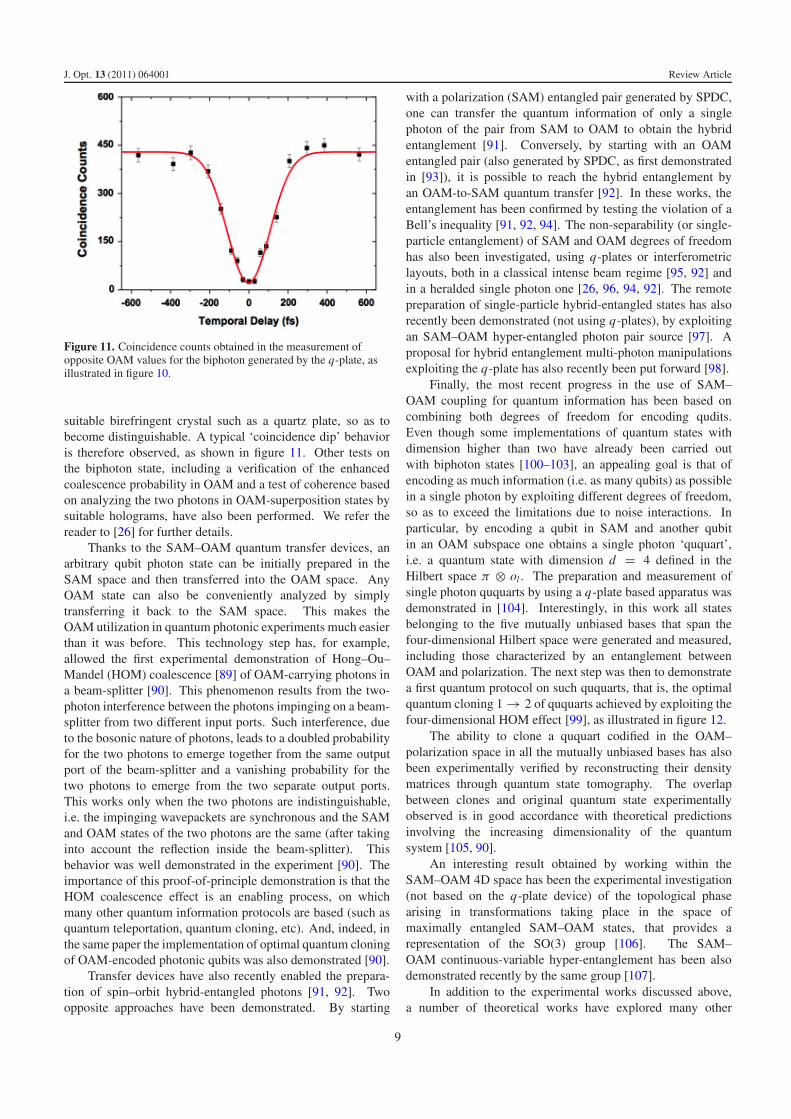
J. Opt. 13 (2011) 064001 Review Article
Figure 11. Coincidence counts obtained in the measurement ofopposite OAM values for the biphoton generated by the q-plate, asillustrated in figure 10.
suitable birefringent crystal such as a quartz plate, so as tobecome distinguishable. A typical ‘coincidence dip’ behavioris therefore observed, as shown in figure 11. Other tests onthe biphoton state, including a verification of the enhancedcoalescence probability in OAM and a test of coherence basedon analyzing the two photons in OAM-superposition states bysuitable holograms, have also been performed. We refer thereader to [26] for further details.
Thanks to the SAM–OAM quantum transfer devices, anarbitrary qubit photon state can be initially prepared in theSAM space and then transferred into the OAM space. AnyOAM state can also be conveniently analyzed by simplytransferring it back to the SAM space. This makes theOAM utilization in quantum photonic experiments much easierthan it was before. This technology step has, for example,allowed the first experimental demonstration of Hong–Ou–Mandel (HOM) coalescence [89] of OAM-carrying photons ina beam-splitter [90]. This phenomenon results from the two-photon interference between the photons impinging on a beam-splitter from two different input ports. Such interference, dueto the bosonic nature of photons, leads to a doubled probabilityfor the two photons to emerge together from the same outputport of the beam-splitter and a vanishing probability for thetwo photons to emerge from the two separate output ports.This works only when the two photons are indistinguishable,i.e. the impinging wavepackets are synchronous and the SAMand OAM states of the two photons are the same (after takinginto account the reflection inside the beam-splitter). Thisbehavior was well demonstrated in the experiment [90]. Theimportance of this proof-of-principle demonstration is that theHOM coalescence effect is an enabling process, on whichmany other quantum information protocols are based (such asquantum teleportation, quantum cloning, etc). And, indeed, inthe same paper the implementation of optimal quantum cloningof OAM-encoded photonic qubits was also demonstrated [90].
Transfer devices have also recently enabled the prepara-tion of spin–orbit hybrid-entangled photons [91, 92]. Twoopposite approaches have been demonstrated. By starting
with a polarization (SAM) entangled pair generated by SPDC,one can transfer the quantum information of only a singlephoton of the pair from SAM to OAM to obtain the hybridentanglement [91]. Conversely, by starting with an OAMentangled pair (also generated by SPDC, as first demonstratedin [93]), it is possible to reach the hybrid entanglement byan OAM-to-SAM quantum transfer [92]. In these works, theentanglement has been confirmed by testing the violation of aBell’s inequality [91, 92, 94]. The non-separability (or single-particle entanglement) of SAM and OAM degrees of freedomhas also been investigated, using q-plates or interferometriclayouts, both in a classical intense beam regime [95, 92] andin a heralded single photon one [26, 96, 94, 92]. The remotepreparation of single-particle hybrid-entangled states has alsorecently been demonstrated (not using q-plates), by exploitingan SAM–OAM hyper-entangled photon pair source [97]. Aproposal for hybrid entanglement multi-photon manipulationsexploiting the q-plate has also recently been put forward [98].
Finally, the most recent progress in the use of SAM–OAM coupling for quantum information has been based oncombining both degrees of freedom for encoding qudits.Even though some implementations of quantum states withdimension higher than two have already been carried outwith biphoton states [100–103], an appealing goal is that ofencoding as much information (i.e. as many qubits) as possiblein a single photon by exploiting different degrees of freedom,so as to exceed the limitations due to noise interactions. Inparticular, by encoding a qubit in SAM and another qubitin an OAM subspace one obtains a single photon ‘ququart’,i.e. a quantum state with dimension d = 4 defined in theHilbert space π ⊗ ol . The preparation and measurement ofsingle photon ququarts by using a q-plate based apparatus wasdemonstrated in [104]. Interestingly, in this work all statesbelonging to the five mutually unbiased bases that span thefour-dimensional Hilbert space were generated and measured,including those characterized by an entanglement betweenOAM and polarization. The next step was then to demonstratea first quantum protocol on such ququarts, that is, the optimalquantum cloning 1 → 2 of ququarts achieved by exploiting thefour-dimensional HOM effect [99], as illustrated in figure 12.
The ability to clone a ququart codified in the OAM–polarization space in all the mutually unbiased bases has alsobeen experimentally verified by reconstructing their densitymatrices through quantum state tomography. The overlapbetween clones and original quantum state experimentallyobserved is in good accordance with theoretical predictionsinvolving the increasing dimensionality of the quantumsystem [105, 90].
An interesting result obtained by working within theSAM–OAM 4D space has been the experimental investigation(not based on the q-plate device) of the topological phasearising in transformations taking place in the space ofmaximally entangled SAM–OAM states, that provides arepresentation of the SO(3) group [106]. The SAM–OAM continuous-variable hyper-entanglement has been alsodemonstrated recently by the same group [107].
In addition to the experimental works discussed above,a number of theoretical works have explored many other
9

J. Opt. 13 (2011) 064001 Review Article
Figure 12. Experimental apparatus for implementing the 1 → 2 optimal quantum cloning of polarization–OAM photon ququarts [99].
possible applications of the q-plate, or more generally ofemploying an SAM–OAM combination, in the quantuminformation field. For example, the possibility of using aq-plate for increasing the effective Shannon dimensionalityof an entangled pair of photons generated by SPDC, asa consequence of spin–orbit hyper-entanglement, has beenproposed [108]. Related works exploiting the combination ofSAM and transverse-mode degrees-of-freedom entanglementin SPDC have also been reported, showing also a link withthe field of quantum imaging [109]. A three-degrees-of-freedom single photon entanglement, involving SAM, OAM,and optical frequency, can be generated by means of rotatingq-plates, thanks to a rotational Doppler shift effect [110]. Theimplementation of so-called quantum walks in OAM space, orin hybrid SAM–OAM space, has also been investigated veryrecently [111, 112].
We notice that several single photon quantum informationprotocols involving SAM–OAM combined manipulations canalso be implemented without making recourse to q-plates,by using suitable interferometric layouts in combination withOAM manipulating devices such as spiral phase plates, Doveprisms, cylindrical lenses, etc (see, e.g., [113, 95, 114]). In allthese setups, the main working principle is the conversion ofthe polarization qubit into a path (or ‘dual rail’) qubit, and viceversa, by means of polarizing beam splitters. Although theseapproaches are fully appropriate for demonstration purposes,an obvious practical advantage of the q-plate-based setups isthat they do not require interferometric stability and may oftencarry out the entire desired quantum manipulation remainingwithin a single-beam geometry.
6. Conclusions
In summary, we have surveyed recent progress in the fieldof the orbital angular momentum of light, with specificattention given to its interaction with the optical spin angularmomentum, i.e. the light polarization. The first reported
experimental demonstrations of the possibility of inter-converting the SAM and OAM of a paraxial light beam andof single photons have stimulated an intense research effort inthe last few years. In particular, new methods of generation,control, and manipulation of the optical OAM, both in theclassical and quantum regimes, have been demonstrated usingthe recently introduced device named the q-plate. Such adevice is relatively easy to manufacture, and it is tunableand highly efficient. Its action introduces a controlledcoupling between polarization (SAM) and OAM that canbe conveniently exploited in many different ways. Thecombination of one or more q-plates and more standardpolarization or OAM devices (such as the Dove prism)in suitable schemes allows the achievement of many newoptical functionalities. In addition, a number of schemesand experiments not using the q-plate, but still exploiting theSAM and OAM of light and their reciprocal interaction, haverecently been reported.
Perhaps the most interesting potential of the combineduse of polarization and OAM of light lies in the quantuminformation field, since the multi-dimensionality of the OAMspace provides a natural possibility for implementing quditswithin single photons. The hunt for a higher quantumdimensionality of the photon is hence open!
Acknowledgments
We acknowledge the financial support of the Futureand Emerging Technologies (FET) programme within theSeventh Framework Programme for Research of the EuropeanCommission, under FET-Open grant number 255914- PHOR-BITECH.
Note added in proof. Another interesting case of optical spin–orbit couplingoccurs in the curved spacetime geometry surrounding a rotating black hole, asdemonstrated very recently in [115].
10

J. Opt. 13 (2011) 064001 Review Article
References
[1] Humblet J 1943 Sur le moment d’impulsion d’une ondeelectromagnetique Physica 10 585–603
[2] Franke-Arnold S, Allen L and Padgett M J 2008 Advances inoptical angular momentum Laser Photon. Rev. 2 299–313
[3] Van Enk S J and Nienhuis G 1994 Spin and orbital angularmomentum of photons Europhys. Lett. 25 497–501
[4] Van Enk S J and Nienhuis G 1994 Commutation rules andeigenvalues of spin and orbital angular momentum ofradiation fields J. Mod. Opt. 41 963–77
[5] Barnett S M 2002 Optical angular-momentum flux J. Opt. B:Quantum Semiclass. Opt. 4 S7–16
[6] Nieminen T A, Stilgoe A B, Heckenberg N R andRubinsztein-Dunlop H 2008 Angular momentum of astrongly focused Gaussian beam J. Opt. A: Pure Appl. Opt.10 115005
[7] Li C-F 2009 Spin and orbital angular momentum of a class ofnonparaxial light beams having a globally definedpolarization Phys. Rev. A 80 063814
[8] Barnett S M 2010 Rotation of electromagnetic fields and thenature of optical angular momentum J. Mod. Opt.57 1339–43
[9] Allen L, Beijersbergen M W, Spreeuw R J C andWoerdman J P 1992 Orbital angular momentum of lightand the transformation of Laguerre–Gaussian laser modesPhys. Rev. A 45 8185–9
[10] O’Neil A T, MacVicar I, Allen L and Padgett M J 2002Intrinsic and extrinsic nature of the orbital angularmomentum of a light beam Phys. Rev. Lett. 88 053601
[11] He H, Friese M E J, Heckenberg N R andRubinsztein-Dunlop H 1995 Direct observation of transferof angular momentum to absorptive particles from a laserbeam with a phase singularity Phys. Rev. Lett. 75 826–9
[12] Simpson N B, Dholakia K, Allen L and Padgett M 1997Mechanical equivalence of spin and orbital angularmomentum of light: an optical spanner Opt. Lett. 22 52–4
[13] Piccirillo B and Santamato E 2004 Light angular momentumflux and forces in birefringent inhomogeneous media Phys.Rev. E 69 056613
[14] Beijersbergen M W, Coerwinkel R P C, Kristensen M andWoerdman J P 1994 Helical-wavefront laser beamsproduced with a spiral phaseplate Opt. Commun. 112 321–7
[15] Bazhenov V Y, Vasnetsov M V and Soskin M S 1990 Laserbeams with screw dislocations in their wavefronts Sov.Phys.—JETP Lett. 52 429–31
Bazhenov V Y, Vasnetsov M V and Soskin M S 1990 Pis. Zh.Eksp. Teor. Fiz. 52 1037–9
[16] Bazhenov V Y, Soskin M S and Vasnetsov M V 1992 Screwdislocations in light wavefronts J. Mod. Opt. 39 985–90
[17] Basistiy I V, Bazhenov V Yu, Soskin M S and Vasnetsov M V1993 Optics of light beams with screw dislocations Opt.Commun. 103 422–8
[18] Leach J, Padgett M J, Barnett S M, Franke-Arnold S andCourtial J 2002 Measuring the orbital angular momentumof a single photon Phys. Rev. Lett. 88 257901
[19] Slussarenko S, D’Ambrosio V, Piccirillo B, Marrucci L andSantamato E 2010 The polarizing sagnac interferometer: atool for light orbital angular momentum sorting andspin–orbit photon processing Opt. Express 18 27205–16
[20] Bhandari R 1997 Polarization of light and topological phasesPhys. Rep. 281 1–64
[21] Biener G, Niv A, Kleiner V and Hasman E 2002 Formation ofhelical beams by use of Pancharatnam–Berry phase opticalelements Opt. Lett. 27 1875–7
[22] Bomzon Z, Biener G, Kleiner V and Hasman E 2002 Opt.Lett. 27 1141–3
[23] Lombard E, Drezet A, Genet C and Ebbesen T W 2010Polarization control of non-diffractive helical optical beamsthrough subwavelength metallic apertures New J. Phys.12 023027
[24] Marrucci L, Manzo C and Paparo D 2006 Opticalspin-to-orbital angular momentum conversion ininhomogeneous anisotropic media Phys. Rev. Lett.96 163905
[25] Marrucci L, Manzo C and Paparo D 2006Pancharatnam–Berry phase optical elements for wavefrontshaping in the visible domain: switchable helical modesgeneration Appl. Phys. Lett. 88 221102
[26] Nagali E, Sciarrino F, De Martini F, Marrucci L, Piccirillo B,Karimi E and Santamato E 2009 Quantum informationtransfer from spin to orbital angular momentum of photonsPhys. Rev. Lett. 103 013601
[27] Abbate G, Maddalena P, Marrucci L, Saetta L andSantamato E 1991 Photodynamical effects induced by theangular momentum of light in liquid crystals Phys. Scr.T39 389–93
[28] Santamato E, Daino B, Romagnoli M, Settembre M andShen Y R 1986 Collective rotation of molecules driven bythe angular momentum of light in a nematic film Phys. Rev.Lett. 57 2423–6
[29] Marrucci L, Abbate G, Ferraiuolo S, Maddalena P andSantamato E 1992 Self-induced stimulated light scatteringin nematic liquid crystals: theory and experiment Phys.Rev. A 46 4859–68
[30] Marrucci L and Paparo D 1997 Photoinduced molecularreorientation of absorbing liquid crystals Phys. Rev. E56 1765–72
[31] Piccirillo B, Toscano C, Vetrano F and Santamato E 2001Orbital and spin photon angular momentum transfer inliquid crystals Phys. Rev. Lett. 86 2285–8
[32] Kreuzer M, Benkler E, Paparo D, Casillo G andMarrucci L 2003 Molecular reorientation by photoinducedmodulation of rotational mobility Phys. Rev. E 68 011701
[33] Manzo C, Paparo D, Marrucci L and Janossy I 2006Light-induced rotation of dye-doped liquid crystal dropletsPhys. Rev. E 73 051707
[34] Brasselet E, Murazawa N, Misawa H and Juodkazis S 2009Optical vortices from liquid crystal droplets Phys. Rev. Lett.103 103903
[35] Janossy I 2008 Electromagnetic torque and force in axiallysymmetric liquid-crystal droplets Opt. Lett. 33 2371–3
[36] Marrucci L 2008 Generation of helical modes of light byspin-to-orbital angular momentum conversion ininhomogeneous liquid crystals Mol. Cryst. Liq. Cryst.488 148–62
[37] Karimi E, Piccirillo B, Marrucci L and Santamato E 2009Light propagation in a birefringent plate with topologicalunit charge Opt. Lett. 34 1225–7
[38] Karimi E, Piccirillo B, Nagali E, Marrucci L andSantamato E 2009 Efficient generation and sorting oforbital angular momentum eigenmodes of light bythermally tuned q-plates Appl. Phys. Lett. 94 231124
[39] Stutz M, Groblacher S, Jennewein T and Zeilinger A 2007How to create and detect n-dimensional entangled photonswith an active phase hologram Appl. Phys. Lett. 90 261114
[40] Straupe S and Kulik S 2010 Quantum optics: the quest forhigher dimensionality Nat. Photon. 4 585–6
[41] Ferrari J A, Dultz W, Schmitzer H and Frins E 2007Achromatic wavefront forming with space-variantpolarizers: application to phase singularities and lightfocusing Phys. Rev. A 76 053815
[42] Chen L X and She W L 2009 Electrically tunable andspin-dependent integer or noninteger orbital angularmomentum generator Opt. Lett. 34 178–80
[43] Ciattoni A, Cincotti G and Palma C 2003 Circularly polarizedbeams and vortex generation in uniaxial media J. Opt. Soc.Am. A 20 163–71
[44] Ciattoni A, Cincotti G and Palma C 2003 Angular momentumdynamics of a paraxial beam in a uniaxial crystal Phys. Rev.E 67 036618
11

J. Opt. 13 (2011) 064001 Review Article
[45] Brasselet E, Izdebskaya Y, Shvedov V, Desyatnikov A S,Krolikowski W and Kivshar Y S 2009 Dynamics of opticalspin–orbit coupling in uniaxial crystals Opt. Lett.34 1021–3
[46] Loussert C and Brasselet E 2010 Efficient scalar and vectorialsingular beam shaping using homogeneous anisotropicmedia Opt. Lett. 35 7–9
[47] Fadeyeva T A, Shvedov V G, Izdebskaya Y V, Volyar A V,Brasselet E, Neshev D N, Desyatnikov A S,Krolikowski W and Kivshar Y S 2010 Spatially engineeredpolarization states and optical vortices in uniaxial crystalsOpt. Express 18 10848–63
[48] Berry M V, Jeffrey M R and Mansuripur M 2005 Orbital andspin angular momentum in conical diffraction J. Opt. A:Pure Appl. Opt. 7 685–90
[49] O’Dwyer D P, Phelan C F, Rakovich Y P, Eastham P R,Lunney J G and Donegan J F 2010 Generation ofcontinuously tunable fractional optical orbital angularmomentum using internal conical diffraction Opt. Express18 16480–5
[50] Zhao Y, Edgar J S, Jeffries G D M, McGloin D and Chiu D T2007 Spin-to-orbital angular momentum conversion in astrongly focused optical beam Phys. Rev. Lett. 99 073901
[51] Adachi H, Akahoshi S and Miyakawa K 2007 Orbital motionof spherical microparticles trapped in diffraction patterns ofcircularly polarized light Phys. Rev. A 75 063409
[52] Chen L X and She W L 2008 Electro-optic ally forbidden orenhanced spin-to-orbital angular momentum conversion ina focused light beam Opt. Lett. 33 696–8
[53] Wang X-L, Chen J, Li Y, Ding J, Guo C-S andWang H-T 2010 Optical orbital angular momentum fromthe curl of polarization Phys. Rev. Lett. 105 253602
[54] Onoda M, Murakami S and Nagaosa N 2004 Hall effect oflight Phys. Rev. Lett. 93 083901
[55] Hosten O and Kwiat P 2008 Observation of the spin Halleffect of light via weak measurements Science 319 787–90
[56] Bliokh K Y, Niv A, Kleiner V and Hasman E 2008Geometrodynamics of spinning light Nat. Photon.2 748–53
[57] Bliokh K Y 2009 Geometrodynamics of polarized light: Berryphase and spin Hall effect in a gradient-index mediumJ. Opt. A: Pure Appl. Opt. 11 094009
[58] Rodrıguez-Herrera O G, Lara D, Bliokh K Y,Ostrovskaya E A and Dainty C 2010 Optical nanoprobingvia spin–orbit interaction of light Phys. Rev. Lett.104 253601
[59] Soskin M S and Vasnetsov M V 2001 Singular optics Prog.Opt. 42 219–76
[60] Soskin M S, Denisenko V and Freund I 2003 Opticalpolarization singularities and elliptic stationary points Opt.Lett. 28 1475–7
[61] Dennis M R, O’Holleran K and Padgett M J 2009 Singularoptics: optical vortices and polarization singularities Prog.Opt. 53 293–364
[62] Freund I 2010 Multitwist optical Mobius strips Opt. Lett.35 148–50
[63] Sanvitto D et al 2010 Persistent currents and quantizedvortices in a polariton superfluid Nat. Phys. 6 527–33
[64] Shelykh I A, Kavokin A V, Rubo Y G, Liew T C H andMalpuech G 2010 Polariton polarization-sensitivephenomena in planar semiconductor microcavitiesSemicond. Sci. Technol. 25 013001
[65] Nersisyan S, Tabiryan N, Steeves D M and Kimball B R 2009Opt. Express 17 11926
[66] Slussarenko S, Murauski A, Du T, Chigrinov V,Marrucci L and Santamato E 2011 Tunable liquid crystalq-plates with arbitrary topological charge Opt. Express19 4085–90
[67] Piccirillo B, D’Ambrosio V, Slussarenko S, Marrucci L andSantamato E 2010 Photon spin-to-orbital angularmomentum conversion via an electrically tunable q-plateAppl. Phys. Lett. 97 241104
[68] Mosca S, Canuel B, Karimi E, Piccirillo B, Marrucci L,De Rosa R, Genin E, Milano L and Santamato E 2010Photon self-induced spin-to-orbital conversion in aterbium–gallium–garnet crystal at high laser power Phys.Rev. A 82 043806
[69] Morikawa J, Orie A, Hashimoto T and Juodkazis S 2010Thermal and optical properties of thefemtosecond-laser-structured and stress-inducedbirefringent regions in sapphire Opt. Express 18 8300–10
[70] Brasselet E 2009 Singular optical manipulation of birefringentelastic media using nonsingular beams Opt. Lett.34 3229–31
[71] Brasselet E 2010 Spin–orbit optical cross-phase-modulationPhys. Rev. A 82 063836
[72] Calvo G F and Picon A 2007 Spin-induced angularmomentum switching Opt. Lett. 32 838–40
[73] Karimi E, Zito G, Piccirillo B, Marrucci L andSantamato E 2007 Hypergeometric-Gaussian modes Opt.Lett. 32 3053–5
[74] Vaveliuk P 2009 Nondiffracting wave properties in radiallyand azimuthally symmetric optical axis phase plates Opt.Lett. 34 3641–3
[75] Carvalho A M de M, Satiro C and Moraes F 2007Aharonov-bohm like effect for light propagating innematics with disclinations Europhys. Lett. 80 46002
[76] Padgett M J and Courtial J 1999 Poincare-sphere equivalentfor light beams containing orbital angular momentum Opt.Lett. 24 430–2
[77] Nagali E, Sciarrino F, De Martini F, Piccirillo B, Karimi E,Marrucci L and Santamato E 2009 Polarization control ofsingle photon quantum orbital angular momentum statesOpt. Express 17 18745–59
[78] Karimi E, Slussarenko S, Piccirillo B, Marrucci L andSantamato E 2010 Polarization-controlled evolution oflight transverse modes and associated Pancharatnamgeometric phase in orbital angular momentum Phys. Rev. A81 053813
[79] Coutinho dos Santos B, Souza C E R, Dechoum K andKhoury A Z 2007 Phase conjugation and adiabatic modeconversion in a driven optical parametric oscillator withorbital angular momentum Phys. Rev. A 76 053821
[80] Slussarenko S, Karimi E, Piccirillo B, Marrucci L andSantamato E 2011 Efficient generation and control ofdifferent-order orbital angular momentum states forcommunication links J. Opt. Soc. Am. A 28 61–5
[81] Slussarenko S, Karimi E, Piccirillo B, Marrucci L andSantamato E 2009 Universal unitary gate for single-photonspin–orbit four-dimensional states Phys. Rev. A 80 022326
[82] De Martini F and Sciarrino F 2005 Non-linear parametricprocesses in quantum information Prog. Quantum Electron.29 165–256
[83] Molina-Terriza G, Torres J P and Torner L 2007 Twistedphotons Nat. Phys. 3 305–10
[84] Barreiro J T, Langford N K, Peters N A and Kwiat P G 2005Generation of hyperentangled photon pairs Phys. Rev. Lett.95 260501
[85] Barreiro J T, Wei T-C and Kwiat P G 2008 Beating thechannel capacity limit for linear photonic superdensecoding Nat. Phys. 4 282–6
[86] Aolita L and Walborn S P 2007 Quantum communicationwithout alignment using multiple-qubit single-photon statesPhys. Rev. Lett. 98 100501
[87] Souza C E R, Borges C V S, Khoury A Z, Huguenin J A O,Aolita L and Walborn S P 2008 Quantum key distributionwithout a shared reference frame Phys. Rev. A 77 032345
[88] Marrucci L, Nagali E, Sciarrino F, Sansoni L, De Martini F,Piccirillo B, Karimi E and Santamato E 2010 Photonicquantum information applications of patterned liquidcrystals Mol. Cryst. Liq. Cryst. 526 108–18
[89] Hong C K, Ou Z Y and Mandel L 1987 Measurement ofsubpicosecond time intervals between two photons byinterference Phys. Rev. Lett. 59 2044–6
12

J. Opt. 13 (2011) 064001 Review Article
[90] Nagali E, Sansoni L, Sciarrino F, De Martini F, Marrucci L,Piccirillo B, Karimi E and Santamato E 2009 Optimalquantum cloning of orbital angular momentum photonqubits through Hong–Ou–Mandel coalescence Nat. Photon.3 720–3
[91] Nagali E and Sciarrino F 2010 Generation of hybridpolarization-orbital angular momentum entangled statesOpt. Express 18 18243–8
[92] Karimi E, Leach J, Slussarenko S, Piccirillo B, Marrucci L,Chen L, She W, Franke-Arnold S, Padgett M J andSantamato E 2010 Spin–orbit hybrid entanglement ofphotons and quantum contextuality Phys. Rev. A82 022115
[93] Mair A, Vaziri A, Welhs G and Zeilinger A 2001Entanglement of the angular momentum states of photonsNature 412 313–6
[94] Chen L X and She W L 2010 Single-photon spin–orbitentanglement violating a Bell-like inequality J. Opt. Soc.Am. B 27 A7–10
[95] Borges C V S, Hor-Meyll M, Huguenin J A O andKhoury A Z 2010 Bell-like inequality for the spin–orbitseparability of a laser beam Phys. Rev. A 82 033833
[96] Chen L X and She W L 2009 Teleportation of a controllableorbital angular momentum generator Phys. Rev. A80 063831
[97] Barreiro J T, Wei T-C and Kwiat P G 2010 Remotepreparation of single-photon hybrid entangled andvector-polarization states Phys. Rev. Lett. 105 030407
[98] Chen L X and She W L 2011 Hybrid entanglement swappingof photons: creating the orbital angular momentum bellstates and Greenberger–Horne–Zeilinger states Phys. Rev.A 83 012306
[99] Nagali E, Giovannini D, Marrucci L, Slussarenko S,Santamato E and Sciarrino F 2010 Experimental optimalcloning of four-dimensional quantum states of photonsPhys. Rev. Lett. 105 073602
[100] Moreva E V, Maslennikov G A, Straupe S S andKulik S P 2006 Realization of four-level qudits usingbiphotons Phys. Rev. Lett. 97 023602
[101] Bogdanov Yu I, Moreva E V, Maslennikov G A, Galeev R F,Straupe S S and Kulik S P 2006 Polarization states offour-dimensional systems based on biphotons Phys. Rev. A73 063810
[102] Vallone G, Pomarico E, De Martini F, Mataloni P andBarbieri M 2007 Experimental realization of polarizationqutrits from nonmaximally entangled states Phys. Rev. A76 012319
[103] Baek S-Y and Kim Y-H 2007 Generating entangled states oftwo ququarts using linear optical elements Phys. Rev. A75 034309
[104] Nagali E, Sansoni L, Marrucci L, Santamato E andSciarrino F 2010 Experimental generation andcharacterization of single-photon hybrid ququarts based onpolarization and orbital angular momentum encoding Phys.Rev. A 81 052317
[105] Bruß D, DiVincenzo D P, Ekert A, Fuchs C A,Macchiavello C and Smolin J A 1998 Optimal universaland state-dependent quantum cloning Phys. Rev. A57 2368–78
[106] Souza C E R, Huguenin J A O, Milman P and Khoury A Z2007 Topological phase for spin–orbit transformations on alaser beam Phys. Rev. Lett. 99 160401
[107] Coutinho dos Santos B, Dechoum K and Khoury A Z 2009Continuous-variable hyperentanglement in a parametricoscillator with orbital angular momentum Phys. Rev. Lett.103 230503
[108] Chen L X and She W L 2009 Increasing shannondimensionality by hyperentanglement of spin and fractionalorbital angular momentum Opt. Lett. 34 1855–7
[109] Caetano D P, Souto Ribeiro P H, Pardal J T C andKhoury A Z 2003 Quantum image control throughpolarization entanglement in parametric down-conversionPhys. Rev. A 68 023805
[110] Chen L X and She W L 2008 Sorting photons of differentrotational doppler shifts (rds) by orbital angular momentumof single-photon with spin–orbit-rds entanglement Opt.Express 16 14629–34
[111] Zhang P, Liu B-H, Liu R-F, Li H-R, Li F-L andGuo G-C 2010 Implementation of one-dimensionalquantum walks on spin–orbital angular momentum space ofphotons Phys. Rev. A 81 052322
[112] Hamilton C S, Gabris A, Jex I and Barnett S M 2011 Quantumwalk with a four-dimensional coin New J. Phys. 13 013015
[113] Chen L X and She W L 2009 Encoding orbital angularmomentum onto multiple spin states based on a Huffmantree New J. Phys. 11 103002
[114] Souza C E R and Khoury A Z 2010 A michelsoncontrolled-not gate with a single-lens astigmatic modeconverter Opt. Express 18 9207–12
[115] Tamburrini F, Thide B, Molina-Terriza G and Anzolin G 2011Twisting of light around rotating black holes Nature Phys.7 195–7
13