d-slam: decoupled localization and mapping for...
TRANSCRIPT

D-SLAM: Decoupled Localization and Mapping forAutonomous Robots
Zhan Wang, Shoudong Huang, and Gamini Dissanayake
ARC Centre of Excellence for Autonomous Systems (CAS)Faculty of Engineering, University of Technology, Sydney, Australia{zwang,sdhuang,gdissa }@eng.uts.edu.au
Summary. The main contribution of this paper is the reformulation of the simultaneouslocalization and mapping (SLAM) problem for mobile robots such that the mapping andlocalization can be treated as two concurrent yet separated processes: D-SLAM (decoupledSLAM). It is shown that SLAM can be decoupled into solving a non-linear static estimationproblem for mapping and a low-dimensional dynamic estimation problem for localization. Themapping problem can be solved using an Extended Information Filter where the informationmatrix is shown to be exactly sparse. A significant saving in the computational effort canbe achieved for large scale problems by exploiting the special properties of sparse matrices.An important feature of D-SLAM is that the correlation among landmarks are still kept andit is demonstrated that the uncertainty of the map landmarks monotonically decrease. Thealgorithm is illustrated through computer simulations and experiments.
1 Introduction
Simultaneous localization and mapping (SLAM) has been the subject of extensiveresearch in the past few years with a number of robotics research groups contributingto make substantial progress in this area (see for example, [1], [2], [3], [4], [5],[6], [7]and the references therein). Traditionally, SLAM uses a state vector incorporating thelocation of the robot, all the landmarks and maintains the associated full covariancematrix. This, however, leads to a heavy computational burden when solving largescale SLAM problems.
Many researchers have exploited the special structure of the covariance matrix inorder to reduce the computational effort required in SLAM. One notable result in therecent past has been that of Thrun et al. [7] which uses the Extended Information Filterto exploit the relative sparseness of the information matrix to reduce the computationaleffort required in SLAM. Frese [8] provided a proof for the approximate sparsenessof the information matrix. However, Eustice et al. [9] demonstrated that the processof sparsification proposed in [7] leads to inconsistent estimates.
In a recent development, Eustice et al. [10] show that the inclusion of the robottrajectory in the form of past robot poses in the state vector leads to an exactlysparse information matrix. The resulting Exactly Sparse Delayed State Filter (ESDSF)

2 Z. Wang, S. Huang, and G. Dissanayake
provides clear computational advantages when a view-based map representation isused. In the example presented the “map" is not represented within the state vectorand is therefore not directly updated.
Another way to reduce the computation complexity is to delete the robot in themap state vector. A variety of attempts have been made to achieve this by constructingrelative maps using the observation information. For example, Newman [3] introduceda relative map in which the map state contains the relative locations among thelandmarks. Csorba et al. [11] and Martinelli et al. [12] have used relative mapswhere the map state contains distances (and angles) among the landmarks, which areinvariants under shift and rotation. The structure of the covariance matrix is kept sparseby maintaining a state vector with redundant elements. As the relationships betweenthese elements are not enforced, for large scale problems the map becomes complexand difficult to use. However, if the constraints that enforce these relationships areapplied, the simple structure of the covariance matrix is destroyed, leading to anincreased computational complexity [3].
This paper presents an extension of the decoupled SLAM algorithm, D-SLAM,proposed by the authors in [15] [16], where SLAM is reformulated as a static estima-tion problem for mapping and a three dimensional dynamic estimation problem forlocalization. The landmark locations are maintained using either a compact relativemap [15] or an absolute Cartesian map [16]. The new formulation retains the signif-icant advantage of being able to improve the location estimates of all the landmarksfrom one local observation, yet results in an exactly sparse information matrix withthe number of nonzero elements related to the range of the sensor on board the robot.The main assumption in [15] [16] is that the robot can observe at least two previouslyseen landmarks in each observation. This paper provides a strategy to relax the aboveassumption by merging a set of observations to construct admissible measurements.An improved localization process based on a local SLAM is also presented.
The paper is organized as follows. The mapping and the localization algorithms inD-SLAM are stated in Sections 2 and 3, respectively. The computational complexityis addressed in Section 4. Section 5 provides simulation and experiments results ofD-SLAM algorithm. Section 6 concludes the paper by providing a discussion andaddressing future research directions.
2 Mapping in D-SLAM
In D-SLAM, the robot location is not included in the state vector in the mappingprocess. The state vector only contains the Cartesian coordinate of the locations ofall the observed landmarks:
X = (X1, · · · , Xn)T = (x1, y1, x2, y2, · · · , xn, yn)T . (1)
In order to generate estimates of the landmark locations the following two pro-cesses are necessary. (1) A method of recasting the observation vector such that theinformation about the landmarks that is independent of the robot location can be
D-SLAM: Decoupled Localization and Mapping for Autonomous Robots 3
extracted. (2) A new landmark initialization and update method that does not requirethe robot location. The following sections provide details of these two processes.
2.1 Recasting the measurement vector
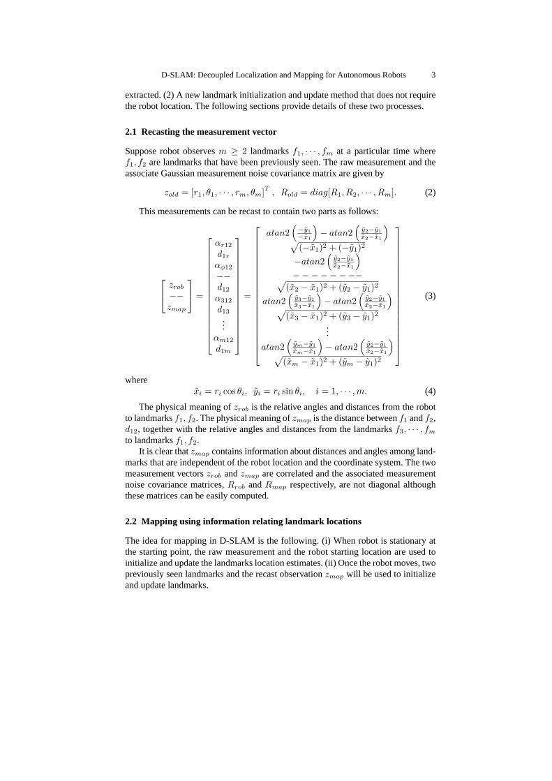
Suppose robot observesm ≥ 2 landmarksf1, · · · , fm at a particular time wheref1, f2 are landmarks that have been previously seen. The raw measurement and theassociate Gaussian measurement noise covariance matrix are given by
zold = [r1, θ1, · · · , rm, θm]T , Rold = diag[R1, R2, · · · , Rm]. (2)
This measurements can be recast to contain two parts as follows:
zrob
−−zmap
=
αr12
d1r
αφ12
−−d12
α312
d13
...αm12
d1m
=
atan2(−y1−x1
)− atan2
(y2−y1x2−x1
)√
(−x1)2 + (−y1)2
−atan2(
y2−y1x2−x1
)
−−−−−−−−√(x2 − x1)2 + (y2 − y1)2
atan2(
y3−y1x3−x1
)− atan2
(y2−y1x2−x1
)√
(x3 − x1)2 + (y3 − y1)2...
atan2(
ym−y1xm−x1
)− atan2
(y2−y1x2−x1
)√
(xm − x1)2 + (ym − y1)2
(3)
wherexi = ri cos θi, yi = ri sin θi, i = 1, · · · ,m. (4)
The physical meaning ofzrob is the relative angles and distances from the robotto landmarksf1, f2. The physical meaning ofzmap is the distance betweenf1 andf2,d12, together with the relative angles and distances from the landmarksf3, · · · , fm
to landmarksf1, f2.It is clear thatzmap contains information about distances and angles among land-
marks that are independent of the robot location and the coordinate system. The twomeasurement vectorszrob andzmap are correlated and the associated measurementnoise covariance matrices,Rrob andRmap respectively, are not diagonal althoughthese matrices can be easily computed.
2.2 Mapping using information relating landmark locations
The idea for mapping in D-SLAM is the following. (i) When robot is stationary atthe starting point, the raw measurement and the robot starting location are used toinitialize and update the landmarks location estimates. (ii) Once the robot moves, twopreviously seen landmarks and the recast observationzmap will be used to initializeand update landmarks.

4 Z. Wang, S. Huang, and G. Dissanayake
After the robot moves, the measurement model is (assumef1, f2 are previouslyseen landmarks, recall that the state vectorX is given in (1))
zmap = [d12, α312, d13, · · · , αm12, d1m]T = Hmap(X) + wmap (5)
whereHmap(X) is given by the last2m− 3 formulas in equation (3) by substitutingxi, yi with the absolute locations of the landmarksxi, yi (i = 1, · · · ,m). wmap isthe new measurement noise whose covariance matrixRmap can be computed by (2),(3), and (4).
The mapping problem can now be solved as a linearized minimum mean squareerror problem. Leti(k) represent information vector andI(k) be the associatedinformation matrix. The state vector and the information vector are related through
i(k) = I(k)X(k). (6)
The procedure for using the measurementszmap to update the information vectorand the information matrix is as follows:
I(k + 1) = I(k) +∇HTmapR
−1map∇Hmap
i(k + 1) = i(k) +∇HTmapR
−1map[zmap(k + 1)−Hmap(X(k)) +∇HmapX(k)]
(7)where∇Hmap is the Jacobian of the functionHmap with respect to all the statesevaluated on the current state estimationX(k).
2.3 Construction of admissible measurements
To be admissible in the mapping algorithm outlined in the previous section, observa-tion vectors need to satisfy the following condition.
Definition. An observation made at a particular point is called admissible if itcontains at least two previously seen landmarks.
Figure 1 shows an example where robot observes two old landmarksf1, f2 andtwo new landmarksf3, f4 at pointP1, but it only observes one landmarkf5 at pointP2 and one other landmarkf6 at pointP3. Later on at pointP4, it observes landmarksf5, f6, f7. Thus the observations atP2 and P3 are not admissible. It is, however,possible to combine the measurements made from different points to generate newadmissible measurements as follows. Once it is detected that the observation at pointP2 is not admissible, the update to the map using the observation information fromP1 will be removed. Then a virtual observation fromP2 to f1, f2, f3, f4 will beconstructed using the observation fromP1 to f1, f2, f3, f4 and an estimate of therelative motion of the robot fromP1 to P2 (Figure 1). The uncertainty associatedwith this composite observation can be computed using the relevant observationequations and the process and observation uncertainties. The mapping process willproceed as if landmarksf1, f2, f3, f4, f5 are observed fromP2 and no observationis made atP1. This process is repeated wherever an inadmissible observation isencountered, for example atP3. This strategy allows D-SLAM to function where acluster of landmarks are separated from another cluster of landmarks by a region of"featureless" terrain.

D-SLAM: Decoupled Localization and Mapping for Autonomous Robots 5
Fig. 1. Construct admissible measurement from the raw measurements
3 Localization in D-SLAM
In the localization process of D-SLAM, estimates from two approaches are combinedto obtain an estimate for the robot location (and local landmark locations). Oneapproach is to use a local traditional SLAM. The other is to use the current observationand the map generated in the previous step to solve the kidnapped robot problem.Figure 2 shows a flow-chart illustrating the localization process.
Fig. 2. Flow chat of localization and mapping process in D-SLAM
Suppose that robot observes landmarksf1, · · · , fm at time k, among whichf1, · · · , fm1 , m1 ≤ m are landmarks that have been previously seen. The state vectorin D-SLAM localization contains the location of the robot and these previously seenlandmarksf1, · · · , fm1 .
Xloc(k) = (Xr(k), X1, · · · , Xm1)T . (8)
An estimate ofX1, · · · , Xm1 and the associated covariance matrix are availablefrom the map obtained at timek−1. These together with the part of the measurementvectorzold that involves landmarksf1, · · · , fm1 ,

6 Z. Wang, S. Huang, and G. Dissanayake
zloc = (r1, θ1, · · · , rm1 , θm1)T = Hloc(Xr(k), X1, · · · , Xm1) + wloc, (9)
can be used to estimateXloc(k). HereHloc contains2m1 typical range and bearingobservation functions. The estimate ofXloc(k) is a low dimensional linearized mini-mum mean square error estimation problem. This approach does not make use of theprocess model and therefore is clearly sub-optimal.
The alternative is to use a local traditional SLAM process to estimateXloc(k),where only the landmarks in the vicinity of the robot are retained in the state vector.Landmarks are removed from the state vector once they are not visible from the robot.When a previously deleted landmark is re-observed, the landmark is reinitialised andis treated as a new landmark. This is effectively a SLAM-aided dead reckoningprocess which provides a much better robot location estimate than that obtainedusing dead-reckoning alone.
Which of the two estimates is more accurate depends on the prevailing circum-stances. Local SLAM estimate is optimal, until the robot closes a loop by revisiting apreviously traversed region of the map. The kidnapped robot solution will be superiorwhen loop closures are present. Fusing the outcomes of the two localization processeswill result in a better estimate. However, these two estimates for the robot location arecorrelated. Therefore, it is necessary to combine these estimates using a strategy, forexample covariance intersection (CI) [14], that facilitates combining two correlatedpieces of information, when the extent of correlation itself is unknown (see Figure2).
The robot location computed is sub-optimal and is correlated to the map. Thesecorrelations do not affect the mapping process as the observation used for mapping,zmap, is independent of the robot location. However, as information about the robotlocation is not exploited in the mapping process, estimate of the map will also besuboptimal.
4 Computational complexity
A key feature of D-SLAM is that the information matrix in the mapping process isexactly sparse, and this reduces the computation cost significantly.
Since the measurementzmap only involves a small fraction of the total number oflandmarks, the matrix∇HT
mapR−1map∇Hmap in (7) is sparse with the elements relating
to the landmarks that are not present in the measurement vector being exactly zero.
This can be easily seen by the fact∇Hmap =[
∂Hmap
∂X1, · · · , ∂Hmap
∂Xm, 0, · · · , 0
].
In a typical sensor where the sensor range is finite, the observations only relatelandmarks that are close to each other. Therefore, if landmarki and landmarkj arenot visible simultaneously from the robot, the measurementzmap will never containboth fi and fj . As the information matrix update involves a simple addition, theelements relating toi andj in the information matrix will remain exactly zero. Thus,in a large scale map, a significant portion of the information matrix will be exactlyzero, resulting in an exactly sparse information matrix.

D-SLAM: Decoupled Localization and Mapping for Autonomous Robots 7
Let N be the size of the map. The storage requirement isO(N) because theinformation matrix is sparse with non-zero elementsO(N). Localization step in D-SLAM requires updating a state vector containing only constant number of elements,thus computational cost isO(1). Mapping in D-SLAM is formulated in the informa-tion form where the update step is aO(1) time process and the prediction step, thecomputationally demanding stage of an information filter, does not exist. For dataassociation, locations as well as the uncertainty of the landmarks in the vicinity ofthe robot are required. The vicinity here is defined in terms of the range of the sensorused and contains onlyO(1) landmarks.
The major computational cost of D-SLAM is due to the need for recovering thestate vector containing the landmark locations and the related parts of the covariancematrix. The state vector can be recovered by solving a sparse linear equation (6). Thedesired columns of the covariance matrix can also be obtained by solving a constantnumber of sparse linear equations. Since good initial guesses are available for thelinear equations (the previous estimation is a good initial guess for state vector, zerovectors are good initial guesses for the columns of covariance matrix), few iterationsare enough for iterative method (for example, Preconditional Conjugate Gradientmethod) to converge to the solutions. Thus the computation cost for the recovery isO(N). The multigrid algorithm proposed in [13] may also be an efficient method forthe recovery. Overall cost of D-SLAM is, therefore,O(N).
5 Evaluation of D-SLAM
5.1 Experimental Evaluation with a Pioneer robot in an office environment
The Pioneer 2 DX robot was used for the experimental implementation. This robot isequipped with a laser range finder with a field of view of 180 degrees and an angularresolution of 0.5 degree. Twelve laser reflectors were placed in a8 × 8m2 area andthe Player software was used to control the robot and collect sensor data.
Matlab implementation of D-SLAM was used to process the data and computethe robot and landmark locations. Nearest neighbour algorithm was used for dataassociation and for comparison, robot and landmark locations were also obtainedusing the traditional full SLAM algorithm. The results are presented in Figure 3.Although the robot localization estimates are conservative compared to traditionalSLAM, the new algorithm provided a much superior estimate to that presented in[16].
5.2 Evaluation of D-SLAM in simulation with a large number of landmarks
A more complex simulation experiment with larger number of landmarks was con-ducted to further evaluate D-SLAM and demonstrate its properties. The environmentused is a 40 meter square with 196 landmarks arranged in uniformly spaced rowsand columns. The robot starts from the left bottom corner of the square and followsa random trajectory, revisiting many landmarks and closing many loops as seen in

8 Z. Wang, S. Huang, and G. Dissanayake
−4 −3 −2 −1 0 1 2 3 4 5 6−4
−3
−2
−1
0
1
2
3
4
5
6
X(m)
Y(m
)
Loop: 485
(a)
0 20 40 60 80 100 120 140 160−0.2
−0.1
0
0.1
0.2
Err
or in
X(m
)
0 20 40 60 80 100 120 140 160−0.2
−0.1
0
0.1
0.2
Err
or in
Y(m
)
0 20 40 60 80 100 120 140 160−0.1
−0.05
0
0.05
0.1
Err
or in
Phi
(rad
)
Time(sec)
(b)
0 20 40 60 80 100 120 140 1600
0.05
0.1
0.15
0.2
Err
or in
X(m
)
0 20 40 60 80 100 120 140 1600
0.05
0.1
0.15
0.2
Err
or in
Y(m
)
0 20 40 60 80 100 120 140 1600
0.02
0.04
0.06
Err
or in
Phi
(m)
Time(sec)
(c)
0 20 40 60 80 100 120 140 1600
0.02
0.04
0.06
0.08
0.1
Est
imat
ion
erro
r in
X(m
)
0 20 40 60 80 100 120 140 1600
0.02
0.04
0.06
0.08
0.1
Est
imat
ion
erro
r in
Y(m
)
Time(sec)
(d)
Fig. 3.D-SLAM implementation: (a) Map obtained by D-SLAM; (b) Robot location estimationerror; (c)2σ bounds of robot location estimation (solid line is from D-SLAM; dashed line isfrom traditional SLAM); (d)2σ bounds of landmark 9 estimation (solid line is from D-SLAM;dashed line is from traditional SLAM).
Figure 4(a). A sensor with a field of view of 180 degrees and a range of 5 metersis simulated to generate relative range and bearing measurements between the robotand the landmarks.
Figure 4(b) shows the estimation error and the associated 95% confidence levelsfor one landmark far away from the robot initial location. It is clear that the estimatesare consistent. Figure 4(c) shows all the non-zero elements of the information matrixin black after reordering. It is clear that this matrix is sparse as there are 7312non-zero elements and 68864 exactly zero elements. The blocks diagonal terms aredue to landmarks in close vicinity observed together and the off diagonal terms aredue to loop closures where a previously seen landmark is re-observed some timelater. Reordering the information matrix, so that indices of the nearby landmarks areadjacent, results in the banded matrix. This matrix demonstrates the fact that only thenearby landmarks are linked in the information matrix.

D-SLAM: Decoupled Localization and Mapping for Autonomous Robots 9
0 5 10 15 20 25 30 35 40
0
5
10
15
20
25
30
35
40
X(m)
Y(m
)
(a)
0 200 400 600 800 1000 1200 1400 1600 1800 2000−0.4
−0.3
−0.2
−0.1
0
0.1
0.2
0.3
Est
imat
ion
erro
r of
X(m
)
0 200 400 600 800 1000 1200 1400 1600 1800 2000−0.4
−0.3
−0.2
−0.1
0
0.1
0.2
0.3
Est
imat
ion
erro
r of
Y(m
)
Time(sec)
(b)
0 50 100 150 200 250
0
50
100
150
200
250
nz = 7312
(c)
Fig. 4.D-SLAM simulations: (a) Map obtained by D-SLAM; (b) Estimation error of a landmarkfar away from robot starting location, and its 95% confidence limit; (c) Sparse informationmatrix obtained by D-SLAM after reordering (7312 non-zero elements and 68864 exactly zeroelements).
6 Discussion and Conclusions
In this paper, a new decoupled SLAM algorithm: D-SLAM, is described. While thelocalization and mapping are performed simultaneously, mapping and localization areseparated processes. The significant advantages gained are that there is no predictionstep for the mapping, the information matrix associated with mapping is exactlysparse and only the landmarks that are in the close vicinity are linked through theinformation matrix. This results in anO(N) SLAM algorithm whereN is the numberof landmarks.
Although the robot location is not incorporated in the state vector used in mapping,correlations between the landmarks are still preserved. Thus the location estimatesof all the landmarks are improved using information from one local observation.
In D-SLAM, however, the knowledge about the robot location is not exploitedin the mapping process and this results in some information loss. An analysis basedon a linear one-dimensional model as well as 2-D simulations demonstrated that theinformation loss depends on the ratio between the sensor noise and the process noise.The smaller the ratio, the less amount of information lost. Further analytical work toquantify the extent of information loss is currently underway.
Additional work is necessary to further reduce the computation effort by exploringthe possibilities of using D-SLAM in conjunction with the submap idea (e.g. [5]).Investigations in these directions together with a large scale experiment using VictoriaPark data set [17] are currently in progress. Further work is required to compareD-SLAM with the recent developments in view-based SLAM [10]. In view-basedSLAM the state vector consists of robot poses whereas the map is obtained throughregistration of successive observation sets. In D-SLAM, the map is represented in thestate vector and one localization estimate is generated by registering the robot in themap. Both approaches result in significant computational advantages at the expenseof some information loss. Examination of the relationship between D-SLAM with

10 Z. Wang, S. Huang, and G. Dissanayake
the FastSLAM algorithm where particles are used to represent the possible robottrajectories will also be interesting.
Acknowledgment
This work is supported by the ARC Centre of Excellence programme, funded by theAustralian Research Council (ARC) and the New South Wales State Government.
References
1. Dissanayake G, Newman P, Clark S, Durrant-Whyte H, Csorba M (2001) “A solutionto the simultaneous localization and map building (SLAM) problem,”IEEE Trans. onRobotics and Automation, vol. 17, pp. 229–241
2. Guivant JE, Nebot EM (2001) “Optimization of the simultaneous localization and mapbuilding (SLAM) algorithm for real time implementation,”IEEE Trans. on Robotics andAutomation, vol. 17, pp. 242–257
3. Newman P (2000) On the Structure and Solution of the Simultaneous Localization andMap Building Problem, PhD thesis, Australian Centre of Field Robotics, University ofSydney, Sydney
4. Castellanos JA, Neira J, Tardos JD (2001) “Multisensor fusion for simultaneous localiza-tion and map building,”IEEE Trans. on Robotics and Automation, vol. 17, 908–914
5. Bosse M, Newman P, Leonard JJ, and Teller S (2004) “SLAM in Large-scale CyclicEnvironments using the Atlas Framework",International Journal on Robotics Research,vol. 23 (12), pp. 1113–1139
6. Folkesson J, Christensen HI (2004) “Graphical SLAM - A Self-Correcting Map,”InProceedings IEEE International Conference on Robotics and Automation (ICRA), LA,New Orleans, pp. 383–390
7. Thrun S, Liu Y, Koller D, Ng AY, Ghahramani Z, Durrant-Whyte H (2004) “SimultaneousLocalization and Mapping with Sparse Extended Information Filters,”International J. ofRobotics Research, vol. 23, pp. 693–716
8. Frese U (2005) “A Proof for the Approximate Sparsity of SLAM Information Matrices,”In Proceedings IEEE International Conference on Robotics and Automation (ICRA),Barcelona, Spain, pp. 331–337
9. Eustice RM, Walter M, Leonard JJ (2005) “Sparse Extended Information Filters: In-sights into Sparsification,”In Proceedings of 2005 IEEE/RSJ International Conference onIntelligent Robots and Systems (IROS), Edmonton, Alberta, Canada, August, pp. 641–648
10. Eustice RM, Singh H, Leonard JJ (2005) “Exactly sparse delayed-state filters,”In Proceed-ings of IEEE International Conference on Robotics and Automation (ICRA), Barcelona,Spain, pp. 2428–2435
11. Csorba M, Uhlmann JK, Durrant-Whyte H (1997) “A suboptimal algorithm for automaticmap building,”In Proceedings of 1997 American Control Conference, USA, pp. 537–541
12. Martinelli A, Tomatics N, Siegwart R (2004) “Open challenges in SLAM: An optimalsolution based on shift and rotation invariants,”In Proceedings of IEEE InternationalConference on Robotics and Automation (ICRA), LA, New Orleans, pp. 1327–1332
13. Frese U, Larsson P, Duckett T (2005) “A Multigrid Algorithm for Simultaneous Localiza-tion and Mapping,”IEEE Transactions on Robotics, vol. 21 (2), pp. 1–12

D-SLAM: Decoupled Localization and Mapping for Autonomous Robots 11
14. Chen L, Arambel PO, Mehra RK (2002) “Estimation under unknown correlation: co-variance intersection revisited,”IEEE Transactions on Automatic Control, 47(11), pp.1879–1882
15. Wang Z, Huang S, Dissanayake G (2005) “Decoupling Localization and Mapping inSLAM Using Compact Relative Maps,”In Proceedings of IEEE/RSJ International Con-ference on Intelligent Robots and Systems (IROS), Edmonton, Alberta, Canada, pp. 1041–1046
16. Wang Z, Huang S, Dissanayake G (2005) “Implementation Issues and ExperimentalEvaluation of D-SLAM,”In Proceedings of the 5th International Conference on Field andService Robotics (FSR), Port Douglas, Australia. pp. 153–164
17. Nebot EM, UTE Experimental Data from Victoria Park, available onlinehttp://www.acfr.usyd.edu.au/homepages/academic/enebot/experimentaldataute.htm