d-300 / d-500 / d-700 - gen-automatika.ru · d-300 / 500 / 700 modbus application manual v5.6...
TRANSCRIPT

D-300 / 500 / 700 Modbus Application Manual V5.6 (10.09.2015)
- 1 -
MODBUS APPLICATION MANUAL
D-300 / D-500 / D-700
D-300 / 500 / 700 Modbus Application Manual V5.6 (10.09.2015)
- 2 -
Any unauthorized use or copying of the contents or any part of this document is prohibited. This applies in particular to trademarks, model denominations, part numbers and drawings.
This document describes minimum required details for the successfull interfacing of the D-500/700 family units to 3rd party Modbus and Modbus-TCP/IP based applications.
Follow carefully advices given in the document. These are often good practices for the installation of genset control units which reduce future issues.
For all technical queries please contact Datakom at below e-mail address:
This document will apply to both Modbus through RS-485 and Modbus-TCP/IP communications.
FILENAME DESCRIPTION
500-USER D-500 D-700 User Manual
500-Ethernet Configuration Ethernet Configuration Guide for D-500 D-700
500-GSM Configuration GSM Configuration Guide for D-500 D-700
REVISION DATE AUTHOR DESCRIPTION
01 10.07.2012 MH First issue, firmware version 2.8
02 01.10.2012 MH Updated for firmware version 3.2
03 10.09.2015 MH Updated for firmware version 5.6 and D-300 product
CAUTION: Potential risk of injury or death.
WARNING: Potential risk of malfunction or material damage.
ATTENTION: Useful hints for the understanding of device operation.
SCOPE OF THIS DOCUMENT
TERMINOLOGY
REVISION HISTORY
RELATED DOCUMENTS
ABOUT THIS DOCUMENT
COPYRIGHT NOTICE
D-300 / 500 / 700 Modbus Application Manual V5.6 (10.09.2015)
- 3 -
The Modbus communication is widely used in the connection of industrial control units to various management systems for remote monitoring and control. It has begun the basic industry standard in the last decades. D-series units offer the possibility of MODBUS communication through below carriers:
-RS485 serial port, with adjustable baud rate between 2400 and 115200 bauds -RS232 serial port, with adjustable baud rate between 2400 and 57600/115200 bauds -MODBUS-TCP/IP through Ethernet port (10/100Mb) -MODBUS-TCP/IP through GSM-GPRS modem. (85kb/s)
Detailed description about the MODBUS protocol is found in the document “Modicon Modbus Protocol Reference Guide”. This document may be downloaded at: www.modbus.org/docs/PI_MBUS_300.pdf Detailed description about the MODBUS-TCP/IP protocol is found in the document “MODBUS APPLICATION PROTOCOL SPECIFICATION”. This document may be downloaded at: http://www.modbus.org/docs/Modbus_Application_Protocol_V1_1b.pdf
The MODBUS properties of the unit are: -Data transfer mode: RTU -Serial data: selectable baud rate, 8 bit data, no parity, 1 bit stop -Modbus-TCP/IP: Ethernet 10/100Mb or GPRS Class 12. -Supported functions: -Function 3 (Read multiple registers) -Function 6 (Write single register)
-Function 16 (Write multiple registers) Each register consists of 2 bytes (16 bits). A larger data structure will contain multiple registers.
The Modbus communications requires a slave address to be assigned to each device in the Modbus network. This address ranges between 1 and 240 and allows the addressing of different slave devices in the same network.
Devices using Modbus-TCP/IP with different IP or port addresses may use any slave address. It is advised to set these slave addresses to the default setting which is 1.
Each device in the same RS-485 serial network must be assigned a different slave address. Otherwise the Modbus communications will not be performed.
MODBUS CONFIGURATION
MODBUS COMMUNICATION BASICS
D-300 / 500 / 700 Modbus Application Manual V5.6 (10.09.2015)
- 4 -
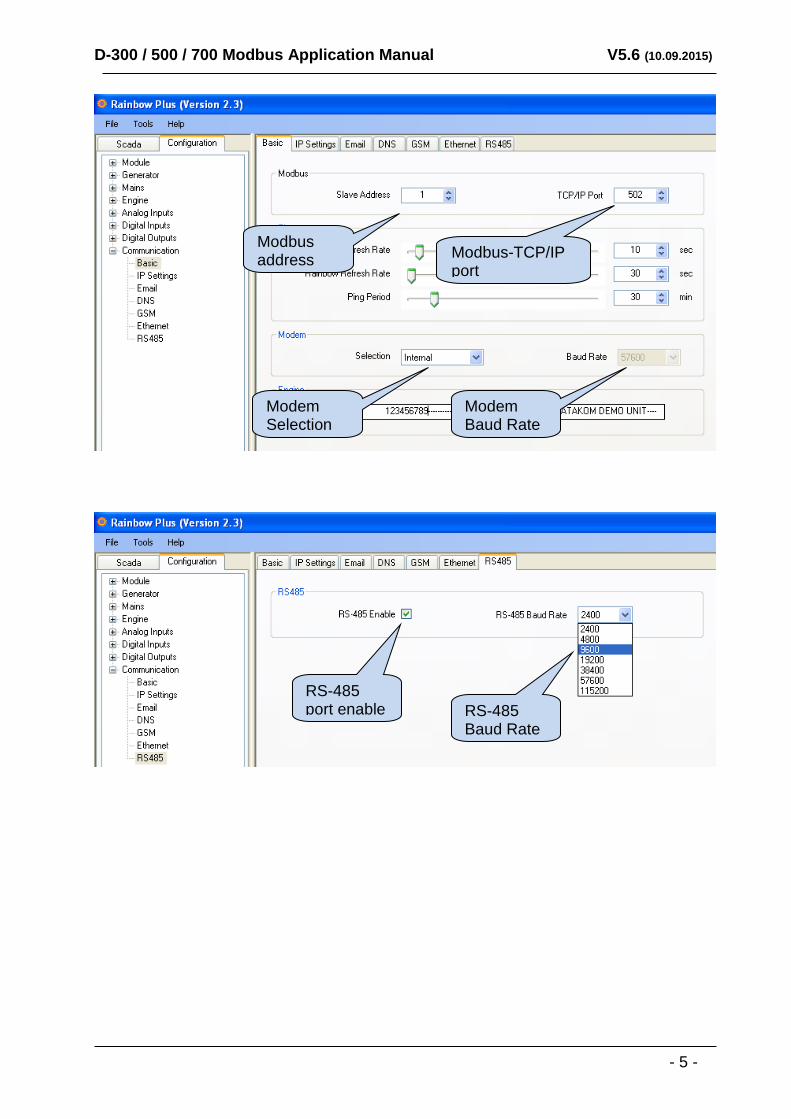
Modbus Slave Address: may be set between 1 and 240 RS-485 Enable: must be set to 1 (or checkbox enabled) RS-485 Baud Rate: selectable between 2400 and 115200 bauds. All devices in the same network must use the same Baud Rate. The complete RS-485 and RS-232 port specifications are found in the D-500/700 User Manual. Selecting a higher baud rate will allow faster communication, but will reduce the communication distance. Selecting a lower baud rate will increase the communication distance, but will cause slower response times. Typically 9600 bauds will allow 1200m distance with special balanced 120 ohms low capacitance cable.
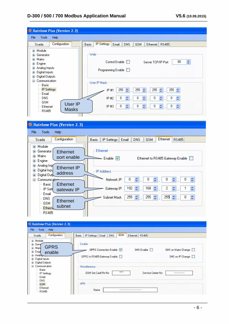
Modbus Slave Address: may be set between 1 and 240. If only one unit is available in the same IP address, it is advised to keep the default address (1). Ethernet Enable: This parameter should be set to 1 (or checked) in order to enable the ethernet port. Modbus TCP/IP Port: The usual setting is 502. However the unit is able to work on any port address. User IP Mask: There are 3 mask registers available. The use of the registers are emphasized in the D-500/700 User Manual. Please set the first mask as 255.255.255.0 for the proper operation. Ethernet Network IP: May be left as 0.0.0.0 for automatic address claim or set to a value in order to claim a defined address. Ethernet Gateway IP: Should be set in accordance with your local switch configuration. Ethernet Subnet Mask: Should be set in accordance with your local switch configuration. The complete Ethernet port specifications are found in the D-500/700 User Manual. Please rewiev the document Ethernet Configuration Guide for D-500/700 for more details about the ethernet port setup.
Modbus Slave Address: may be set between 1 and 240. If only one unit is available in the same IP address, it is advised to keep the default address (1). Modem Selection: Internal or external following your configuration. Modem Baud Rate: Selectable only for external modem. 115200 bauds advised. Selecting a lower baud rate will slow down communication between the controller and the modem. GPRS Connection Enable: This parameter should be set to 1 (or checked). Modbus TCP/IP Port: Set this value to 80. User IP Mask: There are 3 mask registers available. The use of the registers are emphasized in the D-500/700 User Manual. Please set the first mask as 255.255.255.0 for the proper operation.
Parameters required for Modbus-TCP/IP through GSM_GPRS Modem
Parameters required for Modbus-TCP/IP through Ethernet port
Parameters required for RS-485/232 Modbus operation
D-300 / 500 / 700 Modbus Application Manual V5.6 (10.09.2015)
- 5 -
Modbus address
RS-485 port enable RS-485
Baud Rate
Modbus-TCP/IP port
Modem Selection
Modem Baud Rate
D-300 / 500 / 700 Modbus Application Manual V5.6 (10.09.2015)
- 6 -
User IP Masks
Ethernet port enable
Ethernet IP address
Ethernet gateway IP
Ethernet subnet mask
GPRS enable
D-300 / 500 / 700 Modbus Application Manual V5.6 (10.09.2015)
- 7 -
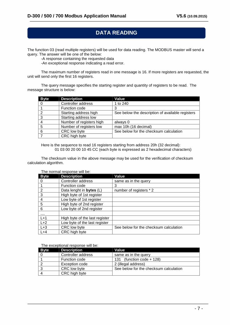
The function 03 (read multiple registers) will be used for data reading. The MODBUS master will send a query. The answer will be one of the below: -A response containing the requested data -An exceptional response indicating a read error. The maximum number of registers read in one message is 16. If more registers are requested, the unit will send only the first 16 registers. The query message specifies the starting register and quantity of registers to be read. The message structure is below:
Byte Description Value
0 Controller address 1 to 240
1 Function code 3
2 Starting address high See below the description of available registers
3 Starting address low
4 Number of registers high always 0
5 Number of registers low max 10h (16 decimal)
6 CRC low byte See below for the checksum calculation
7 CRC high byte
Here is the sequence to read 16 registers starting from address 20h (32 decimal): 01 03 00 20 00 10 45 CC (each byte is expressed as 2 hexadecimal characters) The checksum value in the above message may be used for the verification of checksum calculation algorithm. The normal response will be:
Byte Description Value
0 Controller address same as in the query
1 Function code 3
2 Data lenght in bytes (L) number of registers * 2
3 High byte of 1st register
4 Low byte of 1st register
5 High byte of 2nd register
6 Low byte of 2nd register
....
L+1 High byte of the last register
L+2 Low byte of the last register
L+3 CRC low byte See below for the checksum calculation
L+4 CRC high byte
The exceptional response will be:
Byte Description Value
0 Controller address same as in the query
1 Function code 131 (function code + 128)
2 Exception code 2 (illegal address)
3 CRC low byte See below for the checksum calculation
4 CRC high byte
DATA READING
D-300 / 500 / 700 Modbus Application Manual V5.6 (10.09.2015)
- 8 -
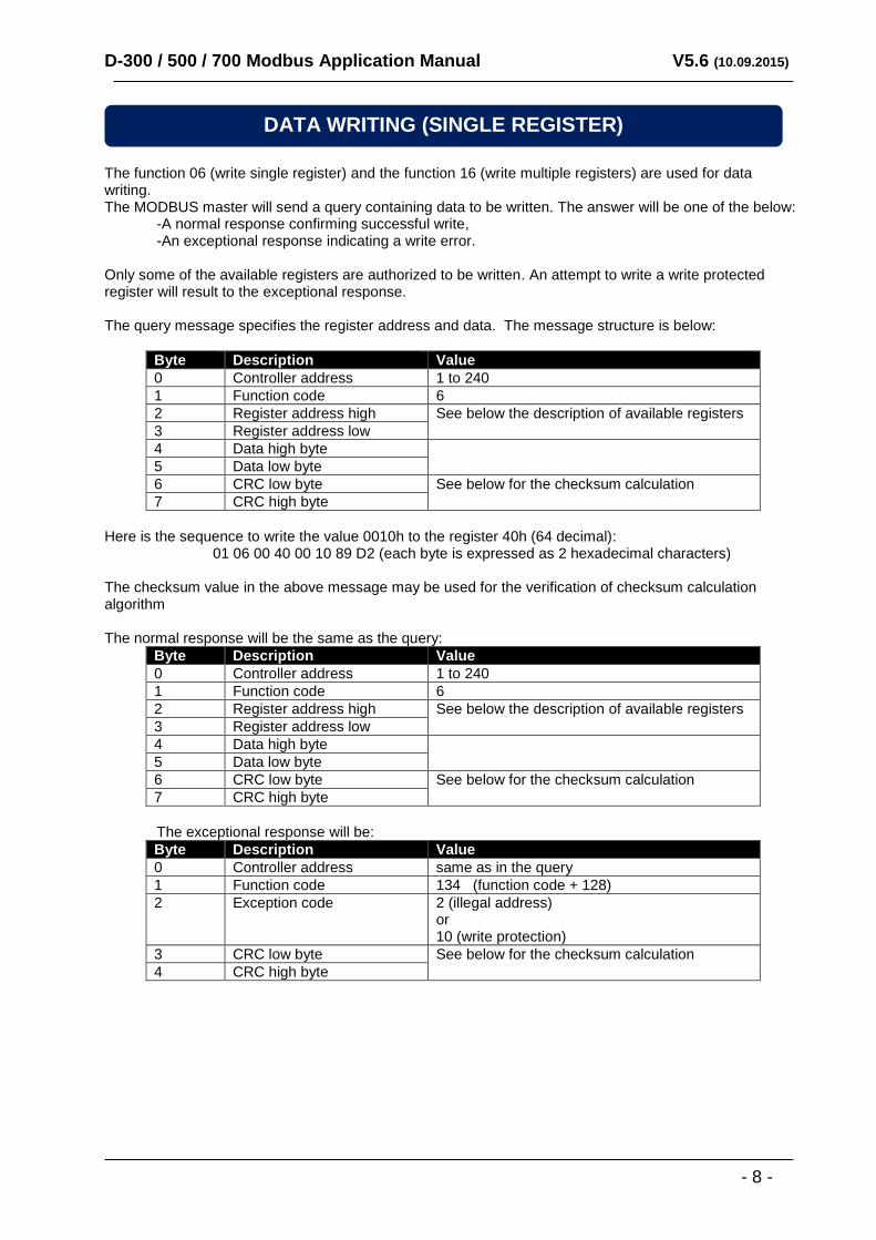
The function 06 (write single register) and the function 16 (write multiple registers) are used for data writing. The MODBUS master will send a query containing data to be written. The answer will be one of the below: -A normal response confirming successful write, -An exceptional response indicating a write error. Only some of the available registers are authorized to be written. An attempt to write a write protected register will result to the exceptional response. The query message specifies the register address and data. The message structure is below:
Byte Description Value
0 Controller address 1 to 240
1 Function code 6
2 Register address high See below the description of available registers
3 Register address low
4 Data high byte
5 Data low byte
6 CRC low byte See below for the checksum calculation
7 CRC high byte
Here is the sequence to write the value 0010h to the register 40h (64 decimal): 01 06 00 40 00 10 89 D2 (each byte is expressed as 2 hexadecimal characters) The checksum value in the above message may be used for the verification of checksum calculation algorithm The normal response will be the same as the query:
Byte Description Value
0 Controller address 1 to 240
1 Function code 6
2 Register address high See below the description of available registers
3 Register address low
4 Data high byte
5 Data low byte
6 CRC low byte See below for the checksum calculation
7 CRC high byte
The exceptional response will be:
Byte Description Value
0 Controller address same as in the query
1 Function code 134 (function code + 128)
2 Exception code 2 (illegal address) or 10 (write protection)
3 CRC low byte See below for the checksum calculation
4 CRC high byte
DATA WRITING (SINGLE REGISTER)
D-300 / 500 / 700 Modbus Application Manual V5.6 (10.09.2015)
- 9 -
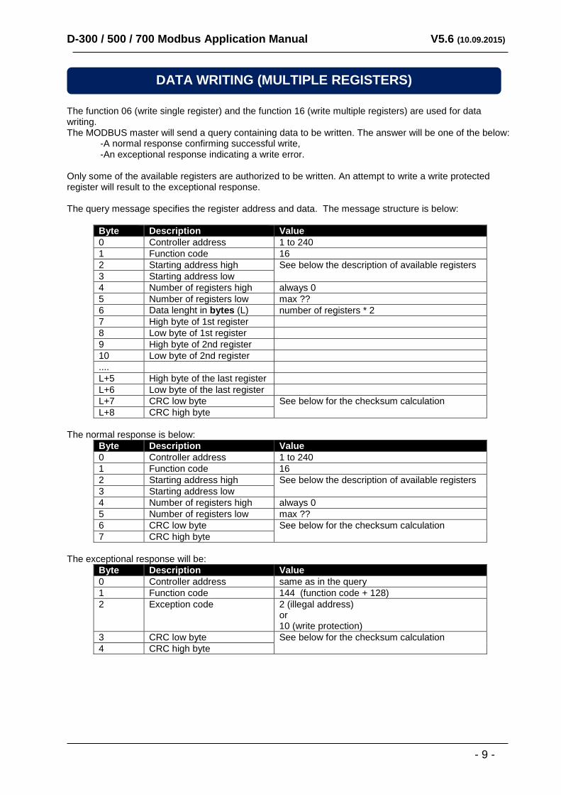
The function 06 (write single register) and the function 16 (write multiple registers) are used for data writing. The MODBUS master will send a query containing data to be written. The answer will be one of the below: -A normal response confirming successful write, -An exceptional response indicating a write error. Only some of the available registers are authorized to be written. An attempt to write a write protected register will result to the exceptional response. The query message specifies the register address and data. The message structure is below:
Byte Description Value
0 Controller address 1 to 240
1 Function code 16
2 Starting address high See below the description of available registers
3 Starting address low
4 Number of registers high always 0
5 Number of registers low max ??
6 Data lenght in bytes (L) number of registers * 2
7 High byte of 1st register
8 Low byte of 1st register
9 High byte of 2nd register
10 Low byte of 2nd register
....
L+5 High byte of the last register
L+6 Low byte of the last register
L+7 CRC low byte See below for the checksum calculation
L+8 CRC high byte
The normal response is below:
Byte Description Value
0 Controller address 1 to 240
1 Function code 16
2 Starting address high See below the description of available registers
3 Starting address low
4 Number of registers high always 0
5 Number of registers low max ??
6 CRC low byte See below for the checksum calculation
7 CRC high byte
The exceptional response will be:
Byte Description Value
0 Controller address same as in the query
1 Function code 144 (function code + 128)
2 Exception code 2 (illegal address) or 10 (write protection)
3 CRC low byte See below for the checksum calculation
4 CRC high byte
DATA WRITING (MULTIPLE REGISTERS)
D-300 / 500 / 700 Modbus Application Manual V5.6 (10.09.2015)
- 10 -
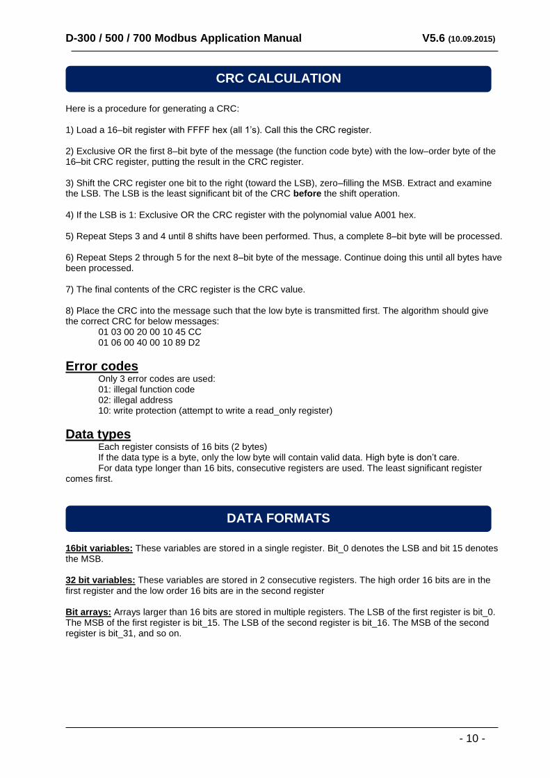
Here is a procedure for generating a CRC: 1) Load a 16–bit register with FFFF hex (all 1’s). Call this the CRC register. 2) Exclusive OR the first 8–bit byte of the message (the function code byte) with the low–order byte of the 16–bit CRC register, putting the result in the CRC register. 3) Shift the CRC register one bit to the right (toward the LSB), zero–filling the MSB. Extract and examine the LSB. The LSB is the least significant bit of the CRC before the shift operation. 4) If the LSB is 1: Exclusive OR the CRC register with the polynomial value A001 hex. 5) Repeat Steps 3 and 4 until 8 shifts have been performed. Thus, a complete 8–bit byte will be processed. 6) Repeat Steps 2 through 5 for the next 8–bit byte of the message. Continue doing this until all bytes have been processed. 7) The final contents of the CRC register is the CRC value. 8) Place the CRC into the message such that the low byte is transmitted first. The algorithm should give the correct CRC for below messages: 01 03 00 20 00 10 45 CC 01 06 00 40 00 10 89 D2
Error codes Only 3 error codes are used: 01: illegal function code 02: illegal address 10: write protection (attempt to write a read_only register)
Data types Each register consists of 16 bits (2 bytes) If the data type is a byte, only the low byte will contain valid data. High byte is don’t care. For data type longer than 16 bits, consecutive registers are used. The least significant register comes first.
16bit variables: These variables are stored in a single register. Bit_0 denotes the LSB and bit 15 denotes the MSB. 32 bit variables: These variables are stored in 2 consecutive registers. The high order 16 bits are in the first register and the low order 16 bits are in the second register Bit arrays: Arrays larger than 16 bits are stored in multiple registers. The LSB of the first register is bit_0. The MSB of the first register is bit_15. The LSB of the second register is bit_16. The MSB of the second register is bit_31, and so on.
DATA FORMATS
CRC CALCULATION
D-300 / 500 / 700 Modbus Application Manual V5.6 (10.09.2015)
- 11 -
ADDRESS (decimal)
R / W DATA SIZE
COEFF. DESCRIPTION
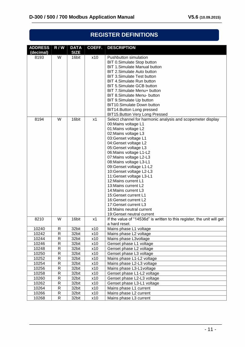
8193 W 16bit x10 Pushbutton simulation BIT 0.Simulate Stop button BIT 1.Simulate Manual button BIT 2.Simulate Auto button BIT 3.Simulate Test button BIT 4.Simulate Run button BIT 5.Simulate GCB button BIT 7.Simulate Menu+ button BIT 8.Simulate Menu- button BIT 9.Simulate Up button BIT10.Simulate Down button BIT14.Button Long pressed BIT15.Button Very Long Pressed
8194 W 16bit x1 Select channel for harmonic analysis and scopemeter display 00:Mains voltage L1 01:Mains voltage L2 02:Mains voltage L3 03:Genset voltage L1 04:Genset voltage L2 05:Genset voltage L3 06:Mains voltage L1-L2 07:Mains voltage L2-L3 08:Mains voltage L3-L1 09:Genset voltage L1-L2 10:Genset voltage L2-L3 11:Genset voltage L3-L1 12:Mains current L1 13:Mains current L2 14:Mains current L3 15:Genset current L1 16:Genset current L2 17:Genset current L3 18:Mains neutral current 19:Genset neutral current
8210 W 16bit x1 If the value of “14536d” is written to this register, the unit will get a hard reset.
10240 R 32bit x10 Mains phase L1 voltage
10242 R 32bit x10 Mains phase L2 voltage
10244 R 32bit x10 Mains phase L3voltage
10246 R 32bit x10 Genset phase L1 voltage
10248 R 32bit x10 Genset phase L2 voltage
10250 R 32bit x10 Genset phase L3 voltage
10252 R 32bit x10 Mains phase L1-L2 voltage
10254 R 32bit x10 Mains phase L2-L3 voltage
10256 R 32bit x10 Mains phase L3-L1voltage
10258 R 32bit x10 Genset phase L1-L2 voltage
10260 R 32bit x10 Genset phase L2-L3 voltage
10262 R 32bit x10 Genset phase L3-L1 voltage
10264 R 32bit x10 Mains phase L1 current
10266 R 32bit x10 Mains phase L2 current
10268 R 32bit x10 Mains phase L3 current
REGISTER DEFINITIONS
D-300 / 500 / 700 Modbus Application Manual V5.6 (10.09.2015)
- 12 -
ADDRESS (decimal)
R / W DATA SIZE
COEFF. DESCRIPTION
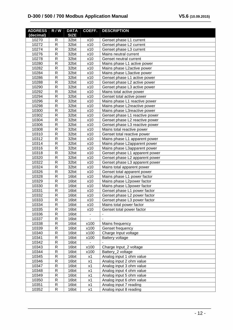
10270 R 32bit x10 Genset phase L1 current
10272 R 32bit x10 Genset phase L2 current
10274 R 32bit x10 Genset phase L3 current
10276 R 32bit x10 Mains neutral current
10278 R 32bit x10 Genset neutral current
10280 R 32bit x10 Mains phase L1 active power
10282 R 32bit x10 Mains phase L2active power
10284 R 32bit x10 Mains phase L3active power
10286 R 32bit x10 Genset phase L1 active power
10288 R 32bit x10 Genset phase L2 active power
10290 R 32bit x10 Genset phase L3 active power
10292 R 32bit x10 Mains total active power
10294 R 32bit x10 Genset total active power
10296 R 32bit x10 Mains phase L1 reactive power
10298 R 32bit x10 Mains phase L2reactive power
10300 R 32bit x10 Mains phase L3reactive power
10302 R 32bit x10 Genset phase L1 reactive power
10304 R 32bit x10 Genset phase L2 reactive power
10306 R 32bit x10 Genset phase L3 reactive power
10308 R 32bit x10 Mains total reactive power
10310 R 32bit x10 Genset total reactive power
10312 R 32bit x10 Mains phase L1 apparent power
10314 R 32bit x10 Mains phase L2apparent power
10316 R 32bit x10 Mains phase L3apparent power
10318 R 32bit x10 Genset phase L1 apparent power
10320 R 32bit x10 Genset phase L2 apparent power
10322 R 32bit x10 Genset phase L3 apparent power
10324 R 32bit x10 Mains total apparent power
10326 R 32bit x10 Genset total apparent power
10328 R 16bit x10 Mains phase L1 power factor
10329 R 16bit x10 Mains phase L2power factor
10330 R 16bit x10 Mains phase L3power factor
10331 R 16bit x10 Genset phase L1 power factor
10332 R 16bit x10 Genset phase L2 power factor
10333 R 16bit x10 Genset phase L3 power factor
10334 R 16bit x10 Mains total power factor
10335 R 16bit x10 Genset total power factor
10336 R 16bit - -
10337 R 16bit - -
10338 R 16bit x100 Mains frequency
10339 R 16bit x100 Genset frequency
10340 R 16bit x100 Charge Input voltage
10341 R 16bit x100 Battery voltage
10342 R 16bit - -
10343 R 16bit x100 Charge Input_2 voltage
10344 R 16bit x100 Battery_2 voltage
10345 R 16bit x1 Analog input 1 ohm value
10346 R 16bit x1 Analog input 2 ohm value
10347 R 16bit x1 Analog input 3 ohm value
10348 R 16bit x1 Analog input 4 ohm value
10349 R 16bit x1 Analog input 5 ohm value
10350 R 16bit x1 Analog input 6 ohm value
10351 R 16bit x1 Analog input 7 reading
10352 R 16bit x1 Analog input 8 reading
D-300 / 500 / 700 Modbus Application Manual V5.6 (10.09.2015)
- 13 -
ADDRESS (decimal)
R / W DATA SIZE
COEFF. DESCRIPTION
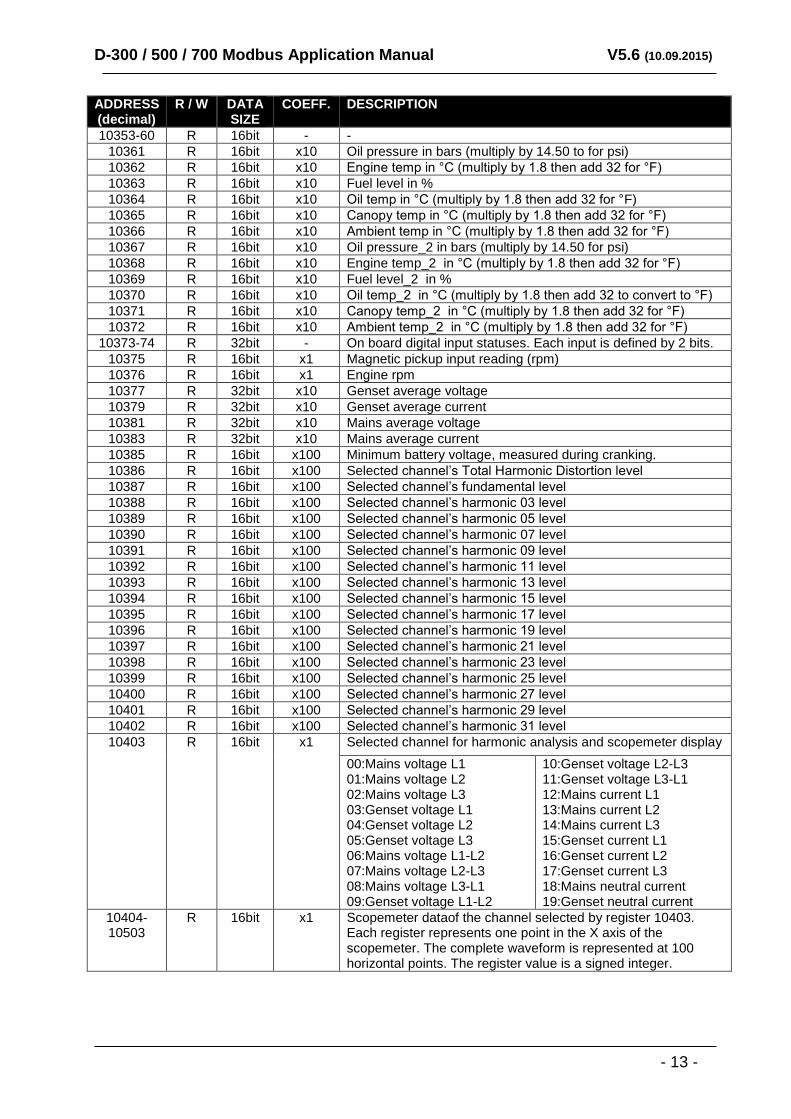
10353-60 R 16bit - -
10361 R 16bit x10 Oil pressure in bars (multiply by 14.50 to for psi)
10362 R 16bit x10 Engine temp in °C (multiply by 1.8 then add 32 for °F)
10363 R 16bit x10 Fuel level in %
10364 R 16bit x10 Oil temp in °C (multiply by 1.8 then add 32 for °F)
10365 R 16bit x10 Canopy temp in °C (multiply by 1.8 then add 32 for °F)
10366 R 16bit x10 Ambient temp in °C (multiply by 1.8 then add 32 for °F)
10367 R 16bit x10 Oil pressure_2 in bars (multiply by 14.50 for psi)
10368 R 16bit x10 Engine temp_2 in °C (multiply by 1.8 then add 32 for °F)
10369 R 16bit x10 Fuel level_2 in %
10370 R 16bit x10 Oil temp_2 in °C (multiply by 1.8 then add 32 to convert to °F)
10371 R 16bit x10 Canopy temp_2 in °C (multiply by 1.8 then add 32 for °F)
10372 R 16bit x10 Ambient temp_2 in °C (multiply by 1.8 then add 32 for °F)
10373-74 R 32bit - On board digital input statuses. Each input is defined by 2 bits.
10375 R 16bit x1 Magnetic pickup input reading (rpm)
10376 R 16bit x1 Engine rpm
10377 R 32bit x10 Genset average voltage
10379 R 32bit x10 Genset average current
10381 R 32bit x10 Mains average voltage
10383 R 32bit x10 Mains average current
10385 R 16bit x100 Minimum battery voltage, measured during cranking.
10386 R 16bit x100 Selected channel’s Total Harmonic Distortion level
10387 R 16bit x100 Selected channel’s fundamental level
10388 R 16bit x100 Selected channel’s harmonic 03 level
10389 R 16bit x100 Selected channel’s harmonic 05 level
10390 R 16bit x100 Selected channel’s harmonic 07 level
10391 R 16bit x100 Selected channel’s harmonic 09 level
10392 R 16bit x100 Selected channel’s harmonic 11 level
10393 R 16bit x100 Selected channel’s harmonic 13 level
10394 R 16bit x100 Selected channel’s harmonic 15 level
10395 R 16bit x100 Selected channel’s harmonic 17 level
10396 R 16bit x100 Selected channel’s harmonic 19 level
10397 R 16bit x100 Selected channel’s harmonic 21 level
10398 R 16bit x100 Selected channel’s harmonic 23 level
10399 R 16bit x100 Selected channel’s harmonic 25 level
10400 R 16bit x100 Selected channel’s harmonic 27 level
10401 R 16bit x100 Selected channel’s harmonic 29 level
10402 R 16bit x100 Selected channel’s harmonic 31 level
10403 R 16bit x1 Selected channel for harmonic analysis and scopemeter display
00:Mains voltage L1 01:Mains voltage L2 02:Mains voltage L3 03:Genset voltage L1 04:Genset voltage L2 05:Genset voltage L3 06:Mains voltage L1-L2 07:Mains voltage L2-L3 08:Mains voltage L3-L1 09:Genset voltage L1-L2
10:Genset voltage L2-L3 11:Genset voltage L3-L1 12:Mains current L1 13:Mains current L2 14:Mains current L3 15:Genset current L1 16:Genset current L2 17:Genset current L3 18:Mains neutral current 19:Genset neutral current
10404- 10503
R 16bit x1 Scopemeter dataof the channel selected by register 10403. Each register represents one point in the X axis of the scopemeter. The complete waveform is represented at 100 horizontal points. The register value is a signed integer.
D-300 / 500 / 700 Modbus Application Manual V5.6 (10.09.2015)
- 14 -
ADDRESS (decimal)
R / W DATA SIZE
COEFF. DESCRIPTION
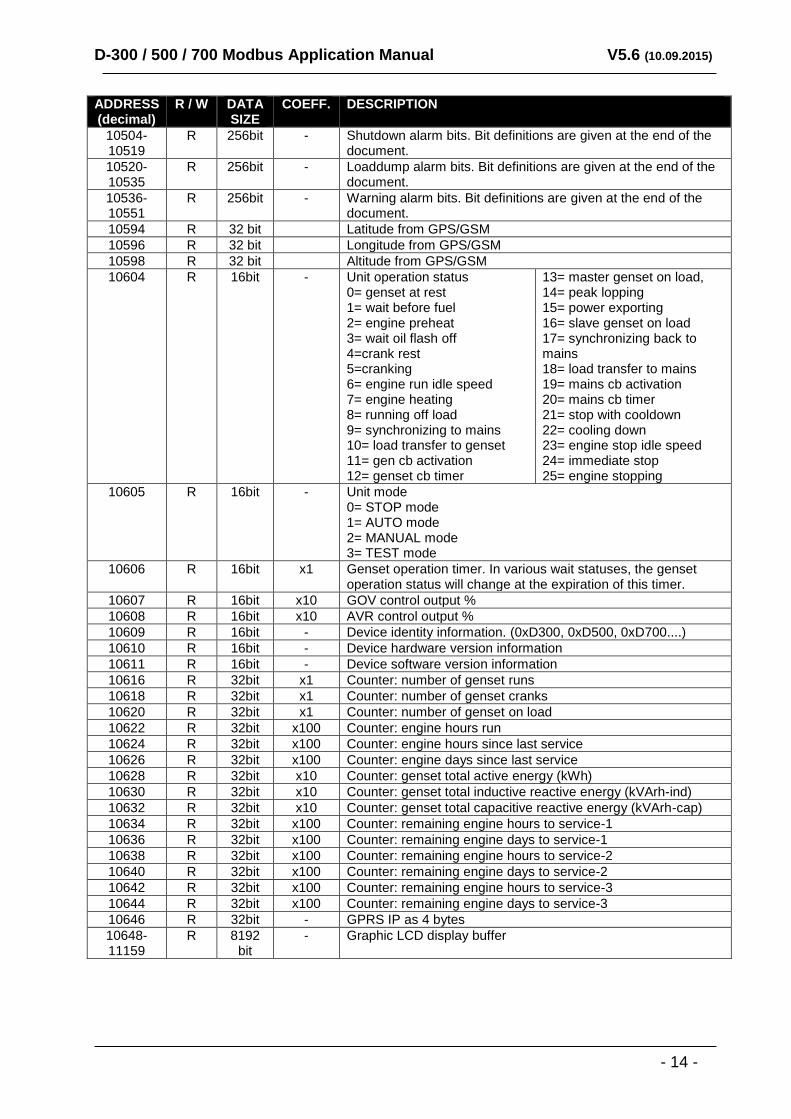
10504-10519
R 256bit - Shutdown alarm bits. Bit definitions are given at the end of the document.
10520-10535
R 256bit - Loaddump alarm bits. Bit definitions are given at the end of the document.
10536-10551
R 256bit - Warning alarm bits. Bit definitions are given at the end of the document.
10594 R 32 bit Latitude from GPS/GSM
10596 R 32 bit Longitude from GPS/GSM
10598 R 32 bit Altitude from GPS/GSM
10604 R 16bit - Unit operation status 0= genset at rest 1= wait before fuel 2= engine preheat 3= wait oil flash off 4=crank rest 5=cranking 6= engine run idle speed 7= engine heating 8= running off load 9= synchronizing to mains 10= load transfer to genset 11= gen cb activation 12= genset cb timer
13= master genset on load, 14= peak lopping 15= power exporting 16= slave genset on load 17= synchronizing back to mains 18= load transfer to mains 19= mains cb activation 20= mains cb timer 21= stop with cooldown 22= cooling down 23= engine stop idle speed 24= immediate stop 25= engine stopping
10605 R 16bit - Unit mode 0= STOP mode 1= AUTO mode 2= MANUAL mode 3= TEST mode
10606 R 16bit x1 Genset operation timer. In various wait statuses, the genset operation status will change at the expiration of this timer.
10607 R 16bit x10 GOV control output %
10608 R 16bit x10 AVR control output %
10609 R 16bit - Device identity information. (0xD300, 0xD500, 0xD700....)
10610 R 16bit - Device hardware version information
10611 R 16bit - Device software version information
10616 R 32bit x1 Counter: number of genset runs
10618 R 32bit x1 Counter: number of genset cranks
10620 R 32bit x1 Counter: number of genset on load
10622 R 32bit x100 Counter: engine hours run
10624 R 32bit x100 Counter: engine hours since last service
10626 R 32bit x100 Counter: engine days since last service
10628 R 32bit x10 Counter: genset total active energy (kWh)
10630 R 32bit x10 Counter: genset total inductive reactive energy (kVArh-ind)
10632 R 32bit x10 Counter: genset total capacitive reactive energy (kVArh-cap)
10634 R 32bit x100 Counter: remaining engine hours to service-1
10636 R 32bit x100 Counter: remaining engine days to service-1
10638 R 32bit x100 Counter: remaining engine hours to service-2
10640 R 32bit x100 Counter: remaining engine days to service-2
10642 R 32bit x100 Counter: remaining engine hours to service-3
10644 R 32bit x100 Counter: remaining engine days to service-3
10646 R 32bit - GPRS IP as 4 bytes
10648-11159
R 8192 bit
- Graphic LCD display buffer
D-300 / 500 / 700 Modbus Application Manual V5.6 (10.09.2015)
- 15 -
ADDRESS (decimal)
R / W DATA SIZE
COEFF. DESCRIPTION
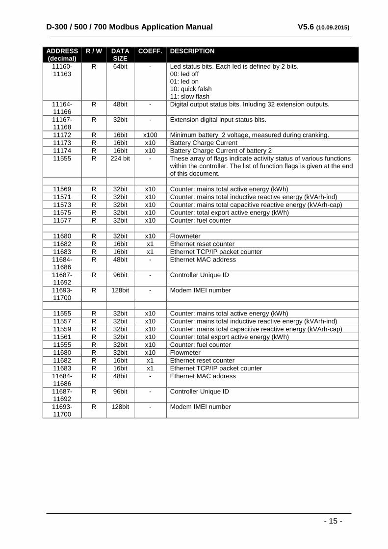
11160-11163
R 64bit - Led status bits. Each led is defined by 2 bits. 00: led off 01: led on 10: quick falsh 11: slow flash
11164-11166
R 48bit - Digital output status bits. Inluding 32 extension outputs.
11167-11168
R 32bit - Extension digital input status bits.
11172 R 16bit x100 Minimum battery_2 voltage, measured during cranking.
11173 R 16bit x10 Battery Charge Current
11174 R 16bit x10 Battery Charge Current of battery 2
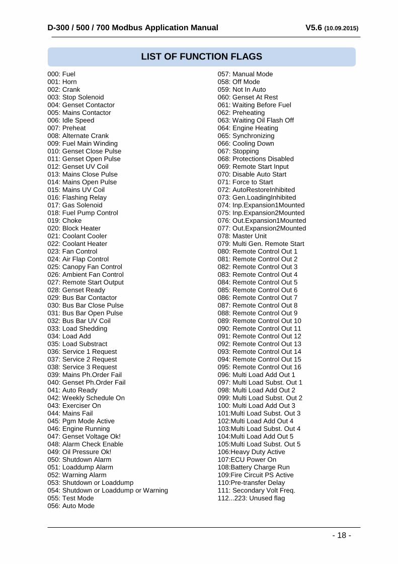
11555 R 224 bit - These array of flags indicate activity status of various functions within the controller. The list of function flags is given at the end of this document.
11569 R 32bit x10 Counter: mains total active energy (kWh)
11571 R 32bit x10 Counter: mains total inductive reactive energy (kVArh-ind)
11573 R 32bit x10 Counter: mains total capacitive reactive energy (kVArh-cap)
11575 R 32bit x10 Counter: total export active energy (kWh)
11577 R 32bit x10 Counter: fuel counter
11680 R 32bit x10 Flowmeter
11682 R 16bit x1 Ethernet reset counter
11683 R 16bit x1 Ethernet TCP/IP packet counter
11684-11686
R 48bit - Ethernet MAC address
11687-11692
R 96bit - Controller Unique ID
11693-11700
R 128bit - Modem IMEI number
11555 R 32bit x10 Counter: mains total active energy (kWh)
11557 R 32bit x10 Counter: mains total inductive reactive energy (kVArh-ind)
11559 R 32bit x10 Counter: mains total capacitive reactive energy (kVArh-cap)
11561 R 32bit x10 Counter: total export active energy (kWh)
11555 R 32bit x10 Counter: fuel counter
11680 R 32bit x10 Flowmeter
11682 R 16bit x1 Ethernet reset counter
11683 R 16bit x1 Ethernet TCP/IP packet counter
11684-11686
R 48bit - Ethernet MAC address
11687-11692
R 96bit - Controller Unique ID
11693-11700
R 128bit - Modem IMEI number
D-300 / 500 / 700 Modbus Application Manual V5.6 (10.09.2015)
- 16 -
ADDRESS (decimal)
R / W DATA SIZE
COEFF. DESCRIPTION
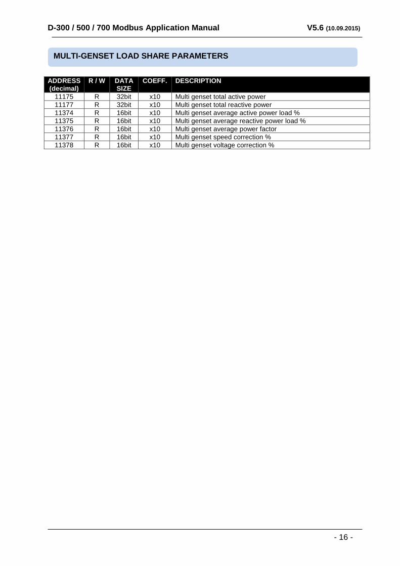
11175 R 32bit x10 Multi genset total active power
11177 R 32bit x10 Multi genset total reactive power
11374 R 16bit x10 Multi genset average active power load %
11375 R 16bit x10 Multi genset average reactive power load %
11376 R 16bit x10 Multi genset average power factor
11377 R 16bit x10 Multi genset speed correction %
11378 R 16bit x10 Multi genset voltage correction %
MULTI-GENSET LOAD SHARE PARAMETERS
D-300 / 500 / 700 Modbus Application Manual V5.6 (10.09.2015)
- 17 -
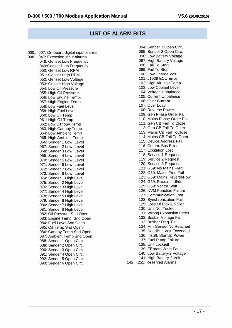
000....007: On-board digital input alarms 008....047: Extension input alarms 048: Genset Low Frequency 049:Genset High Frequency 050: Genset Low RPM 051: Genset High RPM 052: Genset Low Voltage 053: Genset High Voltage 054: Low Oil Pressure 055: High Oil Pressure 056: Low Engine Temp. 057: High Engine Temp. 058: Low Fuel Level 059: High Fuel Level 060: Low Oil Temp 061: High Oil Temp 062: Low Canopy Temp 063: High Canopy Temp 064: Low Ambient Temp 065: High Ambient Temp 066: Sender 1 Low Level 067: Sender 2 Low Level 068: Sender 3 Low Level 069: Sender 4 Low Level 070: Sender 5 Low Level 071: Sender 6 Low Level 072: Sender 7 Low Level 073: Sender 8 Low Level 074: Sender 1 High Level 075: Sender 2 High Level 076: Sender 3 High Level 077: Sender 4 High Level 078: Sender 5 High Level 079: Sender 6 High Level 080: Sender 7 High Level 081: Sender 8 High Level 082: Oil Pressure Snd Open 083: Engine Temp. Snd Open 084: Fuel Level Snd Open 085: Oil Temp Snd Open 086: Canopy Temp Snd Open 087: Ambient Temp Snd Open 088: Sender 1 Open Circ. 089: Sender 2 Open Circ. 090: Sender 3 Open Circ. 091: Sender 4 Open Circ. 092: Sender 5 Open Circ. 093: Sender 6 Open Circ.
094: Sender 7 Open Circ. 095: Sender 8 Open Circ. 096: Low Battery Voltage 097: High Battery Voltage 098: Fail To Start 099: Fail To Stop 100: Low Charge Volt 101: J1939 ECU Error 102: High Air Inlet Temp 103: Low Coolant Level 104: Voltage Unbalance 105: Current Unbalance 106: Over Current 107: Over Load 108: Reverse Power 109: Gen Phase Order Fail 110: Mains Phase Order Fail 111: Gen CB Fail To Close 112: Gen CB Fail To Open 113: Mains CB Fail ToClose 114: Mains CB Fail To Open 115: Device Address Fail 116: Comm. Bus Error 117: Excitation Lost 118: Service 1 Request 119: Service 2 Request 120: Service 3 Request 121: G59: No Mains Freq. 122: G59: Mains Freq Fail 123: G59: Mains ReversePow 124: G59: R.o.c.o.f. df/dt 125: G59: Vector Shift 126: NVM Function Failure 127: Communication Lost 128: Synchronization Fail 129: Loss Of Pick-Up Sign 130: Unit Not Tested! 131: Wrong Expansion Order 132: Busbar Voltage Fail 133: Busbar Freq. Fail 134: Min Genset NotReached 135: DeadBus Volt Exceeded 136: Insuff. StartUp Power 137: Fuel Pump Failure 138: Unit Locked! 139: EEprom Write Fault 140: Low Battery-2 Voltage 141: High Battery-2 Volt. 142....255: Reserved Alarms
LIST OF ALARM BITS
D-300 / 500 / 700 Modbus Application Manual V5.6 (10.09.2015)
- 18 -
000: Fuel 001: Horn 002: Crank 003: Stop Solenoid 004: Genset Contactor 005: Mains Contactor 006: Idle Speed 007: Preheat 008: Alternate Crank 009: Fuel Main Winding 010: Genset Close Pulse 011: Genset Open Pulse 012: Genset UV Coil 013: Mains Close Pulse 014: Mains Open Pulse 015: Mains UV Coil 016: Flashing Relay 017: Gas Solenoid 018: Fuel Pump Control 019: Choke 020: Block Heater 021: Coolant Cooler 022: Coolant Heater 023: Fan Control 024: Air Flap Control 025: Canopy Fan Control 026: Ambient Fan Control 027: Remote Start Output 028: Genset Ready 029: Bus Bar Contactor 030: Bus Bar Close Pulse 031: Bus Bar Open Pulse 032: Bus Bar UV Coil 033: Load Shedding 034: Load Add 035: Load Substract 036: Service 1 Request 037: Service 2 Request 038: Service 3 Request 039: Mains Ph.Order Fail 040: Genset Ph.Order Fail 041: Auto Ready 042: Weekly Schedule On 043: Exerciser On 044: Mains Fail 045: Pgm Mode Active 046: Engine Running 047: Genset Voltage Ok! 048: Alarm Check Enable 049: Oil Pressure Ok! 050: Shutdown Alarm 051: Loaddump Alarm 052: Warning Alarm 053: Shutdown or Loaddump 054: Shutdown or Loaddump or Warning 055: Test Mode 056: Auto Mode
057: Manual Mode 058: Off Mode 059: Not In Auto 060: Genset At Rest 061: Waiting Before Fuel 062: Preheating 063: Waiting Oil Flash Off 064: Engine Heating 065: Synchronizing 066: Cooling Down 067: Stopping 068: Protections Disabled 069: Remote Start Input 070: Disable Auto Start 071: Force to Start 072: AutoRestoreInhibited 073: Gen.LoadingInhibited 074: Inp.Expansion1Mounted 075: Inp.Expansion2Mounted 076: Out.Expansion1Mounted 077: Out.Expansion2Mounted 078: Master Unit 079: Multi Gen. Remote Start 080: Remote Control Out 1 081: Remote Control Out 2 082: Remote Control Out 3 083: Remote Control Out 4 084: Remote Control Out 5 085: Remote Control Out 6 086: Remote Control Out 7 087: Remote Control Out 8 088: Remote Control Out 9 089: Remote Control Out 10 090: Remote Control Out 11 091: Remote Control Out 12 092: Remote Control Out 13 093: Remote Control Out 14 094: Remote Control Out 15 095: Remote Control Out 16 096: Multi Load Add Out 1 097: Multi Load Subst. Out 1 098: Multi Load Add Out 2 099: Multi Load Subst. Out 2 100: Multi Load Add Out 3 101:Multi Load Subst. Out 3 102:Multi Load Add Out 4 103:Multi Load Subst. Out 4 104:Multi Load Add Out 5 105:Multi Load Subst. Out 5 106:Heavy Duty Active 107:ECU Power On 108:Battery Charge Run 109:Fire Circuit PS Active 110:Pre-transfer Delay 111: Secondary Volt Freq. 112...223: Unused flag
LIST OF FUNCTION FLAGS