czm grant app - michigan technological universitypages.mtu.edu/~asmayer/huroncreek/appendix/app...
TRANSCRIPT

Bank Stabilization and Improvement of Huron Creek in the Kestner Waterfront Park Houghton, Michigan
Park Description The Kestner Waterfront Park is located within the city limits of Houghton, Michigan along Portage Lake. Due to its scenic location and ample facilities, the park is one of the most popular in the city. Facilities include a swimming beach, launch site for kayaks and sailboats, an extensive playground area, picnic tables, grills and a lakeside walking path. An RV park is located immediately to the west, and boat docking and launching facilities are located immediately to the east of the park proper. The park also has a pavilion and band shell, making it a prime location for many outdoor events and gatherings. A photo of the north side of the park is provided as Figure 1 below.
Figure 1 – Kestner Waterfront Park Figure 2 – Huron Creek in Park, September 2007
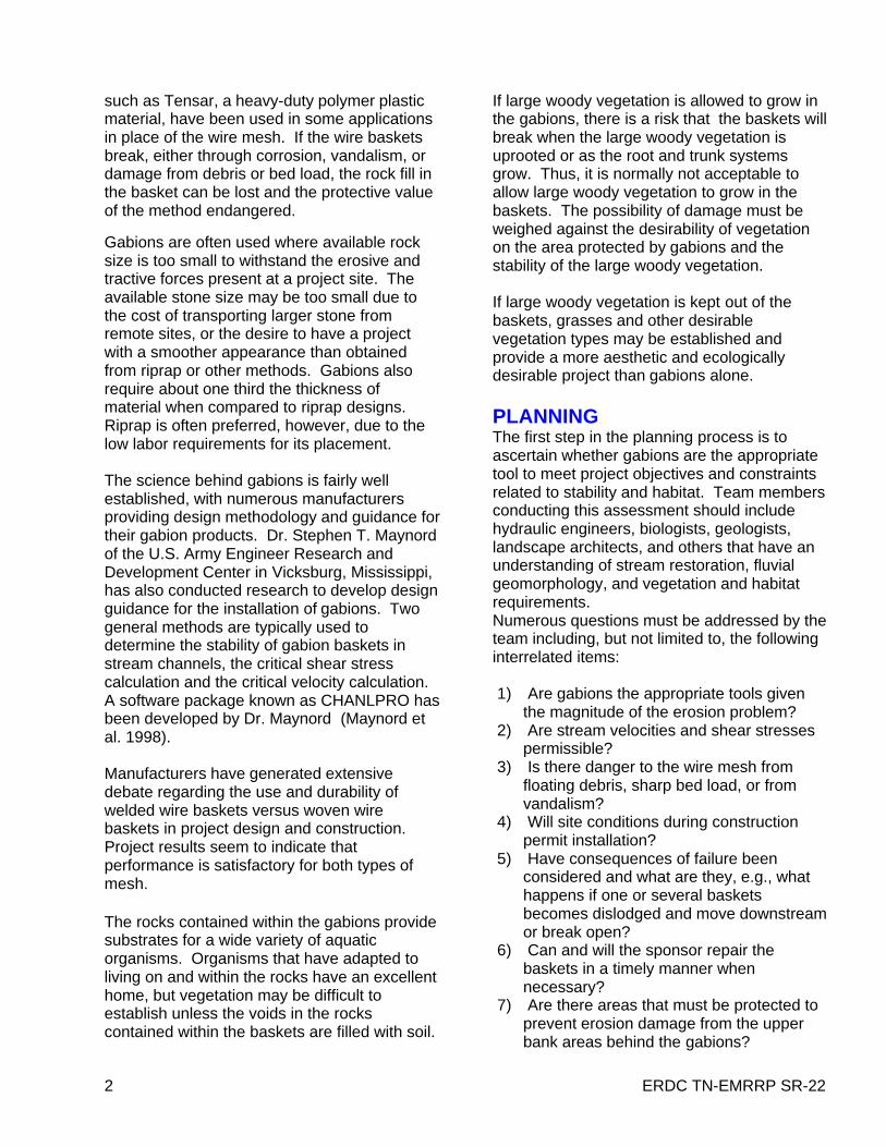
Purpose of the Project The primary goal of this project is to improve the channel of Huron Creek in Kestner Waterfront Park to provide slope stability and more attractive, naturalized streambanks. Huron Creek travels through the Kestner waterfront park for approximately 350 feet before flowing into the Portage waterway beneath a concrete walkway. Historically there have been repeated problems with the banks of Huron Creek washing out from erosion during storms. A severe storm in September 2007 caused several bank areas to completely fail (Figure 2) resulting in steep, undercut and unprotected slopes. Various methods have been used to attempt to stabilize the banks over the years including rip‐rap, herbaceous plantings and erosion matting with lawn grass. Each method has eventually given way to bank erosion.
In an attempt to repair the banks and ideally stabilize them permanently, the City of Houghton is proposing to implement biotechnical stabilization along the bank areas in the park as shown in the attached Figure 3. The stabilization will consist of three components: (a) installation of rock‐filled gabions at the toe of the bank slopes to protect against erosion during high flow events; (b) re‐grading the bank slopes to grades of between 3H:1V and 2H:1V; and (c) planting the slopes and gabions with native trees, shrubs and grasses.
Essential Elements of Project The following items describe the biotechnical stabilization method proposed by the City of Houghton:
1. Excavate slopes back to a shallower angle; 3H:1V where possible, otherwise 2H:1V given a buffer strip width of 12 to 18 feet.
2. Install two levels of stone‐filled gabions at the toe of the slope. The bottom gabion is to be sunk into the creek bed to provide protection against undercutting. Both the top and bottom gabions are to be installed at an angle to provide against the potential for sliding. A typical cross‐section of an improved slope is provided as Figure 4.
3. Plant native shrubs into bank on top of upper gabion to provide additional toe and bank stabilization. This measure, along with
the lower gabion being sunk into the creek bed will help cover the gabions to add a more natural look to the creek while sufficiently stabilizing it. Figure 5 shows typical native shrub placement on top of the gabions.
4. Plant a mixture of native grasses, shrubs and trees within a 12 to 18‐foot buffer strip along biotechnical stabilization areas. This
will contribute to bank stabilization, help cover and prevent access to the gabions, and help create a more natural creek corridor. Planting locations and details are provided on Figures 6 and 7. Native plant species are included in drawing notes and an attachment.

The City of Houghton acknowledges that the Michigan Coastal Management Program generally does not support the use of “hard” shore protection such as gabions. However, after several tries at stabilization, and discussions with local experts such as Natural Resource Conservation Service (NRCS) representatives, it is our conclusion that hard stabilization at the toe of the banks is necessary for long‐term success. Velocities of Huron Creek in the Kestner Waterfront Park can exceed those allowed as maximum for “soft” measures such as coir logs or lone vegetative stabilization. These high velocities can be attributed to steep topographies (surface slopes exceed 10%‐15% in some locations) and a significant amount of urban development upstream.
Relationship to Larger Projects This proposed project is also being completed in support of the Huron Creek Watershed Management Plan (MDEQ grant tracking #2006‐0162) which is being funded by the Michigan Department of Environmental Quality. The Michigan Technological University (MTU) Center for Water and Society (CWS) is responsible for developing the watershed management plan. A watershed advisory committee (WAC) was formed in 2006 as part of the watershed management planning efforts. Since the Kestner Waterfront Park provides one of the few places in the watershed where visitors can “interact” with the creek, it is a goal of the Huron Creek WAC that this location be utilized to spread awareness of the creek and watershed management. The Huron Creek WAC has recommended that improving the banks of the creek would provide a healthy, visually appealing creek would and encourage support to protect and restore the remainder of the Creek. An interpretive sign describing the Huron Creek watershed and watershed health was installed in the park adjacent to the creek in 2007.
The MTU CWS has provided designs, calculations, cost estimates and drawings for submittal with this proposal as well as for inclusion in the watershed management plan.
Improvements to Huron Creek in the Kestner Waterfront Park have been suggested in the City of Houghton’s “Recreation Plan 2008– 2013” (see http://www.cityofhoughton.com/news/45.pdf).
Relationship to Existing Facilities In the Kestner Waterfront Park, Huron Creek is located centrally between a popular swimming area and another small beach and boat launching area. After some storm events, eroded sediment and debris can be seen along the banks and discharging from the mouth of the creek into Portage Lake towards these areas. This can create visually displeasing conditions at these locations, as well as negatively affect the water quality.
Project Budget Gabion materials and installation $48,000
Bank grading $15,000
Grass, shrubs, trees, fertilizer and installation $12,500
Erosion mat, stakes and installation $6,500
TOTAL $82,000
Funding Source Local match for this project includes funds appropriated by the City of Houghton for the city recreation plan and in‐kind labor.

A: 120 ft –Fi 3
outlet
NStabilize
B: 130 ft –Stabilize
Figure 3:
Plan Viewall dimensions are approximate
C: 30 ft - Stabilize
D: 50 ft - Open
approximate
scale: approx.60 ft /in
parking
E: 80 ft - Open
G: 50 ft - Stabilize
pa glot
sidewalks
F: 50 ft - Stabilize
I: 55 ft - Stabilizesidewalks
campground
H: 50 ft -Stabilize
campground road

Fi 4Staked erosion bl k t t
set second
Figure 4:
Typical Bank Cross-Section plant slopes with native
grass, shrubs and trees
blanket to cover newly graded surface
> 2:1cut slopes back to 3H:1V if possible
gabion back ~ 9 in
all dimensions are approximate
(otherwise 2H:1V)
finish slope to outward end of gabionsbed
creek
~ 5 ft
Two (2) ~3 ft x 3 ft x 6 ft (H x W x L) galvanized gabions, rotated minimum of 6°. Fill with 4 to 8 in stone.
excavate gabion ~ 2 ft 6 . Fill with 4 to 8 in stone.gabion ~ 2 ft below bed
filter cloth placed under, on top of and behind gabions

Figure 5:
Examples of Shrub Placement in or on Gabions
slope
Shrubs to be planted 2 per stack of 6-foot long gabions
creek
slope(see detail)
bed
Shrub Planting Detail (view from creek or bank)
2’ 2’ 2’ Ball-stock shrubs (w/ root ball included)
http://www.epa.gov/owow/nps/unpavedroads/ch5.pdf
Gabions

Figure 6: Vegetation Detailsrefer to Figures 3 and 8 for location
Typical Vegetative Buffer – “Stabilize” Typical Vegetative Buffer –
All dimensions are approximate. Shrub and tree placement shown is not exact - for figurative purposes only.Shrubs can be live stakes or balled stock (root ball included). See notes for more planting information.
yp g
12-18 ft
“Open” Erosion mat over entire buffer
Erosion mat over entire buffer
NO gabionsPlant native
grasses and
shrub density: ~ 1 shrub per 3-5 sq. ft
forbs only
Native grasses and forbs intermixed among shrubs and trees (hatching not sho n)
trees
shrubs
grasses shown)
scale: approx. 25 ft /in
gabions & forbs

A
Fi 7
outlet
B
Figure 7:
Plan View with Improvements
C see Figures 6 and 7 for details on sections A, B, C, D, and E
scale: approx.60 ft /inparking
C
DE
pa glot
sidewalksF
G trees
shrubsIsidewalks
campground
shrubs
H
I
campground road

NOTES:1. Bank planting & grading areas should be kept to a maximum12-foot width near sidewalks
(Areas E and F).
2. Bank slopes shall be graded to 3H:1V where possible, otherwise 2H:1V.
3. If sediments from the creek bed are mechanically removed as part of regular park maintenance ensure that 2 feet of bed cover remains next to the bottom of the gabions tomaintenance, ensure that 2 feet of bed cover remains next to the bottom of the gabions to keep them in place.
4. GABIONS: Nearest supplier of Macaferri gabions is CSI Geoturf – Contact: David Ringle. Phone: (231)943-4002 ( )657 W. Blue Star Drive, Traverse City, Michigan 49684
Technical support and CAD drawings (sometimes for free for public projects):Macaferri GabionsKen Hughes/Tersea Lynch 2351 Versailles Rd., Ste. 302 Lexington, KY 40504 E M il k ffi @ f i T l h 859 255 1343E-Mail: [email protected] Telephone: 859.255.1343
See attached Macaferri specification sheet for gabions sizing and installation information.
5. See attached U.S. Army Corps of Engineers document SR-22, Gabions for StreambankErosion Control for installation recommendationsErosion Control for installation recommendations.
6. Cost provided for gabions is for galvanized gabions only (not PVC-coated). Cost includes shipping and enough wire for gabion assembly. Can also purchase “hog rings” for connection that can be easier to use/install- additional cost for 90 gabions ~ $700.00.
7. GRASSES: a) A suggested mesic (tolerant to dry and wet conditions) seed mix is attached. This
seed mix has been provided by Borealis Seed Co., Marquette, MI. (906) 226-8507. b) Suggested application rate = 1 lb/3,000 sq.ft. Plant throughout vegetated area.

NOTES (continued):8. SHRUBS:
a) Suggested species of shrubs:a) Suggested species of shrubs:• red-osier dogwood (Cornus stolonifera)• ninebark (Physocarpus opulifolius) • upland willow (Salix humilis)• pussy willow (Salix discolor)
b) *Shrubs planted on top of gabions should be balled stock for best establishment. Shrubsb) Shrubs planted on top of gabions should be balled stock for best establishment. Shrubs planted on bank can be balled stock or live stakes. Live stakes are less expensive, but balled stock establishes more quickly. Also live stakes look, initially less visually appealing.
9. TREES:a) Suggested species of trees:
• red maple (Acer rubrum)• quaking aspen (Populus tremuloides)• white or paper birch (Betula papyrifera)
10. EROSION BLANKET & STAKES:a) Curlex HV (High Velocity) Straw/Coconut mat or similar is recommended www curlex coma) Curlex HV (High Velocity) Straw/Coconut mat or similar is recommended. www.curlex.com. b) 6” wire stakes are recommended for fastening to bank. See manufacturer instructions for
proper installation.c) Erosion blanket to be installed and secured after seeding and fertilization.
11. Suppliers of Trees, Shrubs and Erosion Mat:pp ,a) Lake Superior Tree Farm, Chassell,MI, 906-523-6200 (Contact: David Crouch)b) Great Lakes Nursery, Watervliet, MI, 269-468-3323, www.greatlakesnurseryco.com/c) Cold Stream Nursery, Free Soil, MI, 231-464-5809, www.coldstreamfarm.net/d) Engels Nursery, Fennville, MI, 296-543-4123, www.engelsnursery.com/e) *Follow vegetation supplier instructions for planting, fertilization and care.
10. Fertilizer should be applied to bank area when planting vegetation. 3/10/10 fertilizer is recommended. Slow-release fertilizers are not recommended. Follow manufacturer application instructions closely.

ERDC TN-EMRRP SR-22 1
Low Moderate High
Complexity
Low Moderate High
Environmental Value
Low Moderate High
Cost
Gabions for StreambankErosion Control
by Gary E. Freeman1 and J. Craig Fischenich2 May 2000
1 River Research and Design, Inc., 1092 N. 75 E., Orem, UT 840572 USAE Waterways Experiment Station, 3909 Halls Ferry Rd., Vicksburg, MS 39180
OVERVIEWGabions are cylinders that are filled with earthor stones, which are used in building structuressuch as dams or dikes. Gabions have beenused for several millennia in Egypt and China.Prior to 1879, gabions were constructed withplant materials, which severely limited theiruseful life. In about 1879 a firm in Italy isthought to have first used wire mesh in theconstruction of gabion baskets. This ispossibly the first use of the modern wire meshbaskets as used today. Gabions are now usedthroughout the world for bed protection, bankstabilization, retaining walls, and numerousother purposes.
Gabions come in three basic forms, the gabionbasket, gabion mattress, and sack gabion. Allthree types consist of wire mesh baskets filledwith cobble or small boulder material. The fillnormally consists of rock material but othermaterials such as bricks have been used to fillthe baskets. The baskets are used to maintainstability and to protect streambanks and beds.
The difference between a gabion basket and agabion mattress is the thickness and the aerialextent of the basket. A sack gabion is, as thename implies, a mesh sack that is filled withrock material. The benefit of gabions is thatthey can be filled with rocks that wouldindividually be too small to withstand theerosive forces of the stream. The gabionmattress is shallower (0.5 to 1.5 ft) than thebasket and is designed to protect the bed orbanks of a stream against erosion.
Gabion baskets are normally much thicker(about 1.5 to 3 ft) and cover a much smallerarea. They are used to protect banks wheremattresses are not adequate or are used tostabilize slopes (Figure 1), construct dropstructures, pipe outlet structures, or nearly anyother application where soil must be protectedfrom the erosive forces of water. References togabions in this article refer generally to bothmattresses and baskets. Sack gabions arerarely
Figure 1. Gabion baskets installed forslope stabilization along a stream
used in the United States and are not within thescope of this technical note.Gabion baskets can be made from eitherwelded or woven wire mesh. The wire isnormally galvanized to reduce corrosion butmay be coated with plastic or other material toprevent corrosion and/or damage to the wiremesh containing the rock fill. New materials
2 ERDC TN-EMRRP SR-22
such as Tensar, a heavy-duty polymer plasticmaterial, have been used in some applicationsin place of the wire mesh. If the wire basketsbreak, either through corrosion, vandalism, ordamage from debris or bed load, the rock fill inthe basket can be lost and the protective valueof the method endangered.
Gabions are often used where available rocksize is too small to withstand the erosive andtractive forces present at a project site. Theavailable stone size may be too small due tothe cost of transporting larger stone fromremote sites, or the desire to have a projectwith a smoother appearance than obtainedfrom riprap or other methods. Gabions alsorequire about one third the thickness ofmaterial when compared to riprap designs.Riprap is often preferred, however, due to thelow labor requirements for its placement.
The science behind gabions is fairly wellestablished, with numerous manufacturersproviding design methodology and guidance fortheir gabion products. Dr. Stephen T. Maynordof the U.S. Army Engineer Research andDevelopment Center in Vicksburg, Mississippi,has also conducted research to develop designguidance for the installation of gabions. Twogeneral methods are typically used todetermine the stability of gabion baskets instream channels, the critical shear stresscalculation and the critical velocity calculation.A software package known as CHANLPRO hasbeen developed by Dr. Maynord (Maynord etal. 1998).
Manufacturers have generated extensivedebate regarding the use and durability ofwelded wire baskets versus woven wirebaskets in project design and construction.Project results seem to indicate thatperformance is satisfactory for both types ofmesh.
The rocks contained within the gabions providesubstrates for a wide variety of aquaticorganisms. Organisms that have adapted toliving on and within the rocks have an excellenthome, but vegetation may be difficult toestablish unless the voids in the rockscontained within the baskets are filled with soil.
If large woody vegetation is allowed to grow inthe gabions, there is a risk that the baskets willbreak when the large woody vegetation isuprooted or as the root and trunk systemsgrow. Thus, it is normally not acceptable toallow large woody vegetation to grow in thebaskets. The possibility of damage must beweighed against the desirability of vegetationon the area protected by gabions and thestability of the large woody vegetation.
If large woody vegetation is kept out of thebaskets, grasses and other desirablevegetation types may be established andprovide a more aesthetic and ecologicallydesirable project than gabions alone.
PLANNINGThe first step in the planning process is toascertain whether gabions are the appropriatetool to meet project objectives and constraintsrelated to stability and habitat. Team membersconducting this assessment should includehydraulic engineers, biologists, geologists,landscape architects, and others that have anunderstanding of stream restoration, fluvialgeomorphology, and vegetation and habitatrequirements.Numerous questions must be addressed by theteam including, but not limited to, the followinginterrelated items:
1) Are gabions the appropriate tools giventhe magnitude of the erosion problem?
2) Are stream velocities and shear stressespermissible?
3) Is there danger to the wire mesh fromfloating debris, sharp bed load, or fromvandalism?
4) Will site conditions during constructionpermit installation?
5) Have consequences of failure beenconsidered and what are they, e.g., whathappens if one or several basketsbecomes dislodged and move downstreamor break open?
6) Can and will the sponsor repair thebaskets in a timely manner whennecessary?
7) Are there areas that must be protected toprevent erosion damage from the upperbank areas behind the gabions?

ERDC TN-EMRRP SR-22 3
8) Are the project costs acceptable?
Costs for gabion projects are among thehighest for streambank erosion and bankstabilization techniques. Costs for the basketsvary by size and depth but are on the order of$1.50 to $3.20/ft2 (all figures in 1999 dollars) for3-ft-deep baskets, $1.25 to $2.00/ft2 for18-in.-deep baskets, and $1.10 to $1.75/ft2 for12-in.-deep baskets. Closure items for thebaskets are normally included and prices alsovary with the gauge of the wire, with heavierwire being more expensive. Baskets can beordered in custom sizes for a higher price.Keys or tiebacks, if required, stone, backfill,and vegetation plugs, if any, add to materialcosts but vary with design and availability.
Total project cost is estimated at about $150.00to $450.00/yd3 of protection. This includes thebaskets, assembly and filling the baskets,stone fill (may vary depending on location andavailability), and basket closure.
Basket installation does not always requireheavy equipment but the filling and closure ofthe baskets can be very labor-intensive and agood crew should be planned to completeinstallation in a timely manner.
SITE CONSIDERATIONSGabions are suited to a variety of siteconditions. They can be used in perennial orephemeral streams, and installation can occurin dry or wet conditions with the properequipment. The main concern is the deliveryand handling of the baskets and rock fill. If wetconditions exist for long periods of time in thearea surrounding the site, the delivery of rockmaterials may be impossible or extremelyproblematic.
The most important consideration for theinstallation of gabions is the stability of thestream. If the stream is undergoing rapidchanges in base elevation (down- cutting ordeposition) or extreme lateral movement, plansshould be made to correct the larger problemsthat are contributing to the local problem. If thelarger problems are not addressed, localprotection measures may be overwhelmed orflanked.
Foundation conditions are also important in siteselection because the gabions must have afirm foundation. If the substrate is noncohesivematerial, such as sand or silt, the material maybe removed through the gabions and causesettlement or flanking to occur. Installation of afilter material or filter fabric should beconsidered in every project. Filter materialshould only be omitted if it is clearly notneeded. Some projects may require a filterfabric as well as a gravel filter material toprevent erosion of the underlying bank and bedmaterial. An additional and extremely importantconsideration is the calculation of the amountof erosion to be expected in a project. Thisshould be calculated to ensure that thefoundation for the gabions is not undercut dueto scour.
DESIGNPrimary design considerations for gabions andmattresses are: 1) foundation stability; 2)sustained velocity and shear-stress thresholdsthat the gabions must withstand; and 3) toe andflank protection. The base layer of gabionsshould be placed below the expected maximumscour depth. Alternatively, the toe can beprotected with mattresses that will fall into anyscoured areas without compromising thestability of the bank or bed protection portion ofthe project. If bank protection does not extendabove the expected water surface elevation forthe design flood, measures such as tiebacks toprotect against flanking should be installed.
The use of a filter fabric behind or under thegabion baskets to prevent the movement of soilmaterial through the gabion baskets is anextremely important part of the design process.This migration of soil through the baskets cancause undermining of the supporting soilstructure and failure of the gabion baskets andmattresses.
Primary Design ConsiderationsThe major consideration in the design of gabionstructures is the expected velocity at the gabionface. The gabion must be designed towithstand the force of the water in the stream.

4 ERDC TN-EMRRP SR-22
Since gabion mattresses are much shallowerand more subject to movement than gabionbaskets, care should be taken to design themattresses such that they can withstand theforces applied to them by the water. However,mattresses have been used in applicationwhere very high velocities are present andhave performed well. But, projects usinggabion mattresses should be carefullydesigned.
The median stone size for a gabion mattresscan be determined from the following equation:
5.2
1
5.0
−
=gdK
VdCCSd
ws
wvsfm γγ
γ (1)
The variables in the above equation aredefined as:
Cs = stability coefficient (use 0.1)Cv = velocity distribution coefficient
= 1.283-0.2 log (R/W) (minimum of 1.0) and equals 1.25 at end of dikes and concrete channels
dm = average rock diameter in gabionsd = local flow depth at Vg = acceleration due to gravityK1 = side slope correction factor
(Table 1)R = centerline bend radius of main
channel flowSf = safety factor (1.1 minimum)V = depth-averaged velocityW = water surface width of main
channelγs = unit weight of stoneγw = unit weight of water
Table 1. K1 versus Side Slope Angle
Side Slope K1 1V : 1H 0.46 1V : 1.5H 0.71 1V : 2H 0.88 1V : 3H 0.98 <1V : 4H 1.0
This equation was developed to design stonesize such that the movement of filler stone inthe mattresses is prevented. This eliminatesdeformation that can occur when stone sizesare not large enough to withstand the forces ofthe water. The result of mattress deformation(Figure 2) is stress on the basket wire andincreases in resistance to flow and thelikelihood of basket failure. The upper portionof Figure 2 shows an undeformed gabion, whilethe lower portion shows how gabions deformunder high-velocity conditions.
Figure 2. Gabion mattress showingdeformation of mattress pockets under highvelocities (courtesy Maccaferri Gabions)
Maccaferri Gabions offers a table in theirmaterials giving guidance on sizing stone andallowable velocities for gabion baskets andmattresses. This is shown in Table 2.

ERDC TN-EMRRP SR-22 5
Table 2. Stone Sizes and Allowable Velocities for Gabions (courtesy of and adapted fromMaccaferri Gabions)
Type Thickness (ft) Filling StoneRange
D50 Critical*Velocity
Limit**Velocity
Mattress 0.50.5
0.750.75
11
3 - 4"3 - 6"3 - 4"3 - 6"3 - 5"4 - 6"
3.4"4.3"3.4"4.7"
4"5"
11.513.814.814.813.616.4
13.814.8
16201821
Basket 1.51.5
4 - 8"5 - 10"
6"7.5"
1921
24.926.2
When the data in Table 2 are compared toEquation 1, if V = 11.5, Cs = 0.1, Cv = 1.0, K1 =0.71, γw = 150 and Sf = 1.1, the local flow depthmust be on the order of 25 ft in order to arriveat the stone diameter of 3.4 in. shown in Table2. Designers should use Equation 1 to take thedepth of flow into account. Table 2 does,however, give some general guidelines for fillsizes and is a quick reference for maximumallowable velocities.
Maccaferri also gives guidance on the stabilityof gabions in terms of shear stress limits. Thefollowing equation gives the shear for the bedof the channel:
Sdwb γτ = (2)
with the bank shear τm taken as75 percent of the bed shear, i.e. τm = 0.75τb.(S is the bed or water surface slope through thereach.) These values are then compared to thecritical stress for the bed calculated by thefollowing equation:
( ) mwsc dγγτ −= 10.0 (3)
with critical shear stress for the banks given as:
4304.0sin
12 θ
ττ −= cs (4)
where θ = the angle of the bank rotated up fromhorizontal.
A design is acceptable if τb < τc and τm < τs. ifeither τb > τc or τm > τs, then a check must bemade to see if they are less than 120 percentof τb and τs. If the values are less than 120percent of τb and τs, the gabions will not besubject to more than what Maccaferri definesas “acceptable” deformation. However, it isrecommended that stone size be increased tolimit deformation if possible.
Research has indicated that stone in thegabion mattress should be sized such that thelargest stone diameter is not more than abouttwo times the diameter of the smallest stonediameter and the mattress should be at leasttwice the depth of the largest stone size. Thesize range should, however, vary by about afactor of two to ensure proper packing of thestone material into the gabions. Since themattresses normally come in discrete sizes, i.e.0.5, 1.0, and 1.5 ft in depth, normal practice isto size the stone and then select the basketdepth that is deep enough to be at least twotimes the largest stone diameter. The smalleststone should also be sized such that it cannotpass through the wire mesh.
Stability of Underlying Bed and BankMaterials. Another critical consideration is thestability of the gabion foundation. This includesboth geotechnical stability and the resistance ofthe soil under the gabions to the erosive forces

6 ERDC TN-EMRRP SR-22
of the water moving through the gabions. Ifthere is any question regarding the stability ofthe foundation, i.e. possibility of rotationalfailures, slip failures, etc., a qualifiedgeotechnical engineer should be consultedprior to and during the design of thebank/channel protection. Severalmanufacturers give guidance on how to checkfor geotechnical failure (see MaccaferriGabions brochure as an example).
Stacked gabion baskets used for bank stabilityshould be tilted towards the soil they areprotecting by a minimum of about 6 deg fromvertical. Gabions are stacked using twomethods. These are shown in Figure 3. Whilethe gabions can be stacked with no tilt, it isrecommended that some tilt into the soil beingprotected be provided.
Figure 3. Front step and rear step gabionlayout (courtesy of Maccaferri Gabions)
One of the critical factors in determiningstability is the velocity of the water that passesthrough the gabions and reaches the soilbehind the gabion. The water velocity underthe filter fabric, i.e. water that moves throughthe gabions and filter fabric, is estimated to beone-fourth to one-half of the velocity at themattress/filter interface. (Simons, Chen, andSwenson 1984) The velocity at themattress/filter interface (Vb) is estimated to be
2/13/2
2486.1
Sd
nV m
fb
= (5)
where nf = 0.02 for filter fabric, 0.022 for gravelfilter material and S is the water surface slope(or bed slope) through the reach. If theunderlying soil material is not stable, additionalfilter material must be installed under thegabions to ensure soil stability. Maccaferri alsoprovides guidance on the stability of soil underthe gabions in terms of velocity criteria.
The limit for velocity on the soil is different foreach type of soil. The limit for cohesive soils isobtained from a chart, while maximumallowable velocities for other soil types areobtained by calculating Ve, the maximumvelocity allowable at the soil interface, andcomparing it to Vf, the residual velocity on thebed, i.e. under the gabion mattress and underthe filter fabric.
Ve for loose soils is equal to 16.1d1/2 while Vf iscalculated by:
2/13/2
2486.1
am
ff SV
dn
V
= (6)
where Va is the average channel velocity anddm is the average rock diameter.
If Vf is larger than two to four times Ve, a gravelfilter is required to further reduce the watervelocity at the soil interface under the gabionsuntil Vf is in an acceptable range. To check forthe acceptability of the filter use the averagegravel size for dm in Equation 6. If the velocityVf is still too high, the gravel size should bereduced to obtain an acceptable value for Vf.
Other Design ConsiderationsIt may be possible to combine gabions withless harsh methods of bank protection on theupper bank and still achieve the desired resultof a stable channel. Provisions for large woodyvegetation and a more aesthetically pleasingproject may also be used on the upper banksor within the gabions (Figure 4). However, thestability of vegetation or other upper bankprotection should be carefully analyzed toensure stability of the upper bank area. Afailure in the upper bank region can adverselyaffect gabion stability and lead to projectfailure.
CONSTRUCTIONA gabion project is installed by first smoothingthe area to be protected to the desired finalslope. The filter fabric and any required gravelfilter are then installed according to the designplans.

ERDC TN-EMRRP SR-22 7
Figure 4. Woody vegetation used withinthe gabion architecture (Coppin andRichards 1990)
The gabions are next assembled and tiedtogether, folded flat, stacked, and bundledby the supplier. They are bent into thedesign form, and all ends and diaphragmsare laced into place. The assembledgabions are then placed in their properlocation and laced (tied) to all surroundinggabions. It is important that all adjacentgabions be laced together. This preventsmovement and the failure of a project dueto the loss of one basket out of a protectedarea. Lacing should occur in accordancewith the manufacturer's recommendations.
After a sufficient number of gabions areassembled, filling can start. The fill should beplaced carefully in the gabions to preventdamage to the diaphragms and edges. Fillingshould be done in lifts of no more than 12 in.and some hand adjustment may be required toobtain a smooth attractive face. For gabionbaskets with heights greater than 12 in., tiewires or stiffeners are recommended after eachlift to prevent exposed faces from bulging (seeFigure 5).
Figure 5. Stiffener installation to prevent bulging faces (courtesy Hilfiker Retaining Walls)
After filling, the covers are placed on thegabions and secured with tie wires (laced).The gabions can be seeded with grass or othercover vegetation if the soil is intermixed with
the lifts of stone and if the hydrology is notlimiting. Again, large woody vegetation shouldbe avoided in the area protected by gabions.

8 ERDC TN-EMRRP SR-22
Care should be taken to determine soilproperties if the gabions are to be covered. Ifthe soil is saline or acidic, deterioration of thegabion wire can occur rapidly, leading toproject failure.
If the soil has a lower permeability than theunderlying bank material, water may not beable to move readily through the gabions,resulting in hydrostatic pressure behind thegabions. This can cause a sliding or rotationalfailure of the gabions. If the soil that is placedon the gabions is porous enough to allow easypassage of water through the gabion, it maynot retain enough water to support the desiredvegetation.
If a grass cover can be established overgabions, it is possible that the grass will remainstable during high flows since the root systemwill be firmly attached to the gabion mesh andunderlying rock fill. The problems of adequatemoisture and sufficient permeability of the soilneed to be carefully investigated.
While gabions may be able to support sometypes of vegetation, care should be used whenrecommending covering and filling the gabionswith intermixed soil and rock to supportvegetation.
OPERATION AND MAINTENANCEGabions need to be checked for broken wiresand repaired if necessary to protect stonecontained in the gabions from being removedby the force of water passing the cage.
Any large woody vegetation that has started togrow in the gabions should be removed andany damage to the gabions repaired. This mayinclude replacing lost stone and repairing anydamaged wire with wire similar to that used inthe construction of the cages.
The project area should be monitored for signsof erosion. If erosion is occurring at the toe ofthe gabion structures, measures should betaken to protect the gabions from undercuttingand subsequent failure. If water is eroding soilfrom behind a gabion wall, either the waterneeds to be diverted or measures need to betaken to eliminate the erosion of soil frombehind the gabions. This often occurs where
surface runoff enters the stream at a locationthat is protected by gabions.
The project should be monitored for any signsof geotechnical failure. If any of the gabionshave shifted or appear to be bulging away fromthe bank, measures should be taken toevaluate the seriousness of the problem. Ifproper geotechnical evaluations and measuresare taken during the design and constructionstages, there should be little chance of a majorproblem due to geotechnical failures.
APPLICABILITY ANDLIMITATIONSThe aesthetics of gabions are not as desirableas some other types of protective measuressuch as re-vegetation, but where the damagesand dangers associated with failures is high, orwhere serious erosion problems exist thatcannot be controlled with other methods,gabions are a viable alternative.
Caution should be exercised in using gabionsin areas where there is a high likelihood ofvandalism or damage from in-stream debrisincluding moving cobble, etc., that can harmthe wire by impact and scour. Under theseconditions, the wire containing the rock fill canbe damaged and the protection lost. Gabionsmust also be protected against impact fromlarge woody debris and sharp objects. Thesematerials tend to distort and break the gabions.
If large woody vegetation is desired in an areato be protected by gabions, it may be possibleto use gabions or other methods such aspeaked stone toes to protect the lower bankand a vegetative treatment on the upper banks.This can provide for large woody vegetation onthe upper bank and yet provide highly effectiveprotection of the toe of the bank.
ACKNOWLEDGEMENTResearch presented in this technical note wasdeveloped under the U.S. Army Corps ofEngineers Ecosystem Management andRestoration Research Program. Technicalreviews were provided by Messrs. Jerry L.Miller and Hollis H. Allen, both of theEnvironmental Laboratory.

ERDC TN-EMRRP SR-22 9
POINTS OF CONTACTFor additional information, contact Dr. J.Craig Fischenich, (601-634-3449,[email protected]), or the manager ofthe Ecosystem Management andRestoration Research Program, Dr. RussellF. Theriot (601-634-2733,[email protected]). This technical noteshould be cited as follows:
Freeman, G. E., and Fischenich, J.C.(2000). "Gabions for streambank erosioncontrol," EMRRP Technical NotesCollection (ERDC TN-EMRRP-SR-22),U.S. Army Engineer Research andDevelopment Center, Vicksburg, MS.www.wes.army.mil/el/emrrp
REFERENCESCoppin, ., and Richards, . (1990). Use ofvegetation in civil engineering. Butterworths,London.
Maynord, S., Hebler, M., and Knight, S. (1998).“User’s manual for CHANLPRO, PC programfor channel protection design,” TechnicalReport CHL-98-20, U.S. Army EngineerWaterways Experiment Station, Vicksburg, MS.
Simons, D.B., Chen, Y.H., and Swenson, L.J.(1984). “Hydraulic test to develop designcriteria for the use of reno mattresses,” Reportprepared for Maccaferri Steel Wire Products,Ltd., Ontario, Canada. Civil Eng. Dept.,Colorado State Univ., Fort Collins, CO.
U.S. Army Corps of Engineers. (1994).“Hydraulic design of flood control channels,”Engineer Manual 1110-2-1601, Change 1, 30June, 1994, Washington, DC.
ABOUT THE AUTHORSGary E. Freeman is President of RiverResearch and Design, Inc. He holdsbachelor's and master's degrees in Agriculturaland Irrigation Engineering from Utah StateUniversity and a Ph.D. in Civil Engineering fromTexas A&M University. His research hasfocused on hydraulics, sedimentation, andhydraulic uncertainty.
J. Craig Fischenich is a Research CivilEngineer at the U.S. Army Engineer Researchand Development Center. He holds bachelor'sand Master of Science degrees, respectively, inCivil and Environmental Engineering fromSouth Dakota School of Mines andTechnology, and a Ph.D. in Hydraulics fromColorado State University. His research hasfocused on stream and riparian restoration,erosion control, and flood damage reduction.

TECHNICAL DATA SHEET Rev: 01, Issue Date 06.01.2007
GABION GALVANIZED
Product Description Gabions are baskets manufactured from 8x10 double twisted hexagonal woven steel wire mesh, as per ASTM A975-97 (Figs. 1, 2). Gabions are filled with stones at the project site to form flexible, permeable, monolithic structures such as retaining walls, channel linings, and weirs for erosion control projects. The steel wire used in the manufacture of the gabion is heavily zinc coated soft temper steel. The standard specifications of mesh-wire are shown in Table 2. The gabion is divided into cells by diaphragms positioned at approximately 3 ft (0.9 m) centers (Fig.1). To reinforce the structure, all mesh panel edges are selvedged with a wire having a greater diameter (Table 3). Dimensions and sizes of galvanized gabions are shown in Table 1. Gabions shall be manufactured and shipped with all components mechanically connected at the production facility. Wire All tests on wire must be performed prior to manufacturing the mesh. All wire should comply with ASTM A975-97, style 1 coating. Wire used for the manufacture of Gabions and the lacing wire, shall have a maximum tensile strength of 75,000 psi (515 MPa) as per ASTM A641/A641M-03, soft temper steel. Woven Wire Mesh Type 8x10 The mesh and wire characteristics shall be in accordance with ASTM A975-97 Table 1, Mesh type 8x10. The nominal mesh opening D = 3.25 in. (83 mm) as per Fig. 2. The minimum mesh properties for strength and flexibility should be in accordance with the following: • Mesh Tensile Strength shall be 3500 lb/ft (51.1 kN/m)
minimum when tested in accordance with ASTM A975-97 section 13.1.1.
• Punch Test resistance shall be a minimum of 6000 lb (26.7 kN) when tested in compliance with ASTM A975-97 section 13.1.4 .
• Connection to Selvedges should be 1400 lb/ft (20.4 kN/m) when tested in accordance with ASTM A975-97.
Lacing, Assembly and Installation Gabion units are assembled and connected to one another using lacing wire specified in Table 3 and described in Fig. 4. MacTie preformed stiffeners or lacing wire can be used as internal connecting wires when a structure requires more than one layer of gabions to be stacked on top of each other. Internal connecting wires with lacing wire shall connect the exposed face of a cell to the opposite side of the cell. Internal connecting preformed stiffeners shall connect the exposed face of a cell to the adjacent side of the cell. Preformed stiffeners are installed at 45° to the face/side of the unit, extending an equal distance along each side to be braced (approximately 1 ft. (300 mm)). An exposed face is any side of a gabion cell that will be exposed or unsupported after the structure is completed. Galvanized steel ring fasteners can be used instead of, or to complement, the lacing wire (Fig. 5).
Figure 1
Figure 2
The tolerance on the opening of mesh ‘D’ being the distance between the axis of two consecutive twists, is according to ASTM A975-97
Figure 3—Example of gabion wall
Diaphragm
Back
Lid
End
End
Front
W
H
L
D
American Units

Table 2—Standard mesh-wire
Type D in. (mm) Tolerance Wire Dia in. (mm)
8x10/ ZN
3.25 (83) ±10% 0.12 (3.05)
Figure 6
A
B
C
Pneumatic Spenax tool
Manual tool
All sizes and dimensions are nominal. Tolerances of ± 5% of the width, height , and length of the gabions shal l be permit ted.
Maccaferri reserves the right to amend product specifications without notice and specifiers are requested to check as to the validity of the specifications they are using.
Lid closer
Figure 4
Figure 5
Lacing wire Rings
Max
6 in
.
(150
mm
)
Open Closed
1.75 in. (44 mm)
0.75
in.
(19
mm
)
Nominal overlap of 1 in. (25 mm) after closure
Quantity Request When requesting a quotation, please specify: • number of units, • size of units (length x width x height, see Table 1), • type of mesh, • type of coating. EXAMPLE: No. 100 gabions, 6x3x3, Mesh type 8x10,
Galvanized steel rings for galvanized gabions shall be in accordance with ASTM A975-97 section 6.3. Spacing of the rings shall be in accordance with ASTM A975-97 Table 2, Panel to Panel connection, Pull-Apart Resistance. In any case, ring fasteners spacing shall not exceed 6 in. (150 mm) (Fig. 4). The rings can be installed using pneumatic or manual tools (Fig. 6). For full details, please see the Gabion Product Installation Guide.
Table 3—Standard wire diameters
Lacing Wire
Mesh Wire
Mesh Diameter ø in. (mm)
0.087 (2.20)
0.120 (3.05)
0.153 (3.90)
Wire Tolerance (±) ø in. (mm)
0.004 (0.10)
0.004 (0.10)
0.004 (0.10)
Minimum Qty/Zinc oz/ft2 (g/m2)
0.70 (214)
0.85 (259)
0.90 (275)
Selvedge Wire / Preformed Stiffeners
L=Length ft (m) W=Width ft (m) H=Height ft (m) # of cells
6 (1.8) 3 (0.9) 3 (0.9) 2
9 (2.7) 3 (0.9) 3 (0.9) 3
12 (3.6) 3 (0.9) 3 (0.9) 4
6 (1.8) 3 (0.9) 1.5 (0.45) 2
9 (2.7) 3 (0.9) 1.5 (0.45) 3
12 (3.6) 3 (0.9) 1.5 (0.45) 4
6 (1.8) 3 (0.9) 1 (0.3) 2
9 (2.7) 3 (0.9) 1 (0.3) 3
12 (3.6) 3 (0.9) 1 (0.3) 4
4.5 (1.4) 3 (0.9) 3 (0.9) 1
Table 1—Sizes for Gabions
Area Offices:
AZ, Phoenix KY, Lexington NM, Albuquerque CA, Sacramento MD, Williamsport PR, Caguas FL, Coral Gables NJ, Ramsey TX, Lewisville
website: www.maccaferri-usa.com
Headquarters: 10303 Governor Lane Boulevard Williamsport, MD 21795-3116 Tel: 301-223-6910 Fax: 301-223-6134 email: [email protected]
MACCAFERRI INC.
©2007 Maccaferri, Inc. Printed in USA

Curlex® Staple Pattern Guide
For 8' wide Curlex Erosion Control BlanketsAdjust horizontal staple spacing for 4', 12', and 16' wide Curlex Erosion Control Blankets
= Staple Placement
B
3'
1.5'
3'
1.1 Staples/yd2
A
3'
6'4'
0.6 Staples/yd2
6'
C
4'
3'
2' 4'
4'
Critical channel points are circled.
1.9 Staples/yd2
1. Recommended staples are a minimum 4” biodegradable E-Staple®, as provided by American Excelsior Company, or 6” wire for cohesive soils and 6” biodegradable E-Staple®, as provided by American Excelsior Company, or 8” wire for non-cohesive soils.
2. Adjust staple pattern so staples are placed in critical channel points (e.g. slope interface, channel bottom) as illustrated below:
Notes:
Slope Channel Application
≤ 4:1 ≤ 3:1 ≤ 1:1 ≤6.0 lb/ft2 (288 Pa) Shear Stress ≤15 ft/sec (4.6 m/sec) Velocity
Staple Pattern A B C C
3'
850 Avenue H East / Arlington, Texas 76011Phone 1-800-777-SOIL / Fax 817-385-3585 / www.Curlex.com
W0707R1107

Curlex® High Velocity™
EROSION CONTROL BLANKET SPECIFICATION
PART I - GENERAL 1.01 Summary
A. The erosion control blanket contains excelsior wood fiber for the purpose of erosion control and revegetation as described herein.
B. This work shall consist of furnishing and installing the erosion control blanket; including fine
grading, blanketing, stapling, and miscellaneous related work, in accordance with these standard specifications and at the locations identified on drawings or designated by the owner’s representative. This work shall include all necessary materials, labor, supervision, and equipment for installation of a complete system.
C. All work of this section shall be performed in accordance with the conditions and requirements of
the contract documents.
D. The erosion control blanket shall be used to prevent surface erosion and enhance revegetation. Based on a project-by-project engineering analysis, the blanket shall be suitable for the following applications:
1. Slope protection 2. Channel and ditch linings 3. Reservoir embankments and spillways 4. Culvert inlets and outfalls 5. Dikes, levees, and riverbanks 1.02 Performance Requirements
A. Erosion control blanket shall provide a temporary, biodegradable cover material to reduce slope and/or channel erosion and enhance revegetation.
B. Blanket performance requirements:
C factor: .022 Shear Stress: 3.25 lb/ft2 (156 Pa) Velocity: 11 ft/sec (3.4 m/sec) Functional Longevity*: 36+ months *Functional Longevity varies from region to region because of differences in climatic conditions.

1.03 Submittals A. Submittals shall include complete design data, Product Data Sheets, Product Netting Information,
MSDS, Staple Pattern Guides, Installation Guidelines, Manufacturing Material Specifications, Manufacturing Certifications, CAD details, and a Manufacturing Quality Control Program. In addition, the Manufacturer shall provide reference installations similar in size and scope to that specified for the project.
1.04 Delivery, Storage, and Handling
A. Erosion control blanket shall be furnished in rolls and wrapped with suitable material to protect against moisture intrusion and extended ultraviolet exposure prior to placement. Each roll shall be labeled with a date code identification, which allows for sufficient tracking of the product back to date of manufacturing and for quality control purposes.
B. Erosion control blanket shall be of consistent thickness with fibers distributed evenly over the entire
area of the blanket. C. Erosion control blanket shall be free of defects and voids that would interfere with proper
installation or impair performance.
D. Erosion control blanket shall be stored by the Contractor in a manner that protects them from damage by construction activities.
PART II - PRODUCTS 2.01 Erosion Control Blanket
A. Erosion control blanket shall be Curlex High Velocity (HV), as manufactured by American Excelsior Company, Arlington, TX (1-866-9FIBERS).
B. Curlex HV erosion control blanket consists of a specific cut of 100% weed seed free Great Lakes
Aspen curled wood excelsior with 80% of the fiber ≥ 6 inches in length. It is of consistent thickness with fibers evenly distributed throughout the entire area of the blanket. The top and bottom of each blanket is covered with heavy duty UV stabilized polypropylene netting. Curlex HV is also available as QuickGRASS® (Dyed Green), which also adds approximately four pounds to the total weight of the blanket.
850 Avenue H East ● Arlington, Texas 76011 Phone 1-800-777-SOIL ● Fax 817-385-3585 ● www.Curlex.com
W0707R1207
2

C. Erosion control blanket shall have the following material characteristics:
Width 4.0 ft (1.2 m) 8.0 ft (2.4 m) Length 100.0 ft (30.5 m) 50.0 ft (15.2 m) Area 44.4 yd2 (37.1 m2) 44.4 yd2 (37.1 m2)
Weight* 71.9 lb (32.6 kg) 71.9 lb (32.6 kg)
Fiber Count ≈15,500 per yd2 (≈18,600 per m2)
≈15,500 per yd2 (≈18,600 per m2)
Fiber Length (80% min.) ≥6.0 in (≥15.2 cm) ≥6.0 in (≥15.2 cm) Mass per Unit Area
(± 10%) 1.62 lb/yd2
(0.88 kg/m2) 1.62 lb/yd2
(0.88 kg/m2) Net
Openings Polypropylene 0.75 in x 0.75 in (19.1 mm x 19.1 mm)
0.75 in x 0.75 in (19.1 mm x 19.1 mm)
TYPICAL INDEX VALUES** Index Property Test Method Value Thickness ASTM D 5199/ECTC 0.54 in (13.72 mm) Light Penetration ECTC Procedure 20% Resiliency ASTM D 1777/ECTC 53%
Mass per Unit Area ASTM D 5261/ECTC 1.55 lb/yd2 (841 g/m2) MD-Tensile Strength Max. ASTM D 5035/ECTC 230.40 lb/ft (3.36 kN/m) TD-Tensile Strength Max. ASTM D 5035/ECTC 124.80 lb/ft (1.82 kN/m) MD-Elongation ASTM D 5035/ECTC 28.6% TD-Elongation ASTM D 5035/ECTC 36.7% Swell ECTC Procedure 48%
Water Absorption ASTM D 1117/ECTC 194% Bench-Scale Rain Splash ECTC Method 2 SLR = 5.6 @ 2 in/hr
Bench-Scale Rain Splash ECTC Method 2 SLR = 9.2 @ 4 in/hr Bench-Scale Rain Splash ECTC Method 2 SLR = 15.4 @ 6 in/hr Bench-Scale Shear ECTC Method 3 3.1 lb/ft2 @ 0.5” soil loss
Germination Improvement ECTC Method 4 616% * Weight is based on a dry fiber weight basis at time of manufacture. Baseline moisture content of Great Lakes Aspen excelsior is 22%.
** SLR is the Soil Loss Ratio, as reported by NTPEP/AASHTO. Bench-scale index values should not be used for design purposes.
2.02 Staples
A. Staples shall be a minimum 4” biodegradable E-Staple®, as provided by American Excelsior Company, or 6” wire for cohesive soils and 6” biodegradable E-Staple®, as provided by American Excelsior Company, or 8” wire for non-cohesive soils. All staples shall have a U-shaped top.
PART III - EXECUTION 3.01 Blanket Supplier Representation
A. Contractor shall coordinate with the blanket supplier for a qualified representative to be present at the job site on the start of installation to provide technical assistance as needed. Contractor shall remain solely responsible for the quality of installation.
3.02 Site Preparation
A. Before placing erosion control blanket, the Contractor shall certify that the subgrade has been properly compacted, has been graded smooth, has no depressions, voids, soft or uncompacted areas, is free from obstructions such as tree roots, protruding stones or other foreign matter, and is seeded and fertilized according to project specifications. The Contractor shall not proceed until all
850 Avenue H East ● Arlington, Texas 76011 Phone 1-800-777-SOIL ● Fax 817-385-3585 ● www.Curlex.com
W0707R1207
3

unsatisfactory conditions have been remedied. By beginning construction, the Contractor signifies that the preceding work is in conformance with this specification.
B. Contractor shall fine grade the subgrade by hand dressing where necessary to remove local
deviations.
C. No vehicular traffic shall be permitted directly on the erosion control blanket. NOTE: Topsoiling, seeding, and fertilizing is not included in this specification.
3.03 Slope Installation
A. Erosion control blanket shall be installed as directed by the owner’s representative in accordance with manufacturer's Installation Guidelines, Staple Pattern Guides, and CAD details. The extent of erosion control blanket shall be as shown on the project drawings.
B. Erosion control blanket shall be orientated in vertical strips and anchored with staples, as identified
in the Staple Pattern Guide. Adjacent strips shall be abutted or overlapped to allow for installation of a common row of staples that anchor through the nettings of both blankets. Horizontal joints between erosion control blankets shall be sufficiently overlapped with the uphill end on top for a common row of staples so that the staples anchor through the nettings of both blankets.
C. Where exposed to overland sheet flow, a trench shall be located at the uphill termination. Erosion
control blanket shall be stapled to the bottom of the trench. The trench shall be backfilled and compacted. Where feasible, the uphill end of the blanket shall be extended three feet over the crest of the slope.
D. Slope erosion control blanket shall be overlapped by the channel erosion control blanket sufficiently
for a common row of staples to anchor through the nettings of both blankets when terminating into a channel.
3.04 Channel Installation
A. Erosion control blanket shall be installed as directed by the owner’s representative in accordance with manufacturer's Installation Guidelines, Staple Pattern Guides, and CAD details. The extent of erosion control blanket shall be as shown on the project drawings.
B. Erosion control blanket shall be installed parallel to the flow of water. The first roll shall be
centered longitudinally in mid-channel and anchored with staples as identified in the Staple Pattern Guide. Subsequent rolls shall follow from channel center outward and be overlapped to allow installation of a common row of staples so that the staples anchor through the nettings of both blankets.
C. Successive lengths of erosion control blanket shall be overlapped sufficiently for a common row of
staples with the upstream end on top. Staple the overlap across the end of each of the overlapping lengths so that staples anchor through the nettings of both blankets.
D. A termination trench shall be located at the upstream termination. Erosion control blanket shall be
stapled to the bottom of the trench. The trench shall be backfilled and compacted.
850 Avenue H East ● Arlington, Texas 76011 Phone 1-800-777-SOIL ● Fax 817-385-3585 ● www.Curlex.com
W0707R1207
4

3.05 Quality Assurance
A. Erosion control blanket shall not be defective or damaged. Damaged or defective materials shall be replaced at no additional cost to the owner.
B. Product shall be manufactured in accordance to a documented Quality Control Program. At a
minimum, the following procedures and documentation shall be provided upon request: 1. Manufacturing Quality Control Program Manual 2. First piece inspection and documentation of products produced to assure component
materials and finished product tolerances are within manufacturer specifications. 3. Additional inspections for product conformance shall be conducted during the run after the
first piece inspection. 4. Moisture content readings recorded for each manufacturing day. 5. Recorded weight of every erosion control blanket manufactured. 6. Each individual erosion control blanket shall be inspected, weighed, and documented prior
to packaging for conformance to manufacturing specifications. 7. Documentation and record retention for at least two years.
3.06 Clean-up
A. At the completion of this scope of work, Contractor shall remove from the job site and properly dispose of all remaining debris, waste materials, excess materials, and equipment required of or created by Contractor. Disposal of waste materials shall be solely the responsibility of Contractor and shall be done in accordance with applicable waste disposal regulations.
3.07 Method of Measurement
A. The erosion control blanket shall be measured by the square yard of surface area covered. No measurement for payment shall be made for overlaps, fine grading, trenching, staples, or other miscellaneous materials necessary for placement of the erosion control blanket.
3.08 Basis of Payment
A. The accepted quantities of erosion control blanket shall be paid for at the contract unit price per square yard, complete in place.
Payment shall be made under: Pay Item Pay Unit Erosion Control Blanket Square Yards Disclaimer: Curlex is a system for erosion control and revegetation on slopes and channels. American Excelsior Company (AEC) believes that the information contained herein to be reliable and accurate for use in erosion control and re-vegetation applications. However, since physical conditions vary from job site to job site and even within a given job site, AEC makes no performance guarantees and assumes no obligation or liability for the reliability or accuracy of information contained herein for the results, safety, or suitability of using Curlex, or for damages occurring in connection with the installation of any erosion control product whether or not made by AEC or its affiliates, except as separately and specifically made in writing. These specifications are subject to change without notice.
850 Avenue H East ● Arlington, Texas 76011 Phone 1-800-777-SOIL ● Fax 817-385-3585 ● www.Curlex.com
W0707R1207
5
Live Stake and Joint Planting for Streambank Erosion Control by Robbin B. Sotir and J. Craig Fischenich November 2007
Low Moderate High
Complexity
Low Moderate High
Environmental Value Cost
Low Moderate High
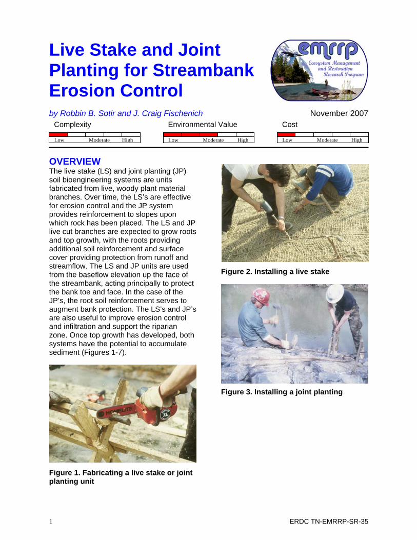
OVERVIEW The live stake (LS) and joint planting (JP) soil bioengineering systems are units fabricated from live, woody plant material branches. Over time, the LS’s are effective for erosion control and the JP system provides reinforcement to slopes upon which rock has been placed. The LS and JP live cut branches are expected to grow roots and top growth, with the roots providing additional soil reinforcement and surface cover providing protection from runoff and streamflow. The LS and JP units are used from the baseflow elevation up the face of the streambank, acting principally to protect the bank toe and face. In the case of the JP’s, the root soil reinforcement serves to augment bank protection. The LS’s and JP’s are also useful to improve erosion control and infiltration and support the riparian zone. Once top growth has developed, both systems have the potential to accumulate sediment (Figures 1-7).
Figure 1. Fabricating a live stake or joint planting unit
Figure 2. Installing a live stake
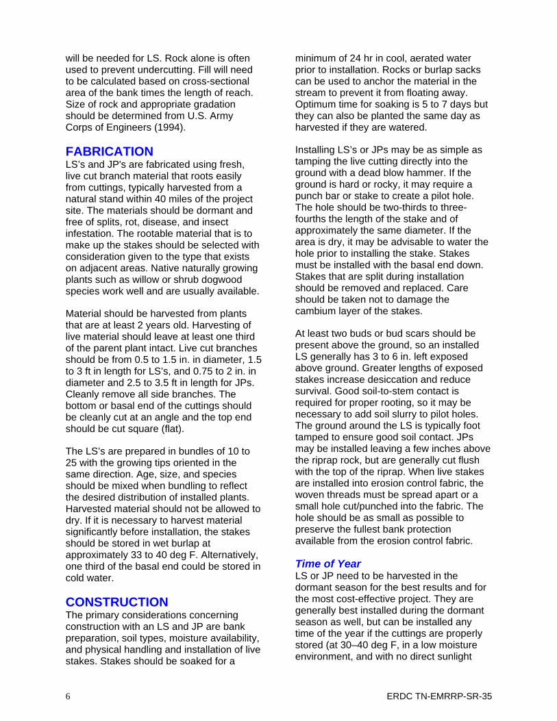
Figure 3. Installing a joint planting
1 ERDC TN-EMRRP-SR-35

Figure 4. An establishing live stake area
Figure 5. An establishing joint planting area
Figure 6. Development of a live stake installation
Figure 7. Illustration of the development of a joint planting installation
The LS and JP may improve aquatic habitat by providing food and cover in the riparian zone and over the water when they are used in close proximity to the edge of the stream. Stone used at the base of the LS or with JP produces substrates suited for an array of aquatic organisms. Some of these organisms adapt to living on and within the rocks and some attach to the leaves and stems. The leaves and stems may also become food for shredders.
Species for LS and JP systems can be selected to provide color, texture, and other attributes that add a pleasant, natural landscape appearance. Such plants for LS and JP systems include willow (Salix spp.), which tends to be the best from an adventitious rooting perspective and is normally an excellent choice. However other species such as poplar (Populus spp.), Viburnum spp., Hibiscus spp., shrub dogwood (Cornus spp.) and buttonbush (Cephalanthus), also work well. After establishment, the LS and JP systems can reduce non-point pollution by intercepting sediment and attached pollutants that otherwise enter the stream from overbank flow areas.
PLANNING The first step in the planning process is to determine whether an LS or JP system is an appropriate alternative to address the observed and projected mechanisms of bank loss. Questions that must be addressed include the following inter-related items (not exhaustive):
2 ERDC TN-EMRRP-SR-35

1. Is an LS or JP system an appropriate alternative given the magnitude of the erosion problem, e.g. its geomorphic and morphological characteristics?
2. Will the hydrology of the stream accommodate an LS or JP system that produces woody growth?
3. Are stream velocities and shear stresses permissible, and is the risk of ice and debris damage acceptable?
4. Will sediment accumulation be a positive or negative result for plant establishment and survival?
5. Will there be enough sunlight and water to support the desired system?
6. Are there riparian woody plants in a reference reach or nearby similar system that can be used as a template (and perhaps material source) for the construction of an LS or JP system?
7. Will site conditions during construction permit installation?
8. Have risks, and specifically the consequences of failure, been considered and what are they (e.g., what happens if the LS or JP system becomes dislodged and materials move downstream)?
9. What other erosion control devices or materials will be needed, such as grade control in the bed, a filter fabric or stone in the JP or an erosion control fabric (ECF) on the bank?
10. Is the required construction season available?
11. Is depredation a potential problem, or can it be controlled?
12. Are the costs acceptable?
CONSTRUCTION COSTS Costs for LS and JP projects are comparable to those for other bank
stabilization techniques. Following are Year 2001 cost ranges for LS and JP projects based on the authors’ experiences. These include profit margins and contingency factors on contractor bid projects.
The LS costs range from $3 to $10 each, while the JP costs range from $6 to $15 each. These prices include harvesting, transportation, handling, fabrication, and storage of the live cut branch materials. Costs for other system elements (e.g. riprap) and bank reshaping are not included. Costs may vary with access, availability of live material, time of year and prevailing labor rates. Fabrication of the LS or JP is simple and is performed either just prior to installation in moist climates and a week prior in dry areas. In dry areas, soaking the living stakes for a week in water improves survival. Both LS and JP structures may be fabricated in custom length for special needs. Installation is also relatively easy, as large equipment is not required except to slope back the bank. Fabrication and installation costs are usually low.
SITE CONSIDERATIONS A site suited to LS or JP treatments requires a hydrologic regime that 1) keeps the invert of the stake wet during most of the growing season where the establishment of woody plants are desirable; 2) allows the roots to reach the water table or vadose zone during most of the growing season; and 3) sustains flows sufficient to keep woody plants growing well but not large and long-duration of flows so as to exceed the plant’s flood tolerance. Given these requirements, streams best suited have perennial flows and are small to moderate in size, although the authors have successfully applied these treatments on a wide range of systems. Some variation in water surface elevation associated with baseflow is acceptable. However, the roots must have access to water.
The second most important factor in site selection is choosing a site that is not subject to massive amounts of sediment movement that could smother plants establishing on the bank. After they become
3 ERDC TN-EMRRP-SR-35

established, however, LS and JPs are effective in trapping soils from stream flows. They also establish conditions for subsequent colonization or planting, most often within the captured sediment. When LS's are used along a stream system, installation should follow the stabilization of the upper bank face using an appropriate erosion control fabric.
A site suited to LS or JP treatments must have adequate soil (growing medium) available to allow for root penetration. Lean clays and highly compacted soils inhibit root growth and generally result in poor success. Soil pH should be in the range of 6–8, and the soils should have sufficient nutrients or be augmented with a slow release fertilizer. Inoculation of the soils with mychorrizae to stimulate root growth is often helpful.
Other important considerations in site selections are shade conditions, type of substrate in which they will be placed, and their relation to the channel thalweg. Most plants that are desired for establishment are shade intolerant and require some sunlight. As a general rule, moderate sunlight exposure should exist for LS and JP structures. There are exceptions where shade-tolerant plants (e.g. viburnum) can be used, but success is often poor. Consult the Natural Resources Conservation Service offices for information on local plants suitable for the area of interest.
A cobble substrate or one laden with interspersed rock can require special equipment or materials to achieve penetration. LS’s and JP’s may be installed 1.5 to 4 ft deep and diameters in the 1- to 2-in. range are typically most successful, so driving these stakes into a hard substrate can be problematic. For highly erodible bank materials, LS should be protected with a stone toe buttress to prevent scour and undercutting and an erosion control material to prevent surficial erosion.
DESIGN Primary Design Considerations Depth of erosion must be in the range of 1 to 3 in. for the LS system to be an effective immediate erosion control method when used with erosion control fabric. Elevation of the LS and JP systems must be suited to the vegetation for which they provide substrate. In general, the LS or JP must be at an elevation that permits absorption of water from groundwater seepage from the bank to prevent desiccation of the vegetation. However, it must not be placed so low as to inundate the vegetation beyond its flood tolerance. When willow branches or other woody plants are used in LS or JP constructions, their basal ends are inserted well into a moist zone within the bank (Figures 2 and 3). There is no requirement for periodic wetting. In these cases, LS's are intended primarily to provide sediment and erosion control after the woody vegetation has become established.
The LS's or JPs are typically installed in a random pattern or in rows and spaced apart according to slope and soil conditions illustrated in Tables 1 and 2. On moist seeping banks, more LS's may be used to assist in moisture depletion.
Table 1. Live Stake Spacing Spacing – feet O.C.¹
Soils Slope Steepness² Cohesive Non-Cohesive
1:1 2 to 3 N/A 2:1 3 to 4 2 to 3 3:1 or flatter 4 to 6 3 to 5
¹ O.C. = On Center ² Assumes stable slope Note: Recommended to be used with an erosion control fabric
4 ERDC TN-EMRRP-SR-35

Table 2. Joint Planting Spacing Spacing – Feet O.C.¹
Soils Slope Steepness² Cohesive Non-Cohesive 1.5:1 N/A N/A 2:1 1.5 to 3 1.5 to 2 3:1 or flatter 3 to 5 2 to 4
¹ O.C. = On Center ² Assumes stable slope Note: All are recommended to be used with loose dumped riprap or evenly placed no deeper that 18” with filter fabric or filter stone in non-cohesive soils.
Only limited data have been collected for shear or velocity tolerances of LS and JP structures. Available data come largely from empirical information collected from constructed projects (Tables 3 and 4). Designers should exercise caution in considering limiting velocity or shear stress criteria. Failure of LS or JP structures can be attributed to several mechanisms, notably flanking, and undercutting.
Table 3. Live Stakes in Bare Soil Before Established Soils Velocity, ft/sec Shear, lb/ft Silts .05 .001 Sands .5 .01 Large Gravel 2 .5 Large Cobble 4 2 Firm Loam 2.5 .08 Stiff Clays 3 - 4 .25 12” Rounded Riprap
6 4
Table 4. Live Stakes with Erosion Control Fabrics Prior to and After Establishment Fabric Velocity, ft/sec Shear, lb/ftJute Before Est. 1 – 2.5 .45 After Est. 3 – 7 2.1 – 3.1 Woven Coir – 700gm wt.
Before Est. 3 – 5 2 – 2.5 After Est. 3 - 10 2.1 – 3.1
Success for both LS’s and JP’s requires that protection be provided against undercutting and flanking of the treatment. For toe and flank protection, rock protection should be designed for velocities and shear stresses exceeding allowable limits for the soils and rock underlying and within the LS or JP. Fischenich (2001) presents these limits. Angular rock is recommended and should be sized in accordance with the U.S. Army Corps of Engineers (1994) specifications depending on anticipated velocities and shear stress.
Flank protection can also be aided by keying the ends of the LS or JP systems into the banks at both ends and protecting the flanks with a rock protection. Key ends well into the bank with rock on the upstream side, which is also keyed into the bank. For banks susceptible to significant erosion, keys or refusals extend farther into the bank.
Table 5. Threshold Conditions Class Name
DS (IN)
φ (DEG) τ’C
τC (LB/SF)
VC (FT/S)
Boulder Very large >80 42 0.054 37.4 25 Large >40 42 0.054 18.7 19 Medium >20 42 0.054 9.3 14 Small >10 42 0.054 4.7 10 Cobble Large >5 42 0.054 2.3 7 Small >2.5 41 0.052 1.1 5 Gravel Very coarse
>1.25 40 0.050 0.54 3
Coarse >0.63 38 0.047 0.25 2.5
Other Design Considerations Other design considerations, including the length of bank and face width being eroded, will determine the length of the treatment needed.
Eroded banks are not always conducive to immediate LS or JP installation and typically require reshaping or filling treatment to accommodate the use of LS or JP installation. If fill is required, rock fill mixed with other substrate suitable for plant growth
5 ERDC TN-EMRRP-SR-35
will be needed for LS. Rock alone is often used to prevent undercutting. Fill will need to be calculated based on cross-sectional area of the bank times the length of reach. Size of rock and appropriate gradation should be determined from U.S. Army Corps of Engineers (1994).
FABRICATION LS’s and JP's are fabricated using fresh, live cut branch material that roots easily from cuttings, typically harvested from a natural stand within 40 miles of the project site. The materials should be dormant and free of splits, rot, disease, and insect infestation. The rootable material that is to make up the stakes should be selected with consideration given to the type that exists on adjacent areas. Native naturally growing plants such as willow or shrub dogwood species work well and are usually available.
Material should be harvested from plants that are at least 2 years old. Harvesting of live material should leave at least one third of the parent plant intact. Live cut branches should be from 0.5 to 1.5 in. in diameter, 1.5 to 3 ft in length for LS’s, and 0.75 to 2 in. in diameter and 2.5 to 3.5 ft in length for JPs. Cleanly remove all side branches. The bottom or basal end of the cuttings should be cleanly cut at an angle and the top end should be cut square (flat).
The LS’s are prepared in bundles of 10 to 25 with the growing tips oriented in the same direction. Age, size, and species should be mixed when bundling to reflect the desired distribution of installed plants. Harvested material should not be allowed to dry. If it is necessary to harvest material significantly before installation, the stakes should be stored in wet burlap at approximately 33 to 40 deg F. Alternatively, one third of the basal end could be stored in cold water.
CONSTRUCTION The primary considerations concerning construction with an LS and JP are bank preparation, soil types, moisture availability, and physical handling and installation of live stakes. Stakes should be soaked for a
minimum of 24 hr in cool, aerated water prior to installation. Rocks or burlap sacks can be used to anchor the material in the stream to prevent it from floating away. Optimum time for soaking is 5 to 7 days but they can also be planted the same day as harvested if they are watered.
Installing LS’s or JPs may be as simple as tamping the live cutting directly into the ground with a dead blow hammer. If the ground is hard or rocky, it may require a punch bar or stake to create a pilot hole. The hole should be two-thirds to three-fourths the length of the stake and of approximately the same diameter. If the area is dry, it may be advisable to water the hole prior to installing the stake. Stakes must be installed with the basal end down. Stakes that are split during installation should be removed and replaced. Care should be taken not to damage the cambium layer of the stakes.
At least two buds or bud scars should be present above the ground, so an installed LS generally has 3 to 6 in. left exposed above ground. Greater lengths of exposed stakes increase desiccation and reduce survival. Good soil-to-stem contact is required for proper rooting, so it may be necessary to add soil slurry to pilot holes. The ground around the LS is typically foot tamped to ensure good soil contact. JPs may be installed leaving a few inches above the riprap rock, but are generally cut flush with the top of the riprap. When live stakes are installed into erosion control fabric, the woven threads must be spread apart or a small hole cut/punched into the fabric. The hole should be as small as possible to preserve the fullest bank protection available from the erosion control fabric.
Time of Year LS or JP need to be harvested in the dormant season for the best results and for the most cost-effective project. They are generally best installed during the dormant season as well, but can be installed any time of the year if the cuttings are properly stored (at 30–40 deg F, in a low moisture environment, and with no direct sunlight
6 ERDC TN-EMRRP-SR-35

exposure). Installation into frozen or heavily frosted soils is difficult, at best, so late fall and early spring are the preferred installation times throughout most of the United States.
OPERATION AND MAINTENANCE Operation and maintenance requirements of any soil bioengineering treatment will vary depending on the stream system and its associated parameters, such as velocity, flood frequency, flood stage, timing, and future planned use. In any case, be prepared, at least early in the project life, to repair or augment the systems until the vegetation becomes well established. Minimally, inspection should occur after each of the first few floods and/or at least twice a year the first year and once a year thereafter, preferably after the predominant flood season.
Immediately repair observed undercutting and flanking of the treatment and any other substantial scour evidence. Examine the live cuttings in the LS or JP for adequate survival and growth and absence of disease, insect, or other animal damage (e.g., grazing, trampling, digging, eating, and cutting). Successful plants will grow vigorously and spread their roots into the surrounding substrate.
If animal or human trampling damage is evident or the plants are being removed or eaten by waterfowl or beavers, preventative measures such as exclosures may be required. Such exclosures, especially for woody plants, may only need to be used until the vegetation is well established (1 to 3 years).
Assuming the LS and/or JP remains in place and vegetation becomes established through the development of growth from the live cutting or through plant development from natural invasion, maintenance becomes less over time.
Fish and aquatic invertebrate sampling is always recommended both before installation to gather base information and
after the installation has become established (1 to 3 years), to determine habitat improvement effectiveness.
APPLICABILITY AND LIMITATIONS Techniques described in this technical note are generally applicable where primary objectives for streams include habitat diversity, erosion control, water quality improvement, and aesthetics, including a diversity of riparian plants along the streambank. LS or JP systems are expected to establish on a wide range of streams having fairly constant and consistent base flows as well as ephemeral stream systems. However, vegetation may tend to dry out and die in extreme conditions and where installations are not deep enough to allow roots to reach adequate moisture. This may be especially true for JPs. Streams should not have excessive sediment loads that may completely cover and smother the establishing LS or JP. Some caution is also needed when selecting the species for LS or JP.
Exercise caution in using JP or LS without a rock protection or other hard material when stream velocities at the bank exceed critical thresholds for underlying soils.
Trampling and grazing of LS can be detrimental from a living perspective. Use may be limited in areas where cattle grazing is not restricted. Note that due to safety, live stakes are not recommended over the bank in high traffic areas where people may trip and fall on them.
Consider the time of year when installing LS’s or JPs as well as water elevation. Consider consequences of failure if an LS or JP is flanked and washed downstream and if the failure is likely to create hazards that otherwise would not occur (e.g., trapping debris and causing undesired local scour, current deflection, and damming).
7 ERDC TN-EMRRP-SR-35

8 ERDC TN-EMRRP-SR-35
ACKNOWLEDGEMENTS Research presented in this technical note was developed under the U.S. Army Corps of Engineers Ecosystem Management and Restoration Research Program. Technical reviews were provided by Messrs. Jim Henderson and Jock Conyngham of the Environmental Laboratory, U.S. Army Engineer Research and Development Center.
POINTS OF CONTACT For additional information, contact the authors, Robbin B. Sotir (770-424-0719), [email protected]) or Dr. J. Craig Fischenich, (601-634-3449, [email protected]), or the manager of the Ecosystem Management and Restoration Research Program, Glenn Rhett (601-634-3717, [email protected]). This technical note should be cited as follows:
Sotir, R. B., and J. C. Fischenich. 2007. Live stake and joint planting for streambank erosion control. EMRRP Technical Notes Collection. ERDC TN-EMRRP-SR-35. Vicksburg, MS: U.S. Army Engineer Research and Development Center. www.wes.army.mil/el/emrrp.
REFERENCES Fischenich, C. 2001. Stability thresholds for stream restoration materials. EMRRP Technical Notes Collection. ERDC TN-EMRRP-SR-29. Vicksburg, MS: U.S. Army Engineer Research and Development Center. www.wes.army.mil/el/emrrp.
U.S. Army Corps of Engineers. 1994. Hydraulic design of flood control channels. Engineer Manual 1110-2-1601, Change 1, 30 June 1994. Washington, DC.