cylindrical free-standing mode triboelectric generator for ...nesel.skku.edu/paper...
TRANSCRIPT

micromachines
Article
Cylindrical Free-Standing Mode TriboelectricGenerator for Suspension System in Vehicle
Minki Kang 1, Tae Yun Kim 1 , Wanchul Seung 1, Jae-Hee Han 2 and Sang-Woo Kim 1,*1 School of Advanced Materials Science and Engineering, Sungkyunkwan University (SKKU), Suwon 16419,
Korea; [email protected] (M.K.); [email protected] (T.Y.K.); [email protected] (W.S.)2 Department of Energy IT, Gachon University, Seongnam 13120, Korea; [email protected]* Correspondence: [email protected]; Tel.: +82-31-290-7632
Received: 20 November 2018; Accepted: 18 December 2018; Published: 29 December 2018
Abstract: The triboelectric generator (TEG) is a strong candidate for low-power sensors utilized inthe Internet of Things (IoT) technology. Within IoT technologies, advanced driver assistance system(ADAS) technology is included within autonomous driving technology. Development of an energysource for sensors necessary for operation becomes an important issue, since a lot of sensors areembedded in vehicles and require more electrical energy. Although saving energy and enhancingenergy efficiency is one of the most important issues, the application approach to harvesting wastedenergy without compromising the reliability of existing mechanical systems is still in very earlystages. Here, we report of a new type of TEG, a suspension-type free-standing mode TEG (STEG)inspired from a shock absorber in a suspension system. We discovered that the optimum width ofelectrode output voltage was 131.9 V and current was 0.060 µA/cm2 in root mean square (RMS)value while the optimized output power was 4.90 µW/cm2 at 66 MΩ. In addition, output power wasfound to be proportional to frictional force due to the contact area between two frictional surfaces. Itwas found that the STEG was made of perfluoroalkoxy film and showed good mechanical durabilitywith no degradation of output performance after sliding 11,000 times. In addition, we successfullydemonstrated charging a capacitor of 330 µF in 6 min.
Keywords: triboelectric generator; shock absorber; suspension system; advanced driver assistancetechnology; IoT technology; frictional force
1. Introduction
Internet of Things (IoT) technology is becoming more influential within our lives recently. Thistechnology, which is based on wireless sensor network systems, has comprehensive applications, suchas health monitoring, smart factories, autonomous driving, etc. Among them, autonomous driving isone of the most promising technologies. As an intermediate stage, a number of automotive companiesare trying to develop advanced driver assistance system (ADAS) technology to realize autonomousdriving vehicles. As ADAS technology is based on sensor network systems, continuous power supplyfor stable and long-term operation of sensors is very important. Although individual sensors for sensornetworks consume relatively small amounts of energy, ranging from µW to mW, large amounts ofenergy would be required for the sustainable operation of a huge number of sensors assembled inan IoT system [1,2]. However, current automotive energy harvesting technologies based on traditionalelectro-magnetic induction are not efficient for powering sensors because of their heavy weight whencompared to their output performance, and thus the absence of an efficient energy source for the sensornetwork system, not only leads to a reduction in energy efficiency of the vehicle, but also disturbs thepractical application of ADAS technology in a vehicle [3,4].
Micromachines 2019, 10, 17; doi:10.3390/mi10010017 www.mdpi.com/journal/micromachines
Micromachines 2019, 10, 17 2 of 9
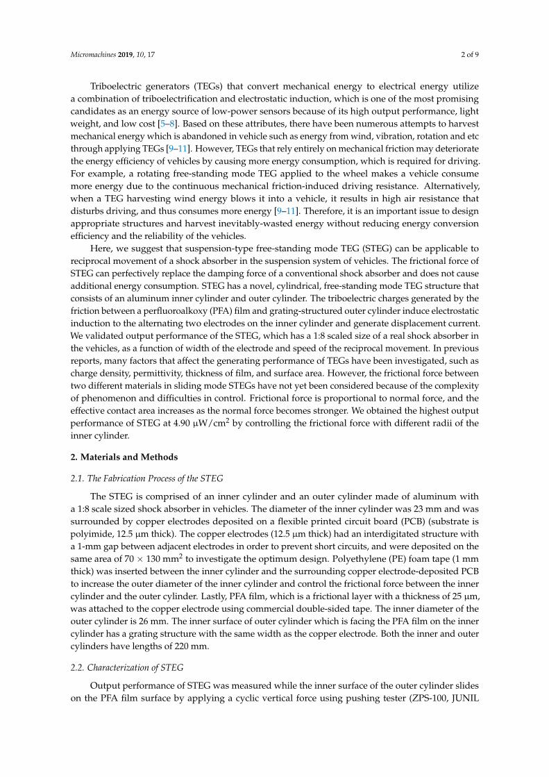
Triboelectric generators (TEGs) that convert mechanical energy to electrical energy utilizea combination of triboelectrification and electrostatic induction, which is one of the most promisingcandidates as an energy source of low-power sensors because of its high output performance, lightweight, and low cost [5–8]. Based on these attributes, there have been numerous attempts to harvestmechanical energy which is abandoned in vehicle such as energy from wind, vibration, rotation and etcthrough applying TEGs [9–11]. However, TEGs that rely entirely on mechanical friction may deterioratethe energy efficiency of vehicles by causing more energy consumption, which is required for driving.For example, a rotating free-standing mode TEG applied to the wheel makes a vehicle consumemore energy due to the continuous mechanical friction-induced driving resistance. Alternatively,when a TEG harvesting wind energy blows it into a vehicle, it results in high air resistance thatdisturbs driving, and thus consumes more energy [9–11]. Therefore, it is an important issue to designappropriate structures and harvest inevitably-wasted energy without reducing energy conversionefficiency and the reliability of the vehicles.
Here, we suggest that suspension-type free-standing mode TEG (STEG) can be applicable toreciprocal movement of a shock absorber in the suspension system of vehicles. The frictional force ofSTEG can perfectively replace the damping force of a conventional shock absorber and does not causeadditional energy consumption. STEG has a novel, cylindrical, free-standing mode TEG structure thatconsists of an aluminum inner cylinder and outer cylinder. The triboelectric charges generated by thefriction between a perfluoroalkoxy (PFA) film and grating-structured outer cylinder induce electrostaticinduction to the alternating two electrodes on the inner cylinder and generate displacement current.We validated output performance of the STEG, which has a 1:8 scaled size of a real shock absorber inthe vehicles, as a function of width of the electrode and speed of the reciprocal movement. In previousreports, many factors that affect the generating performance of TEGs have been investigated, such ascharge density, permittivity, thickness of film, and surface area. However, the frictional force betweentwo different materials in sliding mode STEGs have not yet been considered because of the complexityof phenomenon and difficulties in control. Frictional force is proportional to normal force, and theeffective contact area increases as the normal force becomes stronger. We obtained the highest outputperformance of STEG at 4.90 µW/cm2 by controlling the frictional force with different radii of theinner cylinder.
2. Materials and Methods
2.1. The Fabrication Process of the STEG
The STEG is comprised of an inner cylinder and an outer cylinder made of aluminum witha 1:8 scale sized shock absorber in vehicles. The diameter of the inner cylinder was 23 mm and wassurrounded by copper electrodes deposited on a flexible printed circuit board (PCB) (substrate ispolyimide, 12.5 µm thick). The copper electrodes (12.5 µm thick) had an interdigitated structure witha 1-mm gap between adjacent electrodes in order to prevent short circuits, and were deposited on thesame area of 70 × 130 mm2 to investigate the optimum design. Polyethylene (PE) foam tape (1 mmthick) was inserted between the inner cylinder and the surrounding copper electrode-deposited PCBto increase the outer diameter of the inner cylinder and control the frictional force between the innercylinder and the outer cylinder. Lastly, PFA film, which is a frictional layer with a thickness of 25 µm,was attached to the copper electrode using commercial double-sided tape. The inner diameter of theouter cylinder is 26 mm. The inner surface of outer cylinder which is facing the PFA film on the innercylinder has a grating structure with the same width as the copper electrode. Both the inner and outercylinders have lengths of 220 mm.
2.2. Characterization of STEG
Output performance of STEG was measured while the inner surface of the outer cylinder slideson the PFA film surface by applying a cyclic vertical force using pushing tester (ZPS-100, JUNIL

Micromachines 2019, 10, 17 3 of 9
TECH Co., Ltd., Seoul, Korea). The inner cylinder was fixed on the bottom stage and the outercylinder was attached to the moving part, which periodically moved with a constant speed of 62.5, 140,and 200 mm/s, respectively, and the period was 0.4 s for all cases. During movement, the frictionalforce controlled by PE foam tape was measured using a force sensor installed in the pushing tester.The output voltage between two interdigitated electrodes was measured using an oscilloscope (DPO3052, Tektronix, Beaverton, OR, USA) with an input impedance of 40 MΩ, and the output currentwas measured using a current amplifier (DLPCA-200, FEMTO, Berlin, Germany) connected to theoscilloscope under short circuit conditions. After 11,000 periodic movements with a frictional forceof 0.6 kgf, the surface morphology of PFA film was examined using scanning electron microscopy(JSM-6701F, FE-SEM, Jeol Ltd., Mitaka, Tokyo, Japan) to check mechanical durability.
3. Results
3.1. Geometrical Design of the STEG and Electrical Performance
The STEG was designed based on the structure of a free-standing mode TEG, in which the copperelectrodes on the inner cylinder and outer cylinder corresponded to alternative electrodes and movingobjects, respectively. For the investigation and fabrication of a STEG that is compatible with the currentsuspension systems in vehicles, the materials were selected to satisfy, not only the triboelectric series,which indicates how much the material has tendency to have a positive or negative surface charge, butalso to maintain the reliability of the suspension system.
The schematic structure and triboelectric energy regenerative suspension application is featuredin Figure 1a. Each cylinder was made of aluminum, and flexible PCB comprised of polyimide (PI)substrate and alternating copper electrodes was covered by a perfluoroalkoxy film (PFA) on the innercylinder. Optical images, material, and structure of STEG are shown in Figure S1. The outer cylinderhad a grating structure on the inner surface and a slide along the PFA film, generating triboelectriccharges. The size of the cylinder was 1:8 scaled size compared to commercial shock absorbers in thesuspension systems of vehicles.
The working mechanism of STEG is based on that of a free-standing mode TEG and is illustratedin Figure 1a(i)–(iii) [12]. The sliding motion of two cylinders leads to triboelectrification due to thefriction between the PFA film and the outer cylinder. Subsequently, the PFA film and aluminumouter cylinder have opposite negative and positive charges on their surfaces, respectively, due totheir different triboelectric polarities and the amount of transferred opposite charges was saturated.The surface charge density of the outer cylinder was twice the surface charge density of the PFA filmaccording to the law of charge conservation, because the contact area of the outer cylinder is two timessmaller than that of PFA film. Under the short-circuit conditions, when the outer cylinder was placedon electrode A, the electrical potential difference between the two electrodes was positively maximized(i). When the outer cylinder slid and was placed between electrode A and B, the current flowed fromelectrode A to electrode B to compensate for the electrostatic induction and made the electrical potentialof electrode A equal to that of electrode B (ii). Subsequently, when the outer cylinder reaches electrodeB, the electrical potential difference between the two electrodes would be negatively maximized (iii).These stages would be repeated by reciprocating motion of cylinders. PFA film is known to have,not only the most negativity in triboelectric series (so that the largest amount of charges is generatedby triboelectrification), but also abrasion resistance and mechanical durability [13–15]. The noveltriboelectric and mechanical properties of PFA allow for STEG to have a high output performance witha very long lifetime [16,17]. During reciprocating movement of the outer cylinder with a displacementof 50 mm and speed of 100 mm/s, STEG generated a maximum voltage and current of 100 V and0.014 µA/cm2, respectively, when the damping force was 0.6 kgf and the width of electrode A and Bwere 3 mm (Figure 1b,c). Since STEG had a cylindrical shape and a frictional force against mechanicalmovement, it could take a role of a damper for the applied force as well as energy harvester. This

Micromachines 2019, 10, 17 4 of 9
point is very important because it means that STEG can harvest wasted energy without unnecessaryenergy consumption.
In order to optimize the output performance of STEG, we investigated the dependence of theoutput performance on geometrical parameters, such as electrode width. We fabricated several STEGswith different widths of copper electrodes (from 1 mm to 7 mm), but the same gap distance of 1 mmbetween adjacent electrodes. The output voltage and current were measured by sliding the outercylinder of each STEG at 200 mm/s, with a damping force of 0.6 kgf and displacement of 50 mm, asshown in Figure 2a. Output voltage and current increased as the electrode width increases from 1 mmto 3 mm, showing a maximum value of 131.9 V and 0.060 µA/cm2 in root mean square (RMS) value,respectively. However, output voltage and current decreased as the electrode width increased over3 mm.
The dependence of the output performance on the electrode width in the experimental resultswas verified using numerical simulations with the same geometric modeling as the experiment.Each electrode, of which the electrode widths were 1, 3, 5, and 7 mm was periodically arrayed andterminated as alternating electrode A and B. The gap distance between neighboring electrodes was1 mm, and between the moving object and bottom electrode was 25 µm. Experimentally, there wasPFA film between the top and bottom electrodes, and triboelectric charges existed on the top surface ofthe PFA film; however, for simplification, PFA film was not considered and the triboelectric charges(25 µC/m2) existed on the bottom surface of the moving object. For calculating the electric voltagebetween electrodes A and B, while the top object was moving at 50 mm/s, the electrical circuitmodule was coupled. The resistance of the electrical circuit module was set to 100 GΩ for open-circuitconditions. RMS voltage values of devices with different electrode widths are compared in Figure 2b.Corresponding to the experimental results, simulation results showed the highest voltage value whenthe electrode width was 3 mm. With a fixed gap distance between the electrodes (1 mm), the electrodeswere more separated from neighboring electrodes as the width decreased. In the case of an electricfield from the charged plane, the electric voltage was proportional to distance; thus, electric voltageincreased as electrode width decreased. However, the electrode has finite area, so the edge effectshould be considered. As the electrode width decreased, the edge effect became larger compared withthe electric field from the charged plane; thus, the electric field became smaller [18,19]. Consideringthese two effects, 3 mm was the optimum width of the electrode for the highest output performance.The experimental raw data and simulation results related to structure-dependent electric field areillustrated in Figure S2.
Theoretical study on the electric fields in the different geometries offer us an understanding of thereason why STEG could have high output characteristics. To compare the intensity of electric fieldsand the potential difference versus geometry of the free-standing mode TEG, a COMSOL simulationwas conducted on the planar and cylindrical models with the same area and charge density (Figure S3).When the planar model has the geometry infinity plane, the edge effect could be ignored. However, theedge effect is not negligible as there is a non-continuous adjacent charge at the edge of the plane [20].This characteristic of the planar model induced decreases in the electric field and potential difference(Figure S3a). On the other hand, in the case of a cylindrical model, the edge effect was negligiblebecause the electric field was distributed radially so that they had higher potential differences with thesame area and charge density (Figure S3b). A cross-sectional profile of the electrical potential along thesurface is compared in Figure S3c. The cylindrical charged surface exhibits larger potential than theplanar charged surface and the difference is 100 V or more.

Micromachines 2019, 10, 17 5 of 9
Micromachines 2018, 9, x FOR PEER REVIEW 4 of 9
In order to optimize the output performance of STEG, we investigated the dependence of the output performance on geometrical parameters, such as electrode width. We fabricated several STEGs with different widths of copper electrodes (from 1 mm to 7 mm), but the same gap distance of 1 mm between adjacent electrodes. The output voltage and current were measured by sliding the outer cylinder of each STEG at 200 mm/s, with a damping force of 0.6 kgf and displacement of 50 mm, as shown in Figure 2a. Output voltage and current increased as the electrode width increases from 1 mm to 3 mm, showing a maximum value of 131.9 V and 0.060 µA/cm2 in root mean square (RMS) value, respectively. However, output voltage and current decreased as the electrode width increased over 3 mm.
The dependence of the output performance on the electrode width in the experimental results was verified using numerical simulations with the same geometric modeling as the experiment. Each electrode, of which the electrode widths were 1, 3, 5, and 7 mm was periodically arrayed and terminated as alternating electrode A and B. The gap distance between neighboring electrodes was 1 mm, and between the moving object and bottom electrode was 25 µm. Experimentally, there was PFA film between the top and bottom electrodes, and triboelectric charges existed on the top surface of the PFA film; however, for simplification, PFA film was not considered and the triboelectric charges (25 µC/m2) existed on the bottom surface of the moving object. For calculating the electric voltage between electrodes A and B, while the top object was moving at 50 mm/s, the electrical circuit module was coupled. The resistance of the electrical circuit module was set to 100 GΩ for open-circuit conditions. RMS voltage values of devices with different electrode widths are compared in Figure 2b. Corresponding to the experimental results, simulation results showed the highest voltage value when the electrode width was 3 mm. With a fixed gap distance between the electrodes (1 mm), the electrodes were more separated from neighboring electrodes as the width decreased. In the case of an electric field from the charged plane, the electric voltage was proportional to distance; thus, electric voltage increased as electrode width decreased. However, the electrode has finite area, so the edge effect should be considered. As the electrode width decreased, the edge effect became larger compared with the electric field from the charged plane; thus, the electric field became smaller [18,19]. Considering these two effects, 3 mm was the optimum width of the electrode for the highest output performance. The experimental raw data and simulation results related to structure-dependent electric field are illustrated in Figure S2.
Figure 1. (a) Schematic structure and triboelectric regenerative suspension application and the workingmechanism of a suspension-type free-standing mode triboelectric generator (STEG); (b) the outputvoltage and (c) short-circuit current according to the reciprocating movement of the outer cylinder witha displacement of 50 mm and speed of 100 mm/s.
Micromachines 2018, 9, x FOR PEER REVIEW 5 of 9
Figure 1. (a) Schematic structure and triboelectric regenerative suspension application and the working mechanism of a suspension-type free-standing mode triboelectric generator (STEG); (b) the output voltage and (c) short-circuit current according to the reciprocating movement of the outer cylinder with a displacement of 50 mm and speed of 100 mm/s.
Figure 2. Output performance evaluation and simulation versus electrode width: (a) output voltage and short-circuit current; (b) COMSOL simulation result (open-circuit voltage) with a resistance of 100 GΩ for open-circuit condition; (c) output power in root mean square (RMS) value and different optimum resistance according to changes in the electrode width.
Theoretical study on the electric fields in the different geometries offer us an understanding of the reason why STEG could have high output characteristics. To compare the intensity of electric fields and the potential difference versus geometry of the free-standing mode TEG, a COMSOL simulation was conducted on the planar and cylindrical models with the same area and charge density (Figure S3). When the planar model has the geometry infinity plane, the edge effect could be ignored. However, the edge effect is not negligible as there is a non-continuous adjacent charge at the edge of the plane [20]. This characteristic of the planar model induced decreases in the electric field and potential difference (Figure S3a). On the other hand, in the case of a cylindrical model, the edge effect was negligible because the electric field was distributed radially so that they had higher potential differences with the same area and charge density (Figure S3b). A cross-sectional profile of the electrical potential along the surface is compared in Figure S3c. The cylindrical charged surface exhibits larger potential than the planar charged surface and the difference is 100 V or more.
In addition, we determined that each STEG with electrode widths of 1, 3, 5, and 7 mm had different optimum resistances of 44 MΩ, 66 MΩ, 220 MΩ, and 330 MΩ, respectively, as depicted in Figure 2c. As a result, the STEG with an electrode width of 3 mm could generate 4.90 µW/cm2 at 66 MΩ. Electrical impedance of the capacitor was inversely proportional to the frequency and capacitance [12,21]. As the electrode width increased, it takes more time for a contacting part of the outer cylinder to move from electrode A to B; as such, the frequency decreased at the same speed when the effective gap between neighboring electrodes increased. Therefore, the optimum electric impedance of STEG increased as a function of electrode width.
3.2. Evaluation of Output Performance depending on Mechanical Input Parameters
Faster speeds of reciprocating movements induced higher output performances because of the short-period of electrostatic induction. The output measurements according to changes in the speed were conducted for STEG, which has a damping force of 0.6 kgf when the displacement is 50 mm and the electrode width is 3 mm (Figure 3a,b). As a result, we found that the maximum short-circuit current and output voltage of 0.060 µA/cm2 and 131.9 V, respectively, in RMS values could be acquired under a speed of 200 mm/s (Figure 3c). According to reference, which dealt with energy regenerative suspension, the RMS speed of the shock absorber and the speed of a vehicle have a proportional relationship. Through the conversion operation from the speed of the shock absorber to that of a vehicle, the expected short-circuit current in average city driving (32.2 km/h) is about 0.053 µA/cm2 in RMS value. Although the frictional force is one of the notable factors that has a great influence on the output performance of TEGs, experimental and theoretical studies have not
106 107 108 109
0
2
4
6
1 mm 3 mm 5 mm 7 mm
1 3 5 7400
420
440
460
480
500
A B A B
Width
a c
1 3 5 7
0
50
100
150
200
0.00
0.01
0.02
0.03
0.04
0.05
0.06
V RM
S(V
)
I RMS(
μA/c
m2 )
Electrode width (mm)
P RM
S(μ
W/c
m2 )
Resistance (ohm)
b
V RM
S(V
)
Electrode width (mm)
Figure 2. Output performance evaluation and simulation versus electrode width: (a) output voltageand short-circuit current; (b) COMSOL simulation result (open-circuit voltage) with a resistance of100 GΩ for open-circuit condition; (c) output power in root mean square (RMS) value and differentoptimum resistance according to changes in the electrode width.
In addition, we determined that each STEG with electrode widths of 1, 3, 5, and 7 mm haddifferent optimum resistances of 44 MΩ, 66 MΩ, 220 MΩ, and 330 MΩ, respectively, as depictedin Figure 2c. As a result, the STEG with an electrode width of 3 mm could generate 4.90 µW/cm2
at 66 MΩ. Electrical impedance of the capacitor was inversely proportional to the frequency andcapacitance [12,21]. As the electrode width increased, it takes more time for a contacting part of theouter cylinder to move from electrode A to B; as such, the frequency decreased at the same speedwhen the effective gap between neighboring electrodes increased. Therefore, the optimum electricimpedance of STEG increased as a function of electrode width.
Micromachines 2019, 10, 17 6 of 9
3.2. Evaluation of Output Performance depending on Mechanical Input Parameters
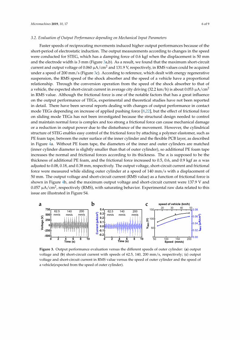
Faster speeds of reciprocating movements induced higher output performances because of theshort-period of electrostatic induction. The output measurements according to changes in the speedwere conducted for STEG, which has a damping force of 0.6 kgf when the displacement is 50 mmand the electrode width is 3 mm (Figure 3a,b). As a result, we found that the maximum short-circuitcurrent and output voltage of 0.060 µA/cm2 and 131.9 V, respectively, in RMS values could be acquiredunder a speed of 200 mm/s (Figure 3c). According to reference, which dealt with energy regenerativesuspension, the RMS speed of the shock absorber and the speed of a vehicle have a proportionalrelationship. Through the conversion operation from the speed of the shock absorber to that ofa vehicle, the expected short-circuit current in average city driving (32.2 km/h) is about 0.053 µA/cm2
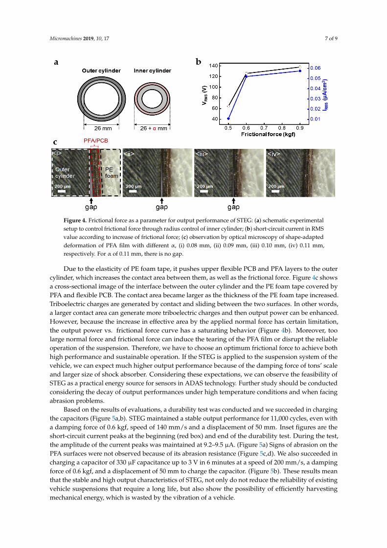
in RMS value. Although the frictional force is one of the notable factors that has a great influenceon the output performance of TEGs, experimental and theoretical studies have not been reportedin detail. There have been several reports dealing with changes of output performance in contactmode TEGs depending on increase of applied pushing force [8,22], but the effect of frictional forceon sliding mode TEGs has not been investigated because the structural design needed to controland maintain normal force is complex and too strong a frictional force can cause mechanical damageor a reduction in output power due to the disturbance of the movement. However, the cylindricalstructure of STEG enables easy control of the frictional force by attaching a polymer elastomer, such asPE foam tape, between the outer surface of the inner cylinder and the flexible PCB layer, as describedin Figure 4a. Without PE foam tape, the diameters of the inner and outer cylinders are matched(inner cylinder diameter is slightly smaller than that of outer cylinder), so additional PE foam tapeincreases the normal and frictional forces according to its thickness. The α is supposed to be thethickness of additional PE foam, and the frictional force increased to 0.5, 0.6, and 0.9 kgf as α wasadjusted to 0.08, 0.18, and 0.38 mm, respectively. The output voltage, short-circuit current and frictionalforce were measured while sliding outer cylinder at a speed of 140 mm/s with a displacement of50 mm. The output voltage and short-circuit current (RMS value) as a function of frictional force isshown in Figure 4b, and the maximum output voltage and short-circuit current were 137.9 V and0.057 µA/cm2, respectively (RMS), with saturating behavior. Experimental raw data related to thisissue are illustrated in Figure S4.
Micromachines 2018, 9, x FOR PEER REVIEW 6 of 9
been reported in detail. There have been several reports dealing with changes of output performance in contact mode TEGs depending on increase of applied pushing force [8,22], but the effect of frictional force on sliding mode TEGs has not been investigated because the structural design needed to control and maintain normal force is complex and too strong a frictional force can cause mechanical damage or a reduction in output power due to the disturbance of the movement. However, the cylindrical structure of STEG enables easy control of the frictional force by attaching a polymer elastomer, such as PE foam tape, between the outer surface of the inner cylinder and the flexible PCB layer, as described in Figure 4a. Without PE foam tape, the diameters of the inner and outer cylinders are matched (inner cylinder diameter is slightly smaller than that of outer cylinder), so additional PE foam tape increases the normal and frictional forces according to its thickness. The α is supposed to be the thickness of additional PE foam, and the frictional force increased to 0.5, 0.6, and 0.9 kgf as α was adjusted to 0.08, 0.18, and 0.38 mm, respectively. The output voltage, short-circuit current and frictional force were measured while sliding outer cylinder at a speed of 140 mm/s with a displacement of 50 mm. The output voltage and short-circuit current (RMS value) as a function of frictional force is shown in Figure 4b, and the maximum output voltage and short-circuit current were 137.9 V and 0.057 µA/cm2, respectively (RMS), with saturating behavior. Experimental raw data related to this issue are illustrated in Figure S4.
Figure 3. Output performance evaluation versus the different speeds of outer cylinder: (a) output voltage and (b) short-circuit current with speeds of 62.5, 140, 200 mm/s, respectively; (c) output voltage and short-circuit current in RMS value versus the speed of outer cylinder and the speed of a vehicle(expected from the speed of outer cylinder).
Figure 4. Frictional force as a parameter for output performance of STEG: (a) schematic experimental setup to control frictional force through radius control of inner cylinder; (b) short-
a
0 2 4 6 8 10-0.2-0.10.00.10.20.30.4
Cur
rent
(μA/
cm2 )
Time (s)0 2 4 6 8 10
-500
-250
0
250
500
750
Volta
ge (V
)
Time (s)
62.5 mm/s
140 mm/s
200 mm/s
62.5 mm/s
140 mm/s
200 mm/s
b c
50 100 150 2000
50
100
150
0.00
0.02
0.04
0.06
0.08
V RM
S(V
)
Speed (mm/s)
I RMS
(μA/
cm2 )
speed of vehicle (km/h)20 30 40 50
Figure 3. Output performance evaluation versus the different speeds of outer cylinder: (a) outputvoltage and (b) short-circuit current with speeds of 62.5, 140, 200 mm/s, respectively; (c) outputvoltage and short-circuit current in RMS value versus the speed of outer cylinder and the speed ofa vehicle(expected from the speed of outer cylinder).
Micromachines 2019, 10, 17 7 of 9
Micromachines 2018, 9, x FOR PEER REVIEW 6 of 9
been reported in detail. There have been several reports dealing with changes of output performance in contact mode TEGs depending on increase of applied pushing force [8,22], but the effect of frictional force on sliding mode TEGs has not been investigated because the structural design needed to control and maintain normal force is complex and too strong a frictional force can cause mechanical damage or a reduction in output power due to the disturbance of the movement. However, the cylindrical structure of STEG enables easy control of the frictional force by attaching a polymer elastomer, such as PE foam tape, between the outer surface of the inner cylinder and the flexible PCB layer, as described in Figure 4a. Without PE foam tape, the diameters of the inner and outer cylinders are matched (inner cylinder diameter is slightly smaller than that of outer cylinder), so additional PE foam tape increases the normal and frictional forces according to its thickness. The α is supposed to be the thickness of additional PE foam, and the frictional force increased to 0.5, 0.6, and 0.9 kgf as α was adjusted to 0.08, 0.18, and 0.38 mm, respectively. The output voltage, short-circuit current and frictional force were measured while sliding outer cylinder at a speed of 140 mm/s with a displacement of 50 mm. The output voltage and short-circuit current (RMS value) as a function of frictional force is shown in Figure 4b, and the maximum output voltage and short-circuit current were 137.9 V and 0.057 µA/cm2, respectively (RMS), with saturating behavior. Experimental raw data related to this issue are illustrated in Figure S4.
Figure 3. Output performance evaluation versus the different speeds of outer cylinder: (a) output voltage and (b) short-circuit current with speeds of 62.5, 140, 200 mm/s, respectively; (c) output voltage and short-circuit current in RMS value versus the speed of outer cylinder and the speed of a vehicle(expected from the speed of outer cylinder).
Figure 4. Frictional force as a parameter for output performance of STEG: (a) schematic experimental setup to control frictional force through radius control of inner cylinder; (b) short-
a
0 2 4 6 8 10-0.2-0.10.00.10.20.30.4
Cur
rent
(μA/
cm2 )
Time (s)0 2 4 6 8 10
-500
-250
0
250
500
750
Volta
ge (V
)
Time (s)
62.5 mm/s
140 mm/s
200 mm/s
62.5 mm/s
140 mm/s
200 mm/s
b c
50 100 150 2000
50
100
150
0.00
0.02
0.04
0.06
0.08
V RM
S(V
)
Speed (mm/s)
I RMS
(μA/
cm2 )
speed of vehicle (km/h)20 30 40 50
Figure 4. Frictional force as a parameter for output performance of STEG: (a) schematic experimentalsetup to control frictional force through radius control of inner cylinder; (b) short-circuit current in RMSvalue according to increase of frictional force; (c) observation by optical microscopy of shape-adapteddeformation of PFA film with different α, (i) 0.08 mm, (ii) 0.09 mm, (iii) 0.10 mm, (iv) 0.11 mm,respectively. For α of 0.11 mm, there is no gap.
Due to the elasticity of PE foam tape, it pushes upper flexible PCB and PFA layers to the outercylinder, which increases the contact area between them, as well as the frictional force. Figure 4c showsa cross-sectional image of the interface between the outer cylinder and the PE foam tape covered byPFA and flexible PCB. The contact area became larger as the thickness of the PE foam tape increased.Triboelectric charges are generated by contact and sliding between the two surfaces. In other words,a larger contact area can generate more triboelectric charges and then output power can be enhanced.However, because the increase in effective area by the applied normal force has certain limitation,the output power vs. frictional force curve has a saturating behavior (Figure 4b). Moreover, toolarge normal force and frictional force can induce the tearing of the PFA film or disrupt the reliableoperation of the suspension. Therefore, we have to choose an optimum frictional force to achieve bothhigh performance and sustainable operation. If the STEG is applied to the suspension system of thevehicle, we can expect much higher output performance because of the damping force of tons’ scaleand larger size of shock absorber. Considering these expectations, we can observe the feasibility ofSTEG as a practical energy source for sensors in ADAS technology. Further study should be conductedconsidering the decay of output performances under high temperature conditions and when facingabrasion problems.
Based on the results of evaluations, a durability test was conducted and we succeeded in chargingthe capacitors (Figure 5a,b). STEG maintained a stable output performance for 11,000 cycles, even witha damping force of 0.6 kgf, speed of 140 mm/s and a displacement of 50 mm. Inset figures are theshort-circuit current peaks at the beginning (red box) and end of the durability test. During the test,the amplitude of the current peaks was maintained at 9.2–9.5 µA. (Figure 5a) Signs of abrasion on thePFA surfaces were not observed because of its abrasion resistance (Figure 5c,d). We also succeeded incharging a capacitor of 330 µF capacitance up to 3 V in 6 minutes at a speed of 200 mm/s, a dampingforce of 0.6 kgf, and a displacement of 50 mm to charge the capacitor. (Figure 5b). These results meanthat the stable and high output characteristics of STEG, not only do not reduce the reliability of existingvehicle suspensions that require a long life, but also show the possibility of efficiently harvestingmechanical energy, which is wasted by the vibration of a vehicle.

Micromachines 2019, 10, 17 8 of 9
Micromachines 2018, 9, x FOR PEER REVIEW 7 of 9
circuit current in RMS value according to increase of frictional force; (c) observation by optical microscopy of shape-adapted deformation of PFA film with different α, (i) 0.08 mm, (ii) 0.09 mm, (iii) 0.10 mm, (iv) 0.11 mm, respectively. For α of 0.11 mm, there is no gap.
Figure 5. Stability of output performance and charging performance: (a) durability test for 11,000 cycles with damping force of 0.6 kgf, speed of 140 mm/s and displacement of 50 mm (inset: short-circuit current signals at the beginning and the end of durability test, respectively; red box is the beginning part and orange box is the end part); (b) charging curve for 330 µF using a rectifying bridge, with a frictional force of 0.6 kgf and speed of 200 mm/s; (c,d) SEM images of surface morphology of PFA film before and after the durability test, respectively.
Due to the elasticity of PE foam tape, it pushes upper flexible PCB and PFA layers to the outer cylinder, which increases the contact area between them, as well as the frictional force. Figure 4c shows a cross-sectional image of the interface between the outer cylinder and the PE foam tape covered by PFA and flexible PCB. The contact area became larger as the thickness of the PE foam tape increased. Triboelectric charges are generated by contact and sliding between the two surfaces. In other words, a larger contact area can generate more triboelectric charges and then output power can be enhanced. However, because the increase in effective area by the applied normal force has certain limitation, the output power vs. frictional force curve has a saturating behavior (Figure 4b). Moreover, too large normal force and frictional force can induce the tearing of the PFA film or disrupt the reliable operation of the suspension. Therefore, we have to choose an optimum frictional force to achieve both high performance and sustainable operation. If the STEG is applied to the suspension system of the vehicle, we can expect much higher output performance because of the damping force of tons’ scale and larger size of shock absorber. Considering these expectations, we can observe the feasibility of STEG as a practical energy source for sensors in ADAS technology. Further study should be conducted considering the decay of output performances under high temperature conditions and when facing abrasion problems.
Based on the results of evaluations, a durability test was conducted and we succeeded in charging the capacitors (Figure 5a,b). STEG maintained a stable output performance for 11,000 cycles, even with a damping force of 0.6 kgf, speed of 140 mm/s and a displacement of 50 mm. Inset figures are the short-circuit current peaks at the beginning (red box) and end of the durability test. During the test, the amplitude of the current peaks was maintained at 9.2–9.5 µA. (Figure 5a) Signs of abrasion on the PFA surfaces were not observed because of its abrasion resistance (Figure 5c,d).
Figure 5. Stability of output performance and charging performance: (a) durability test for 11,000 cycleswith damping force of 0.6 kgf, speed of 140 mm/s and displacement of 50 mm (inset: short-circuitcurrent signals at the beginning and the end of durability test, respectively; red box is the beginningpart and orange box is the end part); (b) charging curve for 330 µF using a rectifying bridge, witha frictional force of 0.6 kgf and speed of 200 mm/s; (c,d) SEM images of surface morphology of PFAfilm before and after the durability test, respectively.
4. Conclusions
Through an optimization process and evaluations, we could observe the feasibility of STEG tobe applied to shock absorber in the suspension systems of vehicles and become an energy sourcefor low-power sensors for ADAS technology according to their stable and high-output performance.Decisively, a novel, suspension-type, free-standing mode structure and the selection of materialsconsidering both industrial and experimental issues, support the impressive reliability of STEG.Proposing the frictional force as a meaningful parameter related to output performance throughan experimental approach, we could determine how frictional force could be adjusted, considering notonly output performance, but also the stability of the device. Meanwhile, STEG, which was used in thiswork, was designed to have 1:8 scaled size compared with the actual size of suspension in a commercialvehicle. Additionally, a vehicle applies tons of damping force to the suspension in practical conditions.Considering the much larger scale and damping force applied to the suspension systems in vehicles, itis expected that a much larger output power can be achieved than the experimental results obtained inthe present work.
Supplementary Materials: The following are available online at http://www.mdpi.com/2072-666X/10/1/17/s1,Figure S1: detailed structure and optical images of STEG, Figure S2: output performance and COMSOL simulationresults versus electrode width, Figure S3: Advantages of cylindrical over planar structure with same chargedensity and area, Figure S4: output performance versus frictional force.
Author Contributions: Conceptualization, M.K., W.S. and S.-W.K.; Validation, M.K. and W.S.; Formal analysis,M.K. and T.Y.K.; Simulation, T.Y.K.; Methodology support, J.-H.H.; Supervision, S.-W.K.; Writing—original draft,M.K., T.Y.K. and S.-W.K.
Funding: This research was financially supported by a project No SI1802 (Development of One-patch device forHMI based on 3D Device Printing) of the Korea Research Institute of Chemical Technology (KRICT), the GRRCprogram of Gyeonggi province (GRRC Sungkyunkwan 2017-B05), and Korea Electric Power Corporation (Grantnumber: R18XA02).

Micromachines 2019, 10, 17 9 of 9
Acknowledgments: Minki Kang and Tae Yun Kim equally contributed to this work.
Conflicts of Interest: The authors declare no conflict of interest.
References
1. Raj, A.; Steingart, D. Power Sources for the Internet of Things. J. Electrochem. Soc. 2018, 165, B3130–B3136.[CrossRef]
2. Yang, D.G.; Jiang, K. Intelligent and connected vehicles: Current status and future perspectives. Sci. ChinaTechnol. Sci. 2018, 61, 1446–1471. [CrossRef]
3. Xie, X.D.; Wang, Q. Energy harvesting from a vehicle suspension system. Energy 2015, 86, 385–392. [CrossRef]4. Zuo, L.; Scully, B. Design and characterization of an electromagnetic energy harvester for vehicle suspensions.
Smart Mater. Struct. 2010, 19, 045003. [CrossRef]5. Wang, J.; Wu, C.S. Achieving ultrahigh triboelectric charge density for efficient energy harvesting.
Nat. Commun. 2017, 8, 88. [CrossRef] [PubMed]6. Yoon, H.J.; Ryu, H.; Kim, S.W. Sustainable powering triboelectric nanogenerators: Approaches and the path
towards efficient use. Nano Energy 2018, 51, 270–285. [CrossRef]7. Kwak, S.S.; Kim, H. Fully Stretchable Textile Triboelectric Nanogenerator with Knitted Fabric Structures.
ACS Nano 2017, 11, 10733–10741. [CrossRef]8. Seung, W.; Yoon, H.J. Boosting Power-Generating Performance of Triboelectric Nanogenerators via Artificial
Control of Ferroelectric Polarization and Dielectric Properties. Adv. Energy Mater. 2017, 7, 1600988. [CrossRef]9. Zhang, H.L.; Yang, Y. Single-Electrode-Based Rotating Triboelectric Nanogenerator for Harvesting Energy
from Tires. ACS Nano 2014, 8, 680–689. [CrossRef]10. Bae, J.; Lee, J. Flutter-driven triboelectrification for harvesting wind energy. Nat. Commun. 2014, 5, 4929.
[CrossRef]11. Chen, J.; Wang, Z.L. Reviving Vibration Energy Harvesting and Self-Powered Sensing by a Triboelectric
Nanogenerator. Joule 2017, 1, 480–521. [CrossRef]12. Niu, S.; Liu, Y. Theory of freestanding triboelectric-layer-based nanogenerators. Nano Energy 2015, 12,
760–774. [CrossRef]13. Zhang, H.L.; Yang, Y. Triboelectric Nanogenerator for Harvesting Vibration Energy in Full Space and as
Self-Powered Acceleration Sensor. Adv. Funct. Mater. 2014, 24, 1401–1407. [CrossRef]14. Sidebottom, M.A.; Pitenis, A.A.; Junk, C.P.; Kasprzak, D.J.; Blackman, G.S.; Burch, H.E.; Harris, K.L.;
Sawyer, W.G.; Krick, B.A. Ultralow wear Perfluoroalkoxy (PFA) and alumina composites. Wear 2016, 362,179–185. [CrossRef]
15. Su, Y.J.; Yang, Y. Fully Enclosed Cylindrical Single-Electrode-Based Triboelectric Nanogenerator. ACS Appl.Mater. Interfaces 2014, 6, 553–559. [CrossRef] [PubMed]
16. Lee, J.W.; Ye, B.U.; Baik, J.M. Research Update: Recent progress in the development of effective dielectricsfor high-output triboelectric nanogenerator. APL Mater. 2017, 5, 073802. [CrossRef]
17. Kang, H.; Kim, H. Mechanically Robust Silver Nanowires Network for Triboelectric Nanogenerators.Adv. Funct. Mater. 2016, 26, 7717–7724. [CrossRef]
18. Gallagher, E.; Moussa, W. A study of the Effect of the Fringe Fiels on the Electrostatic Force in Vertical CombDrives. Sensors 2014, 14, 20149–20164. [CrossRef]
19. Sloggett, G.; Barton, N.; Spencer, S. Fringing fields in disc capacitors. J. Phys. A 1986, 19, 2725. [CrossRef]20. Elrashidi, A.; Elleithy, K.; Bajwa, H. The fringing field and resonance frequency of cylindrical microstrip
printed antenna as a function of curvature. IJWCN 2011. Available online: http://citeseerx.ist.psu.edu/viewdoc/summary?doi=10.1.1.678.8736 (accessed on 05 June 2014).
21. Niu, S.; Wang, Z.L. Theoretical systems of triboelectric nanogenerators. Nano Energy 2015, 14, 161–192.[CrossRef]
22. Lee, J. Shape memory polymer-based self-healing triboelectric nanogenerator. Energy Environ. Sci. 2015, 8,3605. [CrossRef]
© 2018 by the authors. Licensee MDPI, Basel, Switzerland. This article is an open accessarticle distributed under the terms and conditions of the Creative Commons Attribution(CC BY) license (http://creativecommons.org/licenses/by/4.0/).