cylinder with lock seriescls - smc · wedge effect of the eccentric cam shaft ... action type...
TRANSCRIPT

Cylinder with Lock
SeriesCLSø125, ø140, ø160,ø180, ø200, ø250
A locking cylinder ideal for intermediate stops,emergency stops and drop prevention.
ø180, ø200 and ø250 newly introduced!
CAT.ES20-134 B

Manual unlocking functionEven if the air supply is cut off or discharged,the lock can be released by screwing in the manualrelease bolt (hexagon socket head screw).
Compact lock unit is light weight and saves spaceOverall length has been reduced by using an
independent brake cylinder
(–15% compared to previous series).
Weight reduction has also
been realized through parts
simplification
(max. –40% compared to previous series).
A locking cylinder ideaemergency stops an
Lock unit switchBy providing a switch on the brake cylinder, the operating state of the lock unit (brake piston)can be detected using the switch signal.
Steady holding forceOutstanding durability and steady holding force are maintained by using a brake shoe with superior wear resistance.
Manual release bolt
Design minimizes influences of unlocking air qualityA design largely unaffected by factors such as moisture and drainage in compressed air has been realized by separating the lock mechanism and the brake cylinder.
Can be locked in both directionsAn equal holding force can be obtained on either reciprocating stroke of the cylinder.
Features 1

f: Spring force
e: Eccentricity
Eccentric cam shaft
Brake shoe holder
Brake shoe
Brake piston
Fulcrum
Piston rod
Piston rodholding force
F
l for intermediate stops,nd drop prevention.
Construction principleUses an energizing mechanism based on the wedge effect of the eccentric cam shaft and the lever principle of the shoe holder.
Maintenance simplifiedThe lock monitor makes it possible to confirm the operating state of the lock unit (brake piston) and the state of wear for each part, providing a guide for maintenance.
Fail safe constructionSince the mechanism locks when air pressure is exhausted,operation for safety is possible even when there is an air supply or power supply failure, etc.
Standard variations
Built-in autoswitch magnets With rod boot
Lock type
Springlock
TypeActionStandardstrokes(mm)
Series
Single rodSeriesCLS
Doubleacting
Cylinder with lock
Series CLS
125140160180200250
Maximum1600
Maximum2000
Maximum2400
Series variations
Bore size(mm)
Cylinder with Lock
Series CLSø125, ø140, ø160,ø180, ø200, ø250
NewNew ø180, ø200 & ø250newly introduced!
Features 2

How to Order
Number of auto switchesNil
Sn
2 pcs.
1 pc.
"n" pcs.
Tube materialTube material
Aluminum tube
Steel tube
Steel tube
Bore size
ø125 to ø160
ø180 to ø250
ø125 to ø160
∗ Steel tube is not available with auto switches.
Lock unitauto switch type
Nil Without auto switch
Cylinder unitauto switch type
Nil Without auto switch
Mounting brackets
With auto switch(built-in magnet)
BLFGCDT
Basic type
Foot type
Front flange type
Rear flange type
Single clevis type
Double clevis type
Center trunnion type
CLS L
L
125125
100100
A93
A93A53With Auto Switch CDLS
Cylinder
Cylinder stroke (mm)Refer to the maximum stroke table on page 2.
JKNil
NRH
Nylon tarpaulin
Heat resistant tarpaulin
With rubber bumper at both ends
Without bumpers
With front bumper
With rear bumper
Rod boot
Cushion
Bore size125140160180200250
125mm
140mm
160mm
180mm
200mm
250mm
Special function Electricalentry
Indic
ator
light
Cylinder unit/Applicable auto switches
Type
Grommet
Wiring(output)
2 wire
3 wire (NPN equiv.)
Load voltage
200V or less
—
ACDC
Lead wire length (m)∗
0.5(Nil)
3 (L)
—
—
—
—
—
—
—
—
—
—
—
—
IC circuit
PLC
Applicable loads
∗ Lead wire length symbol 0.5m .... Nil (Example) A533m ....... L A53L5m ....... Z A53Z
Auto switch models
Yes
IC circuit
—
100V, 200V
—
—
5V
12V
5V, 12V
—
24V
Yes
With diagnostic output (2 color indicator)
With timer
Diagnostic indication(2 color indicator)
———
Yes
Grommet
Grommet
2 wire
3 wire (NPN)
3 wire (PNP)
4 wire(NPN)
24V
5V, 12V
12V
——
IC circuit
—
IC circuit
IC circuit
—
—
Ree
d s
witc
hS
olid
sta
te s
witc
h
Latch type with diagnostic output(2 color indicator)
—
3 wire (NPN)
3 wire (NPN)
2 wire
3 wire (PNP)
—A53
A54
A67
A64
A59W
F59
F5P
J51
J59
F59W
F5PW
J59W
F5BA
F5NT
F59F
F5LF
A56
5V, 12V
—
—
IC circuit
—
Relay, PLC
Relay,PLC
—
100V, 200V
—5V, 12V
12V
No
Terminalconduit
Terminalconduit
Water resistant (2 color indicator)
Diagnostic indication(2 color indicator)
———
Tie-rodmount
Bandmount
—
—
—
—
A33
A34
A44
—
—
—
—
—
G39
K39
—
—
—
—
——
—
—
PLC
Relay, PLC
PLC
Relay,PLC
100V, 200V
5V, 12V
12V
—
12V
—
24V
—
2 wire
3 wire (NPN)
Grommet
DIN terminal
Internal magnet cylinder part numbers
Mounting brackets/Part numbers
—
—
—
—
5 (Z)
—
—
—
—
—
—
—
—
—
Symbol
Nil
F
Lock unit/Applicable auto switches
∗ Select applicable auto switches from the table below.
Specialfunction
——
——
Electricalentry
Indi
cato
r lig
ht
Type
Grommet
Grommet
Wiring(output)
2 wire
3 wire (NPN)
3 wire (PNP)
2 wire
Load voltage
AC
100V or less
100V
––
DC
Lead wire length (m)∗
0.5 (Nil)
3 (L)
IC circuit
—
—
Applicable loadsAuto switchmodel
A90
A93
F9N
F9P
F9B
24V
24V
Reedswitch
Solid stateswitch
Relay, PLC
Relay, PLC
No
Yes
Yes
5V, 12V
12V
5 (Z)
12V
5V, 12V
—
—
Without Auto Switch
∗ Auto switches are not available with ø250. ∗ Refer to the table below for
applicable auto switch models.
∗ Indicate in alphabetical order when 2 or more symbols are applicable.
In the case of internal magnets with no auto switches, the auto switch type symbol is "Nil".(Example) CDLSL140-100
Refer to page 3 for part numbers of mounting brackets for other than the basic type air cylinder.
∗ Auto switches marked with a "" are produced upon receipt of order.
∗ PLC: Programmable Logic Controller∗∗ Refer to pages 14 through 19 for sections related to
auto switches.
Cylinderwith Lock
DoubleActing:
Single Rod Series CLSø125, ø140, ø160, ø180, ø200, ø250
1
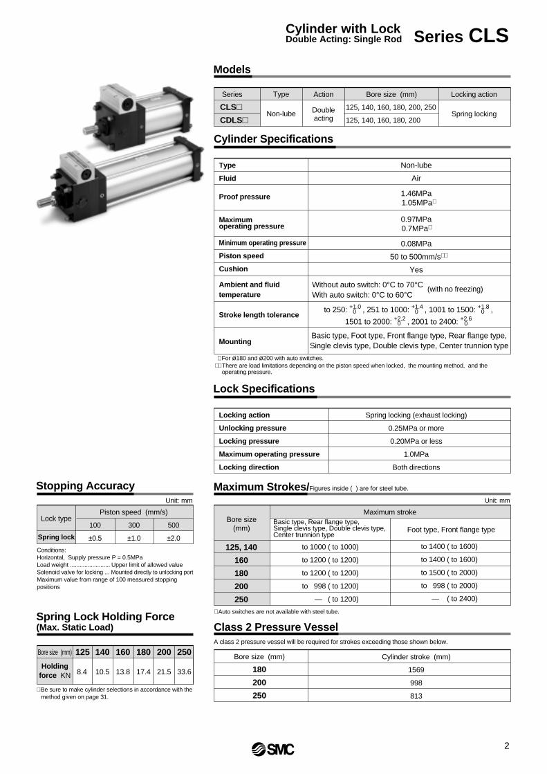
Type
Non-lube
Action
Doubleacting
Locking action
Spring locking
Bore size (mm)
Models
Type
Fluid
Proof pressure
Maximumoperating pressure
Minimum operating pressure
Piston speed
Cushion
Cylinder Specifications
Non-lube
Air
1.46MPa 1.05MPa∗
0.97MPa0.7MPa∗
0.08MPa
50 to 500mm/s∗∗
Yes
to 250: +1.0 , 251 to 1000: +1.4 , 1001 to 1500: +1.8 ,
1501 to 2000: +2.2 , 2001 to 2400: +2.6 0 0 0
0 0
Without auto switch: 0°C to 70°CWith auto switch: 0°C to 60°C
Basic type, Foot type, Front flange type, Rear flange type,Single clevis type, Double clevis type, Center trunnion type
Ambient and fluidtemperature
Stroke length tolerance
Mounting
Locking action
Unlocking pressure
Locking pressure
Maximum operating pressure
Locking direction
Lock Specifications
Spring locking (exhaust locking)
0.25MPa or more
0.20MPa or less
1.0MPa
Both directions
Bore size(mm)
125, 140
160
180
200
250
Maximum Strokes/Figures inside ( ) are for steel tube.
Maximum stroke
to 1000 ( to 1000)
to 1200 ( to 1200)
to 1200 ( to 1200)
to 998 ( to 1200)
— ( to 1200)
Lock type
Spring lock
Stopping Accuracy
Piston speed (mm/s)
100
±0.5
300
±1.0
500
±2.0
Bore size (mm)
Holdingforce KN
Spring Lock Holding Force(Max. Static Load)
8.4
125
10.5
140
13.8
160
17.4
180
21.5
200
33.6
250
(with no freezing)
Unit: mm
Bore size (mm)
180
200
250
Class 2 Pressure VesselA class 2 pressure vessel will be required for strokes exceeding those shown below.
Cylinder stroke (mm)
1569
998
813
Series
CLS
CDLS
Unit: mm
to 1400 ( to 1600)
to 1400 ( to 1600)
to 1500 ( to 2000)
to 998 ( to 2000)
— ( to 2400)
Foot type, Front flange type
∗ Auto switches are not available with steel tube.
125, 140, 160, 180, 200, 250
125, 140, 160, 180, 200
∗ For ø180 and ø200 with auto switches.∗∗ There are load limitations depending on the piston speed when locked, the mounting method, and the
operating pressure.
Conditions:Horizontal, Supply pressure P = 0.5MPaLoad weight ......................... Upper limit of allowed valueSolenoid valve for locking ... Mounted directly to unlocking port Maximum value from range of 100 measured stopping positions
∗ Be sure to make cylinder selections in accordance with the method given on page 31.
Basic type, Rear flange type,Single clevis type, Double clevis type, Center trunnion type
2
Cylinder with LockDouble Acting: Single Rod Series CLS

Mounting Brackets/Part Numbers
Bore size (mm) Foot type Note 1)
Flange type Note 2)
Single clevis type
Double clevis Note 3)
125
CS1-L12
CS1-F12
CS1-C12
CS1-D12
140
CS1-L14
CS1-F14
CS1-C14
CS1-D14
160
CS1-L16
CS1-F16
CS1-C16
CS1-D16
180
CS1-L18
CS1-F18
CS1-C18
CS1-D18
200
CS1-L20
CS1-F20
CS1-C20
CS1-D20
250
CS1-L25
CS1-F25
CS1-C25
CS1-D25
Note 1) When ordering foot brackets, 2pcs. should be ordered for each cylinder.Note 2) ø125 to ø250 front flange types use series CS1 long stroke flanges.Note 3) A clevis pin, flat washer and cotter pin are packed with the double clevis type.
Rod Boot Materials
Symbol
J
K
Material
Nylon tarpaulin
Heat resistant tarpaulin
Max. ambient temperature
60°C
100°C∗
∗ Maximum ambient temperature for the rod boot itself.
Accessories
Mounting brackets
—
Standard equipment
Options
Clevis pin
Rod end nut
Single knuckle joint
Double knuckle joint (with pin)
With rod boot
—
—
—
—
—
Basic type Foot typeFront flange
typeRear flange
typeSingle clevis
typeDouble clevis
typeCenter trunnion
type
Weight Table/Numbers inside ( ) are for steel tube
(kg)
Bore size (mm)
Additional weight per 100mm of stroke
Basic type
Foot type
Flange type
Single clevis type
Single knuckle
Double knuckle (with pin)
Rod end nut
125
23.49 (24.96)
Construction Principle
Basic weight .................... 30.82 (foot type, ø140)Additional weight ............. 1.96/100mm strokeCylinder stroke ................ 100mm stroke30.82 + 1.96 x 100/100 = 32.78kg
Spring locking (exhaust locking)The brake piston actuated by the force of the spring turns the eccentric cam shaft via the brake lever. This turning force distorts the shoe holder due to the wedge effect of the cam, acting on the brake shoe and locking the piston rod by tightening on it with a large force.Unlocking occurs when air pressure is supplied to the unlocking port, causing the brake piston to counteract the force of the spring and push the brake lever back. This removes the force which is distorting the shoe holder and unlocks the piston rod.
Locked condition(when air is exhausted)
Unlocked condition(when air is supplied)
140 1609.40Lock unit weight
Auto Switch Weight Table(kg)
Autoswitchtype
So
lid s
tate
switc
h
D-A5/A6D-A59W
ø125
0.038
0.094
0.156
0.156
0.038
0.094
0.156
ø140
0.038
0.094
0.160
0.160
0.038
0.094
0.160
ø160
0.041
0.097
0.165
0.165
0.041
0.097
0.165
ø180
0.045
0.101
0.168
0.168
0.045
0.101
0.168
ø200
0.047
0.103
0.173
0.173
0.047
0.103
0.173
Leadwire
length
Switchunit
Switch + switch mounting bracket
D-A3
D-A4
D-A9
D-F5/J5D-F59W/J59W
D-F9
D-G39/K39
0.5m
3 m
—
—
0.5m
3 m
0.5m
3 m
—
0.5m
3 m
0.024
0.080
0.116
0.114
0.008
0.041
0.024
0.080
0.116
0.007
0.037
Ree
dsw
itch
Model
Trunnion type
Double clevis type(includes clevis pin
& cotter pin)
Spring forceBrake lever
Brake pistonLocking spring Air pressure
Brake shoe holder
Eccentric cam shaft
28.30 (30.11)
11.37
40.87 (43.08)
16.93
25.12 (26.59)
30.82 (32.63)
43.67 (45.88)
26.17 (27.64)
33.30 (35.11)
47.26 (49.47)
26.56 (28.03)
32.59 (34.40)
46.36 (48.57)
27.02 (28.49)
33.34 (35.15)
47.21 (49.42)
27.62 (29.09)
34.03 (35.84)
48.27 (50.48)
1.77 (2.66)
0.91
1.37
0.16
1.16
1.81
0.16
1.56
2.48
0.23
1.96 (3.01)
2.39 (3.58)
180
57.30 (63.91)
200 25026.20
75.46 (82.01)
36.4
— (138.94)
61.70
61.50 (68.11)
80.34 (86.89)
— (148.44)
67.13 (73.74)
87.37 (93.92)
— (160.78)
65.69 (72.30)
85.36 (91.91)
— (157.33)
67.37 (73.98)
87.39 (93.94)
— (160.52)
68.46 (75.07)
89.45 (96.00)
— (166.78)
2.85 (4.95)
3.07
4.74
0.33
2.90
4.59
0.56
5.38
9.22
1.01
3.42 (5.75)
— (9.08)
Calculation (Ex.) CLSL140-100
Bas
ic w
eigh
tAc
cess
orie
s
∗ Refer to the accessory models and dimensions on page 12.
Series CLS
3

Construction
No.
1
2
3
45678910111213141516
17
1819202122232425262728293031323334353637383940
41
Description Material Note
Parts list
Replacement parts/Seal kits
Cover A
Cover B
Thrust washer A
Thrust washer BBrake shoe holder ABrake shoeEccentric cam shaftBrake leverWasherNeedle bearingNeedle bearingStopperAdjustment screwConical spring washerU nutCover
Cover holding screw
Cover holding boltBrake tubeBrake piston ABrake piston BBottom plateSpring collarBrake springBumper BMagnetSnap ringMarkerTrim plateKeyBrake tube holding boltManual release boltPlug with breathing holeRetaining plate BRetaining plate holding boltUnit holding tie-rodWing nutConical spring washerRod coverHead cover
Cylinder tube
Aluminum alloy
Aluminum alloy
Carbon steel
Carbon steelChromium molybdenum steel
Special friction materialSpecial steel
Chromium molybdenum steelCarbon steel
––
Special steelChromium molybdenum steel
Spring steelCarbon steelSteel plate
Carbon steel
Chromium molybdenum steelAluminum alloyCarbon steel
Aluminum alloyAluminum alloyAluminum alloy
Steel wirePolyurethane rubber
–Carbon tool steel
ResinResin
Carbon steelChromium molybdenum steelChromium molybdenum steel
–Bronze casting
Chromium molybdenum steelCarbon steelCarbon steelSpring steel
Rolled steel plateRolled steel plateAluminum alloy
Carbon steel pipe
Black hard anodized (ø125, ø140, ø160) Hard anodized & coated (ø180, ø200, ø250)
Black hard anodized (ø125, ø140, ø160) Hard anodized & coated (ø180, ø200, ø250) Electroless nickel plated (ø125, ø140, ø160)
Special treatment (ø180, ø200, ø250) Electroless nickel plated (ø125, ø140, ø160)
Special treatment
Zinc chromatedZinc chromated
Electroless nickel platedZinc chromatedZinc chromatedZinc chromated
Black zinc chromated
Nickel platedClear hard anodized
TufftrideChromated
Black anodizedBlack anodizedZinc chromated
(With switch for lock unit)Phosphate coated
White
Nickel platedNickel plated
Black zinc chromated
Nickel platedChromated
Nickel platedNickel platedBlack coatedBlack coated
Hard anodized (ø125 to ø200)Hard chrome plated (ø125 to ø250)
Bore size (mm)
125140160180200250
Order No.
CLS125-PS
CLS140-PS
CLS160-PS
CLS180-PS
CLS200-PS
CLS250-PS
Contents
No.
42
43444546474849505152535455565758596061626364656667686970
Description Material Note
Parts list
Piston
Piston rodRetaining plateBushingValve guideTie-rodTie-rod nutSpring washerRetaining plate boltSpring washerCushion ring ACushion ring BCushion valveTie-rod reinforcement ringWear ringMagnetPiston sealTube gasketWiper ringCushion sealRod sealPiston sealValve sealTube gasketPiston gasketRetaining plate gasketGuide gasketCoil scraperCoil scraper holder
Aluminum alloy castingCast iron
Carbon steelCast iron
Lead bronze castingBrass
Carbon steelRolled steel plate
Steel wireChromium molybdenum steel
Steel wireRolled steelRolled steelRolled steelRolled steel
Resin–
NBRNBRNBRNBRNBRNBRNBRNBRNBRNBRNBR
Phosphor bronzeAluminum alloy
In case of aluminum tubeIn case of iron tube
Hard chrome platedBlack coated (ø125, ø140, ø160)
ChromatedBlack zinc chromatedBlack zinc chromatedBlack zinc chromatedBlack zinc chromated
Zinc chromatedZinc chromated
Electroless nickel platedBlack coated (long stroke)In case of aluminum tubeFor built-in magnet type
(ø180, ø200, ø250) Black anodized (ø180, ø200, ø250)
A set of above Nos.60, 62, 63, 64, 65 & 67
ø180, ø200, ø250
∗ Since the lock section for Series CLS is normally replaced as a unit, replacement seal kits are for the cylinder section only.
∗∗ Seal kits are sets consisting of items 60, 62, 63, 64, 65 and 67, which can be ordered using the order number for each cylinder bore size.
Cylinder with LockDouble Acting: Single Rod Series CLS
4

Basic type/(B)
Dimensions
With rod boot For ø180, ø200, ø250
F
FA
15
MM
Width across flats KA
øD
øe
øE
A
øE
AL
A K
H
f
BY
BB
BC
BA
M GA GA
S + Stroke
ZZ + Stroke
ZZ1 + l + Stroke
N N
BW
BZ
BV
M
2-Rc PCylinder port
l
h + l
T
4-J
GC
GB
W
BZ
CB
Plug with breathing hole
4-MAEffective thread depth MB(for holding eyebolt)
Rc BPUnlocking port(unlocked whenpressurized)
øV
MO
DE
L S
MC
FR
EE
LOC
K
CLS
125
CH
EC
K
Cyl
inde
r W
ith$
Lock
ing
Mec
hani
sm
Bore size(mm)
Strokerange(mm)
125140160180200250
to 1000to 1000to 1200to 1200to 1200to 1200
A
505056636371
(mm)
AL
474753606067
B
145161182204226277
BA
757895
106124152
118131155
BB
1818233640.558
BC
—
35—
—
—
BD
—
3046—
—
—
BE BG
—
—
—
162135
BV
—
—
—
5 5.56
BW
—
—
—
303442
MB
—
—
—
253141
BY
110110132167187237
BZ
136146169195216261.5
BP
1/41/41/43/83/81/2
C
115128144162182225
D
363640455060
E
909090
115115140
EA
595959707486
F
434343484860
FA
141414171720
GA
161618.518.518.523
GB
107114130149165200
H
110110120135135160
K
151517202025
KA
313136414656
N
353539393949
M
272730.5353541.5
J
M14 x 1.5M14 x 1.5M16 x 1.5M18 x 1.5M20 x 1.5M24 x 1.5
MM
M30 x 1.5M30 x 1.5M36 x 1.5M40 x 1.5M45 x 1.5M56 x 2
MA
—
—
—
M12 x 1.75 M16 x 2 M20 x 2.5
GC
5864748697
117
Bore size(mm)
Strokerange(mm)
125140160180200250
e
7575758590
105
(mm)With rod boot
f
404040454555
h
133133141153153176
30 to 100030 to 100030 to 120030 to 120030 to 120030 to 1200
l
0.2 stroke
0.2 stroke
0.2 stroke
0.2 stroke
0.2 stroke
0.17 stroke
ZZ1
368368409.5466486595.5
Bore size(mm)
Strokerange(mm)
125140160180200
S
9898
106115120
(mm)With auto switch
ZZ
Withoutrod boot
345345388.5452477
ZZ1
Withrod boot
368368409.5470495
to 1000to 1000to 1200to 1200to 998
Bore size(mm)
125140160180200250
(mm)
BD
BG BE
—
—
—
P
1/21/23/43/43/41
S
9898
106111111141
T
555—
—
—
V
303030—
—
—
ZZ
345345388.5448468579.5
W
—
89—
—
—
Series CLS
5

Axial foot type/(L)
Bore size(mm)
Strokerange(mm)
125140160180200250
to 1400 to 1400 to 1400 to 1800 to 1800 to 2000
Long stroke range(mm)
1401 to 16001401 to 16001401 to 16001801 to 20001801 to 20002001 to 2400
A
505056636371
(mm)
AL
474753606067
B
145161182204226277
BA
757895
106124152
BB
1818233640.558
BC
—
35—
—
—
BV
—
—
—
5 5.56
BW
—
—
—
303442
BY
110110132167187237
BZ
136146169195216261.5
BP
1/41/41/43/83/81/2
C
115128144162182225
D
363640455060
E
909090
115115140
EA
595959707486
F
434343484860
FA
141414171720
GA
161618.518.518.523
GB
107114130147163.5197
H
110110120135135160
K
151517202025
KA
313136414656
LD
191919242429
LH
85100106125132160
LS
298298338398418538
LT
899
101012
LX
100112118132150180
M
272730.5353541.5
LY
221246275320340421.5
J
M14 x 1.5M14 x 1.5M16 x 1.5M18 x 1.5M20 x 1.5M24 x 1.5
GC
5864748697
119
Bore size(mm)
125140160180200250
RT
363645454555
(mm)
RY
164184204228257325
M30 x 1.5M30 x 1.5M36 x 1.5M40 x 1.5M45 x 1.5M56 x 2
MM N
353539393949
P
1/21/23/43/43/41
S
9898
106111111141
T
555—
—
—
303030—
—
—
V W
—
89—
—
—
X
454550606080
203025303040
Y ZZ
383393433503523658
With rod boot For ø180, ø200, ø250
15
ZZ1 + l + Stroke
l
h + l
F
MM
Width acrossflats KA
øD
øe
øE
A
øE
AL M
A K
H
Y X N RT YXN
BW
BV
BZ
LX
GC
LT
W
R
Y
4-øLD
BB BA
GA M2-Rc PCylinder port
BY
BC
S + Stroke
LS + Stroke
For long strokes(tie-rod reinforcement ring)
ZZ + Stroke
Rc BPUnlocking port(unlocked whenpressurized)
Plug withbreathing hole
4-J
CB
GB B
ZL
YL
H
GA
f
SM
CC
LS12
5M
OD
EL
FR
EE
LOC
KC
HE
CK
Cyl
inde
r W
ith$
Lock
ing
Mec
hani
sm
øV
T
Bore size(mm)
Strokerange(mm)
125140160180200250
e
7575758590
105
(mm)With rod boot
f
404040454555
h
133133141153153176
30 to 140030 to 140030 to 140030 to180030 to 180030 to 2000
l
0.2 stroke
0.2 stroke
0.2 stroke
0.2 stroke
0.2 stroke
0.17 stroke
ZZ1
406416454521541674
Bore size(mm)
Strokerange(mm)
125140160180200
S
9898
106115120
LS
298298338402427
(mm)With auto switch
ZZ
Withoutrod boot
383393433507532
ZZ1
Withrod boot
406416454525550
to 1400to 1400to 1400to 1500to 998
FA
BD
BG BE
4-MAEffective thread depth MB(for holding eyebolt)
BD
—
3046—
—
—
BE
—
—
—
162135
118131155
BG
—
—
—
MB
—
—
—
253141
MA
—
—
—
M12 x 1.75 M16 x 2 M20 x 2.5
6
Cylinder with LockDouble Acting: Single Rod Series CLS
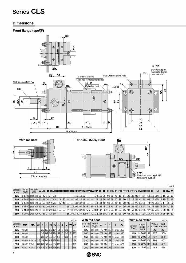
Front flange type/(F)
Dimensions
With rod boot For ø180, ø200, ø250
15
ZZ1 + l + Stroke
l
h + l
MM
Width across flats KA
øD
øe
øE
A
øE
F
AL FT
A K
H
f
BY
RT
S + Stroke
ZZ + Stroke
N N
BW
BZ
BV
M
R
Y
BB BA
GAM
For long strokes(tie-rod reinforcement ring)
2-Rc PCylinder port
GA
GB
BF
FY
BZ
GCPlug with breathing hole
4-J4-øFD
FXFZ
CB
Rc BPUnlocking port(unlocked whenpressurized)
W
CLS
125
MO
DE
L S
MC
FR
EE
LOC
KC
HE
CK
Cyl
inde
r W
ith$
Lock
ing
Mec
hani
sm
BC
øV
T
Bore size(mm)
Strokerange(mm)
125140160180200250
e
7575758590
105
(mm)With rod boot
f
404040454555
h
133133141153153176
30 to 1400
30 to 1400
30 to 1400
30 to 1800
30 to 1800
30 to 2000
l
0.2 stroke
0.2 stroke
0.2 stroke
0.2 stroke
0.2 stroke
0.17 stroke
ZZ1
360360401457477584
Bore size(mm)
Strokerange(mm)
125140160180200
S
9898
106115120
(mm)With auto switch
ZZ
Withoutrod boot
337337380443468
ZZ1
Withrod boot
360360401461486
to 1400 to 1400 to 1400 to 1500 to 998
BD
4-MAEffective thread depth MB(for holding eyebolt)
BG BE
Bore size(mm)
Strokerange(mm)
125140160180200250
to 1400to 1400to 1400to 1800to 1800to 2000
Long stroke range(mm)
1401 to 1600
1401 to 1600
1401 to 1600
1801 to 2000
1801 to 2000
2001 to 2400
A
505056636371
(mm)
AL
474753606067
B
145161182204226277
BA
757895
106124152
BB
1818233640.558
BC
—
35—
—
—
BV
—
—
—
5 5.56
BW
—
—
—
303442
BY
145160180200225275
110110132167182237
BZ
136146169195216261.5
BP
1/41/41/43/83/81/2
C
115128144162182225
D
363640455060
E
909090
115115140
EA
595959707486
F
434343484860
191919242429
FD
142020252530
FT
161618.518.518.523
FX
107114130147163.5197
FZ
110110120135135160
190212236265280355
100112118132150180
230255275320335420
GB
151517202025
GC
191922262630
313136414656
H J K KA MGA
M14 x 1.5M14 x 1.5M16 x 1.5M18 x 1.5M20 x 1.5M24 x 1.5
FY
5864748697
119
BD
—
3046—
—
—
BE
—
—
—
162135
118131155
BG BF
—
—
—
Bore size(mm)
125140160180200250
RT
363645454555
(mm)
RY
164184204228257325
M30 x 1.5
M30 x 1.5
M36 x 1.5
M40 x 1.5
M45 x 1.5
M56 x 2
MM N
353539393949
P
1/21/23/43/43/41
S
9898
106111111141
T
555—
—
—
303030—
—
—
V W
—
89—
—
—
ZZ
337337380439459568
MB
—
—
—
253141
MA
—
—
—
M12 x 1.75
M16 x 2
M20 x 2.5
Series CLS
7

Rear flange type/ (G)
With rod boot For ø180, ø200, ø250
15
ZZ1 + l + Stroke
l
h + l
MM
Width across flats KA
øD
øe
øE
Aø
E
BB
M
BA
F
FAAL
A K
H BY
f
S + Stroke
ZZ + Stroke
GA GA2-Rc PCylinder port
N
BW
BV
BZ
N
FTFXFZ
CB
BF
FY
GB B
Z
4-øFD
4-J
Plug with breathing hole
Rc BPUnlocking port(unlocked whenpressurized)GC
MO
DE
L S
MC
FR
EE
LOC
K
CLS
125
CH
EC
K
Cyl
inde
r W
ith$
Lock
ing
Mec
hani
sm
BC
øV
T
Bore size(mm)
Strokerange(mm)
125140160180200250
to 1000to 1000to 1200to 1200to 1200to 1200
A
505056636371
(mm)
AL
474753606067
B
145161182204226277
BF
145160180200225275
BA
757895
106124152
BB
1818233640.558
BC
—
35—
—
—
BV
—
—
—
5 5.56
BW
—
—
—
303442
BY
110110132167187237
BZ
136146169195216261.5
BP
1/41/41/43/83/81/2
C
115128144162182225
D
363640455060
E
909090
115115140
EA
595959707486
F
434343484860
FA
141414171720
FD
191919242429
FT
142020252530
FX
190212236265280355
FY
100112118132150180
FZ
230255275320335420
GA
161618.518.518.523
GB
107114130147163.5197
H
110110120135135160
K
151517202025
KA
313136414656
M
191922262630
J
M14 x 1.5M14 x 1.5M16 x 1.5M18 x 1.5M20 x 1.5M24 x 1.5
GC
5864748697
119
Bore size(mm)
125140160180200250
(mm)
N
353539393949
P
1/21/23/43/43/41
S
9898
106111111141
T
555—
—
—
303030—
—
—
V W
—
89—
—
—
ZZ
332338378438458568
Bore size(mm)
Strokerange(mm)
125140160180200250
e
7575758590
105
(mm)With rod boot
f
404040454555
h
133133141153153176
30 to 100030 to 100030 to 120030 to 120030 to 120030 to 1200
l
0.2 stroke
0.2 stroke
0.2 stroke
0.2 stroke
0.2 stroke
0.17 stroke
ZZ1
355361399456476584
Bore size(mm)
Strokerange(mm)
125140160180200
S
9898
106115120
(mm)With auto switch
ZZ
Withoutrod boot
332338378442467
ZZ1
Withrod boot
355361399460485
to 1000to 1000to 1200to 1200to 998
W
118131155
BD
—
3046—
—
—
BE BG
—
—
—
162135
MB
—
—
—
253141
MM
M30 x 1.5M30 x 1.5M36 x 1.5M40 x 1.5M45 x 1.5M56 x 2
MA
—
—
—
M12 x 1.75 M16 x 2 M20 x 2.5
BD
4-MAEffective thread depth MB(for holding eyebolt)
BG BE
—
—
—
8
Cylinder with LockDouble Acting: Single Rod Series CLS

Single Clevis Type (C)
Dimensions
With rod boot For ø180, ø200, ø250
øD
øE
A
øE
F
FAAL
A K
H BY
f
MM
Width across flats KA
BB
M
BA
BC
GA GA
N U
L
RR
BW
BZ
BV
GC
CTN
S + Stroke
Z + Stroke
ZZ + Stroke
2-Rc PCylinder port
øCD hole H10Shaft d9
Plug with breathing hole
4-J
GB B
Z
Rc BPUnlocking port(unlocked whenpressurized)
CXCB
15
Z1 + l + Stroke
ZZ1 + l + Stroke
l
h + l
øV W
T
CLS
125
MO
DE
L S
MC
FR
EE
LOC
KC
HE
CK
Cyl
inde
r W
ith$
Lock
ing
Mec
hani
sm
øe
Bore size(mm)
Strokerange(mm)
125140160180200250
to 1000 to 1000 to 1200 to 1200 to 1200 to 1200
A
505056636371
(mm)
AL
474753606067
B
145161182204226277
BA
757895
106124152
BB
1818233640.558
BC
—
35—
—
—
BV
—
—
—
5 5.56
BW
—
—
—
303442
BY
110110132167187237
BZ
136146169195216261.5
BP
1/41/41/43/83/81/2
CDH10C
115128144162182225
D
363640455060
CXCT
171720232530
E
909090
115115140
EA
595959707486
F
434343484860
FA
141414171720
GA
161618.518.518.523
GB
107114130147163.5197
H
110110120135135160
K
151517202025
KA
313136414656
L
6575809090
110
M
191922262630
J
M14 x 1.5M14 x 1.5M16 x 1.5M18 x 1.5M20 x 1.5M24 x 1.5
GC
5864748697
119
Bore size(mm)
125140160180200250
RR
293236444455
(mm)
N
353539393949
P
1/21/23/43/43/41
S
9898
106111111141
T
555—
—
—
303030—
—
—
V W
—
89—
—
—
U
354045505065
383393438503523648
Z ZZ
412425474547567703
Bore size(mm)
Strokerange(mm)
125140160180200250
e
7575758590
105
(mm)With rod boot
f
404040454555
h
133133141153153176
30 to 1000
30 to 1000
30 to 1200
30 to 1200
30 to 1200
30 to 1200
l
0.2 stroke
0.2 stroke
0.2 stroke
0.2 stroke
0.2 stroke
0.17 stroke
ZZ1
435448495565585719
Z1
406416459521541664
Bore size(mm)
Strokerange(mm)
125140160180200
S
9898
106115120
(mm)With auto switch
ZZ412425474551576
Z383393438507532
ZZ1
435448495569594
Z1
406416459525550
to 1000 to 1000 to 1200 to 1200 to 998
252832404050
+0.0840
+0.0840
+0.1000
+0.1000
+0.1000
+0.1000
323640505063
–0.1–0.3–0.1–0.3–0.1–0.3–0.1–0.3–0.1–0.3–0.1–0.3
118131155
BD
—
3046—
—
—
BE BG
—
—
—
162135
MB
—
—
—
253141
MM
M30 x 1.5M30 x 1.5M36 x 1.5M40 x 1.5M45 x 1.5M56 x 2
MA
—
—
—
M12 x 1.75 M16 x 2 M20 x 2.5
BD
4-MAEffective thread depth MB(for holding eyebolt)
BG BE
Withoutrod boot
Withrod boot
—
—
—
Series CLS
9

Double Clevis Type/(D)
With rod boot For ø180, ø200, ø250
15
Z1 + l + Stroke
ZZ1 + l++ Stroke
l
h + l
f
øD
øE
A
øE
F
FAAL
A K
H BY
MM
Width across flats KA
BB
M
BA
BC
GA GA
N U
L
RR
BV
BZ
BW
CTN
S + Stroke
Z + Stroke
ZZ + Stroke
2-Rc PCylinder port øCD hole H10
Shaft d9
GC
Plug with breathing hole
T
4-J GB B
Z
Rc BPUnlocking port(unlocked whenpressurized)
CX
CZCB
øV W
CLS
125
MO
DE
L S
MC
FR
EE
LOC
KC
HE
CK
Cyl
inde
r W
ith$
Lock
ing
Mec
hani
sm
øe
Bore size(mm)
Strokerange(mm)
125140160180200250
to 1000
to 1000
to 1200
to 1200
to 1200
to 1200
A
505056636371
(mm)
AL
474753606067
B
145161182204226277
BA
757895
106124152
BB
1818233640.558
BC
—
35—
—
—
BV
—
—
—
5 5.56
BW
—
—
—
303442
BY
110110132167187237
BZ
136146169195216261.5
BP
1/41/41/43/83/81/2
C CDH10
115128144162182225
D
363640455060
CT CX
171720232530
E
909090
115115140
EA
595959707486
F
434343484860
FA
141414171720
GA
161618.518.518.523
GB
107114130147163.5197
H
110110120135135160
K
151517202025
KA
313136414656
L
6575809090
110
J
M14 x 1.5M14 x 1.5M16 x 1.5M18 x 1.5M20 x 1.5M24 x 1.5
GC
5864748697
119
Bore size(mm)
125140160180200250
RR
293236444455
(mm)
N
353539393949
MA
M30 x 1.5M30 x 1.5M36 x 1.5M40 x 1.5M45 x 1.5M56 x 2
P
1/21/23/43/43/41
S
9898
106111111141
T
555—
—
—
303030—
—
—
V W
—
89—
—
—
U
354045505065
383393438503523648
Z ZZ
412425474547567703
125140160180200250
e
7575758590
105
(mm)
f
404040454555
h
133133141153153176
30 to 1000
30 to 1000
30 to 1200
30 to 1200
30 to 1200
30 to 1200
l
0.2 stroke
0.2 stroke
0.2 stroke
0.2 stroke
0.2 stroke
0.17 stroke
ZZ1
435448495565585719
Bore size(mm)
Strokerange(mm)
125140160180200
S
9898
106115120
(mm)
ZZ412425474551576
Z383393438507532
ZZ1
435448495569594
Z1
406416459525550
to 1000 to 1000 to 1200 to 1200 to 998
252832404050
+0.084 0 +0.084 0+0.100 0+0.100 0+0.100 0+0.100 0
323640505063
+0.3+0.1+0.3+0.1+0.3+0.1+0.3+0.1+0.3+0.1+0.3+0.1
CZ
647280
100100126
0–0.20
–0.20
–0.2–0.1–0.3–0.1–0.3–0.1–0.3
BD
BG BE
4-MAEffective thread depth MB(for holding eyebolt)
118131155
BD
—
3046—
—
—
BE BG
—
—
—
162135
M
191922262630
MB
—
—
—
253141
MM
—
—
—
M12 x 1.75 M16 x 2 M20 x 2.5
Z1
406416459521541664
Bore size(mm)
Strokerange(mm)
With rod boot With auto switchWithoutrod boot
Withrod boot
—
—
—
10
Cylinder with LockDouble Acting: Single Rod Series CLS

Center Trunnion type/(T)
Dimensions
With rod boot For ø180, ø200, ø250
15
Z1 + l + 1/2 Stroke
ZZ1 + l + Stroke
l
h + l
Z + 1/2 Stroke
øD
øE
A
øE
MM
S + Stroke
ZZ + Stroke
BB BA
M
F
FAAL
A K
H BY
N N
BW
BV
BZ
MTT
GA GA2-Rc PCylinder port
Plug with breathing hole
GC
Rc 1/4BPUnlocking port(unlocked whenpressurized)
GB
R
BZ
TY
øT
De8
W
TXTZ
CB
4-J
f
CLS
125
MO
DE
L S
MC
FR
EE
LOC
KC
HE
CK
Cyl
inde
r W
ith$
Lock
ing
Mec
hani
sm
BC
øV
T
øe
125140160180200250
25 to 100030 to 100035 to 120030 to 120030 to 120030 to 1200
A
505056636371
(mm)
AL
474753606067
B
145161182204226277
BA
757895
106124152
BB
1818233640.558
BC
—
35—
—
—
BV
—
—
—
5 5.56
BW
—
—
—
303442
BY
110110132167187237
BZ
136146169195216261.5
BP
1/41/41/43/83/81/2
C
115128144162182225
D
363640455060
E
909090
115115140
EA
595959707486
F
434343484860
FA
141414171720
GA
161618.518.518.523
GB
107114130147163.5197
H
110110120135135160
P
1/21/23/43/43/41
N
353539393949
K
151517202025
KA
313136414656
M
191922262630
J
M14 x 1.5M14 x 1.5M16 x 1.5M18 x 1.5M20 x 1.5M24 x 1.5
MM
M30 x 1.5M30 x 1.5M36 x 1.5M40 x 1.5M45 x 1.5M56 x 2
GC
5864748697
119
125140160180200250
(mm)
TDe8 TT
505560595969
TZ
234262292326355447
TY
164184204228257325
TX
170190212236265335
303030—
—
—
V W
—
89—
—
—
ZZ
337337380439459568
Z
269269305357.5377.5467.5
125140160180200250
e
7575758590
105
(mm)With rod boot
f
404040454555
h
133133141153153176
30 to 100030 to 100030 to 120030 to 120030 to 120030 to 1200
l
0.2 stroke
0.2 stroke
0.2 stroke
0.2 stroke
0.2 stroke
0.17 stroke
ZZ1
360360401457477584
Z1
292292326375.5395.5483.5
125140160180200
S
9898
106115120
(mm)
ZZ337337380443468
Z269269305361.5386.5
ZZ1
360360401461486
Z1
292292326379.5404.5
to 1000 to 1000 to 1200 to 1200 to 998
323640
–0.050–0.089–0.050–0.089–0.050–0.089
454556
–0.050–0.089–0.050–0.089–0.060–0.106
118131155
BD
—
3046—
—
—
BGBE
—
—
—
162135
MB
—
—
—
253141
MA
—
—
—
M12 x 1.75 M16 x 2 M20 x 2.5
R
11.51.5223
S
9898
106111111141
T
555—
—
—
BD
4-MA
BG BE
Effective thread depth MB(for holding eyebolt)
With auto switch
Bore size(mm)
Strokerange(mm)
Bore size(mm)
Strokerange(mm) Bore size
(mm)Strokerange(mm)
Bore size(mm)
Withoutrod boot
Withrod boot
Width across flats KA
Series CLS
11

Model
Y-12Y-14Y-16Y-18Y-20Y-25
(mm)
125140160180200250
E1 L1 MM NZ RR1 U1
M30 x 1.5
M30 x 1.5
M36 x 1.5
M40 x 1.5
M45 x 1.5
M56 x 2
64–0.1–0.3
72–0.1–0.3
80–0.1–0.3
100–0.1–0.3
100–0.1–0.3
126–0.1–0.3
46
48
55
70
70
86
A1
8
8
8
8
8
9
100
105
110
125
125
160
27
30
34
42.5
42.5
53
42
47
46
54
54
81
Clevis Pin/Knuckle Pin
Model
IY-12IY-14IY-16IY-18IY-25
(mm)
125140160
180, 200250
Dd9 L l
25–0.065–0.117
28–0.065–0.117
79.5
86.5
94.5
115
144
Cotter pin
32–0.080–0.142
40–0.080–0.142
50–0.080–0.142
69.5
76.5
84.5
105
132
ø4 x 40l
ø4 x 40l
ø4 x 40l
ø4 x 55l
ø5 x 65l
d(drill through)
4
4
4
4
5
Model
NT-12NT-16NT-18NT-20NT-25
(mm)
125, 140160180200250
d H
M30 x 1.5
M36 x 1.5
M40 x 1.5
M45 x 1.5
M56 x 2
18
21
23
27
34
B
46
55
60
70
85
C
53.1
63.5
69.3
80.8
98.1
D
44
53
57
67
82
RR1
l
L5 5
øD
d9
2-ød
NX
32+0.3+0.1
36+0.3+0.1
40+0.3+0.1
50+0.3+0.1
50+0.3+0.1
63+0.3+0.1
NDH10
I Type Single Knuckle Joint
Model
I-12I-14I-16I-18I-20I-25
(mm)
125140160180200250
A2 E1 MM NX RR1 U1
M30 x 1.5
M30 x 1.5
M36 x 1.5
M40 x 1.5
M45 x 1.5
M56 x 2
54
54
60
67
67
75.5
46
48
55
70
70
86
A1
8
8
8
8
8
9
27
30
34
42.5
42.5
53
33
39
39
44
44
66
NDH10
25+0.0840
28+0.0840
32+0.1 0
40+0.10
40+0.10
50+0.10
Rod End Nut
L1
100
105
110
125
125
160
25+0.0840
28+0.0840
32+0.10
40+0.10
40+0.1 0
50+0.10
32–0.1–0.3
36–0.1–0.3
40–0.1–0.3
50–0.1–0.3
50–0.1–0.3
63–0.1–0.3
MM A1
U1
L1
NX
NZ
øNDHole H10Shaft d9
øE
1
RR1
MMA2
A1
L1U1
NX
øNDH10
øE
1
30°
H B
d
D C
Y Type Double Knuckle Joint ∗ Pins and snap rings for double clevis and double knuckle joint are included when shipped.
Applicable boresize (mm)
Material: Cast iron
Material: Carbon steel
Applicable bore size (mm)
Applicable boresize (mm)
Material: Cast iron
Applicable boresize (mm)
Material: Rolled steel
Series CLSAccessory Dimensions
12

Single/Double Knuckle Joint Mounting
HA
L1
H1
125140160180200250
I type single knuckle
I-12
I-14
I-16
I-18
I-20
I-25
Y type double knuckle
Y-12
Y-14
Y-16
Y-18
Y-20
Y-25
H1
156.5
161.5
170.5
193.5
193.5
245.5
L1
100
105
110
125
125
160
H
110
110
120
135
135
160
A
50
50
56
63
63
71
Bore size (mm)
125140160180200250
H125
125
140
155
160
195
A 65
65
76
83
88
106
3.5(mm)
SymbolBore size (mm)
Applicable knuckle joint part nos.
A, H dimensions when single/double knuckle joint and rod end nut are mounted together
∗ Single knuckle joint and double knuckle joint should be used separately.(Fasten by screwing completely into the rod end threads.)
∗ When using a single/double knuckle joint together with a rod end nut, the A and H dimensions should be extended.(For extension of the A and H dimensions, refer to the table above and specify the order made product –XAO.)
Series CLSAccessory Dimensions
13
D-A3D-A44D-A5/A6D-A59WD-A90∗D-A93∗D-G39/K39D-F5/J5D-F5NTLD-F5W/J59WD-F5BALD-F5FD-F9N∗D-F9P∗D-F9B∗
D-A53
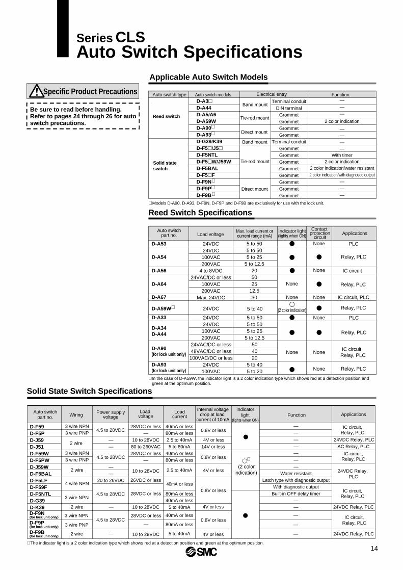
Solid State Switch Specifications
Auto switchpart no.
D-F59D-F5PD-J59D-J51D-F59WD-F5PWD-J59WD-F5BALD-F5LFD-F59FD-F5NTLD-G39D-K39
ApplicationsFunctionIndicator
light (lights when ON)
WiringInternal voltage
drop at load current of 10mA
Load voltage
Power supplyvoltage
D-A54
D-A56
D-A64
D-A67
D-A59W∗
D-A34D-A44
D-A90(for lock unit only)
D-A93(for lock unit only)
D-A33
5 to 505 to 505 to 25
5 to 12.5205025
12.530
5 to 40
5 to 505 to 505 to 25
5 to 12.5504020
5 to 405 to 20
None
None
(2 color indication)
None
None
None
None None
None
None
3 wire NPN3 wire PNP
3 wire NPN3 wire PNP
2 wire
4 wire NPN
2 wire
Loadcurrent
40mA or less80mA or less2.5 to 40mA5 to 80mA
40mA or less80mA or less
2.5 to 40mA
80mA or less40mA or less
5 to 40mA
40mA or less
80mA or less
5 to 40mA
———————
Water resistantLatch type with diagnostic output
With diagnostic outputBuilt-in OFF delay timer
——
0.8V or less
0.8V or less
0.8V or less
4V or less
4V or less
4V or less
0.8V or less4.5 to 28VDC
4.5 to 28VDC
20 to 26VDC
4.5 to 28VDC
4.5 to 28VDC
IC circuit,Relay, PLC
IC circuit,Relay, PLC
IC circuit,Relay, PLC
24VDC Relay, PLC
24VDC Relay, PLC
24VDC Relay, PLC
24VDC Relay, PLC
IC circuit,Relay, PLC
AC Relay, PLC
4V or less14V or less
28VDC or less—
10 to 28VDC80 to 260VAC28VDC or less
—
26VDC or less
28VDC or less
10 to 28VDC
10 to 28VDC
10 to 28VDC
∗ The indicator light is a 2 color indication type which shows red at a detection position and green at the optimum position.
∗ (2 color
indication)
D-F9N(for lock unit only)
D-F9P(for lock unit only)
D-F9B(for lock unit only)
3 wire NPN 28VDC or less
—
—
—
——
3 wire PNP
2 wire
∗ Models D-A90, D-A93, D-F9N, D-F9P and D-F9B are exclusively for use with the lock unit.
40mA or less
2 wire
3 wire NPN
——
——
—
Applicable Auto Switch Models
Auto switch type Auto switch models Electrical entry Function
Reed switch
Solid stateswitch
Band mount
Band mount
Direct mount
Direct mount
Tie-rod mount
Tie-rod mount
Terminal conduitDIN terminal
GrommetGrommetGrommetGrommet
Terminal conduitGrommetGrommetGrommetGrommetGrommetGrommetGrommetGrommet
———
2 color indication
————
With timer2 color indication
2 color indication/water resistant2 color indication/with diagnostic output
———
Specific Product Precautions
Be sure to read before handling. Refer to pages 24 through 26 for auto switch precautions.
Reed Switch Specifications
Auto switchpart no.
Max. load current orcurrent range (mA) Applications
Contact protection
circuitLoad voltage
Indicator light(lights when ON)
24VDC24VDC100VAC200VAC
4 to 8VDC24VAC/DC or less
100VAC200VAC
Max. 24VDC
24VDC
24VDC24VDC100VAC200VAC
24VAC/DC or less48VAC/DC or less100VAC/DC or less
24VDC100VAC
PLC
Relay, PLC
IC circuit
Relay, PLC
IC circuit, PLC
IC circuit, Relay, PLC
Relay, PLC
PLC
Relay, PLC
Relay, PLC
∗ In the case of D-A59W, the indicator light is a 2 color indication type which shows red at a detection position and green at the optimum position.
Series CLSAuto Switch Specifications
14

125
140
160
180
200
A
0
0
0
3.5
6
B
0
0
0
1.5
4
(mm)
D-A59W D-F5NTL
125
140
160
180
200
(mm)
D-A3D-G39D-K39
D-A44D-A5D-A6D-A59W
Hs
116
124
134.5
144
154
Hs
75.5
81
89
97.0
107.0
Ht
69.5
76.5
87.5
97.5
108.0
Hs
126
134
144.5
154
164
Hs
74.5
80
88
96
107.5
Ht
70
76.5
87.5
97.5
108.0
D-F5/J5/D-F5NTLD-F5W/J59WD-F5BAL/F5F
D-A5/A6D-A3D-A44D-G39D-K39
D-F5WD-J59WD-F5BALD-F5D-J5
D-F5D-J5D-F5WD-J59WD-F5BALD-F5FD-F5NTL
D-A5/A6D-A59W
D-A3D-G39/K39
D-A44
D-A5/A6/A59WF5/J5/F5NTLF5W/J59WF5BAL /F59F
D-A5, A6D-A59WD-F5, J5
ø125
125
ø140
135
ø160
135
125 140 200
D-F5W, J59WD-F5BALD-F59FD-F5NTL
D-A3D-G39D-K39
D-A44
25
25 + 55
n = 2, 4, 6, 8…
(n–2)2
35
35 + 55n = 2,4,6,8…
(n–2) 2
2pcs.
Different side
Same side
Different side
Same side
Different side
Same side
Different side
Same side
"n"pcs.
35
100
35 + 30 (n–2)
100 + 100 (n–2)
15
2pcs.
"n"pcs.
1 pc.
35
55
35 + 30 (n–2)
55 + 55 (n–2)
151 pc.
125 + 55n = 4, 8, 12, 16…
(n–4)2
145
145 + 55n = 4,8,12,16…
(n–4) 2
135 + 55n = 4,8,12,16…
(n–4) 2
155
155 + 55n = 4,8,12,16…
(n–4) 2
ø180
150
ø200
150
150 + 55n = 4,8,12,16…
(n–4) 2
170
170 + 55n = 4, 8, 12, 16…
(n–4)2
110
110
110 + 30 (n – 2) n = 2,4,6,8…
110 + 100 (n–2) n = 2,4,6,8…
110
110
110
110 + 30 (n–2) n = 2,4,6,8…
110 + 50 (n–2) n = 2,4,6,8…
110
150
150
150
150
150
150
D-A3/A44/G39/K39
BT-12
BS1-125
BT-12
BS1-140
BT-20
BS1-200
160
BT-16
BS1-160
180
BT-18A
BS1-180
A
2
2
2
7.5
10
B
2
2
2
5.5
8
A
4.5
4.5
4.5
10
12.5
B
4.5
4.5
4.5
8
10.5
D-F5F
A
8.5
8.5
8.5
14
16.5
B
8.5
8.5
8.5
12
14.5
A
9.5
9.5
9.5
15
17.5
B
9.5
9.5
9.5
13
15.5
A B49
3456
G 1/2 (compatible cable O.D. ø6.8-ø9.6)
36
n: Quantity
Approx.Hs30
(33)
(33)30A
B
34.5
36
56
Approx. Hs
Auto switchA B
Appr
ox. H
tAp
prox
. Ht
Approx. Hs33
33Auto switch
A
B
150 + 30 (n–2) n = 2, 4, 6, 8…
150 + 30 (n–2)n = 2, 4, 6, 8…
150 + 50 (n–2)n = 2, 4, 6, 8…
150 + 100 (n–2) n = 2, 4, 6, 8…
Cylinder Unit Auto SwitchMounting Brackets/Part Nos.Minimum Strokes for Mounting of Cylinder Unit Auto Switches
Auto switchmodels
Brackets other than center
trunnion
Center trunnion typeNumber of auto switches
mounted
"n" pcs. (same side)
"n" pcs.(same side)
[Stainless Steel Mounting Screw Kit]The stainless steel mounting screw kit (including set screws) shown below has been prepared for use depending on the operating environment. (The mounting brackets are not included and must be ordered separately.) BBA1: For use with D-A5, A6, F5, J5• The above stainless steel screws are used when
D-F5BAL type switches are mounted on a cylinder at the time of shipment. Also when switches are shipped separately, BBA1 is included with them.
Auto switch modelsBore size (mm)
Cylinder Unit Auto Switches/Proper Mounting Position and Height for Stroke End Detection
<Band mount type> <Tie-rod mount type>
Approx. HsAuto switch
Appr
ox. H
t
Auto switch
Numbers in ( ) are for type D-F5LF.
Proper auto switch mounting positions Auto switch mounting height
Bore size (mm)
Auto switchmodels
Bore size (mm)
Auto switchmodels
2 pcs. (different side, same side), 1pc.
2 pcs.(different side,
same side), 1 pc.
Appr
ox. H
t
Series CLS
15

(mm)
125140160180200250
D-A90D-A93
D-F9ND-F9PD-F9B
a 59
68
68
80
86
102
b39
48
48
60
66
82
a57
66
66
76
82
98
b45
54
54
64
70
86
SM
CC
LS12
5M
OD
EL
FR
EE
LOC
KC
HE
CK
Cyl
inde
r W
ith$
Lock
ing
Mec
hani
sm
a
b
Mounting of Lock Unit Auto Switches
When mounting an auto switch, insert it into the cylinder's switch groove from the direction shown in the drawing below. After placing it in the mounting position, use a flat head watchmakers screw driver to tighten the mounting screw which is included.
Flat head watchmakers screw driver
Switch mounting screw (M2.5 x 4l )
(included)
Proper Mounting Positions for Lock Unit Auto Switches
Auto switch
Auto switch models
Bore size (mm)
∗ Be sure to confirm operation after mounting.
CautionWhen tightening the auto switch mounting screw, use a watchmakers screw driver with a handle 5 to 6mm in diameter.The tightening torque should be 0.05 to 0.1N⋅m.As a rule it can be turned about 90° past the point at which tightening can be felt.
Auto Switch Specifications Series CLS
16

Reed Switch Internal Circuits
Zener diode
Reed switch LED
ResistorOUT (–)Blue [Black]
OUT (+)Brown [Red]
D-A53
Indicator lightD-A67
D-A64 D-A59W
Reed switch
Choke coil
Surge absorber
OUT ( ) Blue [Black]
OUT (±) Brown [Red]
Choke coil
Zener diode
Mai
n sw
itch
circ
uit
Reedswitch
LED
OUT (+)Brown [Red]
OUT (–)Blue [Black]
D-A54 Zener diode
Reed switch
Resistor
Choke coil
Surge absorber
OUT (–)Blue [Black]
OUT (+)Brown [Red]
Reed switch
OUT (±) Brown [Red]
OUT ( ) Blue [Black]
D-A56
LED
Ree
d sw
itch
Resistor
Diode topreventreversecurrent
OUTBlack [White]
DC (+)Brown [Red]
DC (–)Blue [Black]
Load
(+)
(–)
DC
pow
er
D-A33
Zener diode
Reed switch LED
ResistorOUT (–)Terminal 2
OUT (+)Terminal 1
D-A34, A44
Zener diode
Reed switch LED
Resistor
Choke coil
Surge absorber
OUT (+)Terminal 1
OUT (–)Terminal 2
D-A93
Blue [Black]
LED
Ree
d sw
itch
Resistor
Zenerdiode
Brown [Red]Contactprotectionbox
CD-P11
CD-P12
OUT (+)Brown [Red]
OUT (–)Blue [Black]
D-A90
Ree
d sw
itch Contact
protectionbox
CD-P11
CD-P12
OUT (±) Brown [Red]
OUT ( ) Blue [Black]
Optimum operating position
Operating range OFF
ON
RedIndicator
Green Red
Lead wire colors inside [ ] are the old colors prior to conformity with IEC standards.
±
±
±
LED
Series CLS/CDLSAuto Switch Internal Circuits
17

Solid State Switch Internal Circuits
D-F59, F9N D-F5PW D-F59F
D-F5P, F9P D-J59W D-F5LF
D-J59, F9B D-F5BAL D-F5NTL
D-F59W D-J51 D-G39
D-K39
OUTBlack [White]
DC (+)Brown [Red]
DC (–)Blue [Black]
Mai
n sw
itch
circ
uit
DC (+)Brown [Red]
OUTBlack [White]
DC (–)Blue [Black]
OUT (normal output)Black [White]
DC (+)Brown [Red]
DC (–)Blue [Black]
Diagnosis OUT (diagnostic output)Orange [Yellow]
DC (+)Brown [Red]
DC (–)Blue [Black]
OUTBlack [White]
Diagnosis OUT (diagnostic output)Orange [Yellow]
DC (–)Blue [Black]
OUT (normal output)Black [White]
DC (+)Brown [Red]
OUT (+)Brown [Red]
OUT (–)Blue [Black]
OUT (+)Brown [Red]
OUT (–)Blue [Black]
OUTBlack [White]
DC (+)Brown [Red]
DC (–)Blue [Black]
OUTBlack [White]
DC (+)Brown [Red]
DC (–)Blue [Black]
OUTBrown [Red]OUTBlue [Black]
OUTTerminal 2
DC (+)Terminal 1
DC (–)Terminal 3
OUT (+)Terminal 1
OUT (–)Terminal 2
OUT (+)Brown [Red]
OUT (–)Blue [Black]
Mai
n sw
itch
circ
uit
Mai
n sw
itch
circ
uit
Mai
n sw
itch
circ
uit
Mai
n sw
itch
circ
uit
Mai
n sw
itch
circ
uit
Mai
n sw
itch
circ
uit
Mai
n sw
itch
circ
uit
Mai
n sw
itch
circ
uit
Mai
n sw
itch
circ
uit
Mai
n sw
itch
circ
uit
Mai
n sw
itch
circ
uit
Mai
n sw
itch
circ
uit
18
Series CLS/CDLSAuto Switch Internal Circuits

Basic WiringSolid state 3 wire, NPN
Sink input specifications
2 wire
Source input specifications
2 wire with 2 switch AND connection 2 wire with 2 switch OR connection
2 wire 2 wire
Solid state 3 wire, PNP
Example: Power supply is 24VDC Voltage drop in switch is 4V
Example: Load impedance is 3kΩLeakage current from switch is 1mA
(When power supply for switch and load are separate.)
Connection Examples for AND (Series) and OR (Parallel)
Examples of Connection to PLC
Connect according to the applicable PLC input specifications, as the connection method will vary de-pending on the PLC input specifica-tions.
When two switches are connected in series, a load may malfunction because the load voltage will decline when in the ON state.The indicator lights will light up if both of the switches are in the ON state.
(Solid state)When two switches are connected in parallel, malfunction may occur because the load voltage will increase when in the OFF state.
Blue[Black]
Main switchcircuit
Load
Brown [Red]
Black[White]
Mainswitchcircuit
Brown[Red]
Load
Blue[Black]
Black[White]
Mainswitchcircuit
LoadBlue[Black]
Brown[Red]
Mainswitchcircuit
Load
Blue[Black]
Brown[Red]
Mainswitchcircuit
Load
Brown [Red]
Blue[Black]
Black[White]
PLC internal circuitCOM
Switch
InputBlack[White]
Brown[Red]
Blue[Black]
PLC internal circuitCOM
Switch
InputBrown[Red]
Blue[Black] PLC internal circuit
Switch
Input
COM
Blue[Black]
Brown[Red]
PLC internal circuitCOM
Switch
InputBlack[White]
Brown[Red]
Blue[Black]
Switch 1
Switch 2
Load
Blue[Black]
Brown[Red]
Blue[Black]
Brown[Red]
Switch 1
Switch 2
Load
Brown[Red]
Blue[Black]
Brown[Red]
Blue[Black]
3 wireOR connection for NPN output
Switch 1
Switch 2
LoadSwitch 1
Brown[Red]
Switch 2
Black[White]
Blue[Black]
Relay
RelayBlack[White]
Load
Relaycontact
AND connection for NPN output(using relays)
Switch 1
Brown[Red]
Switch 2
Load
Brown[Red]
AND connection for NPN output(performed with switches only)
The indicator lights will light up when both switches are turned ON.
(Reed switch)
2 wire
Indicatorlight,
protectioncircuit,
etc.
Brown[Red]
Blue[Black]
Load
(Reed switch)
Brown[Red]
Blue[Black]
Load
(Solid state)
3 wire, NPN 3 wire, PNP
Brown [Red]
Blue[Black]
Blue[Black]
Black[White]
Black[White]
Blue[Black]
Brown[Red]
Blue[Black]
Black[White]
Blue[Black]
Black[White]
Brown[Red]
Because there is no cur-rent leakage, the load volt-age will not increase when turned OFF. However, de-pending on the number of switches in the ON state, the indicator lights may sometimes get dark or not light up, because of dis-persion and reduction of the current flowing to the switches.
Indicatorlight,
protectioncircuit,
etc.
Load voltage at ON = – x 2 pcs.
= 24V – 4V x 2 pcs. = 16V
Power supply voltage
Internal voltage
dropLeakagecurrent
LoadimpedanceLoad voltage at OFF = x 2 pcs. x
= 1mA x 2 pcs. x 3kΩ= 6V
Series CLS/CDLSAuto Switch Connections and Examples
19

20

Series CLSSafety Instructions
Note 1) ISO 4414: Pneumatic fluid power -- Recommendations for the application of equipment to transmission and control systems.
Note 2) JIS B 8370: General Rules for Pneumatic Equipment
Warning
Caution : Operator error could result in injury or equipment damage.
Warning : Operator error could result in serious injury or loss of life.
Danger : In extreme conditions, there is a possible result of serious injury or loss of life.
These safety instructions are intended to prevent a hazardous situation and/or equipment damage. These instructions indicate the level of potential hazard by a label of "Caution", "Warning" or "Danger". To ensure safety, be sure to observe ISO 4414 Note 1), JIS B 8370 Note 2) and other safety practices.
1. The compatibility of pneumatic equipment is the responsibility of the person who designs the pneumatic system or decides its specifications.Since the products specified here are used in various operating conditions, their compatibility for the specific pneumatic system must be based on specifications or after analysis and/or tests to meet your specific requirements.
2. Only trained personnel should operate pneumatically operated machinery and equipment.Compressed air can be dangerous if an operator is unfamiliar with it. Assembly, handling or repair of pneumatic systems should be performed by trained and experienced operators.
3. Do not service machinery/equipment or attempt to remove components until safety is confirmed.
1. Inspection and maintenance of machinery/equipment should only be performed after confirmation of safe locked-out control positions.
2. When equipment is to be removed, confirm the safety process as mentioned above. Cut the supply pressure for this equipment and exhaust all residual compressed air in the system.
3. Before machinery/equipment is restarted, take measures to prevent shooting-out of cylinder piston rod, etc. (Bleed air into the system gradually to create back pressure.)
4. Contact SMC if the product is to be used in any of the following conditions:1. Conditions and environments beyond the given specifications, or if product is used outdoors.2. Installation on equipment in conjunction with atomic energy, railway, air navigation, vehicles, medical
equipment, food and beverages, recreation equipment, emergency stop circuits, press applications, or safety equipment.
3. An application which has the possibility of having negative effects on people, property, or animals, requiring special safety analysis.
21

Mounting
1. There is a possibility of dan-gerous sudden action by air cylinders if sliding parts of machinery are twisted due to external forces, etc.In such cases, human injury may occur; e.g., by catching hands or feet in the ma-chinery, or damage to the machinery it-self may occur. Therefore, the machine should be designed to avoid such dan-gers.
2. A protective cover is recom-mended to minimize the risk of personal injury.If a stationary object and moving parts of a cylinder are in close proximity, personal injury may occur. Design the structure to avoid contact with the human body.
3. Securely tighten all station-ary parts and connected parts so that they will not become loose.When a cylinder operates with high fre-quency or is installed where there is a lot of vibration, ensure that all parts remain secure.
4. A deceleration circuit or shock absorber, etc., may be required.When a driven object is operated at high speed or the load is heavy, a cylinder's cushion will not be sufficient to absorb the shock. Install a deceleration circuit to re-duce the speed before cushioning, or in-stall an external shock absorber to relieve the shock. In this case, the rigidity of the machinery should also be examined.
5. Consider emergency stops.Design so that human injury and/or dam-age to machinery and equipment will not be caused when machinery is stopped by a safety device under abnormal condi-tions, a power outage or a manual emer-gency stop.
6. Consider the action when operation is restarted after an emergency stop or ab-normal stop.Design the machinery so that human in-jury or equipment damage will not occur upon restart of operation. When the cylin-der has to be reset at the starting posi-tion, install safe manual control equip-ment.
1. Check the specifications.The products advertised in this catalog are designed according to use in industri-al compressed air systems. If the prod-ucts are used in conditions where pres-sure, temperature, etc., are out of specifi-cation, damage and/or malfunction may be caused. Do not use in these condi-tions.
Consult SMC if you use a fluid other than compressed air.
SelectionPrecautions on Design
1. Operate within the limits of the maximum usable stroke.The piston rod will be damaged if operat-ed beyond the maximum stroke.
Refer to the air cylinder model selection procedures for the maximum usable stroke.
2. Operate the piston within a range such that collision damage will not occur at the stroke end.Operate within a range such that damage will not occur when the piston having in-ertial force stops by striking the cover at the stroke end. Refer to the cylinder mod-el selection procedure for the range with-in which damage will not occur.
3. Use a speed controller to adjust the cylinder drive speed, gradually increasing from a low speed to the de-sired speed setting.
4. Provide an intermediate support for cylinders hav-ing a long stroke length.An intermediate support should be pro-vided in order to prevent damage in cylin-ders having a long stroke, due to prob-lems such as sagging of the rod, deflec-tion of the tubing, vibration and external load.
Warning Warning Caution1. Be certain to align the rod
axis with the load and direc-tion of movement when connecting.When not properly aligned, the rod and tube may be twisted, causing damage due to friction on areas such as the inner tube surface, bushings, rod surface and seals.
2. When an external guide is used, connect the rod end and the load in such a way that there is no interference at any point within the stroke.
3. Do not scratch or gouge the sliding parts of the cylinder tube or piston rod, etc., by striking or grasping them with other objects.Cylinder bores are manufactured to pre-cise tolerances, so that even a slight de-formation may cause malfunction. More-over, scratches or gouges, etc., in the pis-ton rod may lead to damaged seals and cause air leakage.
4. Prevent the seizure of rotat-ing parts.Prevent the seizure of rotating parts (pins, etc.) by applying grease.
5. Do not use until you verify that the equipment can op-erate properly.After mounting, repair or modification, etc., connect the air supply and electric power, and then confirm proper mounting by means of appropriate function and leak tests.
6. Instruction manualThe product should be mounted and op-erated after thoroughly reading the man-ual and understanding its contents.Keep the instruction manual where it can be referred to as needed.
Caution
22
Series CLSActuator Precautions 1Be sure to read before handling.

23
1. Readjust using the cushion needle.Cushions are adjusted at the time of ship-ment, however, the cushion needle on the cover should be readjusted when the product is put into service, based upon factors such as the size of the load and the operating speed. When the cushion needle is turned clockwise, the cushion contracts and its effectiveness is in-creased.
2. Do not operate with the cushion needle in a fully closed condition.This will cause damage to the seals.
Cushions
1. Use clean air.Do not use compressed air that includes chemicals, synthetic oils containing or-ganic solvents, salt or corrosive gases, etc., as it can cause damage or malfunc-tion.
Air Supply
1. Install air filters.Install air filters at the upstream side of valves. The filtration degree should be 5µm or finer.
2. Install an after cooler, air dryer or water separator, etc.Air that includes much drainage can cause malfunction of valves and other pneumatic equipment. To prevent this, in-stall an after cooler, air dryer or water separator, etc.
3. Use the product within the range of specifications for fluid temperature and ambi-ent temperature.Take measures to prevent freezing, since moisture in circuits can freeze under 5°C, and this may cause damage to seals and lead to malfunction.
Refer to the "Air Cleaning Equipment" cat-alog for details on compressed air quality.
1. Lubrication of cylinderThe cylinder has been lubricated for life at the factory and can be used without any further lubrication.
Lubrication
Caution
Caution
Warning
Caution
1. Do not use in environments where there is a danger of corrosion.Refer to the construction drawings regard-ing cylinder materials.
2. In dusty locations or where water or oil, etc., splash on the equipment, take suitable measures to protect the rod.
Operating Environment
Warning
1. Perform maintenance ac-cording to the procedure in-dicated in the instruction manual.If handled improperly, malfunction and damage of machinery or equipment may occur.
2. Removal of equipment, and supply and exhaust of com-pressed air.When removing equipment, first check measures to prevent dropping of driven objects and run-away of equipment, etc. Then cut off the supply pressure and electric power, and exhaust all com-pressed air from the system.
When machinery is restarted, proceed with caution after confirming measures to prevent lurching.
Maintenance
1. Drain flushingRemove drainage from air filters regularly. (Refer to specifications.)
Caution
Warning
1. Preparation before pipingBefore piping is connected, it should be thoroughly blown out with air (flushing) or washed to remove chips, cutting oil and other debris from inside the pipe.
2. Wrapping of pipe tapeWhen screwing together pipes and fit-tings, etc., be certain that chips from the pipe threads and sealing material do not get inside the piping.
Also, when pipe tape is used, leave 1.5 to 2 thread ridges exposed at the end of the pipe.
Piping
Caution
Wrapping direction
Pipe tape
Expose approx. 2 threads
Series CLSActuator Precautions 2Be sure to read before handling.

Design & Selection
1. Confirm the specifications.Read the specifications carefully and use this product appropriately. The product may be damaged or malfunction if it is used outside the range of specifications of current load, voltage, temperature or impact.
2. Take precautions when mul-tiple cylinders are used close together.When multiple auto switch cylinders are used in close proximity, magnetic field in-terference may cause the switches to malfunction. Maintain a minimum cylinder separation of 40mm.
3. Pay attention to the length of time that a switch is ON at an intermediate stroke position.When an auto switch is placed at an inter-mediate position of the stroke and a load is driven at the time the piston passes, the auto switch will operate, but if the speed is too great the operating time will be short-ened and the load may not operate prop-erly. The maximum detectable piston speed is:
In cases of high piston speed, the use of an auto switch (D-F5NT) with a built-in OFF delay timer (approx. 200ms) makes it possible to extend the load operating time.
4. Keep wiring as short as possible.<Reed switch>
As the length of the wiring to a load gets longer, the rush current at switching ON becomes greater, and this may shorten the product's life. (The switch will stay ON all the time.)
1) For an auto switch without a contact protection circuit, use a contact protec-tion box when the wire length is 5m or longer.
2) Even if an auto switch has a built-in contact protection circuit, when the wir-ing is more than 30m long, it is not able to adequately absorb the rush current and its life may be reduced. It is again necessary to connect a contact protection box in order to extend its life. Please contact SMC in this case.
<Solid state switch>
3) Although wire length should not affect switch function, use a wire 100m or shorter.
5. Take note of the internal voltage drop of the switch.<Reed switch>
1) Switches with an indicator light (Ex-cept D-A56)
• If auto switches are connected in ser-ies as shown below, take note that there will be a large voltage drop be-cause of internal resistance in the light emitting diodes. (Refer to internal volt-age drop in the auto switch specifica-tions.)
[The voltage drop will be "n" times larg-er when "n" auto switches are connect-ed.]
Even though an auto switch operates normally, the load may not operate.
• In the same way, when operating under a specified voltage, although an auto switch may operate normally, the load may not operate. Therefore, the formu-la below should be satisfied after con-firming the minimum operating voltage of the load.
2) If the internal resistance of a light emit-ting diode causes a problem, select a switch without an indicator light (Model D-A6).
<Solid state switch>
3) Generally, the internal voltage drop will be greater with a 2 wire solid state auto switch than with a reed switch. Take the same precautions as in 1).
Also, note that a 12VDC relay is not applicable.
6. Pay attention to leakage cur-rent.<Solid state switch>
With a 2 wire solid state auto switch, cur-rent (leakage current) flows to the load to operate the internal circuit even when in the OFF state.
If the criteria given in the above formula are not met, it will not reset correctly (stays ON). Use a 3 wire switch if this specification will not be satisfied.
Moreover, leakage current flow to the load will be "n" times larger when "n" auto switches are connected in parallel.
7. Do not use a load that gen-erates surge voltage.<Reed switch>
If driving a load such as a relay that gen-erates a surge voltage, use a switch with a built-in contact protection circuit or use a contact protection box.
<Solid state switch>
Although a zener diode for surge protec-tion is connected at the output side of a solid state auto switch, damage may still occur if the surge is applied repeatedly. When a load, such as a relay or solenoid, which generates surge is directly driven, use a type of switch with a built-in surge absorbing element.
8. Cautions for use in an inter-lock circuitWhen an auto switch is used for an inter-lock signal requiring high reliability, devise a double interlock system to avoid trouble by providing a mechanical protection function, or by also using another switch (sensor) together with the auto switch. Al-so perform periodic maintenance and confirm proper operation.
9. Ensure sufficient clearance for maintenance activities.When designing an application, be sure to allow sufficient clearance for mainte-nance and inspections.
Load
Warning
x 1000Auto switch operating range (mm)
Time load applied (ms)V(mm/s) =
Minimum operating voltage of load
Internal voltage drop of switch >
Supply voltage
–
Operating current of load (OFF condition)
Leakage current>
Series CLSAuto Switch Precautions 1Be sure to read before handling.
24

25
1. Do not drop or bump.Do not drop, bump or apply excessive impacts (300m⁄s² or more for reed switches and 1000m⁄s² or more for solid state switches) while handling.Although the body of the switch may not be damaged, the inside of the switch could be damaged and cause a malfunc-tion.
2. Do not carry a cylinder by the auto switch lead wires.Never carry a cylinder by its lead wires. This may not only cause broken lead wires, but it may cause internal elements of the switch to be damaged by the stress.
3. Mount switches using the proper fastening torque.When a switch is tightened beyond the range of fastening torque, the mounting screws, mounting bracket or switch may be damaged. On the other hand, tighten-ing below the range of fastening torque may allow the switch to slip out of posi-tion.
4. Mount a switch at the center of the operating range.Adjust the mounting position of an auto switch so that the piston stops at the center of the operating range (the range in which a switch is ON).(The mounting position shown in a cata-log indicates the optimum position at stroke end.) If mounted at the end of the operating range (around the borderline of ON and OFF), operation will be unsta-ble.
Warning6. Avoid incorrect wiring.
<Reed switch>
∗ A 24VDC switch with indicator light has polarity. The brown lead wire or terminal No.1 is (+) and the blue lead wire or ter-minal No.2 is (–).
1) If connections are reversed, a switch will operate, however, the light emit-ting diode will not light up.
Also note that a current greater than that specified will damage a light emitting diode and it will no longer op-erate.Applicable models:D-A33, A34, A44, A93, D-A53, A54
2) Note however, that in the case of 2 color indicator type auto switches (D-A59W), if the wiring is reversed, the switch will be in a normally ON condi-tion.
<Solid state switch>
1) If connections are reversed on a 2 wire type switch, the switch will not be damaged if protected by a protec-tion circuit, but the switch will always stay in an ON state. However, it is still necessary to avoid reversed con-nections, since the switch could be damaged by a load short circuit in this condition.
∗ 2) If connections are reversed (power supply line + and power supply line –) on a 3 wire type switch, the switch will be protected by a protection cir-cuit. However, if the power supply line (+) is connected to the blue wire and the power supply line (–) is con-nected to the black wire, the switch will be damaged.
Wiring
Warning
Old
RedBlackWhite
Yellow
NewBrownBlueBlack
Orange
Power supply
GND
Output
Diagnostic output
Solid statewith diagnostic output
Old
RedBlack
NewBrownBlue
Output (+)Output (–)
2 wireOld
RedBlackWhite
NewBrownBlueBlack
Power supply
GND
Output
3 wire
Old
RedBlackWhite
Blue
NewBrownBlueBlack
Orange
Power supply
GND
OutputLatch typediagnostic output
Solid state with latchtype diagnostic output
∗ Lead wire color changes Lead wire colors of SMC auto switches have been changed in order to meet NECA Stand-ard 0402 for production begin-ning September, 1996 and thereafter. Please refer to the tables provided.Special care should be taken regarding wire polarity during the time that the old colors still coexist with the new colors.
Mounting & Adjustment
1. Avoid repeatedly bending or stretching lead wires.Broken lead wires will result from apply-ing bending stress or stretching force to the lead wires.
2. Be sure to connect the load before power is applied.<2 wire type>
If the power is turned ON when an auto switch is not connected to a load, the switch will be instantly damaged be-cause of excess current.
3. Confirm proper insulation of wiring.Be certain that there is no faulty wiring insulation (contact with other circuits, ground fault, improper insulation be-tween terminals, etc.). Damage may oc-cur due to excess current flow into a switch.
4. Do not wire with power lines or high voltage lines.Wire separately from power lines or high voltage lines, avoiding parallel wiring or wiring in the same conduit with these lines. Control circuits, including auto switches, may malfunction due to noise from these other lines.
5. Do not allow short circuit of loads.<Reed switch>If the power is turned ON with a load in a short circuited condition, the switch will be instantly damaged because of excess current flow into the switch.
<Solid state switch>Model D-J51 and all models of PNP out-put type switches do not have built-in short circuit prevention circuits. If loads are short circuited, the switches will be instantly damaged, as in the case of reed switches.
∗ Take special care to avoid reverse wiring with the power supply line (brown) and the output line (black) on 3 wire type switches.
Series CLSAuto Switch Precautions 2Be sure to read before handling.
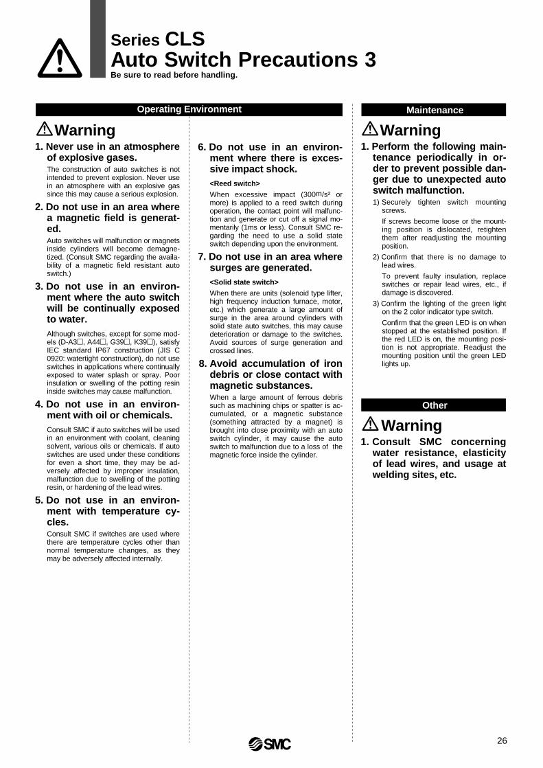
1. Never use in an atmosphere of explosive gases. The construction of auto switches is not intended to prevent explosion. Never use in an atmosphere with an explosive gas since this may cause a serious explosion.
2. Do not use in an area where a magnetic field is generat-ed.Auto switches will malfunction or magnets inside cylinders will become demagne-tized. (Consult SMC regarding the availa-bility of a magnetic field resistant auto switch.)
3. Do not use in an environ-ment where the auto switch will be continually exposed to water.Although switches, except for some mod-els (D-A3, A44, G39, K39), satisfy IEC standard IP67 construction (JIS C 0920: watertight construction), do not use switches in applications where continually exposed to water splash or spray. Poor insulation or swelling of the potting resin inside switches may cause malfunction.
4. Do not use in an environ-ment with oil or chemicals.Consult SMC if auto switches will be used in an environment with coolant, cleaning solvent, various oils or chemicals. If auto switches are used under these conditions for even a short time, they may be ad-versely affected by improper insulation, malfunction due to swelling of the potting resin, or hardening of the lead wires.
5. Do not use in an environ-ment with temperature cy-cles.Consult SMC if switches are used where there are temperature cycles other than normal temperature changes, as they may be adversely affected internally.
6. Do not use in an environ-ment where there is exces-sive impact shock.<Reed switch>
When excessive impact (300m/s² or more) is applied to a reed switch during operation, the contact point will malfunc-tion and generate or cut off a signal mo-mentarily (1ms or less). Consult SMC re-garding the need to use a solid state switch depending upon the environment.
7. Do not use in an area where surges are generated.<Solid state switch>
When there are units (solenoid type lifter, high frequency induction furnace, motor, etc.) which generate a large amount of surge in the area around cylinders with solid state auto switches, this may cause deterioration or damage to the switches. Avoid sources of surge generation and crossed lines.
8. Avoid accumulation of iron debris or close contact with magnetic substances.When a large amount of ferrous debris such as machining chips or spatter is ac-cumulated, or a magnetic substance (something attracted by a magnet) is brought into close proximity with an auto switch cylinder, it may cause the auto switch to malfunction due to a loss of the magnetic force inside the cylinder.
Operating Environment
1. Perform the following main-tenance periodically in or-der to prevent possible dan-ger due to unexpected auto switch malfunction.1) Securely tighten switch mounting
screws.
If screws become loose or the mount-ing position is dislocated, retighten them after readjusting the mounting position.
2) Confirm that there is no damage to lead wires.
To prevent faulty insulation, replace switches or repair lead wires, etc., if damage is discovered.
3) Confirm the lighting of the green light on the 2 color indicator type switch.
Confirm that the green LED is on when stopped at the established position. If the red LED is on, the mounting posi-tion is not appropriate. Readjust the mounting position until the green LED lights up.
Maintenance
1. Consult SMC concerning water resistance, elasticity of lead wires, and usage at welding sites, etc.
Other
Warning Warning
Warning
Series CLSAuto Switch Precautions 3Be sure to read before handling.
26

27
Part Descriptions
3. In order to further improve stopping accuracy, the time from the stop signal to the operation of the lock should be shortened as much as possible.To accomplish this, use a device such as a highly responsive elec-tric control circuit or solenoid valve driven by direct current, and place the solenoid valve as close as possible to the cylinder.
4. Note that stopping accuracy will be influenced by changes in piston speed.When piston speed changes during the course of the cylinder stroke due to variations in the load or disturbances, etc., the dispersion of stopping positions will increase. Therefore, consideration should be given to establishing a standard speed for the piston just before it reaches the stopping position.
Moreover, the dispersion of stopping positions will increase during the cushioned portion of the stroke and during the accelerating por-tion of the stroke after the start of operation, due to the large changes in piston speed.
1. When in a locked condition, do not apply a load ac-companied by an impact shock, strong vibration or turning force, etc.Use caution, because an external action such as an impacting load, strong vibration or turning force, may damage the locking mecha-nism or reduce its life.
2. Consider stopping accuracy and the amount of over-run when an intermediate stop is performed.Due to the nature of a mechanical lock, there is a momentary lag with respect to the stop signal, and a time delay occurs before stop-ping. The cylinder stroke resulting from this delay is the overrun amount. The difference between the maximum and minimum over-run amounts is the stopping accuracy.
• Place a limit switch before the desired stopping position, at a dis-tance equal to the overrun amount.
• The limit switch must have a detection length (dog length) of the overrun amount + α.
• SMC's auto switches have operating ranges from 8 to 14mm (de-pending on the switch model).When the overrun amount exceeds this range, self-holding of the contact should be performed at the switch load side.
∗ Refer to page 2 regarding stopping accuracy.
Selection
1. Construct so that the human body will not come into direct contact with driven objects or the moving parts of the cylinder with brake.Devise a safe structure by attaching protective covers that prevent direct contact with the human body, or in cases where there is a danger of contact, provide sensors or other devices to perform an emergency stop, etc., before contact occurs.
2. Use a balance circuit, taking cylinder lurching into consideration.In cases such as an intermediate stop, where a lock is operated at a desired position within the stroke and air pressure is applied from only one side of the cylinder, the piston will lurch at high speed when the lock is released. In such situations, there is a danger of causing human injury by having hands or feet, etc., caught, and al-so a danger of causing damage to the equipment. In order to pre-vent this lurching, a balance circuit such as the recommended air pressure circuits (page 29) should be used.
3. When designing equipment and machinery, give consideration to clearance and mounting orientation so that manual release of the lock (using the manual release bolt) will be possible.
Design of Equipment and Machinery
Warning
Brake cylinder
Tie-rod nut
Piston rod
Adjustment unit cover
Plug
Manual releasebolt (P. 27 & 28)
Switch for lockunit (P. 29)
Lock monitor (P.28)
Plug with breathing holeLock release port
Cylinder actuation ports@SMC
MODEL CLS125
@SMC
MODELCLS125
Clearance
Lock unit
Base cylinder
Warning
Stop signal
Amount of overrun
140160180200250
125 50
60
708090
Bore size (mm) Clearance (mm)∗ Minimum clearance for manual release
Manualrelease bolt
Series CLSSpecific Product Precautions 1Be sure to read before handling.Refer to pages 21 through 26 for safety instructions, actuator precautions and auto switch precautions.

2. Cautions when using the base unit and when changing bracket positions, etc.The lock unit and cylinder rod cover are assembled as shown in the drawing below. For this reason, it cannot be installed as in the case of common air cylinders, by using the basic type and screwing the cylinder tie-rods directly to machinery.Furthermore, when brackets are replaced, the unit holding tie-rods may become loose and they should be retightened.
1. Adjust the cylinder's air balance.Balance the load by adjusting the air pressure in the front and rear sides of the cylinder with the load connected to the cylinder and the lock in a released condition. Lurching of the cylinder when unlocked can be prevented by carefully adjusting this air balance.
2. Adjust the mounting positions of the detec-tors on auto switches, etc.When intermediate stops are to be performed, adjust the mounting positions of detectors on auto switches, etc., taking in-to consideration the overrun amount with respect to the desired stopping positions.
Caution
JIS B1181 Class 2M14 x 1.5
Mounting Mounting
Warning
Mounting
Caution1. Do not apply an offset load to the piston rod.
Particular care should be taken to match the load's center of gravity with the center of the cylinder shaft. When there is a large discrep-ancy, the piston rod may be subjected to uneven wear or damage due to the inertial moment during locking stops.
3. The adjustment screw inside the adjustment unit cover is set before shipment. Since any discrepancy in this adjustment can cause cyl-inder or lock malfunction, etc., never touch the screw.
4. When raising the unit, do not insert your hands or fingers.As this is a heavyweight product, be sure to use caution.Screw holes for installing eyebolts are provided for ø180, ø200 and ø250. (Eyebolts are not included in the unit.)
Bore size (mm)
125140
160180200
Hexagon socket head taper plug
Rc 1/4
Rc 3/8
250 Rc 3/4
Hexagon socket head taper plug sizes
Adjustment
Bore size (mm)125140160
Tie-rod nut
JIS B1181 Class 2M16 x 1.5
JIS B1181 Class 2M18 x 1.5180
JIS B1181 Class 2M20 x 1.5
Bore size (mm)
200
250
Tie-rod nut
JIS B1181 Class 2M24 x 1.5
Lock unit
Wing nutConical spring washerRod cover
Cylinder tie-rod
Wing nutUnit holding tie-rod
Tie-rod nut,spring washer
3. When installing the cylinder to machinery, etc., secure enough clearance and consider the mounting direction for manual lock release (releasing with the manual release bolt).
Bore size (mm)
140160
125Clearance (mm)
50
60
180 70200 80250 90
∗ Minimum clearance for manual releasem
Manualrelease bolt
1. Be certain to connect the rod end to the load with the lock released.
• If connected when in the locked condition, turning force or a load greater than the holding force may operate on the piston rod and cause damage to the lock mechanism. The CLS series is equip-ped with an emergency unlocking mechanism, however, the load should be connected to the rod end with the lock in the re-leased condition. This can be accomplished manually or by sim-ply connecting an air line to the unlocking port and supplying air pressure of 0.25MPa or more.
2. The unit is shipped from the factory with the lock in the released condition. Since the lock will not operate in this condition, be sure to put it in the locked condition before operation, following the procedure given below.(1) Remove the manual release bolt using a hexagon wrench.(2) Next confirm that the white mark on the brake cylinder's lock
monitor is in the LOCK position.(3) Block the bolt insertion hole with the hexagon socket head
taper plug which is included.
∗ An offset load can be operated if there is an effective guide to absorb all of the generated moment.
X Load center of gravity and cylinder shaft center are not matched.
• Load center of gravity and cylinder shaft center are matched.
Series CLSSpecific Product Precautions 2Be sure to read before handling.Refer to pages 21 through 26 for safety instructions, actuator precautions and auto switch precautions.
28

29
Lock Monitor
Unlocked Locked by operation of brake
1. Be certain to use a pneumatic circuit which will apply balancing pressure to both sides of the pis-ton when in a locked stop.In order to prevent cylinder lurching when restarting or manually un-locking after a locked stop, a circuit should be used to apply balanc-ing pressure to both sides of the piston, thereby canceling the force generated by the load in the direction of piston movement.
2. Use a solenoid valve for unlocking with an effec-tive area that is 25% or more of the effective area of the cylinder drive solenoid valve. The larger the effective sectional area is, the shorter the locking time will be (the overrun amount will be shorter), and stopping accu-racy will be improved.
3. Place the solenoid valve for unlocking close to the cylinder, and no farther than the cylinder drive sol-enoid valve.The shorter the distance from the cylinder (the shorter the piping), the shorter the overrun amount will be, and stopping accuracy will be improved.
4. Allow at least 0.5 seconds from a locked stop (in-termediate stop of the cylinder) until release of the lock.When the locked stop time is too short, the piston rod (and load) may lurch at a speed greater than the control speed of the speed controller.
5. When restarting, control the switching signal for the unlocking solenoid valve so that it acts before or at the same time as the cylinder drive solenoid valve.If the signal is delayed, the piston rod (and load) may lurch at a speed greater than the control speed of the speed controller.
6. Basic circuits
1. [Horizontal]
Pneumatic Circuits
Warning
2. [Vertical]
[Load in direction of rod extension] [Load in direction of rod retraction]
SOL.C SOL.BSOL.A
W
SOL.C SOL.B SOL.A
W
Forward
Backward
3 portnormallyclosed
Brake lever Brake piston
Locking spring
Brake cylinderAuto switch for lock unit
Eccentric cam shaft
Brake shoe holder
Brake shoePiston rod
SOL.A SOL.C SOL.B
Pressurecenter
Regulatorw/checkvalve
WSOL.AONOFFONONONOFFONON
SOL.BONOFFOFFONOFFOFFOFFOFF
SOL.COFFOFFOFFOFFONOFFOFFON
ActionForwardLocked stopUnlockedForwardBackwardLocked stopUnlockedBackward
0.5s ormore0 to0.5s
0.5s ormore0 to0.5s
∗ The condition of the lock monitor and the detection signal from the lock unit switch do not directly confirm the locking condition at the piston rod, but confirm this indirectly from the position of the brake piston.
1. By installing a switch on the brake cylinder of the Series CLS, the operating condition (unlocked side) of the lock unit (brake piston) can be detected as a switch signal.
Lock unit mechanismThe spring force applied to the brake piston is transmitted and magnified through the lever, eccentric cam shaft and brake shoe holder, finally tightening on the piston rod via the brake shoe and locking the piston rod by means of their mutual frictional force.
Auto Switch for Lock Unit
Caution
Caution
FREE LOCK CHECK
FREE LOCK CHECK
FREE LOCK CHECK
Mark (white)
The position of the lock condition mark on the lock monitor gradually moves to the right side with wear of the shoe, etc. When the mark is half way or more into the CHECK zone, this indicates that the brake shoe is near the end of its life. (The brake will not immediately become ineffective in this condition.)
Locked condition(when air is exhausted)
Brake shoe life
Series CLS is equipped with a lock monitor on the lock unit. Use the lock monitor as a criterion to confirm the operating condition of the lock unit (brake piston) and the state of wear (life) of the brake shoe.
∗ Please note that the position of the mark when locked varies somewhat from unit to unit.
Series CLSSpecific Product Precautions 3Be sure to read before handling.Refer to pages 21 through 26 for safety instructions, actuator precautions and auto switch precautions.

1. In locations where the cylinder body will be direct-ly exposed to cutting oil or coolant, etc., a cover or other protection should be provided for the cylin-der body and rod.
Operating Environment
Caution
1. The operating condition of the lock unit (brake pis-ton) can be confirmed externally by means of the lock monitor.1) When the lock monitor mark has moved half way or more into
the CHECK zoneIf used in this condition, the holding force will gradually de-crease. If an operational problem is found in the course of checking the lock's operating condition, early replacement of the cylinder body or lock unit is necessary. Contact SMC re-garding replacement of the lock unit.
2) When the lock monitor mark moves into the CHECK zone prematurelySince there is a possibility of damage to the lock unit, consult SMC after reviewing the method of operation.
2. This cylinder is a non-lube type. Do not lubricate the cylinder or apply grease to the piston rod, as there is a danger of drastically reducing brake per-formance.
3. When replacing seals in the base cylinder, it is recommended that the lock unit be separated from the base cylinder so that replacement work can be done on the cylinder alone. Refer to separate in-structions for seal replacement.
4. Never disassemble the lock unit.
• A heavy duty spring is contained in part of the unit, which pres-ents a serious hazard if disassembly is performed incorrectly.
• In addition, the lock unit is adjusted before shipment. If readjust-ment is not performed correctly after reassembly, a serious dan-ger will be created, as performance will not meet specifications.
Maintenance
Caution
1. The Series CLS manual release mechanism is an emergency unlocking mechanism only.During an emergency when the air supply is cut off, it is used to alle-viate a problem by forcibly pulling the brake piston back to release the lock.
2. In the case of large bore cylinders, even when the lock is released, operational resistance as shown in the table below is generated in a non-load state.
3. Care must be taken, because if the manual release bolt is screwed in only part way and air is supplied to the unlocking port, or it is changed from a sup-ply to an exhaust state, the head of the manual re-lease bolt may be ejected from the end of the brake cylinder or be pulled in creating a serious hazard.
Unlocking procedure using the manual release bolt1. Remove the hexagon socket head taper plug
which is on the same side as the brake cylinder adjustment unit cover.
2. Insert the manual release bolt (see table below) in-to the threads and screw it in clock-wise.
3. The lock is released by screwing in the manual re-lease bolt until the white mark of the lock monitor on the top of the brake cylinder moves to the FREE position.
Manual Unlocking Manual Unlocking
Caution
1. Never perform the manual unlocking opera-tion (with the manual release bolt, etc.) until safety has been confirmed.1) If air pressure is applied to only one side of the cylinder when un-
locking is performed, the moving parts of the cylinder may lurch at high speed causing a serious hazard.
2) When unlocking is performed, be sure to confirm that personnel are not within the movement range of the load, and also that no problems will be caused if the load is actuated.
2. When unlocking in the case of loads which move up and down, take measures to assure that the load will not drop.1) Perform work with the load at its lowest position.2) Prevent dropping of the load by using a support or brace, etc. 3) Verify that balanced pressure is applied to both sides of the pis-
ton.
Warning
Locked(with air evacuated)
[Principle]When the manual release bolt is screwed in clock-wise, the brake pis-ton is pulled back and the spring is compressed. This causes the lever to be returned, releasing the lock.
Manually unlocked(with manual release bolt screwed in)
Manualrelease bolt
Lock springBrake piston
Brake lever
Eccentriccam shaft
Brake shoeholder
∗ In case the manual release bolt is not available, use an appropriate hexagon socket head bolt (full thread) as shown above.
125
M6 x 1.0 x 35l
30
140
M6 x 1.0 x 40l
32
160
M8 x 1.25 x 40l
35
180
M10 x 1.5 x 50l
40.5
200
M10 x 1.5 x 55l
45
250
M12 x 1.75 x 70l
55
Unit: mm
Bore size (mm)
Manualrelease boltScrew depth
125
962
180
1995
140
1206
200
2463
250
3848
160
1576
Bore size (mm)
Operationalresistance (N)
Series CLSSpecific Product Precautions 4Be sure to read before handling.Refer to pages 21 through 26 for safety instructions, actuator precautions and auto switch precautions.
30

31
1. In order that the originally selected maximum speed is not exceeded, be certain to use a speed controller and adjust if so that movement through the total movement distance of the load takes place in no less than the applicable movement time.The movement time is the time that is necessary for the load to travel the total movement distance from the start without any intermediate stops.
2. In cases where the cylinder stroke and the movement distance of the load are different (double speed mechanism, etc.), use the movement distance of the load for selection purposes.
Find the maximum load speed: V
Selection Example
Caution
Example)
• Load weight: m = 320kg• Movement distance: st = 400mm• Movement time: t = 2s• Load condition: Vertical downward = Load in direction of rod extension • Operating pressure: P = 0.4MPa
Step 1: From graph 1 find the maximum movement speed of the load
∴ Maximum speed V: approx. 280mm/s
Step 2: Select Graph 6 based upon the load condition and operating pressure, and then from the intersection of the maximum speed V = 280mm/s found in Step 1, and the load weight m = 320kg
∴ ø140→ select a CLS140 or larger bore size.
Find the maximum load speed: V(mm/s) from the load movement time: t(s) and the movement distance: st(mm).
Find the cylinder bore size.
Select a graph based upon the load condition and operating pressure, and then find the point of intersection for the maximum speed found in Step 1 and the load weight. Select the bore size on the line above the point of intersection.
Load condition Operating pressure
from 0.4MPa Graph 3
from 0.3MPa Graph 2
from 0.5MPa Graph 4
from 0.4MPa Graph 6
from 0.3MPa Graph 5
from 0.5MPa Graph 7
Step 2
Step 1
V'
V
Cylinder stroke
W
Movementdistance of load
F
m
F
m
F
Precautions on Model Selection
Direction of load at right angle to rod(∗ Being held by a guide)
Load in direction of rod extensionLoad in direction of rod retraction
Graph 15040
1600st2000st2400st
1400st1200st1000st800st600st500st400st
300st
200st
100st
30
20
10
543
2
1
0.50.40.3
0.2
0.1100 200 300 400 500
[Example]
Load
mov
emen
t tim
e: t(
S)
Maximum speed: V(mm/s)
m
Series CLSModel Selection
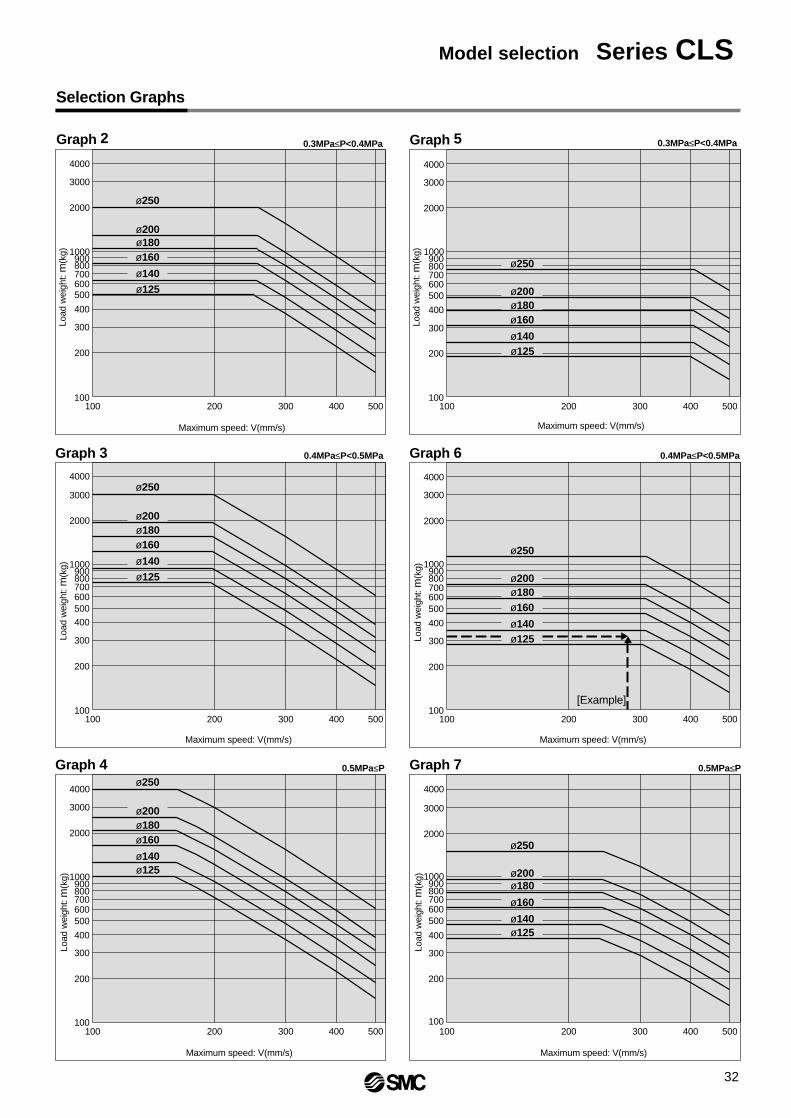
Graph 6Graph 3
Graph 7Graph 4
100 500400300200
100 500400300200
100
1000
200
300
400
500
2000
4000
3000
700800900
600
100 500400300200100
1000
200
300
400
500
2000
4000
3000
ø125700800900
600
100 500400300200
100 500400300200
100
100
1000
200
300
400
500
2000
4000
3000
700800900
600
100 500400300200100
1000
200
300
400
500
2000
4000
3000
700800900
600
1000
2000
3000
4000
400
200
100
300
500
700800900
600
1000
2000
4000
3000
400
200
300
500
700800900
600
ø160
ø140
ø180
ø250
ø200
ø125
ø160
ø140
ø180
ø250
ø200
ø125
ø160
ø140
ø180
ø250
ø200
ø125
ø160
ø140
ø180
ø250
ø200
ø125
ø160
ø140
ø180
ø250
ø200
ø125
ø160
ø140
ø180
ø250
ø200
[Example]
Maximum speed: V(mm/s)
Load
wei
ght:
m(k
g)
Maximum speed: V(mm/s)Lo
ad w
eigh
t: m
(kg)
Maximum speed: V(mm/s)
Load
wei
ght:
m(k
g)
Maximum speed: V(mm/s)
Load
wei
ght:
m(k
g)
Maximum speed: V(mm/s)
Load
wei
ght:
m(k
g)
Maximum speed: V(mm/s)
Load
wei
ght:
m(k
g)
Selection Graphs
Graph 5Graph 2 0.3MPa≤P<0.4MPa 0.3MPa≤P<0.4MPa
0.4MPa≤P<0.5MPa 0.4MPa≤P<0.5MPa
0.5MPa≤P 0.5MPa≤P
Model selection Series CLS
32

EUROPESPAIN/PORTUGALSMC España, S.A.
SWEDENSMC Pneumatics Sweden AB
SWITZERLANDSMC Pneumatik AG.
UKSMC Pneumatics (U.K.) Ltd.
ASIACHINASMC (China) Co., Ltd.
HONG KONGSMC Pneumatics (Hong Kong) Ltd.
INDIASMC Pneumatics (India) Pvt. Ltd.
MALAYSIASMC Pneumatics (S.E.A.) Sdn. Bhd.
PHILIPPINESSMC Pneumatics (Philippines), Inc.
SINGAPORESMC Pneumatics (S.E.A.) Pte. Ltd.SOUTH KOREASMC Pneumatics Korea Co., Ltd.
TAIWANSMC Pneumatics (Taiwan) Co., Ltd.
THAILANDSMC Thailand Ltd.
NORTH AMERICACANADASMC Pneumatics (Canada) Ltd.
MEXICOSMC Corporation (Mexico) S.A. de C.V.USASMC Pneumatics, Inc.
SOUTH AMERICAARGENTINASMC Argentina S.A.
BOLIVIASMC Pneumatics Bolivia S.R.L.
BRAZILSMC Pneumaticos Do Brazil Ltda.
CHILESMC Pneumatics (Chile) S.A.
VENEZUELASMC Neumatica Venezuela S.A.
OCEANIAAUSTRALIASMC Pneumatics (Australia) Pty. Ltd.
NEW ZEALANDSMC Pneumatics (N.Z.) Ltd.
EUROPEAUSTRIASMC Pneumatik GmbH
CZECHSMC Czech s.r.o.
DENMARKSMC Pneumatik A/S
FINLANDSMC Pneumatiikka OY
FRANCESMC Pneumatique SA
GERMANYSMC Pneumatik GmbH
HUNGARYSMC Hungary Kft.
IRELANDSMC Pneumatics (Ireland) Ltd.
ITALYSMC Italia S.p.A.
NETHERLANDSSMC Pnuematics BV.
NORWAYSMC Pneumatics Norway A/S
ROMANIASMC Romania s.r.l.
RUSSIA SMC Pneumatik LLC.
SLOVAKIASMC Slovakia s.r.o.
SLOVENIASMC Slovenia d.o.o.
SMC'S GLOBAL MANUFACTURING, DISTRIBUTION AND SERVICE NETWORK
1-16-4 Shimbashi, Minato-ku, Tokyo 105-0004, JAPANTel: 03-3502-2740 Fax: 03-3508-2480URL http://www.smcworld.com© 2000 SMC CORPORATION All Rights Reserved
Specifications are subject to change without prior notice and any obligation on the part of the manufacturer.
Printed in Japan.1st printing March, 2000 D-SMC.L.A. P-80 (JT)