cylinder liners lesson four. 1.liner definition a removable component, cylindrical in shape,...
TRANSCRIPT

CYLINDER LINERS
LESSON FOUR

1. LINER DEFINITION
A removable component, cylindrical in shape, inserted into the engine block. It can be replaced when worn out.


1. LINER DEFINITION
A removable component, cylindrical in shape, inserted into the engine block. It can be replaced when worn out.
1.1 FUNCTION
It provides the surface for the piston to slide and carry out its compression task.


1. LINER DEFINITION
A removable component, cylindrical in shape, inserted into the engine block. It can be replaced when worn out.
1.1 FUNCTION
It provides the surface for the piston to slide and carry out its compression task.
1.2 TYPES
Wet liners ( the water is in direct contact with outer surface of the liner );
Dry liners ( the water is in indirect contact with outer surface of the liner, i.e. cylinder casting contains wet jackets ).
1.3 MANUFACTIRING
Grey cast steel + vanadium & titanium
Chromium plate liners ( to reduce wear rate ),
Close grained cast iron or
Fine lamellar cast iron ( in recent designs ).
It can be made in one ( single ) piece or in two ( double ) piece element

1.4 CONDITIONS TO MEET
Strenght, wear resistance & corrosion ressistance ( sulphur in fuel ).

1.4 CONDITIONS TO MEET
Strenght, wear resistance & corrosion ressistance ( sulphur in fuel ).
1.5 LIMITATIONS
Thickness ( 0,085D – 0,1D ) because of:
cooling and thermal stresses.


1.4 CONDITIONS TO MEET
Strenght, wear resistance & corrosion ressistance ( sulphur in fuel ).
1.5 LIMITATIONS
Thickness ( 0,085D – 0,1D ) because of:
cooling and thermal stresses.
1.6 CONNECTIONS AND ARRANGEMENTS*
1.6.1 Connections
At the top – flange ( for securing in the cylinder block or to the water jacket ).
1.6.2 Arrangements
Below the top flange – joint ring ( copper or heat ressistant rubber );
Lower end of the liner – rubber ring seal for the bottom of water space.
Between the upper & lower rings – leek-off hole ( a drain for oil & water out of the engine ).

1.7 DESIGN
Uninterrupted or continuous liner ( in 4-stroke enginers );


1.7 DESIGN
Uninterrupted or continuous liner ( in 4-stroke enginers );
Ported liner ( 2-stroke engines )

1.7 DESIGN
Uninterrupted or continuous liner ( in 4-stroke enginers );
Ported liner ( 2-stroke engines )
1.8 SCAVENGING
Traditional two stroke loop scavange engines have ports midway along their lenght;


1.7 DESIGN
Uninterrupted or continuous liner ( in 4-stroke enginers );
Ported liner ( 2-stroke engines )
1.8 SCAVENGING
Traditional two stroke loop scavange engines have ports midway along their lenght;
Modern two stroke engines are provided with uniflow scavenging system.

2. COOLING*
2.1 PURPOSE
Reduction of the surface temperature allows for adequate lubrication, ensures gas seal & diminish liner & piston ring wear.
Limit thermal expansion thereby maintaining the piston clearance.

2. COOLING*
2.1 PURPOSE
Reduction of the surface temperature allows for adequate lubrication, ensures gas seal & diminish liner & piston ring wear.
Limit thermal expansion thereby maintaining the piston clearance.
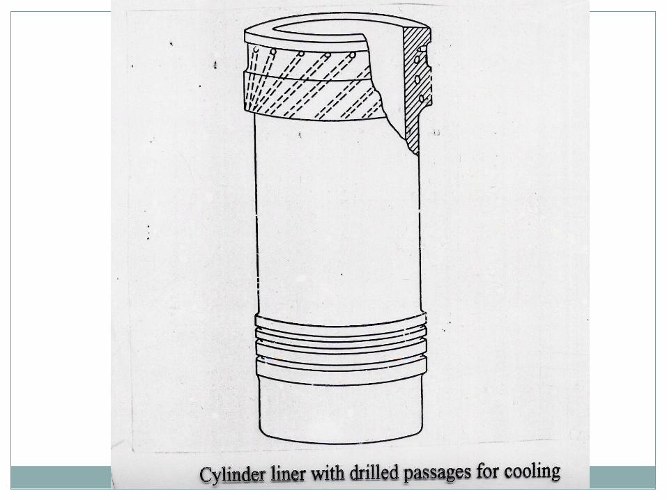
2.2 IN WET LINERS
By circulation of chemically treated fresh water ( to reduce corrosion and prevent scale formation ) in the upper ends of liners.


2. COOLING*
2.1 PURPOSE
Reduction of the surface temperature allows for adequate lubrication, ensures gas seal & diminish liner & piston ring wear.
Limit thermal expansion thereby maintaining the piston clearance.
2.2 IN WET LINERS
By circulation of chemically treated fresh water ( to reduce corrosion and prevent scale formation ) in the upper ends of liners.
More effective cooling may be obtained by bore-cooled liners, i.e. through additional drillings for cooling water made


3. LUBRICATION*
3.1 PURPOSE
To reduce piston ring friction & wear;
Oil film acts as gas seal to ( prevent blow by ) & corrosion inibitor;

3. LUBRICATION*
3.1 PURPOSE
To reduce piston ring friction & wear;
Oil film acts as gas seal to ( prevent blow by ) & corrosion inibitor;
3.2 TYPE
In large crosshead-type engines – sepatate cylinder lubrication systemfitted

3. LUBRICATION*
3.1 PURPOSE
To reduce piston ring friction & wear;
Oil film acts as gas seal to ( prevent blow by ) & corrosion inibitor;
3.2 TYPE
In large crosshead-type engines – sepatate cylinder lubrication systemfitted
In trunk piston engines – by oil splashing from the crankcase.
3.3 OIL INJECTION
Through lubricator quills – timed to inject oil between the piston rings as they pass.


4. GAUGING*
It is made internally during cylinder overhaul after 6000 – 8000 hours.
4.1 GAUGE ( micrometer & extension bar / template bar / gaugin strip).


4. GAUGING*
It is made internally during cylinder overhaul after 6000 – 8000 hours.
4.1 GAUGE ( micrometer & extension bar / template bar / gaugin strip).
4.2 READINGS ( at 6 – 8 vertical positions – total wear from original & wear since last recording )


4. GAUGING*
It is made internally during cylinder overhaul after 6000 – 8000 hours.
4.1 GAUGE ( micrometer & extension bar / template bar / gaugin strip).
4.2 READINGS ( at 6 – 8 vertical positions – total wear from original & wear since last recording )
4.3 WEAR RATES*
High at the beginning, later almost constant ;
acceptable wear – 0.1 mm per 1000 hours;
maximum wear before renewal – app. 0.6-0.8 % of the original diametar )


5. WEAR CAUSES & RESULTS / REMEDIES


5. WEAR CAUSES & RESULTS / REMEDIES
5.1 FRICTIONAL WEAR ( between the liner surface & rings )
It depends upon:
material,
surface conditions,
efficiency of lubrication,
piston speed,
engine loading,
maintanance of piston rings,
combustion efficiency &
contanination of air and fuel.

5.2 CORROSION ( lower part of the liner )
engines burning heavy fuel & high sulphur content fuel – to be neutralised by alkaline type cylinder oil;
too low jacket cooling water temperature leads to sulphuric acid corrosion – keep jacket temperatures above dew point
the charge air intercooler is undercooled and condensed water droplets are carried into the cylinder by scavenge air.
5.3 ABRASION ( hard particles )
Products of mechanical wear, corrosion & combustion – cylinders to be regularly cleaned and inspected.

6. RENEWAL & PREPARATION FOR RUNNING-IN
6.1 RENEWAL
At the top of the piston travel & at port bars
ports to be cleaned,
sharp edges to be removed,
lubricators to be tested,
possible craks to be inspected

6. RENEWAL & PREPARATION FOR RUNNING-IN
6.1 RENEWAL
At the top of the piston travel & at port bars
ports to be cleaned,
sharp edges to be removed,
lubricators to be tested,
possible craks to be inspected
6.2 PREPARATION FOR RUNNING-IN*
New liners are produced with slightly rough surface to retain oil & facilitate running in.
New liners require honing ( braking the liner glze ).
Hard wearing surfaces are obtained by liner bore nitrading.

