cyclic loading tests on soft-first-story rc …data.jci-net.or.jp/data_pdf/31/031-01-2068.pdf · of...
TRANSCRIPT

-Technical Paper-
CYCLIC LOADING TESTS ON SOFT-FIRST-STORY RC FRAMESRETROFITTED WITH THICK HYBRID WING-WALL
Pasha JAVADI*1, Tetsuo YAMAKAWA*2, Makoto KOBAYASHI*3, Michiyo GAJA*4
ABSTRACTThree one-bay two-story RC frames which had the characteristics of soft-first-story frames (pilotis frames)were retrofitted with thick hybrid wing-wall method to find out a desired seismic performance and conse-quently propose an appropriate scheme of this retrofit type. In retrofitting procedure, channel-shaped steelplates jacketed the boundary columns of the soft-story and extended to the bay of the frame through theadditional steel plates. In this method, the additional thick hybrid wing-walls not only increase the lateralstrength and stiffness of RC frames, but also considerably improve the ductility of non-ductile RC frames.Keywords: soft-first-story, pilotis frame, seismic retrofitting, seismic strengthening, thick hybrid wall
1. INTRODUCTION
Numerous total and partial collapses of reinforcedconcrete (RC) buildings occurred during the 1995 Kobeearthquake in Japan. Soft-first-story (i.e., pilotis) mecha-nism was the most common type of failures that occurreddue to discontinuity of lateral resisting system in theground floor to provide retail occupancy or parking.Nowadays, a large number of reinforced concrete build-ings in use have similar characteristics to those that col-lapsed during the past earthquakes.
Previous investigations by Rahman et al. [1] on one-bay one-story RC bare frames demonstrated that utiliz-ing thick-hybrid-wall method not only significantly in-creases the lateral strength and stiffness of soft-storyframes, but also considerably improves the ductility ofthe retrofitted frame, and therefore the proposed tech-nique provided an adequate seismic performance.
In this paper, the attention mainly focuses on obtain-ing a desirable retrofit scheme of thick hybrid wing-wallfor soft-first-story RC frames. Three one-bay two-storyspecimens with soft-first-story characteristics were planedto retrofit with different schemes to verify the possiblefailures modes of this retrofit type.
2. TEST PLAN
In this study, experimental investigations wereconducted on three soft-first-story frames retrofitted bythick hybrid wing-wall method. In all of the testspecimens, the geometric dimensions and thereinforcement patterns of the RC frames were identical.Dimensions of sections, reinforcements details and
properties of materials are given in Fig. 1 and Table 1,respectively. All specimens were fabricated in two stages.In the first stage, the RC frames were cast and cured, andin the second stage, after 28 days, the additional concreteof the wing-walls were cast (see Fig. 2). Main objectiveof design of test specimens with different retrofittingdetails is to find out a desired retrofit scheme.
The specimens were subjected to constant axial loads(N=0.2sBbD per column) by force-controlled programand to cyclic horizontal loads by displacement-controlledprogram. In order to provide the lateral distribution ofseismic induced force in the height of building, at eachhorizontal loading stage, 5/11 and 6/11 of the base shearforce were applied on the first and second stories,respectively, according to the factor (Ai) for verticaldistribution of the seismic story shear force used inBuilding Standard Law of Japan. The displacement-controlled program and the schematic view of test setupare illustrated in Fig. 3.
As shown in Fig. 2, specimen R07P-P0 is a soft-first-story benchmark specimen. The shear span-to-depthratio of the columns (considering their clear heights) isM/Vd=2.5, and that of the top beam (considering its clearspan) is M/Vd=2.65. The scale factor of test specimenswas about 1/4~1/3 of a low-rise school building designedto the pre-1971 Building Standard Law of Japan. Theratio of transverse reinforcement of the column was thepoor amount of rw=0.12%, and the ratio of theirlongitudinal reinforcements was rg=1.85%. The lateralstrength and stiffness of the second story which consistedof shear wall was considerably greater than first story toobtain a frame with soft-first-story behavior.
Specimen R06P-WW was retrofitted with thick
*1 Graduate Student, Graduate School of Eng. and Science, University of the Ryukyus, M. Eng., JCI Member*2 Prof., Department of Civil Eng. and Architecture, University of the Ryukyus, Dr. Eng., JCI Member*3 Graduate Student, Graduate School of Eng. and Science, University of the Ryukyus, JCI Member*4 Research Assistant, University of the Ryukyus, JCI Member
コンクリート工学年次論文集,Vol.31,No.2,2009
-403-

101010
10
hybrid wing-wall. In retrofitting procedure, channel-shaped plain steel plates (t=2.3mm) jacketed the boundarycolumns, and extended into the bay of the first storythrough the additional deck steel plates (t=1.2mm). Bolts(M12) were stitched the deck steel plates installed at twosides of the column. In this case-study, the depth of theadditional wing-wall (2D) was two times of the depth ofthe column (D), and its width was equal to that of thecolumn. To prevent crushing of concrete at the exposedface of wing-wall, transverse reinforcements (D6-@100mm) were arranged at the exterior side of the wing-wall. The steel plates were also used as a formwork forcasting the additional concrete of wing-wall. Additionalconcrete of wing-wall was cast vertically up to the bottomface of the top beam. After casting the additional concrete,the existing gap (about 10mm) between the exterior facesof the column and steel plates were filled by mortar-grout.
The retrofitting procedure of specimen R08P-WN wassame as specimen R06-WW, but in this test specimenplain steel plates (t=2.3mm) was used instead of deck
steel plates. Also, PC bars (high-strength steel bars, 13f)were stitched the plain steel plates at two sides of thecolumn instead of bolts (M12). After hardening theadditional concrete and before test, the PC bars crossingthe body of wing-wall were fastened up to a tensile strainof about 2500μ.
In specimen R08P-WA, the retrofitting schemefollowed same procedure with specimen R08P-WN, butin this specimen it was planed to perfectly prevent thepossible shear sliding at the bottom and the top of theadditional wing-walls. For the sake of aforementionedreason, the steel plates in the wing-wall parts wereextended up to about the middle of the top beam, andthey were anchored to the beam by means of PC bars.Moreover, a disk-anchor (see Fig. 4) was installed at thebottom of each wing-wall to suppress the possible shear-sliding at this surface. Disk distributes the shear stress at
Fig. 1 Details of reinforcements (unit: mm)
Cro
ss s
ectio
n of
colu
mn
Spec
imen
sB
Iden
tical
deta
ils
Fig. 2 Details of test specimens
R08P-WN R08P-WAR07P-P0
Axial force ratio, N/(bDsB)=0.2 (per column); sB:add. is add. concrete strength (MPa); Reinf. in column: -main reinf.: 8-D10 (pg=1.85%), hoop:3.7f@105 (pw=0.12%); Reinf. in beam (1st-st.): -main reinf.: 4-D13 (pg=1.63%), stirrup: D6-@120 (pw=0.43%); Reinf. in beam (2nd-st.): -mainreinf.: 6-D19 (pg=2.46%), stirrup: D10-@120 (pw=0.59%); Reinf. in shear wall: -3.7f-@60 single (horizontal & vertical) (pw=0.30%). (unit: mm)
R06P-WW
3.7f@105(pw=0.12%)
Steel plate (t=2.3mm) Bolt (M12)
Add. reinf.(D6-@100)
Steel deck plate(t=1.2mm)
8-D10(pg=1.85%)
b=175mm
D=175mm
sB(frame)=24.1 sB(frame)=34.0 , sB(add.)=30.4 sB(frame)=24.6, sB(add.)=31.1
875
250
875
500
350
1500
3.7f-@60rw=0.30%
All columns
3.7f-@105175
8-D10
175 rg=1.85%
rw=0.12%
Beam(1st-story)125
D6-@120
3.7f-@60
60
4-D13
rw=0.30%
250 rg=1.63%
rw=0.43%
349 1)
355 2), 3)
359 3)
342 1)
725 3)
650 1)
683 2)
617 3)
432 1)
504 2)
449 3)
1220 2), 3)
268 1)
348 1)
335 2)
358 3)
Notes: a=cross sectional area; sy=yield strength of steel; ey=yield strain ofsteel; Es=Young’s modulus of elasticity; 1) for R06P; 2) for R07P; 3) for R08P.
Table 1 Properties of steel materials
202201179201
208202188175194153200203212209218
0.170.180.200.17
0.310.340.330.250.260.290.610.130.160.160.16
PC bar
a(cm2)
sy(MPa)
ey(%)
Es(GPa)
0.71Rebaror
Dowel
Hoopor
Stirrup
Plain plate
D10
D13
M16
3.7f
D6
13ft=1.2mm
t=2.3mm
1.27
0.11
0.32
1.33-
-
1.57 - -
Steel material
Deck plate
D 2D
b
Mortargrout
Add.conc.
sB(frame)=25.1, sB(add.)=32.9Disk-anchor (Fig. 4)
b
D 2D
Mortargrout
Add.conc.
D6-@100
PC bar (13f)Steel plate (t=2.3mm)
b
D 2DSteel plate (t=2.3mm) PC bar (13f)
Mortargrout Add. reinf.(D6-@100)
Add.conc.
16753D+12.3
D=175
1010
3D+12.3
3D+12.3 3D+12.3
3D+12.3 3D+12.3
-404-

R08P-WN
Fig. 3 Test setup and loading program
1. Servohydraulic actuator2. Horizontal loading reaction wall3. Hydraulic oil jack4. Load cell5. Counter balance6. Specimen7. Long PC bars8. Strong floor
-4-2024
0 5 10 15 20No. of cycle
d (cm) Loading program
1
2
3
4
5
5
6
7
8 Å•F.L
the shear sliding plane along its width to suppress theconcentration of shear-sliding force induced at potentialsliding surface. Anchors were embedded to panel-wall witha length of l=130mm, and to the stub with a length ofl=130mm according to manufacturer’s instructions. In thisspecimen, PC bars crossing the body of wing-wall werefastened up to a tensile strain of about 2500μ.
3. EXPERIMENTAL RESULTS AND DISCUSSIONS
In specimen R07P-P0, flexural cracks formed at theends of the columns at drift angle of R=0.5% (R=d/h,where d= horizontal displacement of first story and h=theheight of first story) as well as shear cracks appeared atthe same zones at drift angle of R=0.75%. The lateralstrength of the specimen was governed by formation offlexural plastic hinges at both ends of the first storycolumns, but the specimen finally collapsed due to shearfailure at flexural plastic hinge zone in right-side columnat drift angle of R=1.64%.
The specimen R06P-WW is retrofitted by additionalwing-wall. The wing-wall resisted against the lateral loadby action of compression strut. Because of long-lengtharm between tension and compression zones at both endsof wing-wall-column, the longitudinal reinforcementsprematurely yielded at drift angle of R=0.3%. Afterloading test, the jacketing deck steel plates were detached,and it was observed that a diagonal shear crack had formedin each wing-wall. The lateral displacement of thespecimen was governed by flexural deformation of wing-wall-column and overall flexural behavior of the specimen(overturning resistance). Considering this combinedmechanism, when the specimen was pushed from left toright, it is expected the compression force in the wing-wall at right-side column would be significantly greaterthan that at left-side column due to overturning resistance.This mechanism was confirmed through the direction ofdiagonal shear cracks in the wing-walls. In each direction,the wing-wall with higher compression force in its strutdiagonally cracked. Calculation of shear strength of wing-
R08P-WA
-300-200-100
0100200300
-4 -2 0 2 4R(%)
V(kN)
0.8Vmax
0.8Vmax
Vmax=92.1kN
Vmax=-101.84kN
-4 -2 0 2 4R(%)0.8Vmax
0.8VmaxVmax=308.6kN
Vmax=-294.7kN
-4 -2 0 2 4R(%)0.8Vmax
0.8VmaxVmax=271.0kN
Vmax=-272.8kN
R07P-P0
Fig. 5 Experimental V-R relationships, crack patterns and experimentally observed mechanisms
R06P-WWN=0.2sBbd N N=0.2sBbd N N=0.2sBbd N N=0.2sBbd N
6/11V
5/11V
Shearcrack
(Push)
(Push)
Note: Major mechanisms of the specimens are as follows (due to push loading):R07P-P0: At first, flexural plastic hinges formed at both ends of the columns, and finally shear failure occurred at the plastic hinge zone of right-side column.R06P-WW: At left-side column, plastic hinges formed, but at right-side column before perfect formation of plastic hinge, strut of wing-wall cracked.R08P-WN: Initially the plastic hinge formed at both ends of columns, but as the longitudinal reinforcements at top yielded the punching failure happened.R08P-WA: Plastic hinges formed at both ends of columns. This mechanism represents the desired performance of this type retrofit.
Plastic hinge
Shear failure
Shear wallwithout damage Plastic hinge
Shear-punching
Plastichinge
Plastichinge
-4 -2 0 2 4R(%)0.8Vmax
0.8Vmax
Vmax=343.7kN
Vmax=-327.12kN
Fig. 4 Details of disk-anchor
105mm
25mm25mm105mm
f=90mm
21mm
90mm Disk
Anchor(M16)
Wall
Stub
l
l
h
-405-

(2)
wall is deferred to Section 4. The governing mechanismsof the specimens are shown in Fig. 5.
In specimen R08P-WN, due to long-length armbetween tension and compression zones at wing-wall-columns, the longitudinal reinforcements of the boundarycolumns at bottoms yielded at drift angle of R=0.3%.The flexural cracks appeared at the bottom of the columnsat drift angle of R=0.5%. At the top sections of thecolumns, the flexural tension and compression stresses,and shear-friction stress mainly acted. Since the tensionactions of longitudinal reinforcements contribute in bothflexural and shear-friction resistances, the exactevaluation of shear-punching at the top of columnsbecomes complex. In this specimen the sections ofcolumns initially withstood against shear-punchingthrough the shear-friction resistance, but by precedingthe loading test, the longitudinal reinforcements graduallyentered to the inelastic state due to flexural behavior, andconsequently the shear-punching resistance considerablydecreased. As the longitudinal reinforcements at the topof column yielded, the lateral resistance of the specimensuddenly dropped due to shear-punching failure (see V-Rrelationship of specimen R08P-WN in Fig. 5). After that,the shear-sliding resistance at the compression zonemaintained the lateral strength, and the V-R responseexhibit a ductile response up to drift angle of R=5.0%.
In specimen R08P-WA, the longitudinalreinforcements of boundary columns at bottom yieldedat drift angle of R=0.3%. The flexural cracks at the bottomof wing-wall-columns appeared at drift angle of R=0.5%.Moderate strength degradation was obvious in the V-Rrelationship of specimen R08P-WA that results fromcrushing of concrete at compression zone and bucklingof longitudinal reinforcements. The resisting forcemaintained greater than 0.8 Vmax up to drift angle ofR=5.0%, and the overall response of the specimen showsa ductile behavior. To verify the shear sliding resistancecarried by steel plates at top of wing-wall, shear strain-gauges were attached at that level. The produced shearforce in the steel plates that resisted against shear-sliding
was about 27% of overall lateral strength of the specimen.It should be emphasized the reduction of lateral strengthin specimen R08P-WN due to shear-punching failure wasabout 18% of its overall lateral strength. Comparisonbetween the behavior of specimens R08P-WN and R08P-WA exhibits the efficiency of steel plates in shear-slidingresistance at the top of wing-wall-column. Thecomparisons of experimental skeleton curves andaccumulative absorbed energy are shown in Fig. 6. Itshould be noted the lateral resisting force of specimenR08P-WA is larger than R06P-WW, but the accumulativeabsorbed energy is almost same due to different shape ofhysteretic response resulting from different mechanisms.
4. CALCULATION OF LATERAL STRENGTHS
The lateral strengths of the specimens were governedby ultimate flexural strength of wing-wall-column, shearsliding at top and bottom of wing-wall-column or theshear resistance of wing-wall-column. The flexuralstrength of the wing-wall-column can be calculated bysection analysis considering two conditions, when thecolumn is in compression or when the wing-wall is incompression. Simplified equations in calculating theflexural strength of wing-wall-column were proposed byRahman et al. [1]. In this paper, the attention mainlyfocuses on calculating the shear strength and shear slidingresistance of column retrofitted by thick hybrid wing-wall.
4.1 Shear StrengthIn calculating the shear strength of wing-wall-column,
both the arch action of wing-wall-column and the shearresistance of jacketing steel plates should besuperimposed. The resultant shear strength can becalculated as follows;
V=Va(arch action) + Vs (steel plate) (1)
(a) Arch Action of Wing-wall-column (Va)As shown in Fig. 7, arch action of wing-wall column
is calculated based on the proposed approach by Nielsen[2] for a beam without transverse reinforcements.Considering the lower bound solution, the arch can obtainthe maximum possible load when the depth of the arch ishalf of depth of the section. In the proposed mechanismfor wing-wall-column, it is considered the depth of thearch is half of depth of the wing-wall-column. Theapproach to calculate the shear strength is as follows;
Va=0.5(1+b)bDnsBtanq
(3)
2007.0 Bsn -=
0.1=n
DH
DH
)1()
)1((1tan 2
bbq
+-
++=
(for steel deck plate) (4)
(for steel plain plate) (5)0
20
40
60
80
100
0 1 2 3 4 5
R(%)
R08P-WA
R05P-P0
W(kNm)
R08P-WNR06P-WW
0
100
200
300V(kN)
R(%)
R08P-WA R08P-WN
R07P-P0
R06P-WW
Fig. 6 Comparison of (a) skeleton curve and (b) accumulative absorbed energy
(a)
(b)
where n is confinement effectiveness factor, sB is thecylinder strength of concrete and b is the minimum width
-406-

where E and Fys are elasticity modulus and yield stress ofsteel plate. Other parameters are depicted in Fig. 7. Incalculating the shear resistance of jacketing steel plate,it was supposed that the shear force perfectly transferfrom PC bars to the jacketing steel plate. The shearresistance of PC bars and bearing capacity of the providedholes at steel plates were suggested by Yamakawa et al.[4]. In the most cases, the shear strength of steel plate isthe lowest value compared to shear strength of PC barsand bearing capacity of the provided holes.
4.2 Shear SlidingIn column retrofitted by thick hybrid wing-wall, shear
sliding is likely to happen at top and bottom of wing-wall-column. The concrete at compression zone and thelongitudinal reinforcements withstand against shearsliding by shear friction resistance and dowel action,respectively. If the steel plate at wing-wall part anchoredto the beam (such as specimen R08P-WA), the shearsliding resistance at potential sliding plane, at top of wing-wall-column, will considerably increase. Moreover, at thebottom of wing-wall, additional stud dowels or disk-anchors can be installed to ensure the shear slidingresistance. Shear sliding can be calculated bysuperposition of different components as follows;
1) Total shear sliding resistance:
Vn= Vns+Vnc + (Vs or Vda ) (9)
2) Dowel action resistance by kinking (Vns; forlongitudinal reinforcement) [1]:
Vns=0.25fy As (10)
3) Concrete in net compression zone (Vnc ):A. For concrete placed against hardened concrete notintentionally roughened [5], when the compressionzone is in wing-wall (m=0.6), see Fig. 7:
Vnc= m Nc < {0.2sB Ac & 5.5Ac}; (N, mm) (11)
B. For concrete monolithically cast [6], whencompression zone is in column (m=1.4), see Fig. 7:
Vnc= m (rs fy+Nc ) < {0.2sB Ac & 5.5Ac}; (12)
Vnc= m Nc < {0.6sB Ac & 14.5Ac}; if Nc> 5.5Ac (13)
where sB = cylinder strength of concrete, Ac = the netcompression zone area, fy = yield strength ofreinforcement, As = the cross-section area ofreinforcements, rs = ratio of longitudinal reinforcement,m = coefficient of friction and Nc = compression force onconcrete. Evaluation of shear-friction by Valluvan et al.[6] revealed that if the compression force is greater than5.5Ac (N, mm), the resistance by dowel action ofreinforcements will not be effective.
Calculation of shear sliding resistance of steel platesanchored to beam Vs is same as that calculated for shear
of wing-wall or top beam and other parameters are givenin Fig. 7. In case of using steel deck plate, the confinementeffect of steel deck plate is neglected due to its low out-of-plane resistance (see Eq. 4). But, in case of steel plainplate, since it has considerable resistance toward out-of-plane deformation, the confinement effect can beconsidered through the Eq. 5.
(b) Shear Resistance by Steel Plate (Vs)Since the steel plates are perfectly stitched to addi-
tional concrete by means of PC bars, it is expected thesteel plate resists in shear. Moreover, there is no bondresistance between the steel plate and concrete, so the pro-duced shear stress at steel plate can not influence the stresson the arch action, such as that happens in truss mecha-nism for ordinary column due to the bond resistance. Con-sidering this fact, the shear mechanism of steel plate andarch action by concrete can be accounted as two uncoupledmechanism that can be superimposed. The ultimate shearresistance of a critical area can be calculated based on theprocedure adapted in AISC-1999 for steel plate girder asreported by Astaneh-Asl [3];
A. For compact steel plate when ysvw FEkth /10.1/ £ :
B. For non-compact and slender steel plate when
:/10.1/ ysvw FEkth >
The value of kv should be taken as 5.0 if a/h is greaterthan 3.0 or [260/(h/tw)]2. Value of Cv is given as follows:
(a) if then
(b) if then
2)/(115.1
16.0ha
CFAV vysws
+
-=
ys
v
wys
vF
Ekth
FEk 37.110.1 ££
w
ysvv th
FEkC
/
/10.1=
ysws FAV 6.0=
(7)
ysw
vv Fth
EkC 2)/(51.1
=ys
v
w FEk
th 37.1>
Fig. 7 Shear resistance mechanism
Vs
Vs
PC bar hole
A critical area
scy
DbDShear wall
Beam
Wing-wall
Lower boundsolution obtaining
maximum load
(1+b)D/2
N+D
N
ColumnT
H
q
sy
sy
scr
scr
tw
h
a
(1+b)D/2
scyHydrostatic pressure
Mechanism of jacketing steelplate at wing-wall partMechanism of arch action
scy
(6)
2)/(55ha
kv += (8)
-407-
resistance by steel plate explained in Part 4.1. The shearresistance by disk-anchor Vda was calculated based onthe manufacturer’s instructions, for example, a disk-anchor system with the characteristics illustrated in Fig.4 has the lateral shear sliding resistance of Vda=80kN atvery small displacement (when sliding displacement atpotential sliding plane reaches to about 2mm).
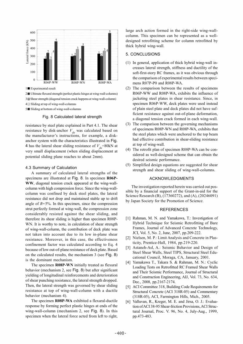
4.3 Summary of CalculationA summary of calculated lateral strengths of the
specimens are illustrated at Fig. 8. In specimen R06P-WW, diagonal tension crack appeared at the wing-wall-column with high compression force. Since the wing-wall-column was confined by deck steel plates, the lateralresistance did not drop and maintained stable up to driftangle of R=5%. In this specimen, since the compressionstrut perfectly formed at wing-wall, the compression zoneconsiderably resisted against the shear sliding, andtherefore its shear sliding is higher than specimen R08P-WN. It is worthy to note, in calculation of shear strengthof wing-wall-column, the contribution of deck plate wasnot taken into account due to its low in-plane shearresistance. Moreover, in this case, the effectivenessconfinement factor was calculated according to Eq. 4because of low out-of-plane resistance of deck plate. Basedon the calculated results, the mechanism 3 (see Fig. 8)is the dominant mechanism.
The specimen R08P-WN initially treated as flexuralbehavior (mechanism 2, see Fig. 8) but after significantyielding of longitudinal reinforcements and deteriorationof shear punching resistance, the lateral strength dropped.Then, the lateral strength was governed by shear slidingresistance at top of wing-wall-column with a ductilebehavior (mechanism 4).
The specimen R08P-WA exhibited a flexural-ductileresponse by forming perfect plastic hinges at ends of thewing-wall-column (mechanism 2, see Fig. 8). In thisspecimen when the lateral force acted from left to right,
large arch action formed in the right-side wing-wall-column. This specimen can be represented as a well-designed retrofitting scheme for column retrofitted bythick hybrid wing-wall.
5. CONCLUSIONS
In general, application of thick hybrid wing-wall in-creases lateral strength, stiffness and ductility of thesoft-first-story RC frames, as it was obvious throughthe comparison of experimental results between speci-mens R07P-P0 and R08P-WA.The comparison between the results of specimensR06P-WW and R08P-WA, exhibits the influence ofjacketing steel plates in shear resistance. Since, inspecimen R06P-WW, deck plates were used insteadof plain steel plate and deck plates did not have suf-ficient resistance against out-of-plane deformation,a diagonal tension crack formed in each wing-wall.The comparison between the governing mechanismsof specimens R08P-WN and R08P-WA, exhibits thatthe steel plates which were anchored to the top beamhad effective contribution in shear-sliding resistanceat top of wing-wall.The retrofit plan of specimen R08P-WA can be con-sidered as well-designed scheme that can obtain thedesired seismic performance.Simplified design equations are suggested for shearstrength and shear sliding of wing-wall-columns.
ACKNOWLEDGMENTS
The investigation reported herein was carried out pos-sible by a financial support of the Grant-in-aid for theScience Research (B), (17360272), and (A), (20246091)by Japan Society for the Promotion of Science.
REFERENCES
Rahman, M. N. and Yamakawa, T.: Investigation ofHybrid Technique for Seismic Retrofitting of BareFrames, Journal of Advanced Concrete Technology,JCI, Vol. 5, No. 2, June, 2007, pp.209-222.Nielsen, M. P.: Limit Analysis and Concrete in Plas-ticity, Prentice-Hall, 1984, pp.219-220.Astaneh-Asl, A.: Seismic Behavior and Design ofSteel Shear Walls, Steel TIPS, Structural Steel Edu-cational Council, Moraga, CA, January, 2001.Yamakawa T., Takara S. & Rahman, M. N.: CyclicLoading Tests on Retrofitted RC Framed Shear Wallsand Their Seismic Performance, Journal of Structuraland Construction Engineering, AIJ, Vol. 73, No. 634,Dec., 2008, pp.2167-2174.ACI Committee 318, Building Code Requirements forStructural Concrete (ACI 318R-05) and Commentary(318R-05), ACI, Farmington Hills, Mich., 2005.Valluvan, R., Kreger, M. E. and Jirsa, O. J.: Evalua-tion of ACI 38-95 Shear-friction Provisions, ACI Struc-tural Journal, Proc. V. 96, No. 4, July-Aug., 1999,pp.473-483.
Fig. 8 Calculated lateral strength
[1]
[2]
[3]
[4]
[5]
[6]
(1)
(2)
(3)
(4)
(5)
0
100
200
300
400
500
600
Late
ral f
orce
(kN
)
R06P-WW R08P-WN R08P-WA
Experimental resultUltimate flexural strength (perfect plastic hinges at wing-wall-columns)Shear strength (diagonal tension crack happens at wing-wall-column)Sliding at top of wing-wall-columnsSliding at bottom of wing-wall-columns
11
122 2
3
3 34
4
4
55
5
12345
-408-