cyclic furnace and high-velocity - nasa · pdf filenasa technical memorandum nasa fi x-2370...
TRANSCRIPT

NASA TECHNICAL
MEMORANDUM
NASA fi X-2370 c-h 1
CYCLIC FURNACE AND HIGH-VELOCITY OXIDATION OF AN ALUMINIDE-COATED HIGH-STRENGTH NICKEL ALLOY (B-1900)
by Stanley R. Levine
Lewis Resead Center
Cleveland, Olhio 44135
NATIONAL AERONAUTICS AND SPACE ADMINISTRATION l WASHINGTON, D. C. l SEPTEMBER 1971 d
https://ntrs.nasa.gov/search.jsp?R=19710026109 2018-05-24T15:26:42+00:00Z

TECH LIBRARY KAFB, NM
1. Report No.
_..--NASA-TM X-2370- ~~ I
2. Government Accession No.
_ .- ~~_. 4. Title and Subtitle
CYCLIC FURNACE AND HIGH-VELOCITY OXIDATION OF AN ALUMINIDE-C0ATE.D HIGH-STRENGTH NICKEL ALLOY pylgoo) _
7. Author(s)
Stanley R. Levine
9. Performing Organization Name and Address
Lewis Research Center National Aeronautics and Space Administration Cleveland, Ohio 44 135
12. Sponsoring Agency Name and Address
National Aeronautics and Space Administration Washington, D. C. 20546
15. Supplementary Notes -..-____.-
3. Recipient’s Catalog No.
5. Report Date September 1971
6. Performing Organization Code
8. Performing Organization Report No.
E-6301 10. Work Unit No.
129-03 11. Contract or Grant No.
13. Type of Report and Period Covered
Technical Memorandum 14. Sponsoring Agency Code
16. Abstract
The oxidation resistance of aluminide-coated B-1900 was studied in furnace tests at 980’ to 1150’ C (l- to 20-hr cycles) and in burner rig tests at 1040’ to 1150’ C (1-hr cycles). Metal- lographic data from the l-hour cyclic furnace tests indicated that a 40’ C increase in temper- ature caused a tenfold reduction in coating life while a cycle frequency change from 1 to 20 hours per cycle increased life several fold. The leading edge of the burner rig specimens showed coating degradation about twenty times as severe as comparable furnace tests at 1090’ C.
17. Key’Words (Suggested by Authoiis) )- ~. ~~ -..~
Coatings Superalloy Oxidation
19. Security Classif. (of this report1 -1 r-= 20 Security Classif. I
~~~ 18. Distribution Statement
Unclassified - unlimited
this page) ~1 21. No. of Pages 1 22. Price’
Unclassified I
Unclassified I
30 $3.00
* Far sale by the National Technical Information Service, Springfield, Virginia 22151
CYCLIC FURNACE AND HIGH-VELOCITY OXIDATION OF AN ALUMINIDE-
COATED HIGH-STRENGTH NICKEL ALLOY (B-1900)
by Stanley R. Levine
Lewis Research Center
SUMMARY
The oxidation resistance of a commercial aluminide coating on B-1900 was deter- mined in cyclic furnace and burner rig tests. Furnace tests were conducted at temper- atures from 980’ to 1150’ C using l- to 20-hour exposure cycles for times up to 400 hours. One-hour Mach 1 burner rig exposures were performed at average peak metal temperatures of 1040°, 1090°, and 1150’ C. Effects of temperature , cycle frequency, and burner rig exposure were primarily evaluated by weight change and metallographic data supplemented with X-ray diffraction, X-ray fluorescence, and electron microprobe analysis.
Aluminum depletion due to oxidation was the primary cause of coating breakdown. At temperatures below 1O9Oo C the coating-substrate reaction made a relatively small contribution to coating degradation. Depletion to a 30-micrometer nickel aluminum zone thickness was selected as the condition characteristic of general coating breakdown. At this point, the individual pNiAl grains were surrounded by gamma solid solution. Based on this criterion for coating breakdown, furnace tests indicated that a 40’ C increase in temperature caused a tenfold reduction in coating life. For l-hour furnace exposures, a life of 1000 hours was estimated at 1080’ C.
Cycle frequency changes in the furnace tests from 1 to 20 hours at 1040’ and 1O9Oo C increased the coating life by several times. The 20-hour cycles, however, produced little oxide penetration of the coating; thus, the scales spalled more readily on cooldown than did those formed during shorter cycles.
Burner rig exposure in a moderate erosion and thermal fatigue location caused a fourfold reduction in coating life, whereas hot gas and cooling air impinging normally (at the leading edge) at Mach 1 caused a twentyfold reduction in coating life compared to l- hour cycle furnace exposure at the same temperature.
INTRODUCTION
Superalloys are currently used in the combustor and turbine sections of aircraft gas-turbine engines. Metal temperatures in those sections generally range from 800’ to about 1000° C with hot spots reaching temperatures beyond 1100’ C. Modified aluminide coatings are employed on the superalloy components to obtain extended lifetimes in the oxidation-erosion-corrosion engine environment (ref. 1). The only certain way to estab- lish the life of a particular coating-superalloy system is to expose an actual part in the engine of interest under controlled test conditions. Such testing is extremely costly and must be reserved for only the most promising material systems. Likely candidates for engine tests are selected by a variety of screening tests aimed at simulating the critical conditions found in an engine.
Currently, there is little standardization of either the test procedures or of the failure criteria used in engine material screening tests. For this reason, considerable insight into coating degradation mechanisms is needed to interpret the results of various screening tests and to try to predict inservice behavior of a coating system on the basis of screening test data. To achieve such insight, carefully controlled furnace oxidation tests have been conducted in an effort to establish the influence of such exposure varia- bles as time, temperature, and exposure cycle frequency on the behavior of aluminide- coated cobalt alloy WI-52 (ref. 2). Tests at temperatures from 1040’ to 1150’ C for times to 608 hours and exposure cycles from 1 to 20 hours showed that aluminum deple- tion from the cobalt aluminide phase resulted in a replacement of the protective alumi- num oxide scale with cobalt aluminate and then cobalt chromate spinels. The amount of degradation increased with increasing exposure temperature, cycle frequency, and expo- sure time. In addition, the weight changes observed in l-hour cyclic furnace tests at 1090’ and 1150’ C were in substantial agreement with l-hour cyclic high-velocity burner rig test results conducted in the same study.
The purpose of the present study was to conduct a similar evaluation of the influence of furnace oxidation temperature, exposure time, and cycle frequency on the microstruc- tural, surface oxide, and weight change behavior of an aluminide coating on the cast high- strength nickel superalloy B - 1900. An additional purpose of this study was to determine how cyclic furnace test results compared to cyclic high-velocity burner rig test results and to establish estimates of coating life in these environments.
An examination was made of the changes which occurred in the aluminide coating on B-1900 during furnace exposure at temperatures from 980’ to 1150’ C for times up to 400 hours and exposure cycle frequencies from 1 to 20 hours. In addition, high-velocity burner rig tests were performed at average peak temperatures from 1040’ to 1150’ C and times to 380 hours using l-hour cycles. The effects of time, temperature, cycle frequency, and burner rig exposure were evaluated on the basis of weight and
2

microstructural changes. Limited X-ray diffraction, electron microprobe, X-ray flu- orescence, and selective color etching were also employed to establish the effects of the exposure variables on the composition and structure of the coating and oxide scale.
EXPERIMENTAL PROCEDURE
Materials
The alloy chosen for this study was cast nickel-base superalloy B-1900 with nominal composition by weight: 10 percent cobalt (Co), 8 percent chromium (Cr), 6 percent mo- lybdenum (MO), 6 percent aluminum (Al), 4 percent tantalum (Ta), 1 percent titanium (Ti), 0. 1 percent zirconium (Zr), 0.1 percent carbon (C), 0.015 percent boron (B), and the balance nickel (Ni). This alloy has been shown to be one of the most oxidation resist- ant turbine blade alloys (ref. 3).
Erosion bars, approximately 10 by 2.5 by 0.64 centimeter with a 30’ wedge along one long edge, were cast to shape and machined as shown in figure 1. Some bars were cut perpendicular to the length to produce small tab specimens approximately 0.3 centi- meter thick. Both bar and tab specimens were pack cementation coated by a vendor with a proprietary aluminide coating. All specimens were coated at the same time to reduce compositional variations.
The coated specimens had a silvery metallic appearance. A typical tab cross sec- tion of the as-received coating is shown in figure 2. The total coating thickness was about 80 micrometers (3 mils) on both erosion bars and tabs. The as-deposited coating was divided into four principal zones (Roman numerals), based on the distribution of intermetallic compounds.
Testing and Analysis
The aluminide-coated B-1900 coupons were cyclic furnace oxidation tested up to a maximum of 400 hours in air at temperatures of 980’ C (-1800’ F), 1040° C (-1900’ F), 1090’ C (-2000’ F), and 1150’ C (-2100’ F). At 980’ and 1150’ C, only l-hour cycles were used. At 1040’ and 1090’ C, cycle times of 1, 2, and 20 hours were employed. Time at temperature and the exposure time per cycle are presented as total hours at temperature (hours of exposure per cycle). For example, 400(2) indicates a total of 400 hours of exposure in a-hour exposure cycles. Tests were terminated at preselected times so that coating degradation could be followed as a function of time.
3

All furnace oxidation tests were conducted in vertical tube furnaces controlled to *8’ C. Air circulated through these furnaces by natural convection. The specimens were hung in platinum baskets and were rapidly inserted and removed from the furnace. Specimen weight changes were periodically determined during oxidation testing after al- lowing the specimen to cool to room temperature. The cool specimen was lightly brushed to remove loose scale and weighed to the nearest 0.1 milligram. Oxide spalls were collected periodically during the l-hour cyclic exposures (up to 100 hr), and these were examined under polarized light and by X-ray diffraction.
After completion of testing and visual examination, the specimen surfaces were ana- lyzed by X-ray diffraction using CuXc, radiation and a nickel filter. A limited X-ray fluorescence analysis was also performed.
Selected specimens were copper plated prior to metallographic preparation. Metal- lographic specimen cross sections were electrolytically etched with a 30 parts water, 30 parts glycerin, 30 parts hydrochloric acid, 10 parts nitric acid, and 1 part hydroflu- -oric acid mixture by volume to reveal the microstructure. Carbides and sigma phases were further revealed by immersion etching in an aqueous solution of 7 percent sodium hydroxide and 2.8 percent potassium permanganate or by heat tinting. Supplemental electron microprobe raster scans were performed on selected specimens. Strata and phases were identified in detail using data accumulated from all of the previous analytical techniques.
Erosion bar specimens were tested in sonic natural gas combustion products at av- erage peak metal temperatures of 1040°, 1090°, and 1150’ C. (See ref. 2 for further details. ) After each l-hour exposure at temperature the specimens were air blast quenched (below 100’ C in 1 min). Approximate weight changes were periodically recorded.
RESULTS
Characterization of the As-Deposited Coating
The as -deposited aluminide coating on B-1900 appeared to consist of four major zones. By combining the results of X-ray diffraction (XRD), X-ray fluorescence @RF), electron microprobe (EMP), and selective etching, the zones indicated in figure 2 were identified as described in the following paragraphs and as presented in table I.
The designation M in a compound represents one or more metals. For example, M in the carbide M23C6 is primarily chromium and M in the carbide M6C is primarily tita- nium. The designations P(NiAl) and y’(Ni3Al) are for phases with the respective struc- tures of these intermetallic compounds but which contain appreciable amounts of cobalt,
4

TABLE I. - SUMMARY OF MICROSTRUCTURAL CONSTITUENTS IN ALUMINIDE-COATED B-1900 - AS-COATED
AND AFTER CYCLIC FURNACE OXIDATION EXPOGURE
[After cyclic oxidation zones II and III (fig. 2) were less distinct and so are combined and identified as zone II (fig. 5). Therefore, as-coated zone IV becomes oxidized zone III, and the zone produced by interdiffusion between the coating and substrate becomes oxidized zone IV. ]
Zone
Oxide
I
II
III
IV
B-1900 substrate
Phases
‘y-A1203 Spine1 TiO2
f2-A1203 Cr2Al Ni2A13 P(NW
y’(Ni3N Y
M6C M23C6
PWM) y’(Ni3AU
7
M6C M23C6
MC 3(NiAl) hickness, Llm
PWW r’(Ni3Al)
1
M6C M23C6
MC
,“(Ni3Al) ?
M6C M23C6
MC c
),‘(Ni3Al) 1’
MC D
As -coated
J J J
J J
J
J
\’
J J J
J J J J
J J J J
-
After cyclic furnace oxidation exposure ;y~..._3:L-- 100
J
.- J
J
J J
J
J J
80
J
d
J :
J J
J J
J
:’
400(
J
J
J J
J J
J J
J J
72
J
J
J
J J
J J
J J J \’
lOO(1
J
J
J
;
J
J J
65
J
J J d
J J
J
J J J
400(l)
J
J
J J J
J
J J J
72
J
;
J
J J
:
400(20
J J
J
J J J
76
J J J
100(l)
J J
J
J J J
J
J J
66
J
400(l) 400(20)
J J J J
; J J
J V
-J J
J J J J J \i
38 46
J J
J J
J J J J
J J
J J J J J J J J
20(l) 100(l)
J J J J
J
J J J J
J J J
J J J J
vi 45 7
J J J
J J‘
J J J
J J
J J J J
: J J \’ J J
5
. . . .

chromium, and titanium and lesser amounts of other elements in addition to the principal constituents nickel and aluminum.
Qualitative concentration profiles from electron microprobe line scans used in the identification process are plotted in figure 3. The profiles are presented as counting rates of characteristic wave lengths relative to those of the pure element standards. Counts were averaged over arbitrary 7.5-micrometer increments and no attempt was made to correct for matrix effects. Because of the arbitrary size of the increments used in averaging the data, the correlation with microstructure is not exact. In general, the scans show decreasing aluminum content with depth from the outer surface of the coating. Concentrations of nickel and chromium fluctuate with position in the coating structure.
The outer zone (zone I) in figure 2 is about 24 micrometers thick and consists of ap- proximately equal quantities of a light and several dark etching phases with light phase forming a continuous outer skin, about 2 micrometers thick. This skin is rich in nickel, chromium, and aluminum. Based primarily on electron microprobe and X-ray fluores- cence data, the light etching phase was identified as Cr2Al and the darker etching phases were identified as primarily NiAl and Ni2A13. A line of coarse, dark etching particles is also present about midway through zone I. Selective immersion etching gave these par- ticles a blue tint indicating M23C6 carbides (ref. 4) rich in chromium, molybdenum, and tantalum. In addition, finer light brown particles were observed throughout this zone and all other zones in the coating when examined in the unetched condition. These particles were unaffected by the selective etch. Heat tinting oxidized these particles indicating that they were probably M6C carbides.
Zone II is approximately 4 micrometers thick and contains less chromium than zones I and III. It appears to consist of aluminum enriched nickel aluminide with some fine brown M6C carbide inclusions.
Zone III is approximately 40 micrometers thick. Electron microprobe raster and line scans revealed titanium enrichment of the outer 10 micrometers and tantalum enrich- ment of the inner 10 micrometers of this zone. Also, molybdenum concentration was at about the same level in the inner 10 micrometers of this zone as in the substrate. The continuous darker etching major phase in zone III is identified as aluminum enriched nickel aluminide. The included phases are M23 6 C carbides rich in chromium, titanium, molybdenum, and tantalum. The carbide concentration is particularly high in the inner 10 micrometers of zone III.
The diffusion zone (zone IV) consists of aluminum enriched y’(Ni3Al) in y(nicke1 terminal solid solution). Electron microprobe data show that molybdenum, tantalum, and titanium concentrations are at the same levels in zone IV as in the substrate, whereas the concentrations of the other elements gradually change through this zone to the same levels as found in the substrate. Selective etching revealed multicolored interdendritic MC car- bides penetrating this zone and blue M23C6 precipitates throughout the zone.
6

Furnace Oxidation Test Results
Weight change data for cyclic furnace oxidation tests at 980’ C are presented in fig- ure 4. Very small weight gains of 0.8 milligram per square centimeter or less were ob- served on the two specimens oxidized - one for lOO( 1) hours and the other for 400( 1) hours. The data approximate parabolic behavior and the agreement is good between the two specimens within the first 100 hours of testing. No visible coating failures were observed.
Figure 5 shows cross -sectional photomicrographs after the lOO( 1) and 400( 1) hour exposures at 980’ C. The microstructural constituents identified in these cross sections are summarized in table I. (Note that in figure 5 and subsequent photomicrographs of as- exposed coatings, the coating zone notation used is slightly different from that used for the as-deposited coating in figure 2. Zones II and III in figure 2 are less distinct in fig- ure 5 and so are combined and identified as zone II. Zone IV of figure 2 becomes zone III in figure 5. Also note, that the zone produced by interdiffusion between the coating and substrate is designated as zone IV in figure 5 and subsequent figures. )
The approximately 5-micrometer-thick surface oxide scale seen in figure 5 consisted primarily of alpha alumina ( a-A1203) as revealed by X-ray diffraction analysis of the spall (table II), by X-ray diffraction scans of the oxidized samples (table III), and by elec- tron microprobe raster micrographs, In addition, some nickel oxide (NiO) was detected by X-ray diffraction in the 40- and 60-hour spa11 samples. Several weak lines from un- identifiable phases were also detected. Visually, the spa11 consisted of fine white fluffy particles.
Zone I consisted of a mixture of high atomic number metallic and low atomic number oxide particles as born out by the respective light and dark areas on electron microprobe electron back scatter and sample current micrographs of the 100(l) hour sample. Signif- icant oxide penetration to a depth of 10 micrometers beneath the external scale was noted. Raster scans showed that the oxide particles were rich in aluminum and that sig- nificant aluminum depletion of the metallic particles of this zone had occurred. Also, zone I was richer in chromium and molybdenum than zone II. X-ray diffraction analysis of the coating and scale in situ revealed nickel aluminide as the major intermetallic phase. Alpha alumina and several weak lines corresponding to a sigma (0) phase similar to CrCo were also detected. The Ni2A13 and Cr2Al phases observed in the as-deposited coating were no longer present in detectable amounts. From these data and selective etching, the constitution of zone I of the lOO( 1) hour specimen (fig. 5(a)), exclusive of penetrating alumina, was M23C6 plus a smaller quantity of M6C in a P(NiAl) matrix. After 400(l) hours at 980’ C, coarsened M23C6 and M6C carbides were present in zone I (fig. 5(b)) along with P(NiAl) and r’(Ni3Al).
Zone II (fig. 5(a)) grew in thickness after 100(l) hours at 980’ C as a result of inter- diffusion between the initial three outer aluminum-rich coating zones and the substrate.
7
r: I
L
Exposure
time, hr
TABLE II. - X-RAY DIFFRACTION ANALYSIS OF OXIDE SPALL FROM
COATED B-1900 DURING CYCLIC FURNACE OXIDATION .-
1 2
4
10
20
40
60
80
100
f
Cl-AI203
I L I
aInsufficient sample for XRD powder pattern. bMinor phase not identifiable. ‘No sample collected.
Major Minor phase phase
(4 --- ---
Major phase
(Y-A1203
Minor phase
--- ---
(b) (b)
OJ) --
--- --
NiO (b)
NiO
(b)
(b)
Temperature, ‘C
1040
I
T 1090
Major
(cl
u-Al208 cl-A1203
a-Al208 Spine1 (8. 21)d
“-Al203 Spine1 (8. 10)
a-Al208 Spine1 (8.09)
cr-Al208 Spine1 (8.09)
a-Al208 Spine1 (8.09)
L
Minor phase
-- --
r Major phase
CY-A1203 CA.1203
CA1203 Ch4120Q
Spine1 (8. 1’ c4120~
Spine1 (8. 1
Ch4120Q Spine1 (8.0
CY -A1203 Spine1 (8.0
h41203 Spine1 (8.0
Ti02
/
‘
6)
1) --
Minor phase
NiO NiO
spine1 (8. 28)
(b)
Cr203
Cr203
Ti02
NiO Ti02
1
dLattice diameter in angstroms.
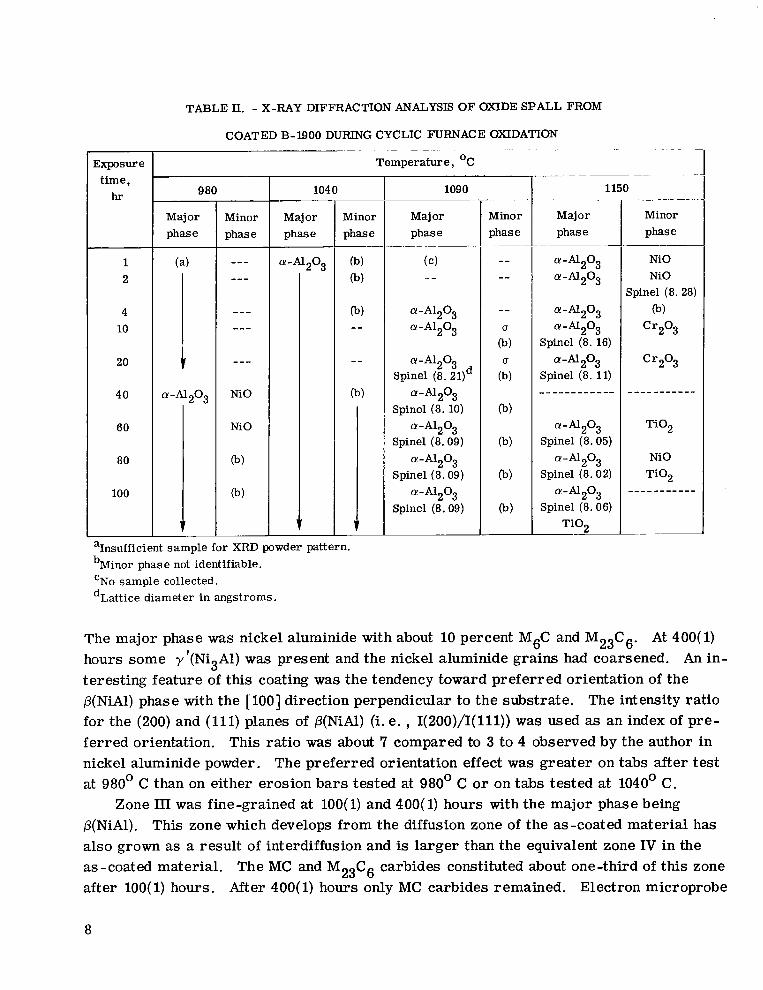
The major phase was nickel aluminide with about 10 percent M6C and M23C6. At 400(l) hours some v’(Ni3Al) was present and the nickel aluminide grains had coarsened. An in- teresting feature of this coating was the tendency toward preferred orientation of the P(NiA1) phase with the [ 1001 direction perpendicular to the substrate. The intensity ratio for the (200) and (111) planes of p(NiAl) (i.e. , 1(200)/1(111)) was used as an index of pre- f erred orientation. This ratio was about 7 compared to 3 to 4 observed by the author in nickel aluminide powder. The preferred orientation effect was greater on tabs after test at 980’ C than on either erosion bars tested at 980’ C or on tabs tested at 1040’ C.
Zone III was fine-grained at lOO( 1) and 400( 1) hours with the major phase being P(NiA1). This zone which develops from the diffusion zone of the as-coated material has also grown as a result of interdiffusion and is larger than the equivalent zone IV in the as-coated material. The MC and M23C6 carbides constituted about one-third of this zone after lOO( 1) hours. After 400(l) hours only MC carbides remained. Electron microprobe
8

raster micrographs showed that molybdenum, tantalum, and titanium remained concen- trated in zone HI with the tantalum and titanium apparently segregated in the carbide parti cles. These particles appear to be remnants of the consumed substrate grain boundaries.
The diffusion zone (zone IV) has not grown to an appreciable thickness after 400( 1) hours at 980’ C. The primary phase in this zone is y’(Ni8Al) with some y and MC and extensive penetration by acicular particles of a phase.
Weight change data for 1040’ C cyclic furnace oxidation are presented in figure 6. In this case, weight gains were observed for times up to 400(l) hours. Parabolic behav- ior is again approximated for the 400(l) specimens exclusive of spall. However, the weight gains reached 1.1 milligrams per square centimeter at 1040’ C as opposed to 0.8 milligram per square centimeter at 980’ C. Using 2-hour exposures, smaller weight gains were observed up to 200 hours. Twenty-hour exposures gave weight changes which oscillated between small positive and negative values with a net weight loss of 0.1 milli- gram per square centimeter at 400(20) hours. Specimen weight changes exclusive of spall appear to vary directly with cycle frequency.
Cross-sectional photomicrographs of some specimens oxidized at 1040’ C are pre- sented in figure 7. A significant effect of cycle frequency on oxide scale and depleted zone structure is apparent. In addition to forming a thin continuous outer oxide skin, the oxide (primarily cr-A1208) has penetrated through the depleted zone in specimens ex- posed to l-hour cycles (figs. 6(a) and (b)). The specimen exposed to 20-hour cycles (fig. 6(c)) showed a thicker oxide scale and considerably less oxide penetration into the depleted zone. Because of the penetration of oxide into the depleted zone at higher cycle frequencies the net retention of oxide is increased. This explains the observed direct dependence of weight gain on cycle frequency which is the opposite of the behavior pre- viously observed for coated WI-52 (ref. 2).
The primary oxide collected as spa11 from the 100(l) hour oxidation specimen was @-Al208 (table II). A trace of spine1 was detected in situ on samples oxidized for 400 hours (table HI). More spa11 particles having generally larger particle sizes were col- lected at 1040’ C than at 980’ C. The trend toward more spa11 particles of larger size as temperature increased was observed at 1090’ and 1150° C also.
As summarized in table III, zone I shifted from p + y’ as the major phases to y as the major phase between 20 and 100 l-hour cycles and between 100 and 200 2-hour cycles at 104OO C. Such a shift had not occurred after 400(l) hours at 980’ C (table III).
The grain growth process in the nickel aluminide layer (zone II) has not gone to com- pletion after 400 hours at 1040’ C. Occasional large grains spanning two-thirds to three- fourths of the zone are evident at 100 and 400 hours, respectively. Zone II showed less depletion after 400(20) hours than after 400(l) hours.
At 1040’ C the reaction between the coating and substrate proceeds slowly and is not a major contributor to the coating degradation process. Between 100 and 400 hours a
9

TABLE III. - IN SITU X-RAY DIFFRACTION ANALYSIS OF PHASES FORMED ON COATED B-1900 AFTER CYCLIC FURNACE OXIDATION
Sxposure time (cycle time),
hr
Temperature, ‘C
f f f
980 1040 1090 1150
Phases (lattice parameter, ii)
Phases (lattice parameter, W)
Phases (lattice parameter, d)
Phases (lattice parameter, A)
___---_____
____---____
___-_---_--
;I ----------- I
I
--_------mm
f
Major Minor Major Minor Major Minor Major
Cr203 a
Cr203 u
a-A1203 Spine1 (8.0’7)
a
cu-AlaO 0
cr-Al2O3 Spine1 (8.07)
c+A1203 Spine1 (8. 13)
Cy-A1203 Spine1 (8.08)
j o,Cr203
P(NiA1) (2.92 and 2.88)
cr-Al2O3
P(NiAU (2.89 and 2.87)
Y
a-Al203 0
cv-A1203 0
a-Al2O3 u
-------
wA1203 cr
c+A1203 0
a-A1203 u
0 Spine1
-------
-------
-------
-------
-------
20(l)
46(2) -------
lOO( 1)
lOO(2)
BMW (2.89)
__-____
lOO(20)
P(NW (2.88)
200( 1) Y
200(2) ------- Y
400(l) P(NiA1) wA1203 1 Y (2.88) a
400(20) ------- - - - - - - - Y
(Y-A1203
Y
cr-AlaO
Y Y
a-A1203
Y Y
Y
Y
CY-A1203 QI-A1203 I
Spine1 (8. 12) , I
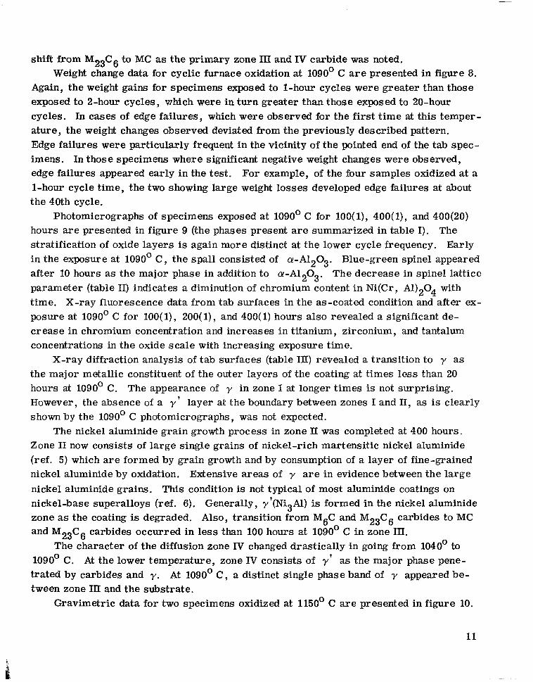
shift from M28C6 to MC as the primary zone III and IV carbide was noted. Weight change data for cyclic furnace oxidation at 1090’ C are presented in figure 8.
Again, the weight gains for specimens exposed to l-hour cycles were greater than those exposed to a-hour cycles, which were in turn greater than those exposed to 20-hour cycles. In cases of edge failures, which were observed for the first time at this temper- ature, the weight changes observed deviated from the previously described pattern. Edge failures were particularly frequent in the vicinity of the pointed end of the tab spec- imens . In those specimens where significant negative weight changes were observed, edge failures appeared early in the test. For example, of the four samples oxidized at a l-hour cycle time, the two showing large weight losses developed edge failures at about the 40th cycle.
Photomicrographs of specimens exposed at 1O9Oo C for lOO( l), 400(l), and 400(20) hours are presented in figure 9 (the phases present are summarized in table I). The stratification of oxide layers is again more distinct at the lower cycle frequency. Early in the exposure at 1O9Oo C, the spa11 consisted of cr-A1208. Blue-green spine1 appeared after 10 hours as the major phase in addition to cr-Al208. The decrease in spine1 lattice parameter (table II) indicates a diminution of chromium content in Ni(Cr, Al)204 with time. X-ray fluorescence data from tab surfaces in the as-coated condition and after ex- posure at 1090’ C for lOO( 1), 200( 1)) and 400( 1) hours also revealed a significant de- crease in chromium concentration and increases in titanium, zirconium, and tantalum concentrations in the oxide scale with increasing exposure time.
X-ray diffraction analysis of tab surfaces (table HI) revealed a transition to y as the major metallic constituent of the outer’layers of the coating at times less than 20 hours at 1090’ C. The appearance of y in zone I at longer times is not surprising. However, the absence of a y ’ layer at the boundary between zones I and II, as is clearly shown by the 1090’ C photomicrographs, was not expected.
The nickel aluminide grain growth process in zone II was completed at 400 hours. Zone II now consists of large single grains of nickel-rich martensitic nickel aluminide (ref. 5) which are formed by grain growth and by consumption of a layer of fine-grained nickel aluminide by oxldation. Extensive areas of y are in evidence between the large nickel aluminide grains. This condition is not typical of most aluminide coatings on nickel-base superalloys (ref. 6). Generally, r’(Ni8Al) is formed in the nickel aluminide zone as the coating is degraded. Also, transition from M6C and M28C6 carbides to MC and M28C6 carbides occurred in less than 100 hours at 1090’ C in zone III.
The character of the diffusion zone IV changed drastically in going from 1040’ to 1090’ C. At the lower temperature, zone IV consists of y’ as the major phase pene- trated by carbides and y. At 1090’ C, a distinct single phase band of y appeared be- tween zone III and the substrate.
Gravimetric data for two specimens oxidized at 1150’ C are presented in figure 10.
11

The large negative weight changes are associated with early coating failures and poor oxide scale retention.
Photomicrographs for 20( 1) and lOO( 1) hour specimens are presented in figure 11. (Phases present are summarized in table I. ) These photomicrographs show very little retention of surface oxide. The nickel aluminide grain growth process after 20 hours at 1150’ C is comparable to 400 hours at 1090’ C. However, zones III and IV have reached a more advanced state of degradation. Extensive dissolution of zone II and III carbides occurred after lOO( 1) hours of exposure.
Burner Rig Tests
Mach 1 burner rig tests were conducted at average peak metal temperatures of 1040°, 1090°, and 1150’ C. Weight change data are presented in figure 12. At 1040’ C the coating began to spa11 from leading and trailing edges at about 140 hours. At 240 hours extensive spalling of the coating occurred on one side of both specimens above and below the hot zone. Weight gains were observed up to 160 hours on one specimen and 260 hours on the other. In contrast, l-hour cyclic furnace oxidation (fig. 6) gave weight gains out to 400 hours. There is greater similarity between the weight change during 20- hour furnace cycles and l-hour burner rig cycles at this temperature. At 1090’ and 1150’ C only weight losses were observed in burner tests. Data for a bare B-1900 blade tested at 1090’ C are presented for comparison with the performance of the coated blades. Leading edge cracks were developed between 20 and 60 cycles in bare B- 1900. No cracks were observed in the coated blades until after 100 hours indicating that the coating im- proves the thermal fatigue crack resistance of B-1900. In furnace oxidation tests at 1090’ C, the coating displayed random behavior with the majority of the specimens devel- oping early coating failures at edges and negative weight changes at times less than 100 hours. Therefore, the overall agreement between furnace and burner rig weight change data at 1090’ C is good although one may easily be misled by a limited number of furnace tests. At 1150’ C, the weight changes in cyclic furnace and burner rig tests agree in that both tests gave large weight losses.
Photomicrographs of selected sections of a burner bar tested for 100 hours at a nom- inal temperature of 1090’ C are presented in figure 13. Because of the nature of the burner rig test, the temperature varies over a range of about 200’ C in the erosion bar sections generally sampled (fig. 1). Also, the severity of thermal shock and erosion varies from moderate on the large flat surfaces of the specimens to severe on the leading edge.
A 900’ C erosion bar section (not illustrated) showed little degradation. The coating structure of the 1040’ C erosion bar section after 100(l) hours (not illustrated) was com-
12

parable to the 100(l) and lOO(2) hour furnace exposures at 1040° C (fig. 7). However, the retained oxide scale was of comparable thickness to the 100(l) hour furnace test only. The 1080’ C section (fig. 13(a)) correlates very well with the 1090’ C, lOO( 1) hour fur - nace exposure (fig. 9) in all respects. Figure 13(b) shows a 1090’ C section. The coating in this location is in a state of degradation comparable to 400 hours of furnace exposure at 1090’ C (fig. 9). The final photograph (fig. 13(c)) is a section through the erosion bar leading edge which was exposed at a corrected optical pyrometer temperature of 1090’ C. The coating is clearly at a more advanced state of degradation than after the 1150’ C, 100(l) hour furnace exposure (fig. 11). Note the almost complete consumption of the P(NiAl) martensitic phase. Here thermal shock and erosion are the overwhelming factors in coating degradation, and these conditions are not adequately reproduced by cyclic fur- nac e oxidation.
DISCUSSION
From the results presented in the foregoing sections the effect of temperature, cycle frequency, and Mach 1 burner rig exposure on coating life will be estimated. A generally accepted model for coating breakdown has been proposed by Lindblad (ref. 6) and others. In this model, aluminum depletion leads to the breakup of the continuous nickel aluminide layer in the coating (zone II) into islands of p(NiAl) as was observed in this coating. Ox- idation of aluminum depleted regions (in this case y) proceeds more rapidly than oxida- tion of the p(NiAl) regions. Thus, oxide penetration and general coating breakdown oc- curs along aluminum depleted channels between nickel aluminide grains. Based on this model, the appearance of a zone II condition consisting of isolated islands of p sur- rounded by y was selected to be the inception of genera\ coating breakdown. More specifically, for this coating on B- 1900, this condition is associated with depletion of the nickel aluminide layer (zone II) to a thickness of 30 micrometers.
The effect of temperature in l-hour cyclic furnace tests was estimated from metal- lographic measurements on exposed specimens. Nickel aluminide (zone H) thickness was plotted against exposure time on log-log paper. At 1150’ C the time required to reach a 30 micrometer nickel aluminide (zone II) thickness was estimated by interpolation. At lower temperatures, the time required to reach this condition exceeded the longest test time. Thus, the reliability of coating life estimates decreases with decreasing temper- ature. The estimated lives are plotted against reciprocal absolute temperature in fig- ure 14. From these data it was estimated that a 40’ C increase in furnace exposure tem- perature causes a tenfold reduction in coating life. A furnace life of 1000 hours under l- hour cyclic test conditions was estimated at 1080’ C.
The effect of cycle frequency was estimated from extrapolation of P(NiA1) zone thickness data after 400 hours at 1040° and 1O9Oo C (appendix A). These calculations in-
13
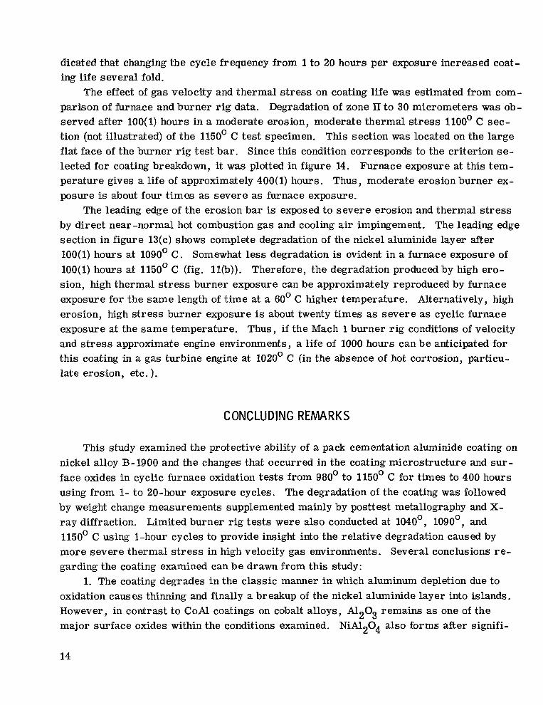
dicated that changing the cycle frequency from 1 to 20 hours per exposure increased coat- ing life several fold.
The effect of gas velocity and thermal stress on coating life was estimated from com- parison of furnace and burner rig data. Degradation of zone II to 30 micrometers was ob- served after 100(l) hours in a moderate erosion, moderate thermal stress 1100’ C sec- tion (not illustrated) of the 1150’ C test specimen. This section was located on the large flat face of the burner rig test bar. Since this condition corresponds to the criterion se- lected for coating breakdown, it was plotted in figure 14. Furnace exposure at this tem- perature gives a life of approximately 400(l) hours. Thus, moderate erosion burner ex- posure is about four times as severe as furnace exposure.
The leading edge of the erosion bar is exposed to severe erosion and thermal stress by direct near -normal hot combustion gas and cooling air impingement. The leading edge section in figure 13(c) shows complete degradation of the nickel aluminide layer after 100(l) hours at 1090’ C. Somewhat less degradation is evident in a furnace exposure of 100(l) hours at 1150’ C (fig. 11(b)). Therefore, the degradation produced by high ero- sion, high thermal stress burner exposure can be approximately reproduced by furnace exposure for the same length of time at a 60’ C higher temperature. Alternatively, high erosion, high stress burner exposure is about twenty times as severe as cyclic furnace exposure at the same temperature. Thus, if the Mach 1 burner rig conditions of velocity and stress approximate engine environments, a life of 1000 hours can be anticipated for this coating in a gas turbine engine at 1020’ C (in the absence of hot corrosion, particu- late erosion, etc. ).
CONCLUDING REMARKS
This study examined the protective ability of a pack cementation aluminide coating on nickel alloy B-1900 and the changes that occurred in the coating microstructure and sur- face oxides in cyclic furnace oxidation tests from 980’ to 1150’ C for times to 400 hours using from l- to 20-hour exposure cycles. The degradation of the coating was followed by weight change measurements supplemented mainly by posttest metallography and X- ray diffraction. Limited burner rig tests were also conducted at 1040°, 1090°, and 1150’ C using l-hour cycles to provide insight into the relative degradation caused by more severe thermal stress in high velocity gas environments. Several conclusions re- garding the coating examined can be drawn from this study:
1. The coating degrades in the classic manner in which aluminum depletion due to oxidation causes thinning and finally a breakup of the nickel aluminide layer into islands. However, in contrast to CoAl coatings on cobalt alloys, A1203 remains as one of the major surface oxides within the conditions examined. NiA1204 also forms after signifi-
14

cant coating degradation. Initial high aluminum compounds in the coating rapidly inter- diffused even at 980’ C while the M23C6 carbide and sigma phases in the coating only dis- solved at 1150’ C . At temperatures where the coating had useful life, that is below 1080’ C, the coating-substrate reaction made a small contribution to coating degradation.
2. Estimated cyclic furnace life based on the time for breakup of the nickel aluminide layer into separate grains 30 microns thick falls below 1000 l-hour cycles at temper- atures above 1080’ C. It is estimated that each 40’ C increase in exposure temperature causes a tenfold reduction in coating life in the range studied.
3. Increasing the furnace exposure cycle time from 1 to 20 hours resulted in a sev- eral fold increase in coating life based on the average of calculated upper and lower bound coating life estimates from metallographic data.
4. Burner rig exposure significantly shortened coating life as compared to furnace exposure. Locations experiencing moderate erosion and thermal stress conditions during l-hour burner-rig exposures experienced a fourfold reduction in life compared to l-hour cyclic furnace tests. Near normal hot gas and cooling air impingement on the burner specimen leading edge and the resultant thermal stress caused a twentyfold reduction in coating life relative to similar furnace tests. If the Mach 1 burner rig conditions of ve- locity and stress approximate engine environments, a life of 1000 hours in a gas turbine engine could be anticipated for this coating on B-1900 at 1020’ C.
5. Nickel aluminide zone thickness and the time to breakup of the nickel aluminide layer are more reliable indicators of coating degradation than weight change.
6. Furnace weight change data gave misleading results. In contrast to the decrease in the nickel aluminide layer thickness with increasing cycle frequency at 1040’ and 1090’ C, the weight gains were higher for shorter cycle times. This occurred because at the shorter cycle times more internal oxidation and oxide penetration developed making the resulting surface scale less prone to spallation than the scale that developed during longer exposure cycles.
Lewis Research Center, National Aeronautics and Space Administration,
Cleveland, Ohio, June 14, 1971, 129 -03.
15

APPENDIX A
DETERMINATION OF THE EFFECT OF CYCLE TIME ON COATING LIFE
IN CYCLIC FURNACE TESTS
Upper and lower bounds on 20-hour cyclic coating life at 1040’ and 1090’ C are esti- mated by extrapolation of nickel aluminide zone thickness data after 400 hours of furnace exposure. A lower bound on the life of the coating was estimated by assuming that expo- sure time only is important beyond 400 hours and that cycle time has no effect beyond 400 hours of exposure. An upper bound was set by assuming that coating life only de- pends on the number of exposure cycles beyond 400 hours of exposure with the severity of each cycle weighed according to a parabolic oxidation law. Data are taken from table I and figure 14. The symbols used are defined as follows:
coating life, hr
cycle time, hr
coating life, cycles
consumable nickel aluminide zone thickness, ,um (NiAI zone thickness - 30 pm)
consumable nickel aluminide zone consumption rate, pm/cycle or pm/hr
Case I
Assume coating life depends on exposure time beyond 400 hours only - a lower bound. Then,
iu, = iw
At 1090’ C ,
Z(1) = 600 hr, x(1) = 81.1, x(20) = 16~
AZ (1) = 600 - 400 hr
;((I) = x(l) - 8 p/k --- AZ(l) 200
16
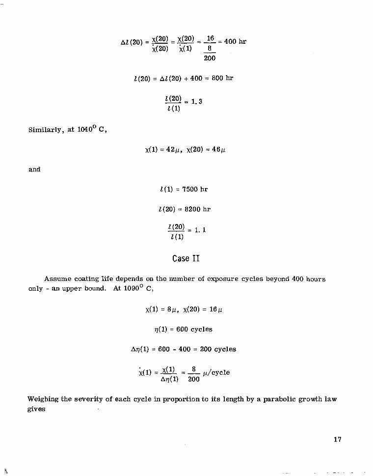
AZ (20) = x(20) - x(2O) - l6 - 400 hr --- --- i(W i(l) 8
200
Z(20) = AZ(20) + 400 = 800 hr
1(20)= 1.3 Z(l)
Similarly, at 1040° C ,
x(1) = 421.1, x(20) = 46y
and
Z(1) = 7500 hr
Z(20) = 8200 hr
1(20)= 1.1 Z(l)
Case II
Assume coating life depends on the number of exposure cycles beyond 400 hours only - an upper bound. At 1090’ C,
x(l) = 8p, x(20) = 16~
q(l) = 600 cycles
Aq(1) = 600 - 400 = 200 cycles
;(( 1) = x(1) - 8 &cycle --- Aq(l) 200
Weighing the severity of each cycle in proportion to its length by a parabolic growth law gives
17
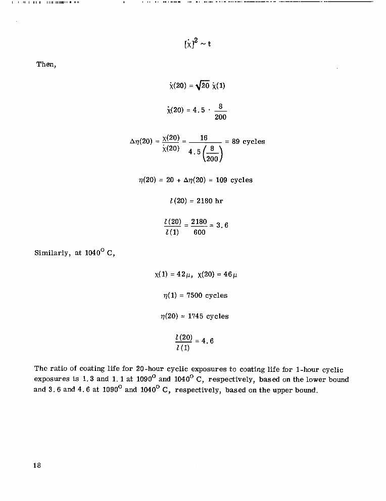
Then,
i(20) = fi i(l)
$20) =4.5 - 8 200
= 89 cycles
$20) = 20 + A77(20) = 109 cycles
Z(20) = 2180 hr
z(20) - 2180 - 3. 6 Z(l) 600
Similarly, at 1040° C,
x(1) = 421-1, x(20) = 46~
q( 1) = 7500 cycles
~(20) = 1745 cycles
10~4.6 Z(l)
The ratio of coating life for 20-hour cyclic exposures to coating life for l-hour cyclic exposures is 1.3 and 1.1 at 1090’ and 1040’ C, respectively, based on the lower bound and 3.6 and 4.6 at 1090’ and 1040’ C, respectively, based on the upper bound.
18

REFERENCES
1. Puyear, R. B. : Oxidation and Sulfidation Resistant Coatings for Superalloys. Paper 690479, SAE, May 1969.
2. Grisaffe, Salvatore J. ; Deadmore, Daniel L. ; and Sanders, William A. : Furnace and High-Velocity Oxidation of Aluminide-Coated Cobalt Superalloy WI-52. NASA TN D-5834, 1970.
3. Johnston, James R. ; and Ashbrook, Richard L. : Oxidation and Thermal Fatigue Cracking of Nickel- and Cobalt-Base Alloys in a High Velocity Gas Stream. NASA TN D-5376, 1969.
4. Goward, G. W. ; Boone, D. H. ; and Giggins, C. S. : Formation and Degradation Mechanisms of Aluminide Coatings on Nickel-Base Superalloys. Trans. ASM, vol. 60, no. 2, June 1967, pp. 228-241.
5. Smialek, James L. : Martensite in NiAl Oxidation-Resistant Coatings. Metallurg. Trans. , vol. 2, no. 3, Mar. 1971, pp. 913-915.
6. Lindblad, N. R. : A Review of the Behavior of Aluminide-Coated Superalloys. Oxidation of Metals, vol. 1, no. 1, Autumn 1969, pp. 143-170.
---) -0.63
Approximate temperature profile
Figure 1. - Cast B-1900 burner rig specimen and temperature profile for nominal 1090’ C run. A, B, and C correspond to metallographic sections in figure l3. All linear dimensions are in centimeters.
II
19

Figure 2. - Coated B-1900 as-received. Etch% 20 water, M glycerin, 10 nitric acid, 5 hydrofluoric acid by volume.
Coating B -1900
2 Zone .I II III IV Substrate
1 I I I
i Molybdenum I ’ ’ I I I I
E I 5 0 __I Cobalt
Ti I I I I
.6
.4
’ ‘2 ~~~ Aluminulm
0 20 40 60 80 100 Distance from surface, pm
Figure 3. - Electron microprobe line scans of as-coated B -1900.
20

Ei &u
l-
55 E2l .5? E p 0 100 200 300 400
Exposure time, hr
Figure 4. - Weight changes for coated B-1900 in cyclic furnace oxidation. Air, 98@ C; l-hour cycles.
la) Exposure time, 100 (1) hours,
. j v_ . ‘, C-71 -2155
(b) Exposure time, @.I (1) hours.
Figure 5. - Coated B-1900 after cyclic furnace exposure at 980’ C.
Copper plating Z-Oxide
I
B-1900
Mount -z-- Oxide -
B-1900
21

2 0 1-hr cycles
-2 0 2-hr cycles u
P
A 20-hr cycles
1
d 5 5 z 0 .F is
200 Exposure time, hr
Figure 6. - Weight changes for coated B-1900 in cyclic furnace oxidation. Air, 104Cf C.
22

B-l’%0
(a) Exposure time, 100 (1) hours.
.., _i’ : _.._( :’ :’ .a ,” ,_, : :.
‘x250;’ ..tc.
. . 1, . . . . ._.,.a _;.’ :, ._, ,.a ,-. ‘. ,. :c ., I ,. .,
(bl Exposure time, 400 (1) hours.
Mount =-Oxide I
II
B-1900
(c) Exposure time, 400 (2) hours.
Figure 7. - Coated B-1900 after cyclic furnace exposure at 1040’ C. Reduced 15 percent in printing.

5-
6-
0 I-hr cycles 0 2-hr cycles A 20-hr cycles
100 200 Exposure time. hr
J 300 400
Figure 8. - Weight changes fo; coated B-1900 in cyclic furnace oxidation. Air, 1090' C.
24

Mount =-Oxide I -
II
-
III - - I”
B-1900
(a) Exposure time, 100 (1) hours.
(bl Exposure time, 400 (1) hours.
(c) Exposure time, 400 (201 hours.
Figure 9. - Coated B-1900 after cyclic furnace oxidation at 1090” C. Reduced 15 percent in printing.
25
--

Exposure time, hr
Figure 10. - Weight changes for coated B-1900 in cyclic furnace oxidation. Air, llsO” C; l-hour cycles.
(a) Exposure time, 20 (1) hours.
Copper plating 1 Oxide I -
II -
III -
IV
B-1900
Mount z--Oxide I -
II
-
III
-
IV
B-1900
lb) Exposure time, 1Kl (1) hours.
figure 11. - Coated B-1900 after cyclic furnace oxidation at 11%” C.

-
0 iO4@ C coated A 1098 C coated v 1098 C bare (13 llW C coated
^^^ 400 mu 200 Exposure time, hr
Figure 12. - Mach 1 burner-rig weight change data for bare and coated B-1900 USinY l-hour Cycles.
27

Mount - _ Oxide
I -
II
-
III
IV
i-1900
ta) Moderate temperature zone, 1080 C.
rbl Hot zone, 1090 C.
(cl Leading edge, 1090 C
Figure 13. - Coated B-1900 after 100 (II hours of Mach I burner-rig exposure at 1090 C nominal temperature. Reduced 27 percent in printing.
Mount -Oxide -
I
-
III
IV
-
B-1900
28

I- ---.
l/T, K
1150 1090 1040 Temperature, ‘C
980
Figure 14. - Effect of exposure conditions on life of coated B-1900.
NASA-Langley, 1971 - 17 ~-6301

NATIONAL AERONAUTICS AND SPACE ADMISTRATION
WASH I NGTON. D.C. 20546 POSTAGE AND FEES PAID
OFFICIAL BUSINESS NATIONAL AERONAUTlCS AND
FIRST CLASS MAIL SPACE ADMlNlsrRATION PENALTY FOR PRIVATE USE 1300
014B 01 C2 UL 37'730930 S00903DS 720401 DIZPT OF TEE A.13 FORCE AF SYSTEHS COWIAND BP WEAPONS .LAB (WLOL) ATTN: E LOO BOWflAN, CHIEF TECH LIBRARY KXRTLAND ?iFB PI!! 87117
POSTMASTER: If Undeliverable (Section 158 Posral Manual) Do Nor Rerurn
“The aeronautical and space activities of the United States shall be conducted so-as to contribute . . . to the expansion of human Ln~wl- edge of phenomena in the atmosphere and space. The Administration shall Provide for rhe widest practicable and appropriate dissemindtion of information concerning its activities and the results thereof.”
-NATIONAL AERONAUTICS ANDSPACE ACTOF 1958
NASA SCIENTIFIC AND TECHNICAL PUBLICATION’S ,
.; . . TECHNICAIj’REPORTS: Scientific and technical information considered important, complete, and i lasting contribution to existing knowledge. * I
TECHNICAL NOTES: Information less broad in scope but nevertheless of importance as a contribution to existing knowledge.
TECHNICAL MEMORANDUMS: Information receiving limited distribution because of preliminary data, security classifica- tion, or other reasons.
TECHNICAL TRANSLATIONS: Information published in a foreign language considered to merit NASA distribution in English.
SPECIAL PUBLICATIONS: Information derived from or of value to NASA activities. Publications include conference proceedings, monographs, data compilations, handbooks, sourcebooks, and special bibliographies.
TECHNOLOGY UTILIZATION PUBLICATIONS: Information on technology used by NASA that may be of particular
CONTRACTOR REPORTS: Scientific and technical information generated under a NASA contract or grant and considered an important contribution to existing knowledge.
interest in commercial and other non-aerospace . . npphcatlons. Pubiications include Tech Briefs,
Technology Utilization Reports and l’echnology Surveys.
Details on the availability of these public&ions may be obtained from:
SCIENTIFIC AND TECHNICAL INFORMATION OFFICE
NATIONAL AERONAUTICS AND SPACE ADMINISTRATION Washington, D.C. PO546