cyclic behavior of a hybrid anchoring device enhancing the
TRANSCRIPT

Journal of Civil Engineering Research 2013, 3(1): 52-63 DOI: 10.5923/j.jce.20130301.06
Cyclic Behaviour of a Hybrid Anchoring Device Enhancing the Flexural Capacity and Ductility of an R/C
Bridge-Type Pier Strengthened with CFRP Sheets
G. C. Manos*, K. Katakalos, V. Kourtides
Laboratory of Experimental Strength of Materials and Structures, Dept. of Civil Engineering, Aristotle University, Thessaloniki, Greece
Abstract Fibre-reinforced polymer (FRP) composites have been extensively investigated during the last years as an alternative means of strengthening reinforced concrete structural elements. One of the difficult ies of applying such strengthening schemes in pract ice is the effective anchorage of such FRP components (layers, etc.). The present investigation examines the development of a Hybrid Anchoring Device (HAD) and its application to a specimen representing a scale model of a joint of a bridge-type reinforced concrete pier with its foundation. The objective here is to enhance the flexural capacity and the ductile behaviour of such a specimen by externally applying carbon fiber-reinforced polymer sheets together with the HAD in order to transfer the forces from CFRP sheets to the foundation. This pier specimen is subjected at the top to a pseudo-dynamic horizontal displacement cyclic loading sequence together with the simultaneous application of a constant vertical load. The behaviour observed experimentally is presented and discussed. Furthermore, this paper includes the most important findings of a supplementary numerical investigation, using the FEA software ABAQUS, aimed to study the behaviour of the HAD prior to its manufacture. Finally, the numerical investigation is extended to simulate the behaviour of the test pier specimen with the HAD attached to its foundation. Both the numerical and the experimental behaviour demonstrate that the applied HAD resulted in a 100% increase in the flexural capacity of the pier specimen and a 50% increase in its overall energy absorption capability. The anchoring device has been patented with No WO2011073696.
Keywords Hybrid Anchoring Device, Cyclic Behaviour, Reinforced Concrete, Bridge Pier, Numerical Simulations, Ductile Behaviour, Flexural strengthening, Carbon Fiber Reinforced Polymers
1. Introduction Many R/C structures need strengthening either because
they were built according to old seismic codes and do not meet the requirements of new codes, or they are damaged after a strong earthquake sequence and they need repair and strengthening. One of the basic parameters of strengthening employing FRP layers externally is the efficient anchorage of these polymer sheets to the concrete parts for the desired transfer of the tensile forces that develop on these layers. Thus the satisfactory behaviour of the anchorage scheme becomes of outmost importance because the FRP layers by themselves can withstand a high level of tensile forces. Thus an effective anchorage of the FRP can be used to utilize the strengthening potential of such FRP layers and to delay the eliminat ion o f the FRP layers strengthen ing contribution that would result from the premature failure of
* Corresponding author: [email protected] (G. C. Manos) Published online at http://journal.sapub.org/jce Copyright © 2013 Scientific & Academic Publishing. All Rights Reserved
their anchoring. (i.e . debonding) There is a real necessity to develop various reliable
anchoring details that can accompany repair and strengthening schemes of Reinforced Concrete elements employing FRP’s in such a way that the FRP parts and their anchoring detail together can provide a feasible solution combin ing the high tensile strength of the FRP material and the relative easy form of application. When fiber reinforced polymer sheets are bonded to the tension face of an R/C member with the use of a structural epoxy resin, the most common type of failure is the delaminating of the FRP sheets from the structural member. Numerous researchers [1-4, 16-20] have conducted experiments to study this delaminating type of failure and to investigate means for improvement. When the R/C member is a beam subjected to flexure it was shown that the flexural capacity o f this member is increased when this delaminating of the FRP sheet type of failure is delayed. T. El Maaddawy and K. Soudki (2007)[5] showed that utilizing mechanical anchors one can rely less on the bond provided by the use of the epoxy resin. They conducted a series of experiments with unbounded FRP strips and they used a system which

Journal of Civil Engineering Research 2013, 3(1): 52-63 53
consisted of mechanical anchors, at the two edges of the beam, as a means of anchoring the FRP sheet in tension to the R/C beam. In th is way, the tested beams were much less likely to develop any delaminating of the FRP type of failure up to their u ltimate flexural capacity. A. Lamanna, L. C. Bank and D. W. Scott (2004)[6] studied the anchoring of FRP sheets on R/C elements by means of mechanical anchors spaced at certain intervals. They showed that smaller bo lts with close spacing have better behaviour than big bolts with longer spacing. They also demonstrated that this type of attachment of FRP sheets on R/C members requires less time than the usual method of bonding with epoxy resin. J. H. Lee, M. M. Lopez and C. Bakis (2007)[7] conducted extensive research on bonding FRP’s using mechanical fasteners. The mechanical fasteners were used instead of the epoxy resin for bonding FRP to the concrete. They showed that this type of attachment leads to a mode of failure accompanied with the crushing of the concrete during gradual FRP delaminating. As a result the R/C beam becomes more ductile especially when the fasteners are placed near the ends. The behaviour of mechanical fasteners, as a method of attachment, was investigated under fatigue and cyclic loading by M. Ekenel, A. Rizzo, J. J. Myers, A. Nanni (2006)[8]. They demonstrated that the fatigue life of the test specimens was increased. A recent contribution by Nagaraj Eshwar, Antonio Nanni, and Timothy James Ibell (2008)[9] includes the comparison of two anchoring systems that can be used to improve the performance of a strengthening scheme, which consists of anchoring FRP laminates with FRP spikes and with near surface mounted (NSM) end anchors. They concluded that the anchoring of the FRP laminates is very important as it can result in the improvement of the strengthening process. They finally suggest the decrease of the knock down factors Kv and Km introduced by ACI 440.2R [2].
All the above research deals with the attachment of FRP sheets to individual R/C members, and in particular reinforced concrete beams under flexure. However, it is very important to investigate the possibility of applying such externally applied FRP sheets on structural assemblies that include more that one element, horizontal as well as vertical and their joint, e .g. beam to column or column to its foundation footing. J.D. Hall, P.M. Schuman and H.R. Hamilton III (2002)[10] conducted an investigation on the development of a ductile anchorage system for strengthening un-reinforced masonry with FRP’s. Although their research effort dealt with un-reinforced masonry walls, the problem of anchoring FRP sheets remains the same as for R/C structural elements. They developed a system combin ing the FRP sheets bonded with epoxy resin with anchoring steel plates and mechanical fasteners. The tested models developed several modes of fa ilu re such as delaminating of FRP, rupture of FRP, and yielding of the steel plate. The y ield ing of the steel p late is desirable as it provides a relatively ductile component in the investigated strengthening with FRP scheme. F. Colomb, E. Ferrier and P. Hamelin (2007)[11] investigated the use of anchors made
of the same material as the strengthening scheme with polymers. They manufactured CFRP fabric rollers which they embedded into the foundation footing of an R/C column-foundation joint and bonded them with epoxy resin. It was demonstrated that in most cases the failu re occurred due to the fracture of these FRP anchors.
The present investigation deals with a similar problem; that is to transfer the tensile forces from an externally applied FRP sheet on a vertical R/C member undergoing flexure to its foundation footing. This was attempted by a strengthening scheme combining the FRP sheet, that was externally attached to the R/C vert ical member with both epoxy resin and steel bolts, with a hybrid anchoring devise (HAD) made of steel as will be described in detail.
2. Preliminary Design of HAD 2.1. Numerical Simulation
At this preliminary design stage the HAD was in itially developed through a parametric numerical simulation which is eventually supplemented by specific tests with pilot HAD specimens. It should be noted that the developed numerical models are rather crude since they aim to extract the basic structural response of the proposed HAD, which are further studied experimentally. Figure 1 depicts the main outline of the device. It consists of two vertical steel bolts that support a horizontal cylindrical steel rod. The largest portion of the vertical steel bolts below the horizontal rod has sufficient length and shape to be effectively embedded within the volume of the R/C foundation. The horizontal steel rod is utilized to facilitate the wrapping of FRP layers around it. Both wings of these FRP layers wrapped around the steel rod become one sheet that is next attached, with the use of epoxy resin and anchor bolts, on to the side of the R/C pier specimen to a sufficient length.
Figure 1. HAD and its typical deformed shape

54 G. C. Manos et al.: Cyclic Behaviour of a Hybrid Anchoring Device Enhancing the Flexural Capacity and Ductility of an R/C Bridge-Type Pier Strengthened with CFRP Sheets
The limit state that concerns the debonding of FRP layers from the side of the pier specimen is experimentally controlled through this specific attachment technique and the attachment length; as a result it is not investigated further in this section. Furthermore the vertical steel bolts are assumed to have sufficient embedment details as to provide the required resistance against the limit state that leads to the pull-out of these bolts from the concrete foundation. Thus, excluding the debonding of the FRP layers from the side of the specimen and the pulling out of the embedded vertical steel bolts, the remain ing failu re modes that are considered in the parametric investigation are threefold. The first mode is the yield ing and eventual fracture of the vertical steel bolts at the portion that lies between the foundation and the horizontal rod. Any other type of failure of the connection between the vertical bolts and the steel rod is excluded. The second mode of failu re is the yield ing of the steel horizontal rod and the third and last mode of failu re is the fracture of the FRP sheet which is wrapped around the horizontal rod.
A FEA commercial program, ABAQUS, is used for the parametric numerical simulation utilizing 3D fin ite elements. The horizontal rod is assumed to be made of mild steel with yield stress equal to 360Mpa, whereas the vertical bolts are assumed to be made of high yield point steel (550Mpa). In any case the same type of investigation can be easily repeated with alternative material properties.
Thus the parametric investigation focuses on the following specific parameters that are directly connected with the HAD. These are:
a) the width and thickness of the FRP layers that are wrapped around the horizontal steel rod,
b) the span and the diameter of the horizontal rod and c) the length and the diameter of the portion of the
vertical bolts that lies between the foundation and the horizontal rod.
All the parameters ment ioned in the a), b), c) above are
varied within certain practical limits in order to investigate the sensitivity of the behaviour of the HAD to their variation. Of the outmost interest is how the variation of these parameters (a,b,c above) in fluences the post-elastic behaviour and the prevailing mode of the HAD.
A tri-linear constitutive material low is assumed for the mild steel and the high y ield strength steel whereas the FRP layers are assumed to be made of carbon and to behave elastically t ill a fracture limit stress. The corresponding values for the constitutive laws of each one of these three materials, which were assigned in this particular software, are listed (Table 1).
Figure 1 shows a typical HAD geometry with a horizontal rod having a total length equal to 280mm and a diameter of 40mm. The vertical steel bolts have a diameter of 18mm. As mentioned before, this is an init ial geometry with certain parameters varied through the parametric numerical investigation.
The numerical investigation assumed, as well, that the bottom ends of the vertical steel bolts are fu lly fixed. Moreover, the connection between the horizontal rod and the vertical steel bolts was assumed to be monolithic. The loading was imposed as a prescribed uniform vertical displacement pattern at the full length of the upper part of the CFRP sheet. As a result, the CFRP is subjected to tension whereas the horizontal rod undergoes flexure. The contact surface between the CFRP sheet and the horizontal rod is considered as frictionless; thus the CFRP sheet can slip or move independently from the rod. The fact that several coefficients of friction did not change the results significantly was investigated since the loading condition was an imposed vertical d isplacement. Also during the preparation of the pilot HAD specimens (see next section) lubricating oil was utilized to approximate this condition of almost friction less contact surface between the horizontal rod of the HAD and the CFRP sheet.
Table 1. Material properties of HAD’s parts
Part of HAD Modulus of Elasticity (Mpa) Yield stress (Mpa) Ultimate stress (Mpa)
Horizontal Steel Rod 200000 360 396 Vertical Steel Bolts 200000 550 650
CFRP Sheet 500000 - 5500
Table 2. HAD with uniform diameter of the horizontal steel rod
Studied variable Value of variable parameter
Applied Total Axial Load (kN) No. CFRP layer Limit Displacement (mm)
Leading to failure Mode of failure
(1) (2) (3) (4) (5) (6) rod’s diameter
(rod’s span 280mm) (CFRP’s width 200mm)
40mm 168 4 1.2 CFRP rupture 30mm 119 4 1.0 CFRP rupture 20mm 55 4 0.87 CFRP rupture
rod’s span / CFRP’s width (rod’s diameter 40mm)
380mm / 200mm 131 4 2.5 CFRP rupture 380mm / 300mm 180 4 1.5 CFRP rupture 200mm / 120mm 217 4 2.5 CFRP rupture
rod’s diameter (rod’s span 280mm)
(CFRP’s width 200mm) 40mm / 30mm / 20mm 622 / 368 / 158 15 / 9 / 5 30 / 20 / 20 Rod yielding

Journal of Civil Engineering Research 2013, 3(1): 52-63 55
A large number of parametric numerical simulations have been conducted. Tables 2 and 3 present the most important numerical models that were employed to study the HAD’s behaviour. They are categorized according to the investigated variable, which is listed in the rows of the first column. For the numerical simulations that correspond to each one of the main rows of Tables 2 and 3, the values of the corresponding variable are changed as listed, whereas the values of all the other parameters remain constant (with italics in the 1st column of Tab le 2) as defined in the init ial geometry; that is a horizontal rod with a length of 280mm (235mm from the supports), and a CFRP layer of thickness 0.7mm (4 layers) with a length of 180mm. The typical geometry of the vert ical steel bolts is of 18mm d iameter and 70mm length. A typical deformed shape of the numerical model of the HAD under the imposed displacement pattern is depicted in Figure 1.
In the first row of Table 2 the variable parameter is the diameter of the horizontal rod from 40mm to 20mm. Figures 2a,b,c depict the axial stress distribution for the CFRP sheet wrapped around the horizontal steel rod. As expected, the bigger the d iameter of the horizontal rod the smaller the curvatures it develops along its axis leading to a more uniform axial stress distribution for the CFRP sheet, as shown by the white line diagram that represents the axial stress distribution on a cross section 40mm from the axis of the rod. It was assumed that a strain of 1.1% resulted in the failure of the CFRP sheet.
In the second row of Table 2 the variable parameters is the ratio of the CFRP sheet width over the length of the horizontal steel rod. As can be seen, when this ratio is increased from an in itial value corresponding to the typical geometry, this leads to a less uniform axial stress distribution and consequently to a relatively p remature fracture of the CFRP sheet. This is again due to the fact that a relatively flexib le rod develops larger curvatures along its axis thus influencing the corresponding axial stress distribution of the CFRP sheet. From the above observations it can be further concluded that it is not desirable to have a steel rod, either of relatively small diameter o r large span, which develops large curvatures at the part where the CFRP sheet is wrapped around it. At the same time, horizontal rods with relat ively large diameter and small span perform in elastic state of stress leading the HAD to develop either fracture of the CFRP, which also remains almost elastic up to its fracture, or leading to the yielding o f the vert ical steel bolts; the latter present a possible plastic mode of failure as will be discussed next. The resulting non-uniform d istribution of the axial stress for the CFRP sheet for relat ively large curvatures of the horizontal rod was accompanied by a decrease in the bearing capacity of the HAD in terms of limit imposed displacement (column 6 of Table2) and applied total axial load (column 3 Tab le2).
At this point it should be ment ioned that for the current investigation the longitudinal shear strains were relat ively small (≈ 1.2∙10-4), which led to the adoption of a rather
simplified failure criterion based on the longitudinal strains. For other more complex applicat ions a more sophisticated failure criterion could be included in the future which will not neglect the possibility of shear splitting failure.
Figure 2. Distribution of axial membrane stresses
In the third row of Table2, the thickness of the CFRP sheet was increased to 2.63mm (15 layers) in order to lead the HAD into the yielding mode of the horizontal steel rod. As was expected, the smaller diameter rod resulted in much smaller yielding load for the HAD; however, in all these cases with the yielding of the horizontal rod, the limit total axial load (column 3 of Table 2) attained values larger than the corresponding values for all the previously investigated cases (rows 1 and 2) where the mode of failure developed due to the fracture of the CFRP sheet. Moreover, the obtained load-displacement behaviour of the HAD with the yielding rod, exh ib ited post-elastic trends that represent a desirable feature of the HAD’s performance. Consequently, from all these findings of the numerical investigation it became obvious that the numerical performance o f a HAD with a variab le diameter, as shown in Figure 3a, should be examined next. The in itial HAD numerical investigation was supplemented with an additional numerical HAD model with variab le diameter, depicted in Figure 3a.
Figure 3a. HAD-Variable diameter
Figure 3b. Deformed shape
This HAD model had a horizontal rod with two specific regions; the region near the vertical steel bolts was made
56 G. C. Manos et al.: Cyclic Behaviour of a Hybrid Anchoring Device Enhancing the Flexural Capacity and Ductility of an R/C Bridge-Type Pier Strengthened with CFRP Sheets
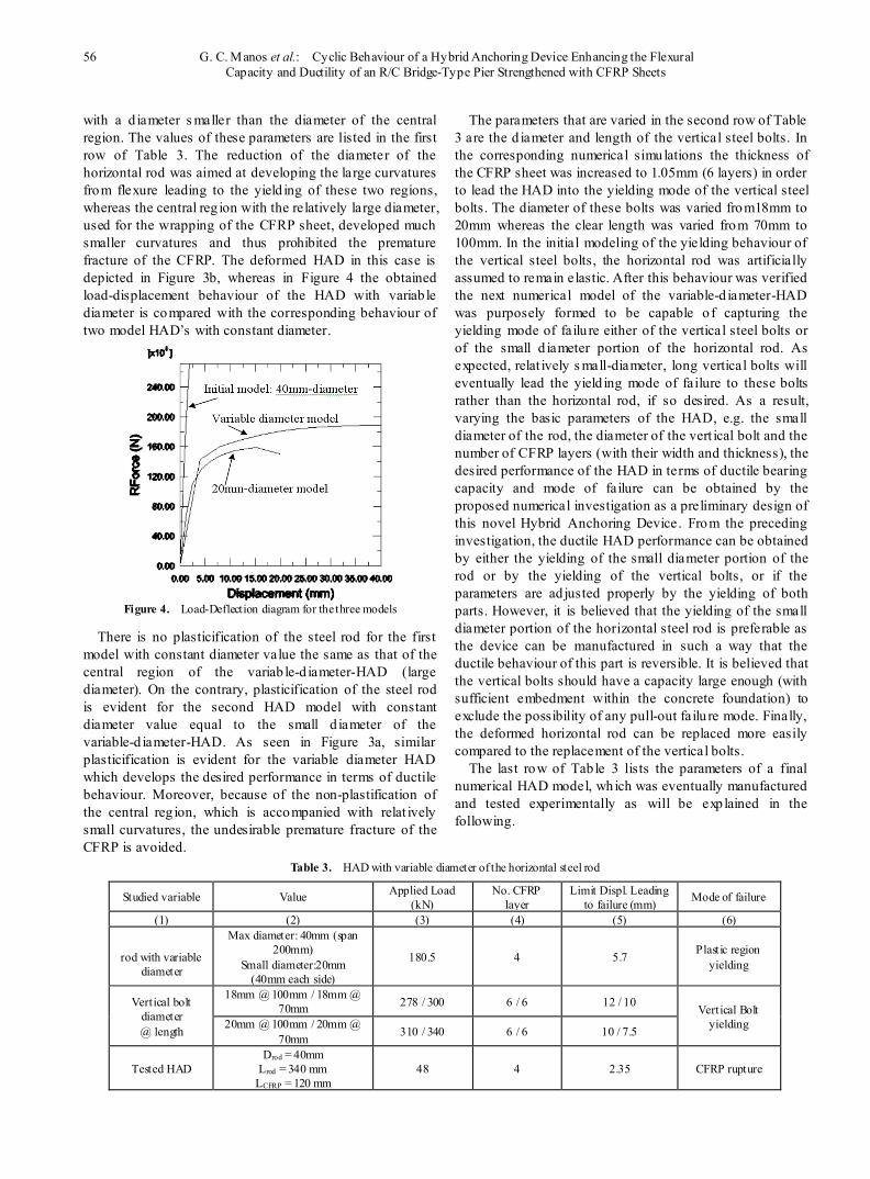
with a d iameter s maller than the diameter of the central region. The values of these parameters are listed in the first row of Table 3. The reduction of the diameter of the horizontal rod was aimed at developing the large curvatures from flexure leading to the yield ing of these two regions, whereas the central reg ion with the relatively large diameter, used for the wrapping of the CFRP sheet, developed much smaller curvatures and thus prohibited the premature fracture of the CFRP. The deformed HAD in this case is depicted in Figure 3b, whereas in Figure 4 the obtained load-displacement behaviour of the HAD with variab le diameter is compared with the corresponding behaviour of two model HAD’s with constant diameter.
Figure 4. Load-Deflection diagram for the three models
There is no plasticification of the steel rod for the first model with constant diameter value the same as that of the central region of the variab le-d iameter-HAD (large diameter). On the contrary, plasticification of the steel rod is evident for the second HAD model with constant diameter value equal to the small d iameter of the variable-d iameter-HAD. As seen in Figure 3a, similar plasticification is evident for the variable diameter HAD which develops the desired performance in terms of ductile behaviour. Moreover, because of the non-plastification of the central reg ion, which is accompanied with relat ively small curvatures, the undesirable premature fracture of the CFRP is avoided.
The parameters that are varied in the second row of Table 3 are the d iameter and length of the vertical steel bolts. In the corresponding numerical simulations the thickness of the CFRP sheet was increased to 1.05mm (6 layers) in order to lead the HAD into the yielding mode of the vertical steel bolts. The diameter of these bolts was varied from18mm to 20mm whereas the clear length was varied from 70mm to 100mm. In the initial modeling of the yielding behaviour of the vertical steel bolts, the horizontal rod was artificially assumed to remain elastic. After this behaviour was verified the next numerical model of the variable-d iameter-HAD was purposely formed to be capable o f capturing the yielding mode of failu re either of the vertical steel bolts or of the small d iameter portion of the horizontal rod. As expected, relat ively s mall-diameter, long vertical bolts will eventually lead the yield ing mode of failure to these bolts rather than the horizontal rod, if so desired. As a result, varying the basic parameters of the HAD, e.g. the small diameter of the rod, the diameter of the vert ical bolt and the number of CFRP layers (with their width and thickness), the desired performance of the HAD in terms of ductile bearing capacity and mode of failure can be obtained by the proposed numerical investigation as a preliminary design of this novel Hybrid Anchoring Device. From the preceding investigation, the ductile HAD performance can be obtained by either the yielding of the small diameter portion of the rod or by the yielding of the vertical bolts, or if the parameters are ad justed properly by the yielding of both parts. However, it is believed that the yielding of the small diameter portion of the horizontal steel rod is preferable as the device can be manufactured in such a way that the ductile behaviour of this part is reversible. It is believed that the vertical bolts should have a capacity large enough (with sufficient embedment within the concrete foundation) to exclude the possibility of any pull-out failu re mode. Finally, the deformed horizontal rod can be replaced more easily compared to the replacement of the vertical bolts.
The last row of Tab le 3 lists the parameters of a final numerical HAD model, which was eventually manufactured and tested experimentally as will be exp lained in the following.
Table 3. HAD with variable diameter of the horizontal steel rod
Studied variable Value Applied Load (kN)
No. CFRP layer
Limit Displ. Leading to failure (mm) Mode of failure
(1) (2) (3) (4) (5) (6)
rod with variable
diameter
Max diameter: 40mm (span 200mm)
Small diameter:20mm (40mm each side)
180.5 4 5.7 Plastic region yielding
Vertical bolt diameter @ length
18mm @ 100mm / 18mm @ 70mm 278 / 300 6 / 6 12 / 10 Vertical Bolt
yielding 20mm @ 100mm / 20mm @ 70mm 310 / 340 6 / 6 10 / 7.5
Tested HAD Drod = 40mm
Lrod = 340 mm LCFRP = 120 mm
48 4 2.35 CFRP rupture

Journal of Civil Engineering Research 2013, 3(1): 52-63 57
This final numerical HAD model, depicted in Figure 5, had a horizontal rod with two specific regions called regions of plastic hinges, which were of a d iameter s maller than the diameter of the horizontal rod away from these regions. This numerical model incorporated all the capabilit ies of the previously performed investigation in terms of non-linear behaviour. Thus, the rod had sufficient diameter at both of its edges as to be able to incorporate relatively large diameter vert ical bolts and confine the yielding of the HAD at specific reg ions named “plastic hinges”. This final numerical HAD model, with the two plastic hinge regions, developed, as expected, a more uniform d istribution of the axial tensile stresses for the CFRP without significant stress concentration that may potentially lead to premature tensile fracture of the CFRP unlike the model with constant diameter. Finally, considerable plastic strains developed at the plastic hinges thus providing this HAD model with the desired ductile behaviour for a target axial load bearing capacity (Figure 9).
Figure 5. Load-Deflection diagram for the three models
Figure 6. Experimental Setup of HAD with plastic regions
Figure7a. The horizontal rod of the HAD with plastic regions
Figure 7b. The horizontal rod of the HAD without plastic regions
3. Experimental Investigation of Pilot HAD
Two p ilot HAD specimens were made and were subjected to a loading pattern as close as possible to the one described in the preceding extensive numerical investigation in order to verify the numerically predicted behaviour. The mechanical p roperties of the materials forming the pilot HAD specimens were obtained by specific tensile experiments that resulted in mechanical values the same as the ones used in the numerical simulation. One pilot HAD specimen was made with a horizontal steel rod of constant diameter whereas the other had a variable diameter with the aforementioned plastic hinge reg ions at specific locations, as shown in Figure 5.
Figure 8. Applied force-measured CFRP strains variation for HAD specimens with or without plastic hinges. Experimental values.
Figure 9. Load-deflection numerical and experimental HAD behaviour
Apart from this d ifference all the rest of the geometric and material properties were the same for both pilot HAD specimens. The depicted geometry is the same as the one assumed as being “typical” for the performed parametric numerical investigation; that is, a horizontal rod with a length of 340mm (290mm from the supports), an init ial diameter of 40mm (and a diameter at the plastic hinge regions of 15mm) and a CFRP layer of thickness 0,7mm (formed by 4 CFRP layers) with a length of 120mm. Each
Plastic regions
Load Cell attached on
Actuator
CFRP wrapped around the rod

58 G. C. Manos et al.: Cyclic Behaviour of a Hybrid Anchoring Device Enhancing the Flexural Capacity and Ductility of an R/C Bridge-Type Pier Strengthened with CFRP Sheets
plastic hinge reg ion had a length of 20mm and each vertical steel bolt was of 18mm diameter and 70mm length. These two pilot HAD specimens, including the CFRP layers wrapped around their horizontal steel rod, were placed in a reaction frame which included a dynamic actuator (Figure 6). The two ends of the horizontal steel rod were attached with the use of the aforementioned “vertical” steel bolts to the reaction frame whereas the edges of the CFRP layers that were placed around the horizontal rod were attached to the sides of a concrete prism, employing epoxy resin and a strong type of mechanical anchorage (Figures 5 and 6). This concrete block was then linked with the dynamic actuator and was subjected to prescribed displacements. The applied load was monitored throughout the loading sequence with a load cell attached in line with the HAD specimen together with the imposed displacement; strain measurements were obtained from both the CFRP sheets, at locations indicated in Figure 7a, and from the horizontal rod, either at the plastic regions (Figure 7b) or at the corresponding location for the pilot HAD specimen without the plastic regions. Both pilot specimens were subjected to a similar loading sequence that aimed to verify the find ings of the numerical investigation. The pilot HAD without the plastic hinges was subjected to a monotonic loading and unloading sequence whereas the pilot HAD with the plastic hinges was subjected to a full cyclic load reversal.
Figure 10a. Numerical vs Experimental load-strain variation for HAD with and without plastic hinges (CFRP strains at edge of the CFRP layers)
Figure 10b. Load-deflection numerical vs experimental HAD behaviour
Since the CFRP sheets are unable to sustain any compressive load, a complementary steel mechanism was
fabricated as part of the variable-diameter HAD and its loading arrangement, in order to apply a full cyclic load sequence (Figure 5). The same mechanis m was part o f the HAD’s that were attached to a trial laboratory application, described in the next section. With this complementary mechanis m, the full cyclic ductile behaviour of the plastic hinge regions could be mobilized for the variable-d iameter-HAD’s; this is known to be a considerable advantage for structures and structural elements subjected to seismic type loading sequences which include many load reversal cycles. Selected experimental measurements are presented in order to substantiate the following: First, to verify that the CFRP sheets wrapped around the pilot HAD having a steel rod with plastic hinges develop a more uniform stress field than the corresponding CFRP layers wrapped around the pilot HAD having a steel rod with a constant diameter, as concluded by the numerical investigation. At the same time to compare the strains that were measured at the CFRP sheets with the values predicted from the corresponding numerical simulation. Next , to compare the measured overall load-displacement response of the pilot HAD specimens with that predicted numerically. Finally, to compare the observed mode of failure for both pilot HAD specimens with the relevant limit states predicted by the numerical simulation.
The term axial strain indicates that the axis of the strains measured by the strain gauges coincide with the axis of the applied load and the axis of the carbon fibers forming the CFRP sheets. The variat ion of the predicted and measured axial strains against the applied load are plotted in Figure 10a. This is done for both pilot HAD specimen with or without plastic reg ions. For g iven amplitude of applied load the strains measured near the edge of the CFRP sheet for the pilot constant-diameter-HAD are considerably larger than the corresponding strains measured at the middle of this CFRP sheet, validating a similar finding of the numerical investigation (Figures 2 and 8). As has been already pointed out, this is an undesirable state of stress which can lead to premature tensile failure of the CFRP sheets. In contrast, the measured strains at the CFRP wrapped around the horizontal rod o f the variable-d iameter-HAD with the plastic hinge regions remain almost constant along the width of this CFRP sheet, a fact that also verifies the numerical investigation findings. On the basis of th is evidence, it can be concluded that the proper location of the “plastic h inge” regions along the span of the horizontal rod of a HAD results in the mit igation of an undesirable non-uniform tensile stress field fo r the wrapped around this rod CFRP sheets. A good agreement between the variation of the applied load with the numerically pred icted and the measured axial strains at the edges of the CFRP sheet wrapped around the rod of the pilot HAD with or without the plastic hinges is depicted in Figure 10a. Figure 9 depicts the measured and numerically predicted applied load – displacement response for the HAD specimen with the plastic hinges. As can be seen in this Figure, the predicted load level that corresponds to the

Journal of Civil Engineering Research 2013, 3(1): 52-63 59
development of large deformat ions (due to the material yielding of the plastic reg ions) agrees well with the corresponding measured value.
Figure 11. Developed strains on CFRP and on plastic region
The measured init ial stiffness is smaller than the numerically pred icted value, a fact that must be attributed to the deformability o f the vert ical steel bolts connecting this pilot HAD specimen to the reaction frame. This observation can also be made when comparing the predicted and measured load-deflection response of the pilot HAD without the plastic hinge regions (Figure 10b). Moreover, as seen in this Figure, the pilot HAD with the plastic hinges develops a ductile non-linear load-deflection cyclic behaviour having an almost elastic – perfect p lastic shape, whereas the CFRP sheet is kept without undesired stress concentration regions. For an applied load of 40.4 kN the measured strain values are compared with the corresponding numerical strains for both the CFRP sheet (left part of Figure 11) and the plastic hinge region of the horizontal rod of the variab le-diameter HAD specimen (right part of Figure 11, ε = 1.13%). Reasonably good agreement can be seen in this comparison. Finally, as discussed in the previous section, the brittle fracture of the CFRP sheet occurred, as expected, for the pilot HAD without the plastic hinge regions. In contrast, the pilot HAD with the plastic hinges exhib ited, as predicted, reasonably good ductile behaviour, due to the yielding of the steel at the plastic regions; this led eventually to the fracture of the left plastic hinge, after a considerable number of load reversals that exceeded the measuring capacity of the strain gauges (Figure 12). On the basis of all these observations it can be concluded that the behaviour of the HAD can be predicted numerically with sufficient accuracy employing the previously prescribed modelling procedure.
Figure 12. Fracture of the left plastic hinge (a) and yielding of the right (b)
4. Application of a HAD to a Model Bridge-Type Pier Specimen
Next, the previously developed HAD, with the plastic hinges, was applied to a model R/C bridge-type pier specimen. This model structure without the HAD’s was constructed and tested in the framework of an extensive research program supported by the European Union[12-15]. Through this application of the HAD, the intention was to increase the flexural capacity of this model R/C bridge-type pier specimen. Only essential details are given here regarding this model structure and the tests incorporating the HAD.
This specimen is shown in Figure 13a with a rectangular cross-section of 200mm x 500mm and height of 1815mm (from its top to the upper surface of its foundation). The longitudinal reinforcement consisted of eight bars of 6mm diameter (8Ø6) that extended with no splices and was anchored to the foundation block; 6mm diameter bars spaced at 100mm (Ø6/100) as closed stirrups was the transverse reinforcement. The selected longitudinal and transverse reinforcement together with the loading arrangement caused the behaviour of this virgin specimen to be dominated by the flexural rather than the shear mode of failure. More details are given in references G. C. Manos et al. 2006 and G. C. Manos et al. 2007[12,15]. The materials that were used in this experimental model are described in Table 4. The pier model was fixed to a concrete foundation block with an area of 1000mm x 1000mm and a depth of 300mm. The foundation was rigidly attached to the strong reaction frame. The specimen was then subjected to a simultaneous constant vertical load and a cyclic horizontal displacement, at a height of 1400mm from the top of the foundation, with increasing amplitude in time, utilizing servo-electronically-controlled dynamic actuators. The frequency of this cyclic displacement, which was varied in amplitude from 2mm to 24mm, was in some tests 0.1Hz whereas in other selected tests it became 1.0Hz. The applied vertical load, which simulates the influence of the compressive force acting on the pier, was kept constant at 95 kN.
Table 4. Properties of the materials
Material Properties Material Properties
Concrete E = 27.5 GPa fc’=25MPa
horizontal rod –
steel-1 (HAD)
E=200GPa fy=360MPa, fult=396MPa
Steel Reinforcement of
Pier
E=200GPa fy=500MPa, fult=550MPa
Vertical bolts – steel-2 (HAD)
E=200GPa fy=550MPa, fult=650MPa
CFRP* E = 500GPa εult= 1.1%
The horizontal imposed cyclic displacement was applied in 13 groups of continuously increasing amplitude. Each group included 3 full cycles of constant amplitude. Figure 13a shows the instrumentation as well the HAD and the wrapped around it CFRP sheet attached at either side of the pier near the foundation block (Figure 13b). The above loading sequence was applied to the virgin bridge pier

60 G. C. Manos et al.: Cyclic Behaviour of a Hybrid Anchoring Device Enhancing the Flexural Capacity and Ductility of an R/C Bridge-Type Pier Strengthened with CFRP Sheets
model, which developed predominantly flexural response and reached a limit state in the form of a horizontal crack near the intersection of the pier and the foundation block. When the horizontal displacement demand was increased, this horizontal crack p rogressed, as expected, in the form of a plastic hinge mobilizing in tension the longitudinal reinforcement and in compression the extreme part of the concrete cross-section at this location at the toe of the pier near the footing. This plastic hinge mechanis m was mobilized through the load-reversals making use of the appropriate part of the concrete cross-section with the corresponding longitudinal reinforcement of the opposite side. As already mentioned, two HAD’S were attached to this pier model as part of a strengthening scheme aimed to improve the flexural capacity of this bridge pier model structure by the use of CFRP sheets applied externally at the two opposite sides of the structure as means of external longitudinal reinforcement; the HAD’s were placed at the right and left sides of the pier very near the intersection with the foundation block. Εach HAD had two layers of CFRP with a thickness of 0.17mm each and a width of 180mm. These CFRP sheets were next bonded at the two opposite sides of the pier, being attached to the concrete part of the pier with mechanical anchors, having being previously wrapped around the horizontal steel rod of each HAD (Figure 13b and Figure 15).
Figure 13. Model pier with instrumentation (a) and HAD attachment (b)
Table 5 summarizes the initial test results with the virgin pier specimen without any HAD’S (virgin-p ier, Figure 14) with the test results from the loading sequence with the specimen including the two HAD’s (Figure 14). The names
2-Pier, 4-Pier, 8-Pier, 16-Pier, 24-Pier, refer to the measured response of the model R/C bridge-type pier specimen with the two HAD’s when the amplitude of the imposed horizontal cyclic d isplacement attained the values of ±2mm, ±4mm, ±8mm, ±16mm, ±24mm, respectively. For low-amplitude horizontal displacement demands (±2mm, ±4mm) the model with the HAD’s developed no visible damage. As the horizontal displacement demand increased (±8m, 8-Pier), the plastic hinge at the joint between the pier and the foundation block became visible. At this horizontal d isplacement level the corresponding horizontal load was considerably larger (58 kN) than the maximum load the model p ier without HAD’s could sustain (37 kN). The development of the plastic hinge at the joint between the model p ier and the foundation block is a visib le indication that the HAD’s and the corresponding CFRP layers are mobilized. For the next two cyclic displacement amplitudes (±16mm, ±24mm), where the HAD’s are fully mobilized by undergoing plastic deformat ions, the ultimate value of the horizontal load the model p ier with the HAD’s could withstand was 100% larger (78 kN) than the maximum load the model p ier without HAD’s could sustain (37 kN). The ±24mm cyclic horizontal displacement level was finally accompanied by the CFRP debonding at the sides of the pier without any sign of failure for any part of the HAD’s. This fact indicates that an improvement o f the bonding of the CFRP layers at the sides by using anchor bolts could increase even further the bearing capacity of the pier model in terms of horizontal load reaching the capacity of the HAD’s themselves.
Figure 14 depicts the cyclic behaviour of the v irgin model pier specimen together with the corresponding behaviour of the model p ier with the HAD’s in terms of horizontal load – horizontal d isplacement envelope curves. The comparison of the behaviour of the model pier in Figure 14 prior and after the application of the HAD’s demonstrates quite clearly the fulfilment of the objectives of this particular strengthening scheme: that is the significant increase of the flexural response bearing capacity (of the order of 100%) with a ductile behaviour which does not result in the premature failu re of the CFRP sheets.
Table 5. Properties of the materials
Specimen name
Target max. Displ.
Pier’s Uplift (mm)
External CFRP Layers
Ultimate Load (kN) Mode of failure
Virgin specimen
without HAD Virgin Pier 18 mm 1.52 No 37 Plastic Hinge (foundation
joint)
Specimen with two HAD’s
2-Pier 2 mm 0.29 Yes 24 No failure 4- Pier 4 mm 0.47 Yes 38 No failure 8-Pier 8 mm 0.89 Yes 58 Plastic Hinge
16-Pier 16 mm 1.67 Yes 72 Plastic Hinge
24-Pier 24 mm 2.46 Yes 78 Plastic Hinge / CFRP debonding at sides
Journal of Civil Engineering Research 2013, 3(1): 52-63 61
Figure 14. Effectiveness of the strengthening scheme
The aforementioned increase in the horizontal load bearing capacity was accompanied by a similar increase at the maximum horizontal displacement capability of the tested model with the HAD’s from 18mm to more than 25mm. This fact results in an increase of 2.5 times the absorbed plastic energy, during the cyclic response. Table 5 lists the measured maximum value of the uplift response between the toe of the model p ier and the foundation block, which for 24-Pier is 2.46mm. Th is value is well compared with the maximum cyclic response value measured during testing of the individual HAD (Figure 9).
4.1. Numerical Simulation of the Cyclic Res ponse of the Pier
The pier model experimental results used to validate the numerical simulat ion using the same 3-D FE software (ABAQUS, section 3). The characteristics of the materials employed in this simulat ion are defined by specific tests (Table 4). A 3-D finite element mesh (figure 15) was employed for the HAD’s, the model pier and its foundation block, which was assumed to be fixed at its bottom surface. This numerical model was subjected initially to a vertical load of 95kN and then to an incremental step-by-step variation of the imposed horizontal d isplacement simulating the experimentally applied horizontal cyclic displacement sequence, as described before.
Figure 15. Numerical vs. Experimental model
First the behaviour of the virg in p ier model without any HAD’s was simulated. The longitudinal steel reinforcement was modeled in this case as a non-linear connector. The mechanical properties of the connector elements are taken to be equivalent to the mechanical properties of the corresponding steel bars as they were measured during the
experimental sequence. Based on these stress-strain properties of the longitudinal steel rein forcing bars a corresponding bilinear load-deflection relationship was obtained for the numerical connector elements. The numerical solution was based on an incremental step-by-step variation of the imposed horizontal displacement. Figure 16 depicts the load-deflect ion cyclic response of the virgin pier model. The measured response is compared with the predicted response obtained through the numerical simulation that was described briefly before. As can be seen from this comparison the agreement that is obtained is reasonably good.
Figure 16. Load –Deflection for virgin Pier (comparison)
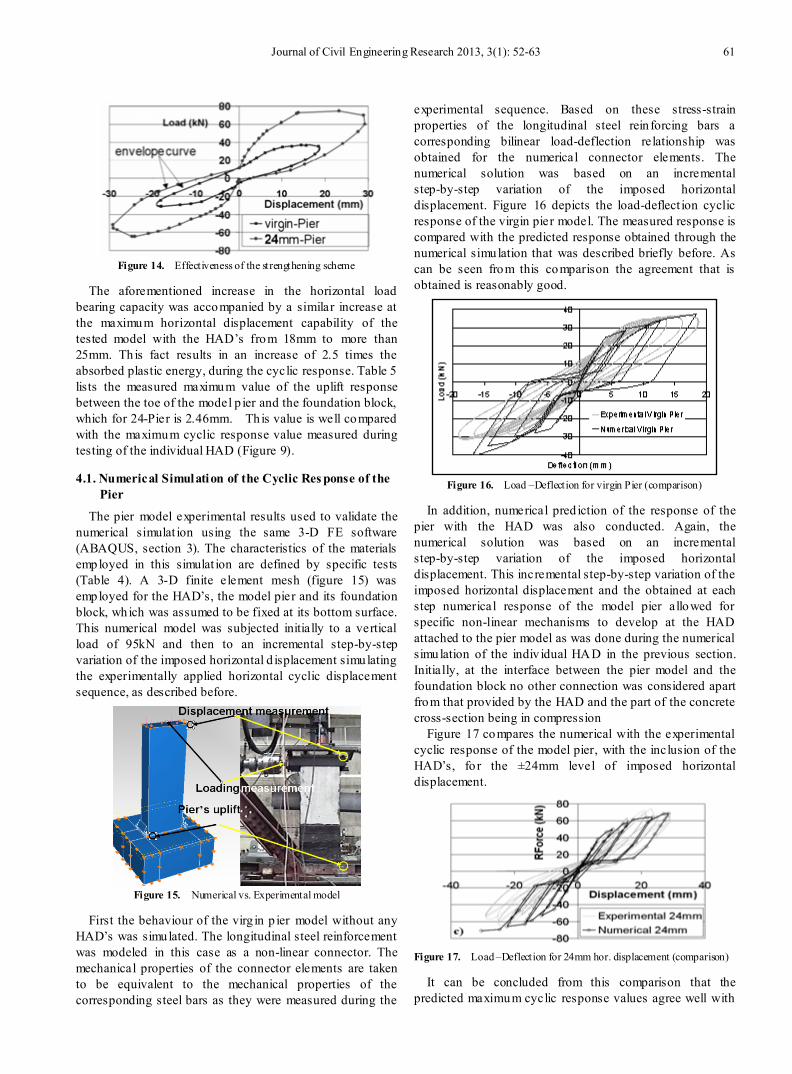
In addition, numerical pred iction of the response of the pier with the HAD was also conducted. Again, the numerical solution was based on an incremental step-by-step variation of the imposed horizontal displacement. This incremental step-by-step variation of the imposed horizontal displacement and the obtained at each step numerical response of the model pier allowed for specific non-linear mechanisms to develop at the HAD attached to the pier model as was done during the numerical simulation of the indiv idual HAD in the previous section. Initially, at the interface between the pier model and the foundation block no other connection was considered apart from that provided by the HAD and the part of the concrete cross-section being in compression
Figure 17 compares the numerical with the experimental cyclic response of the model pier, with the inclusion of the HAD’s, fo r the ±24mm level of imposed horizontal displacement.
Figure 17. Load –Deflection for 24mm hor. displacement (comparison)
It can be concluded from this comparison that the predicted maximum cyclic response values agree well with

62 G. C. Manos et al.: Cyclic Behaviour of a Hybrid Anchoring Device Enhancing the Flexural Capacity and Ductility of an R/C Bridge-Type Pier Strengthened with CFRP Sheets
the experimental results. The numerical model is successful in predict ing the significant increase of the flexural response bearing capacity (of the order of 100%) which was observed during the experiments. Table 6 lists the values of the ultimate load and deflection both as measured during the experiments and as obtained from the numerical simulation of the cyclic response. A comparison between the numerical and the experimental response can be made based on these values, in terms of maximum values, for the most significant response parameters (horizontal displacement, horizontal load, vertical uplift and plastic hinge rotation). This comparison can also be made in terms of cyclic response curves (figure 17), whereby a discrepancy can be observed mainly in terms of stiffness as well as in the energy absorption capability. Therefore, it is concluded that for the studied here strengthening scheme based on the proposed Hybrid Anchoring Devices the influence of the HAD’s could be, in general, accurately predicted but further investigation is needed in a more refined way both numerically and experimentally.
Table 6. Numerical vs. Experimental results for Bridge-Pier with HAD
Numerical Model Experimental Model
Target Displ. 8mm 16mm 24mm 8mm 16mm 24mm
Horiz. Load (kN)
59 68 71 58 75 78
Horiz. Displ (mm)
8 16 24 8 16 24
Vert. Uplift (mm)
0.87 1.51 2.24 0.89 1.67 2.46
Bending Moment (kNm)
82.6 95.2 99.4 81.2 105 109.2
Rot. (10-4 rad) 17 29 44 17 32 48
5. Conclusions 1. A hybrid anchoring device (HAD) was developed and
investigated, in such a way as to be capable of anchoring CFRP sheets to the foundation in order to upgrade the flexural capacity of vertical R/C structural elements.
2. A 3-D non-linear numerical simulat ion was employed for this HAD in order to successfully predict certain limit -state mechanisms that were expected to develop, such as the fracture of the CFRP sheets or the yielding o f the HAD’s steel parts. The parameters that can dictate the development of the desired limit-state were also examined.
3. As a result, such an anchoring device (HAD) with plastic hinge regions was constructed and studied both experimentally and numerically. This HAD exh ibited sufficient ductile behaviour which was accompanied by an axial stress distribution on CFRP sheets that did not exhib it regions of stress concentration, thus avoiding the CFRP
sheets premature longitudinal failure. Moreover, the capability of the adopted numerical modelling to capture the most important features in the behaviour of this HAD was also validated.
4. The applicat ion of such anchoring devices was investigated on a R/C bridge-type pier specimen. The obtained results demonstrated an increase in the specimen’s flexural capacity by 100% as well as a similar increase in its capability of absorbing energy. Moreover, the applied CFRP strengthening scheme combined with the HAD anchoring devices was characterized by a rather ductile behaviour.
5. There was a reasonably good agreement between the measured cyclic response of the pier-type R/C specimen strengthened by CFRP layers, which were anchored by the proposed HADs, and the corresponding numerical predictions. This fact demonstrates the promising potential in employing such numerical tools in the design of strengthening CFRP schemes including the proposed here HAD anchoring system. Certain discrepancies that were observed between the numerically predicted and the observed cyclic response of the pier need further investigation.
6. Further research is under way to develop advanced FE models that account for non-linear concrete behaviour under cyclic loading conditions, FRP delamination and kinemat ic hardening of materials, which will be validated against the herein presented experimental results. Subsequently, parametric studies will be conducted to further optimize the proposed HAD and validate its response under more complicated loading conditions.
ACKNOWLEDGEMENTS The construction and laboratory investigation of the
model p ier has been partially supported by the European Union, Project EVG1-CT-2001-00040 and is here gratefully acknowledged.
REFERENCES [1] C. E. Bakis, L. C. Bank, V. L. Brown, E. Cosenza, J. F.
Davalos, J. J. Lesko, A. Machida, S. H. Rizkalla, T. C. Triantafillou. (2002) Fiber-Reinforced Polymer Composites for Construction - State of the Art Review, Journal of Composites of Construction, ASCE, May 2002.
[2] ACI Committee 440. (2001). ‘‘Guide for the design and construction of concrete reinforced with FRP bars.’’ ACI 440.1 R-01, American Concrete Institute, Farmington Hills,
[3] Mich. Fardis, M. N., and Khalili, H. (1981). ‘‘Concrete encased in fiberglass reinforced plastic.’’ ACI J., 78~6, 440–446.
[4] P. N. Balaguru, S. Kurtz (1998) “Use of inorganic polymer-fiber composites for repair and rehabilitation of

Journal of Civil Engineering Research 2013, 3(1): 52-63 63
infrastructures” Proceedings of the International Seminar on Repair and Rehabilitation of Reinforced Concrete Structures: The State of the Art, 1998, p 155-168
[5] T. E. Maaddawy, K. Soudki. (2007) “Flexural strengthening of R/C slabs with mechanically-anchored unbonded FRP system” FRPRCS-8 World Conference, University of Patras.
[6] A. J. Lamanna, L. C. Bank, D. W. Scott (2004). “Flexural strengthening of R/C beams by mechanically Attaching FRP strips.” Journal of Composites of Construction, ASCE, May/June 2004, 203-210.
[7] J. H. Lee, M. M. Lopez, C. E. Bakis (2007) “Flexural Behaviour of reinforced concrete beams strengthened with mechanically fastened FRP strip.” FRPRCS-8, World Conference, University of Patras.
[8] M. Ekenel, A. Rizzo, J. J. Myers, A. Nanni (2006). “Flexural Fatigue Behaviour of Reinforced Concrete Beams Strengthened with FRP Fabric and Precured Laminate Systems.” Journal of Composites of Construction, ASCE, September/October 2006, 433-442
[9] Nagaraj Eshwar, Antonio Nanni, and Timothy James Ibell (2008). “Performance of Two Anchor Systems of Externally Bonded Fiber-Reinforced Polymer Laminates” ACI Materials Journal, V. 105, No. 1, January-February 2008.
[10] J. D. Hall, P. M. Schuman, H. R. Hamilton III (2002). “Ductile Anchorage for Connecting FRP Strengthening of Under-Reinforced Masonry Buildings.” Journal of Composites of Construction, ASCE, February 2002, 3-10
[11] F. Colomb, E. Ferrier, P. Hamelin (2007). “Anchorage system for external CFRP strengthening seismic reinforcement.” FRPRCS-8, World Conference, University of Patras.
[12] G. C. Manos, V. Kourtidis, V.J. Soulis, A. Sextos, P. Renault (2006). “Study of the dynamic response of a bridge pier model structure at the Volvi European test site”, Proc. 8th U.S. National Conference on Earthquake Engineering, (8NCEE), San Fransisco, California.
[13] G.C. Manos, V. Kourtidis, A. Sextos, P. Renault, S. Chiras (2006). “Dynamic Response of a Bridge Pier Model at the Volvi-Greece European Test Site Including the Soil Flexibility”, 13th European Conference on Earthquake
Engineering, Geneva, Switserland.
[14] G.C. Manos, V. Kourtidis, A. Sextos, P. Renault, S. Chiras (2007) “Study of the Dynamic Soil-Structure Interaction of a Bridge Pier Model based on Structure and Soil Measurements”; 9th Canadian Conference on Earthquake Engineering, Vancouver, Canada.
[15] G.C. Manos, K. Katakalos, V. Kourtides, Ch. Mitsarakais (2007). “Upgrading the Flexural Capacity of a Vertical R/C Member Using Carbon Reinforcing Plastics Applied Externally and Anchored at the Foundation”, FRPRCS-8 World Conference, University of Patras.
[16] G.C.Manos, Konstantinos Katakalos, C.G. Papakonstantinou, “Shear behaviour of rectangular beams strengthened with either carbon or steel fiber reinforced polymers”, Applied Mechanics and Materials (Trans Tech Publications) Vol. 82 (2011) pp 571-576
[17] Konstantinos Katakalos and Christos G. Papakonstantinou, “Fatigue of reinforced concrete beams strengthened with steel reinforced inorganic polymers”, Journ. of Comp. Constr. (ASCE), 13-2, 103-112, 2009
[18] G.C.Manos, Konstantinos Katakalos, V. Kourtides, “The influence of concrete surface preparation when fiber reinforced polymers with different anchoring devices are being applied for strengthening R/C structural members”, Applied Mechanics and Materials (Trans Tech Publications) Vol. 82 (2011) pp 600-605
[19] Christos G. Papakonstantinou and Konstantinos Katakalos. "Mechanical behaviour of high temperature hybrid carbon fiber/titanium laminates", Journ. Eng. Mat. Technol. (ASME ), 131-2, 2009
[20] Christos G. Papakonstantinou and Konstantinos Katakalos. "Flexural Behaviour of Reinforced Concrete Beams strengthened with a hybrid retrofit system", Structural Engineering and Mechanics, Techno Press, 31-5, 2009
[21] G.C.Manos, Konstantinos Katakalos, V. Kourtides. “Construction Structure With Strengthening Device and Method” European Patent Office, 2011, Patent Number “WO2011073696”Kevin R. Fall, W. Richard Stevens, TCP/IP Illustrated, Volume 1: The Protocols, 2nd ed., Addison-Wesley, USA, 2011.