cyber a/t - mitek.ca€¦ · preparing the electrical system ... tools, and foreign objects ......
TRANSCRIPT

Cyber A/TComponent Cutting Saw
Installation Manual
Manual Set 001055 Revision D
Book 3 of 3
Copyright © 2002-2007 MiTek®. All rights reserved.Patented. See Legal Notice for list of patents.
®
Cyber A/TComponent Cutting Saw
Installation Manual
MiTekMachinery Division301 Fountain Lakes Industrial Dr.St. Charles, MO 63301phone: 800-523-3380fax: 314-328-9218www.mii.com
001055-IN
Entire manual 001055Date created 2002Revision DRevision date 06/21/07Revised by R. Tucker
Approved byG. McNeelege
G. PritchettApplicability 60000-xxxEffectivity Frame 412, 10/04Print date 6/22/07
®
U.S. and other patents pending.
001055 Rev. D Legal Noticeii
PatentsMade and sold under one or more of the following patents:
U.S. 6,539,830U.S. 6,702,096Other Patents Pending
Return Goods PolicyReturn goods cannot be accepted without prior authorization and are subject to a restocking charge. The Seller certifies the articles specified herein were produced in compliance with all provisions of the Fair Labor Standards Act of 1938, as amended, including Section 12.—Rev. 6/98
Reporting Errors and Recommending ImprovementsTo report errors or recommend improvements to this manual, please complete the Document Evaluation Form in the appendices. Mail or fax the form to:
MiTek, Machinery Division301 Fountain Lakes Industrial DriveSt. Charles, MO 63301Attn: Engineering ManagerFax: 636-328-9218
Your support in helping MiTek provide unsurpassed machinery and support is appreciated.
Legal Notice
001055 Rev. D Notice of Changeiii
Use this page to record Service Bulletins and Notices that you receive to keep your manual updated.
Equipment ManualCyber® A/T Saw
Service Bulletin or Notice # Dated Title
Notice of Change
001055 Rev. D Table of Contentsiv
Legal Notice . . . . . . . . . . . . . . . . . . . . . . . . . . . . . . . . . . . . . . . . . . . . . . .iiNotice of Change . . . . . . . . . . . . . . . . . . . . . . . . . . . . . . . . . . . . . . . . . . iii
Safety (English) Safety Indicators . . . . . . . . . . . . . . . . . . . . . . . . . . . . . . . . . .SAFETY-2Safety Rules . . . . . . . . . . . . . . . . . . . . . . . . . . . . . . . . . . . . . .SAFETY-3Lockout/Tagout . . . . . . . . . . . . . . . . . . . . . . . . . . . . . . . . . . .SAFETY-5
Lockout/Tagout Guidelines . . . . . . . . . . . . . . . . . . . . . . . . SAFETY-5Electrical Lockout/Tagout Procedures . . . . . . . . . . . . . . . . SAFETY-6Pneumatic System Lockout/Tagout Procedure . . . . . . . . . SAFETY-9
Troubleshooting With an Energized Machine . . . . . . . . . . .SAFETY-9Restricted Zone . . . . . . . . . . . . . . . . . . . . . . . . . . . . . . . . . .SAFETY-10Safety Test . . . . . . . . . . . . . . . . . . . . . . . . . . . . . . . . . . . . . .SAFETY-12
Testing Emergency Stops (E-Stops) . . . . . . . . . . . . . . . . SAFETY-12Checking Saw Blades . . . . . . . . . . . . . . . . . . . . . . . . . . . SAFETY-13Inspecting the Saw . . . . . . . . . . . . . . . . . . . . . . . . . . . . . SAFETY-14
Seguridad (Español) Indicadores de seguridad . . . . . . . . . . . . . . . . . . . . . . . . . .SAFETY-16Reglas de seguridad . . . . . . . . . . . . . . . . . . . . . . . . . . . . . .SAFETY-17Bloqueo/Etiquetado . . . . . . . . . . . . . . . . . . . . . . . . . . . . . . .SAFETY-20
Pautas de bloqueo/etiquetado . . . . . . . . . . . . . . . . . . . . . SAFETY-20Procedimientos de bloqueo/etiquetado eléctricos . . . . . . SAFETY-21Procedimiento de bloqueo/etiquetado del sistema neumático SAFE-TY-24
Solución de problemas con una máquina energizada . . .SAFETY-25Zonas restringida . . . . . . . . . . . . . . . . . . . . . . . . . . . . . . . . .SAFETY-26Prueba de seguridad . . . . . . . . . . . . . . . . . . . . . . . . . . . . . .SAFETY-28
Prueba de frenos de emergencia . . . . . . . . . . . . . . . . . . SAFETY-28Verificación de las hojas de la sierra . . . . . . . . . . . . . . . . SAFETY-29Inspección de la sierra . . . . . . . . . . . . . . . . . . . . . . . . . . . SAFETY-30
Introduction Chapter 1Introduction to the Equipment Manual . . . . . . . . . . . . . . . . . INTRO-31
Purpose and Scope of This Equipment Manual . . . . . . . . INTRO-31Graphics Used to Help Navigate . . . . . . . . . . . . . . . . . . . . INTRO-32Using This Manual . . . . . . . . . . . . . . . . . . . . . . . . . . . . . . . INTRO-33Screen Shots . . . . . . . . . . . . . . . . . . . . . . . . . . . . . . . . . . . INTRO-34
Contacting MiTek . . . . . . . . . . . . . . . . . . . . . . . . . . . . . . . . . . INTRO-34
Prior to Installation Chapter 2MiTek’s Responsibilities . . . . . . . . . . . . . . . . . . . . . . . . . . . . . . . . IN-35
Prior to Installation . . . . . . . . . . . . . . . . . . . . . . . . . . . . . . . . . . . IN-35During Installation . . . . . . . . . . . . . . . . . . . . . . . . . . . . . . . . . . . IN-35
Pre-Installation Overview . . . . . . . . . . . . . . . . . . . . . . . . . . . . . . . IN-36
Preliminary Pages
Table of Contents
001055 Rev. D Table of Contentsv
Space Requirements . . . . . . . . . . . . . . . . . . . . . . . . . . . . . . . . . . . IN-37Space for the Equipment . . . . . . . . . . . . . . . . . . . . . . . . . . . . . . IN-37Space for Operation and Maintenance . . . . . . . . . . . . . . . . . . . IN-37
Location Requirements . . . . . . . . . . . . . . . . . . . . . . . . . . . . . . . . . IN-39Floor Structure . . . . . . . . . . . . . . . . . . . . . . . . . . . . . . . . . . . . . . IN-39Environment . . . . . . . . . . . . . . . . . . . . . . . . . . . . . . . . . . . . . . . . IN-39
Electrical Requirements . . . . . . . . . . . . . . . . . . . . . . . . . . . . . . . . IN-39For the Saw . . . . . . . . . . . . . . . . . . . . . . . . . . . . . . . . . . . . . . . . IN-39For the PC Enclosure . . . . . . . . . . . . . . . . . . . . . . . . . . . . . . . . IN-40
Compressed Air Requirements . . . . . . . . . . . . . . . . . . . . . . . . . . . IN-41Customer-Supplied Parts Required . . . . . . . . . . . . . . . . . . . . . . . IN-42Shipping Information . . . . . . . . . . . . . . . . . . . . . . . . . . . . . . . . . . . IN-42Training Provided . . . . . . . . . . . . . . . . . . . . . . . . . . . . . . . . . . . . . . IN-42
Installation Chapter 3Responsibilities During Installation . . . . . . . . . . . . . . . . . . . . . . . IN-43Delivery . . . . . . . . . . . . . . . . . . . . . . . . . . . . . . . . . . . . . . . . . . . . . . IN-44
Responsibilities During Delivery . . . . . . . . . . . . . . . . . . . . . . . . IN-44Checking for Damage . . . . . . . . . . . . . . . . . . . . . . . . . . . . . . . . IN-44Lifting and Moving the Saw . . . . . . . . . . . . . . . . . . . . . . . . . . . . IN-45
Installation . . . . . . . . . . . . . . . . . . . . . . . . . . . . . . . . . . . . . . . . . . . IN-47Installing the Saw . . . . . . . . . . . . . . . . . . . . . . . . . . . . . . . . . . . . IN-47Installing the Touch Screen Monitor and Computer (PC) . . . . . IN-58Assembling the Waste Conveyor for the Carriage End . . . . . . . IN-62Installing the Incline Conveyor (Optional Equipment) . . . . . . . . IN-64
Electrical . . . . . . . . . . . . . . . . . . . . . . . . . . . . . . . . . . . . . . . . . . . . . IN-65Connecting Power to the Equipment . . . . . . . . . . . . . . . . . . . . . IN-65Inker and/or Catcher Display Options . . . . . . . . . . . . . . . . . . . . IN-68
Computer Warranty . . . . . . . . . . . . . . . . . . . . . . . . . . . . . . . . . . . . IN-68Computer . . . . . . . . . . . . . . . . . . . . . . . . . . . . . . . . . . . . . . . . . . IN-68Touch Screen . . . . . . . . . . . . . . . . . . . . . . . . . . . . . . . . . . . . . . IN-68
Installation Checklist . . . . . . . . . . . . . . . . . . . . . . . . . . . . . . . . . . . IN-69
Startup Chapter 4Preparing the Electrical System . . . . . . . . . . . . . . . . . . . . . . . . . . IN-70Installing Guards and Support Bars . . . . . . . . . . . . . . . . . . . . . . . IN-71Leveling and Anchoring . . . . . . . . . . . . . . . . . . . . . . . . . . . . . . . . IN-73Checking the Details . . . . . . . . . . . . . . . . . . . . . . . . . . . . . . . . . . . IN-74Checking Motor Rotation . . . . . . . . . . . . . . . . . . . . . . . . . . . . . . . . IN-77Safety Tests . . . . . . . . . . . . . . . . . . . . . . . . . . . . . . . . . . . . . . . . . . IN-77
Index IN-78
Table of Contents

001055 Rev. D Safety (English)SAFETY-1
For safety information in Spanish, refer to page SAFETY-15.
Be Careful.Be Safe.
Safety (English)
Cyber® A/T Saw
001055 Rev. D Safety (English)SAFETY-2
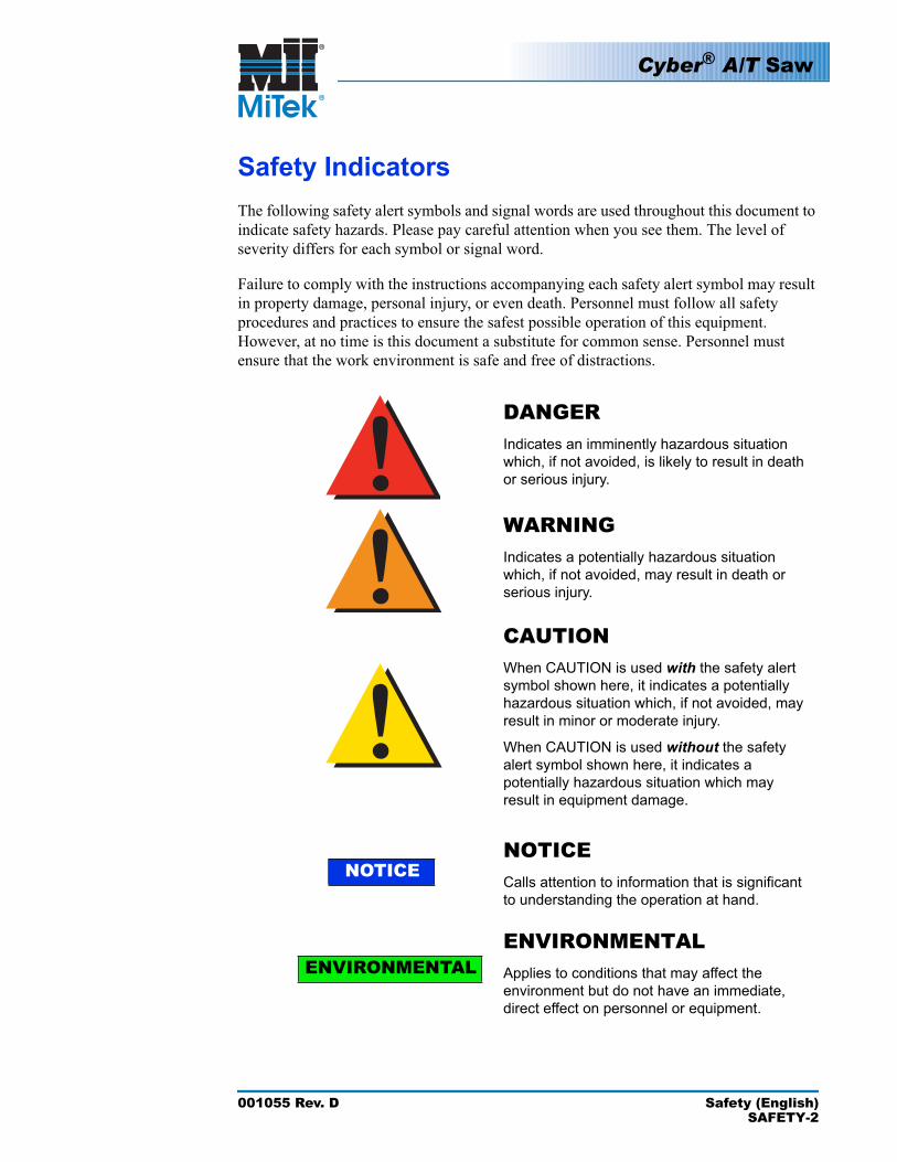
Safety IndicatorsThe following safety alert symbols and signal words are used throughout this document to indicate safety hazards. Please pay careful attention when you see them. The level of severity differs for each symbol or signal word.
Failure to comply with the instructions accompanying each safety alert symbol may result in property damage, personal injury, or even death. Personnel must follow all safety procedures and practices to ensure the safest possible operation of this equipment. However, at no time is this document a substitute for common sense. Personnel must ensure that the work environment is safe and free of distractions.
DANGERIndicates an imminently hazardous situation which, if not avoided, is likely to result in death or serious injury.
WARNINGIndicates a potentially hazardous situation which, if not avoided, may result in death or serious injury.
CAUTIONWhen CAUTION is used with the safety alert symbol shown here, it indicates a potentially hazardous situation which, if not avoided, may result in minor or moderate injury.
When CAUTION is used without the safety alert symbol shown here, it indicates a potentially hazardous situation which may result in equipment damage.
NOTICE
NOTICECalls attention to information that is significant to understanding the operation at hand.
ENVIRONMENTALENVIRONMENTALApplies to conditions that may affect the environment but do not have an immediate, direct effect on personnel or equipment.
NOTICE
!!!
Cyber® A/T Saw
001055 Rev. D Safety (English)SAFETY-3
Safety RulesBecause it is impossible to anticipate every circumstance that might involve a hazard, the safety information provided in this equipment manual and on the machine is not all-inclusive. If this machine is operated or serviced using a procedure not specifically recommended by the manufacturer, the procedure shall be approved by a professional engineer to ensure it will not render the equipment unsafe. Use extreme caution and common sense at all times!
Know Your Equipment• Read this manual completely before using or maintaining the equipment. Do not
operate this machine unless you have a thorough knowledge of the controls, safety devices, emergency stops, and operating procedures outlined in this manual.
• Read and follow all safety notes. Failure to comply with these instructions may result in economic loss, property damage, and/or personal injury including death.
• Refer to the lockout/tagout guidelines on the following pages to safely perform maintenance and troubleshooting of this equipment.
• Observe and obey all safety labels. Replace worn labels immediately.• Use this equipment solely for the purpose described in this manual.• Only qualified personnel should attempt to operate or perform maintenance on this
equipment. “Qualified personnel” is defined as:
...a person or persons who, by possession of a recognized degree or certificate of professional training, or who, by extensive knowledge, training, or experience, has successfully demonstrated the ability to solve problems relating to the subject matter and work—ANSI B30.2-1983
...one who has skills and knowledge related to the construction and operation of the electrical equipment and installations and has received safety training on the hazards involved—NEC 2002 Handbook
Personal Safety• Always wear safety glasses and hearing protection in an industrial environment.• Utilize a filtering facepiece (dust mask) when working near sawdust.• Wear proper clothing and appropriate personal protective equipment (e.g., safety
glasses and hearing protection.) Do not wear loose clothing or jewelry. Confine long hair by tying it back.
• Use caution when lifting heavy parts or material.
Installing the Equipment• Follow installation instructions completely.
Cyber® A/T Saw
001055 Rev. D Safety (English)SAFETY-4
Lockout/Tagout• Before performing maintenance on the pneumatic or hydraulic systems, bleed the
lines to eliminate pressure.• Lockout/tagout all energized systems before performing maintenance on them.
Refer to the Lockout/Tagout Guidelines section on page 5.
Keeping a Safe Environment• Keep children away. All visitors should be kept a safe distance from the work area.
Hazards may not be apparent to individuals unfamiliar with the machine.• Keep work areas well lit.• Keep the work area clean and free of any trip or slip hazards.• Do not use the equipment in damp or wet locations, or expose it to rain or snow.
Operating and Maintaining the Equipment• Ensure that all people, tools, and foreign objects are clear of the restricted zones
before operating this equipment. The restricted zones are shown on page SAFETY-10.
• Perform the safety tests recommended in the Safety Test section on page 12 before operating the equipment at the initial startup, after performing any maintenance, and in accordance with the maintenance schedule.
• In case of machine malfunction, stop the machine immediately using an E-stop and report the malfunction to a supervisor.
• Never leave the machine running unattended. Turn the power off! Do not leave the machine until all parts have come to a complete stop and all electrical power has been shut off.
• Check for worn or damaged parts regularly. Repair or replace them immediately.• Keep the hydraulic, pneumatic, and electrical systems in good working order at all
times. Repair leaks and loose connections immediately. Never exceed the recommended pressure or electrical power.
• Check that all safety devices are in working order before each shift starts. All protective guards and safety devices must be in place before and during use of the machine. Never disconnect or bypass any safety device or electrical interlock.
• Periodically inspect the quality of the finished product.
Electrical Safety• Do not use any liquids in the interior of electrical cabinets.• When using solvents on and around the machine, remove power to the machine to
eliminate the chance of sparking, resulting in explosion or fire. Wear a respirator approved for use with solvents. Wear protective clothing, gloves, and safety glasses.
Cyber® A/T Saw
001055 Rev. D Safety (English)SAFETY-5
Lockout/Tagout
Lockout/Tagout Guidelines
All lockout/tagout guidelines must be met according to OSHA 29 CFR 1910.147. A specific procedure should be included in your company’s energy control program. This manual is not intended to replace your company’s de-energizing or lockout/tagout procedure required by OSHA, but merely to provide general guidance.
Your NameToday’s Date
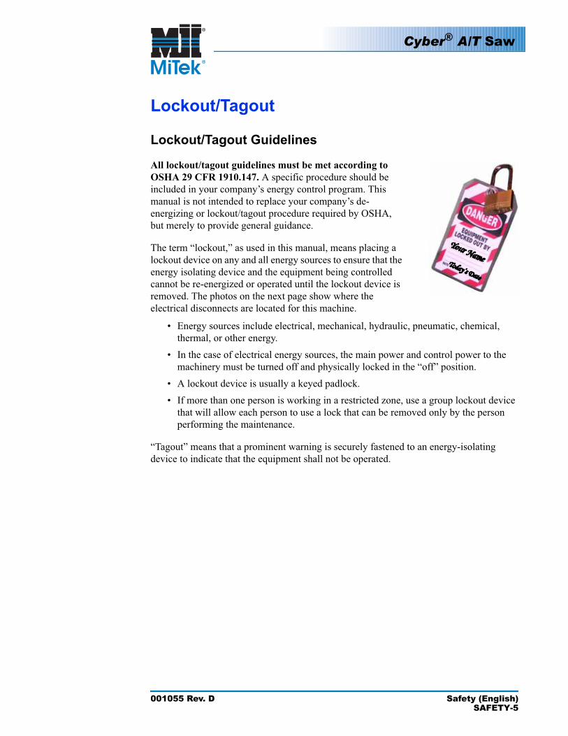
The term “lockout,” as used in this manual, means placing a lockout device on any and all energy sources to ensure that the energy isolating device and the equipment being controlled cannot be re-energized or operated until the lockout device is removed. The photos on the next page show where the electrical disconnects are located for this machine.
• Energy sources include electrical, mechanical, hydraulic, pneumatic, chemical, thermal, or other energy.
• In the case of electrical energy sources, the main power and control power to the machinery must be turned off and physically locked in the “off” position.
• A lockout device is usually a keyed padlock.• If more than one person is working in a restricted zone, use a group lockout device
that will allow each person to use a lock that can be removed only by the person performing the maintenance.
“Tagout” means that a prominent warning is securely fastened to an energy-isolating device to indicate that the equipment shall not be operated.
Cyber® A/T Saw
001055 Rev. D Safety (English)SAFETY-6
Electrical Lockout/Tagout Procedures
When Working on a Machine Outside the Machine’s Main Electrical Enclosure
Before performing maintenance on any machine with electrical power, lockout/tagout the machine properly. When working on a machine outside of the machine’s main electrical enclosure, not including work on the electrical transmission line to the machine, follow your company’s approved lockout/tagout procedures which should include, but are not limited to the steps here.
1. Engage an E-stop on the machine.
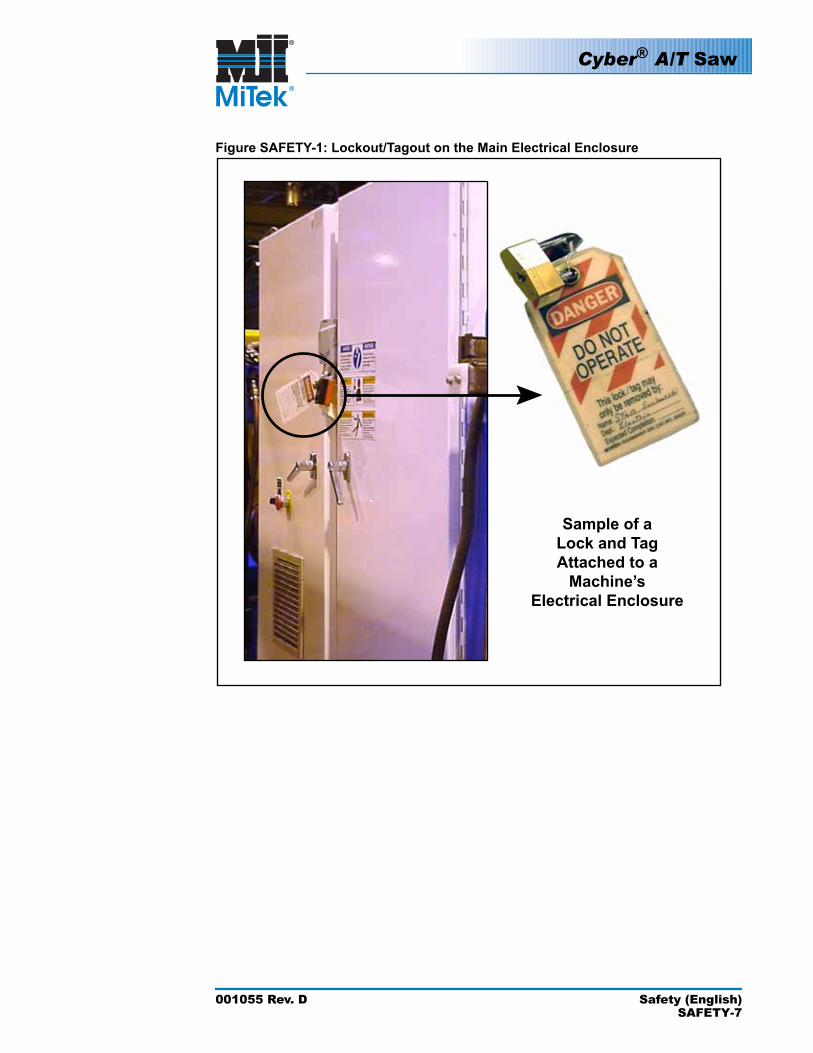
2. Turn the disconnect switch handle on the machine’s main electrical enclosure to the “off” position. See Figure SAFETY-1.
WARNING
ELECTROCUTION HAZARD.
When the disconnect switch is off, there is still live power within the disconnect switch’s enclosure. Always turn off power at the building’s power source to the equipment before opening this electrical enclosure!
3. Attach a lock and tag that meet OSHA requirements for lockout/tagout.
4. Restrain or de-energize all pneumatic components and other parts that could have live or stored power.
If working on the electrical transmission line to the machine, follow the procedure on page 8.
!
Cyber® A/T Saw
001055 Rev. D Safety (English)SAFETY-7
Figure SAFETY-1: Lockout/Tagout on the Main Electrical Enclosure
Cyber® A/T Saw
001055 Rev. D Safety (English)SAFETY-8
When Working on a Machine Inside the Machine’s Main Electrical Enclosure or in the Electrical Transmission Line to the Machine
Before opening the main electrical enclosure, or attempting to repair or replace an electrical transmission line to the machine, lockout/tagout the machine properly. Follow your company’s approved lockout/tagout procedures which should include, but are not limited to the steps here.
1. Engage an E-stop on the machine.
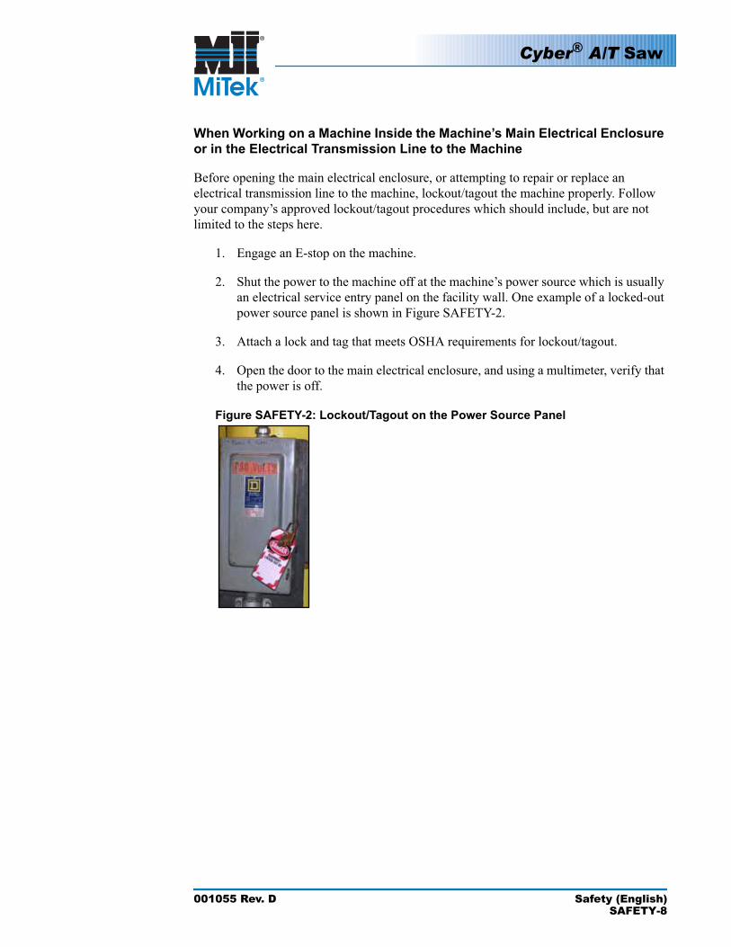
2. Shut the power to the machine off at the machine’s power source which is usually an electrical service entry panel on the facility wall. One example of a locked-out power source panel is shown in Figure SAFETY-2.
3. Attach a lock and tag that meets OSHA requirements for lockout/tagout.
4. Open the door to the main electrical enclosure, and using a multimeter, verify that the power is off.
Figure SAFETY-2: Lockout/Tagout on the Power Source Panel
Cyber® A/T Saw
001055 Rev. D Safety (English)SAFETY-9
Pneumatic System Lockout/Tagout Procedure
When Lockout/Tagout is Not Required
If working on components other than the pneumatic system, but that requires you to be near the vicinity of movable pneumatic components, you must, at a minimum, physically restrain the pneumatic components from moving. If this is not possible, lockout/tagout the entire pneumatic system.
When Lockout/Tagout is Required
Before attempting repair or maintenance on a pneumatic line or component, lockout/ tagout the machine properly. Follow your company’s approved lockout/tagout procedures which should include, but are not limited to the steps here.
1. Follow instructions in the electrical and hydraulic lockout/tagout sections to lockout/tagout or prevent movement of these components.
2. Attach a lock and tag that meet OSHA requirements for lockout/tagout to the air regulator.
3. Bleed all pressure from the reservoir.
4. Bleed all pressure from all pneumatic lines by actuating all pneumatic valves associated with that air source
Troubleshooting With an Energized MachineOnly a qualified electrician, using the personal protective equipment and following the procedures recommended in NFPA 70E should ever attempt service or repair of or near an energized area or component of the machine.
Whenever maintenance is performed while the equipment is electrically energized, there is a potential electric arc flash hazard. Refer to NFPA 70E for the personal protective equipment required when working with electrically energized components. Pneumatic and hydraulic components may move unexpectedly if not de-energized. Physically restrain any components capable of movement when working on or near those components.
Cyber® A/T Saw
001055 Rev. D Safety (English)SAFETY-10
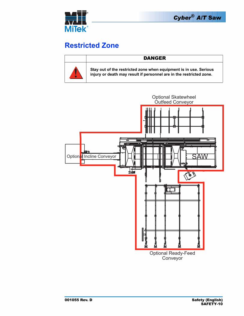
Restricted ZoneDANGER
Stay out of the restricted zone when equipment is in use. Serious injury or death may result if personnel are in the restricted zone.
Optional Skatewheel Outfeed Conveyor
Optional Ready-Feed Conveyor
SAWOptional Incline Conveyor
!
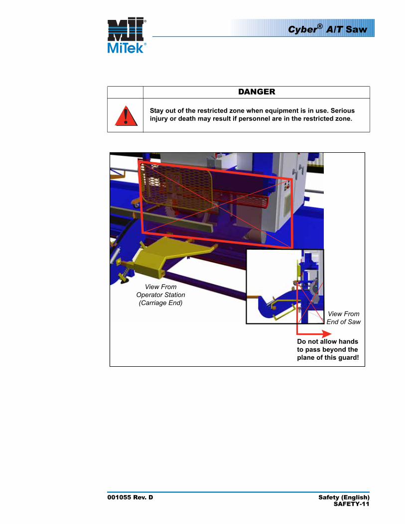
DANGER
Stay out of the restricted zone when equipment is in use. Serious injury or death may result if personnel are in the restricted zone.
Do not allow hands to pass beyond the plane of this guard!
View FromOperator Station(Carriage End)
View FromEnd of Saw
Cyber® A/T Saw
001055 Rev. D Safety (English)SAFETY-11
!
Cyber® A/T Saw
001055 Rev. D Safety (English)SAFETY-12
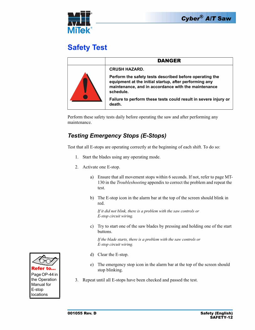
Safety TestDANGER
CRUSH HAZARD.
Perform the safety tests described before operating the equipment at the initial startup, after performing any maintenance, and in accordance with the maintenance schedule.
Failure to perform these tests could result in severe injury or death.
Perform these safety tests daily before operating the saw and after performing any maintenance.
Testing Emergency Stops (E-Stops)
Test that all E-stops are operating correctly at the beginning of each shift. To do so:
1. Start the blades using any operating mode.
2. Activate one E-stop.
a) Ensure that all movement stops within 6 seconds. If not, refer to page MT-130 in the Troubleshooting appendix to correct the problem and repeat the test.
b) The E-stop icon in the alarm bar at the top of the screen should blink in red.
If it did not blink, there is a problem with the saw controls or E-stop circuit wiring.
c) Try to start one of the saw blades by pressing and holding one of the start buttons.
If the blade starts, there is a problem with the saw controls or E-stop circuit wiring.
d) Clear the E-stop.
e) The emergency stop icon in the alarm bar at the top of the screen should stop blinking.Refer to...
Page OP-44 in the Operation Manual for E-stoplocations
3. Repeat until all E-stops have been checked and passed the test.
!
Cyber® A/T Saw
001055 Rev. D Safety (English)SAFETY-13
Checking Saw Blades
DANGERELECTROCUTION, HIGH PRESSURE, CRUSH, AND CUT HAZARDS!
De-energize electrical and hydraulic power using approved lockout/tagout procedures on the power and air supplies before climbing into the saw. Failure to properly lockout/tagout this saw and remove the air supply may allow a blade to move causing severe personal injury or death.
WARNING
CUT HAZARD.
Saw blades are sharp and can cause severe cuts when being handled during installation and removal. Always wear gloves designed for use with sharp objects when handling the blades.
1. Check the condition of all saw blades.
a)
DANGER
Rotate the blade in the cutting direction (toward the operator side). The blade should spin freely without touching the brake and have no indication of wobble. Refer to page MT-127 in the Troubleshootingappendix to correct a wobble.
b) Check for the following items on a daily basis, and replace, repair, or re-tip the blades if any of the following characteristics are found.
•Chipped or missing teeth or dull edges•Pitch build-up•Bending or warping of the blade or cracks in the blade plate (look
carefully around the teeth and screw holes for cracks)
!!
Cyber® A/T Saw
001055 Rev. D Safety (English)SAFETY-14
2. Test the saw blade brakes:
a) To do so, start all saw blades, using any operating mode
b) Press an E-stop or the stop sign on the touch screen.
c) Using a stop watch, measure the time from the moment the stop button is pushed until all saw blades are completely still.
The smaller blades will stop more quickly than the larger blades. All blades must stop within 6 seconds. If they do not, refer to page MT-130 in the Troubleshooting appendix.
stop watch
Inspecting the Saw
DANGER
1. While standing in the saw waste conveyor, and with all power still locked and tagged out, visually check for cables that may interfere with movement of the blades, conveyors, or carriage. Secure cables as necessary.
2. Check that all guards are in place and secure.
a) Check the stationary and movable hold-down guards.
b) Check the lumber stop guard.
c) Check the left and right feed guards.
d) Check the stationary and movable operator guards.
e) Check the rear supports.
DANGERELECTROCUTION, HIGH PRESSURE, CRUSH, AND CUT HAZARDS!
Failure to operate the saw with all safety devices in proper working order and all safety guards in place may result in severe personal injury or death.
3. When all safety tests are completed and passed satisfactorily, restore air and electrical power to the saw.
!
Sea cuidadoso.Protéjase.
001055 Rev. D Seguridad (Español)SAFETY-15
Seguridad (Españñol)
Cyber® A/T Saw
001055 Rev. D Seguridad (Español)SAFETY-16
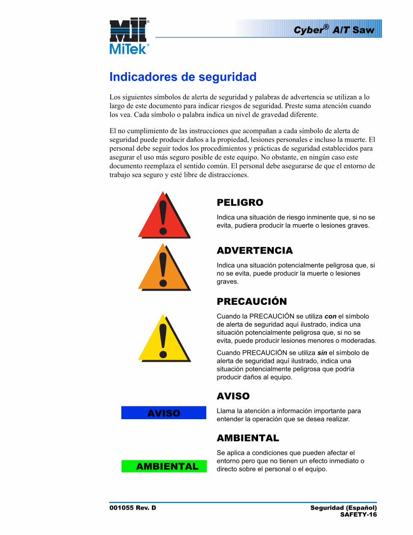
Indicadores de seguridadLos siguientes símbolos de alerta de seguridad y palabras de advertencia se utilizan a lo largo de este documento para indicar riesgos de seguridad. Preste suma atención cuando los vea. Cada símbolo o palabra indica un nivel de gravedad diferente.
El no cumplimiento de las instrucciones que acompañan a cada símbolo de alerta de seguridad puede producir daños a la propiedad, lesiones personales e incluso la muerte. El personal debe seguir todos los procedimientos y prácticas de seguridad establecidos para asegurar el uso más seguro posible de este equipo. No obstante, en ningún caso este documento reemplaza el sentido común. El personal debe asegurarse de que el entorno de trabajo sea seguro y esté libre de distracciones.
PELIGROIndica una situación de riesgo inminente que, si no se evita, pudiera producir la muerte o lesiones graves.
ADVERTENCIAIndica una situación potencialmente peligrosa que, si no se evita, puede producir la muerte o lesiones graves.
PRECAUCIÓNCuando la PRECAUCIÓN se utiliza con el símbolo de alerta de seguridad aquí ilustrado, indica una situación potencialmente peligrosa que, si no se evita, puede producir lesiones menores o moderadas.
Cuando PRECAUCIÓN se utiliza sin el símbolo de alerta de seguridad aquí ilustrado, indica una situación potencialmente peligrosa que podría producir daños al equipo.
NOTICELlama la atención a información importante para entender la operación que se desea realizar.
AMBIENTALSe aplica a condiciones que pueden afectar el entorno pero que no tienen un efecto inmediato o directo sobre el personal o el equipo.
AVISO
!!!
AVISO
AMBIENTAL
Cyber® A/T Saw
001055 Rev. D Seguridad (Español)SAFETY-17
Reglas de seguridadDebido a la imposibilidad de anticipar todas las circunstancias que podrían constituir un riesgo, la información de seguridad suministrada en este manual del equipo y sobre la máquina no es exhaustiva. Si se utiliza o realiza el mantenimiento de esta máquina utilizando un procedimiento no recomendado específicamente por el fabricante, el procedimiento deberá ser aprobado por un ingeniero profesional para asegurarse de que no afecte la seguridad del equipo. ¡Manéjese! siempre con suma precaución y sentido común!
Conozca su equipo• Lea este manual en su totalidad antes de utilizar o mantener el equipo. No utilice
esta máquina a menos que esté perfectamente familiarizado con los controles, los dispositivos de seguridad, los frenos de emergencia y los procedimientos operativos que se describen en este manual.
• Lea y siga todas las notas de seguridad. El no cumplimiento de estas instrucciones podría producir pérdidas económicas, daños a la propiedad y lesiones personales, incluida la muerte.
• Refiérase a las pautas de bloqueo/etiquetado proporcionadas en las siguientes páginas para realizar el mantenimiento y solucionar problemas de este equipo en forma segura.
• Observe y cumpla con todas las etiquetas de seguridad. Cambie las etiquetas gastadas inmediatamente.
• Utilice este equipo únicamente para el propósito que se describe en este manual.• Sólo personal calificado debe intentar utilizar o realizar el mantenimiento de este
equipo. Por "personal calificado" se entiende:
...una persona o personas que, por el hecho de poseer un título o certificado de capacitación profesional reconocido o que, por sus amplios conocimientos o experiencia, han demostrado con éxito estar capacitados para resolver problemas relacionados con el tema y el trabajo en cuestión—ANSI B30.2-1983
...una persona que posee habilidades y conocimientos relacionados con la construcción y uso de equipos e instalaciones eléctricas y que ha recibido capacitación en seguridad sobre los riesgos posibles—NEC 2002 Handbook
Seguridad personal• Use siempre anteojos de seguridad y protección auditiva en un entorno industrial.• Utilice una máscara protectora cuando trabaje cerca de aserrín.• Utilice ropa adecuada y equipo de protección personal apropiado (por ejemplo,
anteojos de seguridad y protección auditiva.) No use ropa suelta ni joyas. Si tiene el cabello largo, áteselo para atrás.
• Proceda con precaución cuando levante piezas o materiales pesados.
Cyber® A/T Saw
001055 Rev. D Seguridad (Español)SAFETY-18
Instalación del equipo• Siga las instrucciones de instalación al pie de la letra.
Procedimientos de Bloqueo/Etiquetado• Antes de realizar el mantenimiento de los sistemas neumáticos o hidráulicos,
purgue las líneas para eliminar la presión.• Bloquee y etiquete todos los sistemas energizados antes de realizar tareas de
mantenimiento en ellos. Refiérase a la sección Pautas de bloqueo/etiquetado en la página 20.
Cómo mantener un entorno seguro• Mantenga alejados a los niños. Todos los visitantes deben mantenerse a una
distancia segura del área de trabajo. Los riesgos pueden no ser evidentes a las personas no familiarizadas con la máquina.
• Mantenga las áreas de trabajo bien iluminadas.• Mantenga el área de trabajo limpia y libre de cualquier riesgo de tropiezo o
resbalamiento.• No utilice el equipo en lugares húmedos o mojados y no lo exponga a la lluvia o a la
nieve.
Uso y mantenimiento del equipo• Asegúrese de que no haya personas, herramientas y objetos extraños en las zonas
restringidas antes de utilizar este equipo. Las zonas restringidas se indican en la página 26.
• Realice las pruebas de seguridad recomendadas en la sección Prueba de seguridad en la página 28 antes de utilizar el equipo por primera vez, después de cualquier tarea de mantenimiento y conforme a la frecuencia de mantenimiento establecida.
• En caso de que la máquina no funcione correctamente, deténgala inmediatamente utilizando un freno de emergencia e informe el problema a un supervisor.
• No deje nunca la máquina encendida si no está junto a ella. ¡Apáguela!. No abandone la máquina hasta que todas las piezas se detengan completamente y hasta que se haya apagado la alimentación eléctrica.
• Verifique periódicamente que no haya piezas gastadas o dañadas. Repárelas o cámbielas inmediatamente.
• Mantenga los sistemas hidráulicos, neumáticos y eléctricos en buen funcionamiento en todo momento. Repare las fugas y las conexiones sueltas inmediatamente. No exceda nunca la presión ni potencia eléctrica recomendadas.
• Verifique que todos los dispositivos de seguridad estén en buen funcionamiento al comienzo de cada turno. Todos los dispositivos protectores y de seguridad deben
Cyber® A/T Saw
001055 Rev. D Seguridad (Español)SAFETY-19
estar en su lugar antes y durante el uso de la máquina. No desconecte ni evite nunca ningún dispositivo de seguridad ni interbloqueo eléctrico.
• Inspeccione periódicamente la calidad del producto terminado.
Seguridad eléctrica• No utilice líquidos en el interior de los gabinetes eléctricos.• Cuando utilice disolventes sobre o alrededor de la máquina, desconecte la
alimentación para eliminar las probabilidades de chispas, que pueden producir una explosión o incendio. Use un respirador aprobado para el uso con disolventes. Use ropa protectora, guantes y anteojos de seguridad.
Cyber® A/T Saw
001055 Rev. D Seguridad (Español)SAFETY-20
Bloqueo/Etiquetado
Pautas de bloqueo/etiquetado
Deben cumplir con todas las pautas de bloqueo/etiquetado conforme a la norma OSHA 29 CFR 1910.147. El programa de control de energía de la compañía debe incluir un procedimiento específico. El objetivo de este manual no es reemplazar el procedimiento de desenergización o bloqueo/etiquetado requerido por la OSHA, sino proporcionar pautas orientativas generales. Your Name
Today’s Date
Su nombreLa fecha de hoy
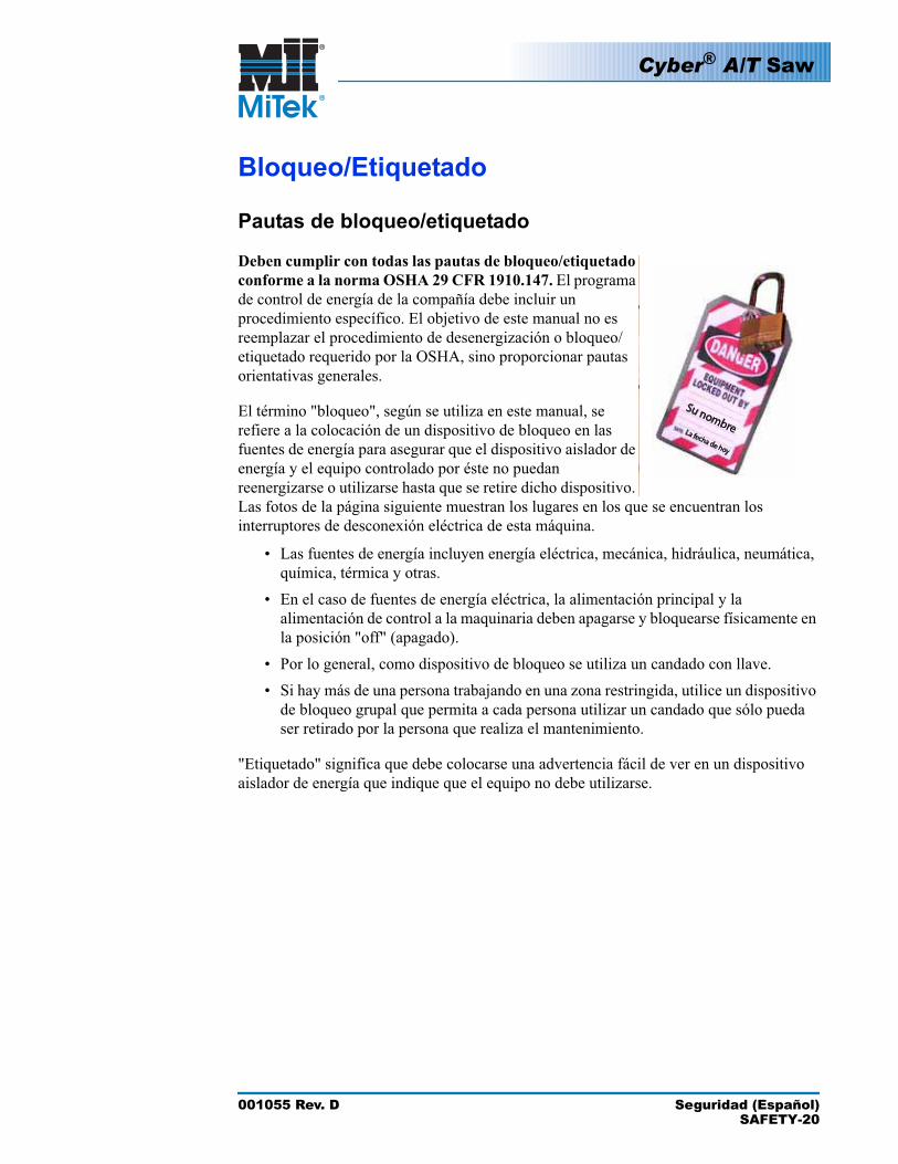
El término "bloqueo", según se utiliza en este manual, se refiere a la colocación de un dispositivo de bloqueo en las fuentes de energía para asegurar que el dispositivo aislador de energía y el equipo controlado por éste no puedan reenergizarse o utilizarse hasta que se retire dicho dispositivo. Las fotos de la página siguiente muestran los lugares en los que se encuentran los interruptores de desconexión eléctrica de esta máquina.
• Las fuentes de energía incluyen energía eléctrica, mecánica, hidráulica, neumática, química, térmica y otras.
• En el caso de fuentes de energía eléctrica, la alimentación principal y la alimentación de control a la maquinaria deben apagarse y bloquearse físicamente en la posición "off" (apagado).
• Por lo general, como dispositivo de bloqueo se utiliza un candado con llave.• Si hay más de una persona trabajando en una zona restringida, utilice un dispositivo
de bloqueo grupal que permita a cada persona utilizar un candado que sólo pueda ser retirado por la persona que realiza el mantenimiento.
"Etiquetado" significa que debe colocarse una advertencia fácil de ver en un dispositivo aislador de energía que indique que el equipo no debe utilizarse.
Cyber® A/T Saw
001055 Rev. D Seguridad (Español)SAFETY-21
Procedimientos de bloqueo/etiquetado eléctricos
Cuando trabaja en una máquina fuera del gabinete eléctrico principal de la máquina
Antes de realizar el mantenimiento de cualquier máquina con alimentación eléctrica, bloquee y etiquete la máquina de forma adecuada. Cuando trabaje en una máquina fuera del gabinete eléctrico principal de la máquina, salvo en el caso de trabajos en la línea de transmisión eléctrica a la máquina, siga los procedimientos de bloqueo/etiquetado aprobados por la compañía, los cuales deberían incluir, entre otros, los pasos aquí indicados.
1. Coloque un freno de emergencia sobre la máquina.
2. Coloque el mango del interruptor con fusibles del gabinete eléctrico principal de la máquina en la posición "apagado/apagada". Vea la figura 2-1.
ADVERTENCIA
RIESGO DE ELECTROCUCIÓN.
Cuando el interruptor con fusibles está apagado, sigue habiendo energía dentro del gabinete del interruptor. ¡Apague siempre la alimentación en la fuente de alimentación del edificio antes de abrir este gabinete eléctrico!
3. Coloque un candado y una etiqueta que cumplan con los requisitos de bloqueo/etiquetado de la OSHA.
4. Trabe o desenergice todos los componente neumáticos y otras piezas que tengan alimentación directa o almacenada.
Si trabaja en la línea de transmisión eléctrica a la máquina, siga el procedimiento de la página 23.
!

Cyber® A/T Saw
001055 Rev. D Seguridad (Español)SAFETY-22
Figure SAFETY-1: Bloqueo/etiquetado en el gabinete eléctrico principall
Ejemplo de un candado y etiqueta fijados al gabinete eléctrico de una
máquina
NO
UTILIZAR
Cyber® A/T Saw
001055 Rev. D Seguridad (Español)SAFETY-23
Cuando trabaje en una máquina dentro del gabinete eléctrico principal de la máquina o en la línea de transmisión eléctrica a la máquina
Antes de abrir el gabinete eléctrico principal o intentar reparar o reemplazar una línea de transmisión eléctrica a la máquina, bloquee y etiqueta la máquina en forma adecuada. Siga los procedimientos de bloqueo/etiquetado aprobados por la compañía, los cuales deberían incluir, entre otros, los pasos aquí indicados.
1. Coloque un freno de emergencia sobre la máquina.
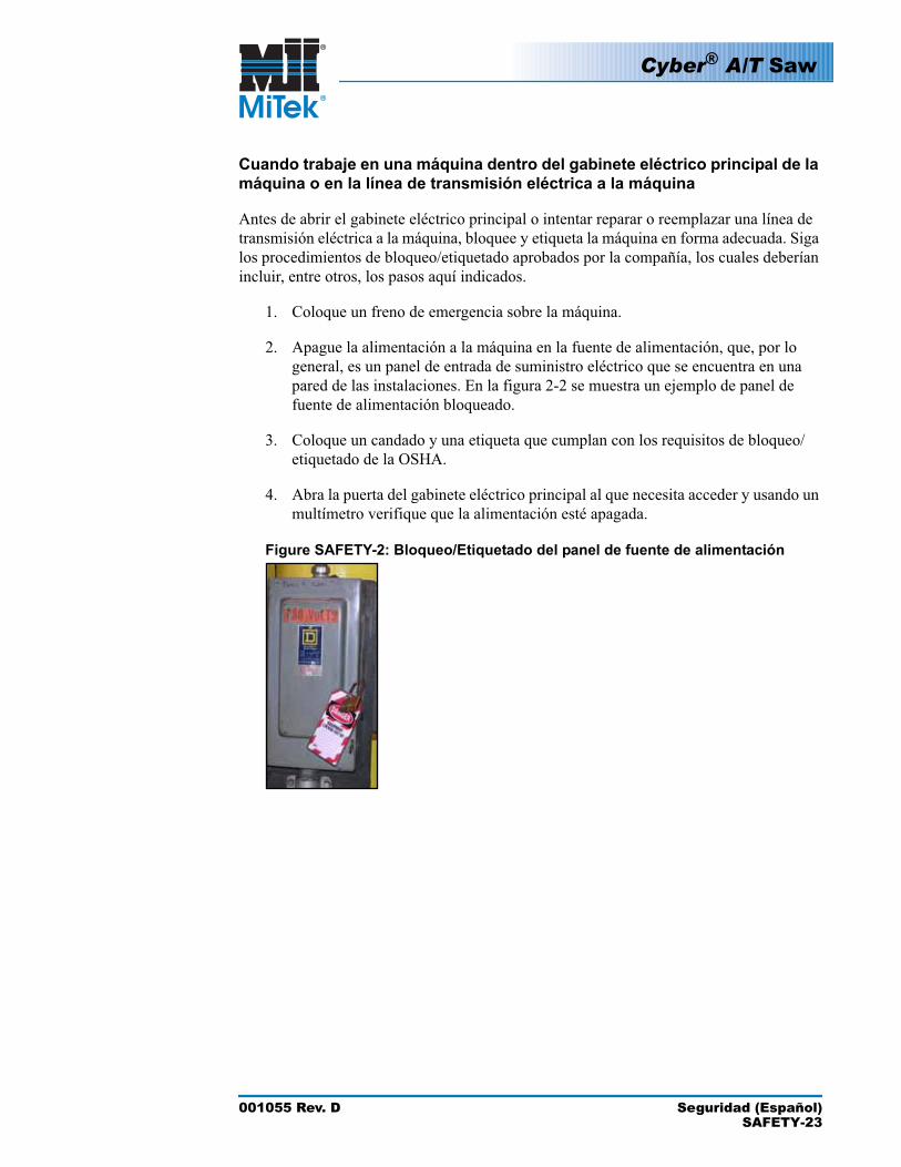
2. Apague la alimentación a la máquina en la fuente de alimentación, que, por lo general, es un panel de entrada de suministro eléctrico que se encuentra en una pared de las instalaciones. En la figura 2-2 se muestra un ejemplo de panel de fuente de alimentación bloqueado.
3. Coloque un candado y una etiqueta que cumplan con los requisitos de bloqueo/etiquetado de la OSHA.
4. Abra la puerta del gabinete eléctrico principal al que necesita acceder y usando un multímetro verifique que la alimentación esté apagada.
Figure SAFETY-2: Bloqueo/Etiquetado del panel de fuente de alimentación
Cyber® A/T Saw
001055 Rev. D Seguridad (Español)SAFETY-24
Procedimiento de bloqueo/etiquetado del sistema neumático
Cuando no se requiere bloqueo/etiquetado
Si trabaja con componentes que no son del sistema neumático pero que requieren su presencia en la proximidad de componentes neumáticos móviles, debe, como mínimo, trabar físicamente estos componentes para que no se muevan. Si no es posible, bloquee/etiquete todo el sistema neumático.
Cuando se requiere bloqueo/etiquetado
Antes de intentar reparar o realizar el mantenimiento de una línea o componente neumático, bloquee/etiquete la máquina en forma apropiada. Siga los procedimientos de bloqueo/etiquetado aprobados por la compañía, los cuales deberían incluir, entre otros, los pasos aquí indicados.
1. Siga las instrucciones de las secciones de bloqueo/etiquetado eléctrico y neumático para bloquear y etiquetar o evitar el movimiento de estos componentes.
2. Coloque un candado y una etiqueta que cumplan con los requisitos de bloqueo/etiquetado de la OSHA en el regulador de aire.
3. Purgue toda la presión del reservorio.
4. Purgue la presión de todas las líneas neumáticas activando las válvulas neumáticas asociadas con dicha fuente de aire.
Cyber® A/T Saw
001055 Rev. D Seguridad (Español)SAFETY-25
Solución de problemas con una máquina energizadaSólo un electricista calificado que utilice el equipo de protección personal y siga los procedimientos recomendados en la norma NFPA 70E debe intentar realizar tareas de reparación o mantenimiento en un área o componente energizados de la máquina o en su proximidad.
Cada vez que se realizan tareas de mantenimiento mientras el equipo está eléctricamente energizado, existe un riesgo potencial de formación de un arco eléctrico. Consulte en la norma NFPA 70E el equipo de protección personal requerido para trabajar con componentes eléctricamente energizados. Los componentes neumáticos e hidráulicos pueden moverse de manera imprevista si no se desenergizan. Trabe físicamente cualquier componente que pueda moverse cuando deba trabajar en ellos o en su proximidad.
Cyber® A/T Saw
001055 Rev. D Seguridad (Español)SAFETY-26
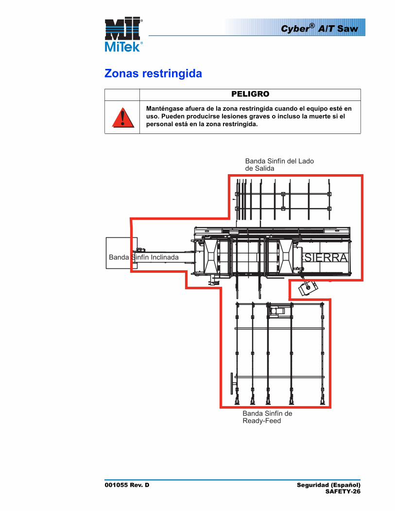
Zonas restringidaPELIGRO
Manténgase afuera de la zona restringida cuando el equipo esté en uso. Pueden producirse lesiones graves o incluso la muerte si el personal está en la zona restringida.
Banda Sinfín del Lado de Salida
Banda Sinfín de Ready-Feed
SIERRABanda Sinfín Inclinada
!
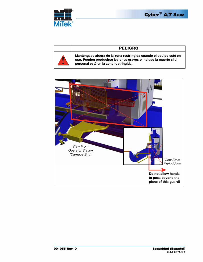
PELIGRO
Manténgase afuera de la zona restringida cuando el equipo esté en uso. Pueden producirse lesiones graves o incluso la muerte si el personal está en la zona restringida.
Do not allow hands to pass beyond the plane of this guard!
View FromOperator Station(Carriage End)
View FromEnd of Saw
Cyber® A/T Saw
001055 Rev. D Seguridad (Español)SAFETY-27
!
Cyber® A/T Saw
001055 Rev. D Seguridad (Español)SAFETY-28
Prueba de seguridadPELIGRO
RIESGO DE APLASTAMIENTO.
Realice las pruebas de seguridad que se describen antes de utilizar el equipo por primera vez, después de cualquier tarea de mantenimiento y conforme con la frecuencia de mantenimiento establecida. Si no se realizan estas pruebas, pueden producirse lesiones graves e incluso la muerte.
Realice estas pruebas de seguridad a diario antes de utilizar la sierra y después de cualquier tarea de mantenimiento.
Prueba de frenos de emergencia
Verifique que todos los frenos de emergencia estén funcionando correctamente al comienzo de cada turno. Para ello, proceda como se indica a continuación:
1. Ponga en marcha las hojas en cualquier modo de funcionamiento.
2. Active un freno de emergencia.
a) Asegúrese de que las hojas se detengan completamente dentro de los 6 segundos. Si esto no ocurre, refiérase a la página MT-136 del apéndice de Solución de problemas para remediar el problema y repita la prueba.
b) El icono de freno de emergencia en la barra de alarma en la parte superior de la pantalla debería parpadear de color rojo.
Si no parpadea, hay un problema con los controles de la sierra o con las conexiones del circuito del freno de emergencia.
c) Intente poner en marcha una de las hojas de la sierra presionando y manteniendo presionado uno de los botones de arranque.
Si la hoja se pone en marcha, hay un problema con los controles de la sierra o con las conexiones del circuito del freno de emergencia.
d) Desconecte el freno de emergencia.
e) El icono de freno de emergencia en la barra de alarma en la parte superior de la pantalla debería dejar de parpadear.
la página OP-23 del Manual de uso las ubicaciones de los frenos de emergencia
Consulte en ...
3. Repita el procedimiento hasta que todos los frenos de emergencia hayan sido verificados y pasen la prueba.
!
Cyber® A/T Saw
001055 Rev. D Seguridad (Español)SAFETY-29
Verificación de las hojas de la sierra
PELIGRO¡RIESGO DE ELECTROCUCIÓN, ALTA PRESIÓN, APLASTAMIENTO Y CORTE!
Desconecte la energía eléctrica e hidráulica utilizando procedimientos de bloqueo/etiquetado aprobados en el suministro de alimentación y aire antes de subirse a la sierra. Si no bloquea/etiqueta la sierra y elimina el suministro de aire, la sierra podría moverse y causar lesiones personales graves e incluso la muerte.
ADVERTENCIA
RIESGO DE CORTE.
Las hojas de la sierra son afiladas y pueden producir cortes graves cuando están siendo manejadas durante la instalación y la eliminación. Use siempre guantes diseñados para trabajar con objetos afilados cuando manipule las hojas.
1. Verifique el estado de todas las hojas de la sierra.
a) Haga girar la hoja en la dirección de corte (hacia el lado del operador). La hoja debería girar libremente sin tocar el freno y sin tambalearse. Si tambalea, refiérase a la página MT-133 del apéndice de Solución de problemas para remediar el problema.
b) Verifique lo siguiente a diario y cambie, repare o afile las hojas si encuentra cualquiera de las características enumeradas a continuación.
•Dientes muescados o faltantes o bordes desafilados•Acumulación de brea•Doblado o pandeado de la hoja o grietas en la placa de la hoja (mire
con atención alrededor de los dientes y los orificios de los tornillos para asegurarse de que no haya grietas)
!
!
Cyber® A/T Saw
001055 Rev. D Seguridad (Español)SAFETY-30
2. Pruebe los frenos de la hoja de la sierra:
a) Para ello, ponga en marcha todas las hojas en cualquier modo de funcionamiento.
b) Presione un freno de emergencia o el signo STOP (ALTO) en la pantalla táctil.
c) Con un cronómetro, mida el tiempo transcurrido desde el momento en que presiona el botón STOP (ALTO) hasta que todas las hojas de la sierra se hayan detenido completamente.
Las hojas más pequeñas se detendrán con más rapidez que las más grandes. Todas las hojas deben detenerse dentro de los 6 segundos. Si esto no ocurre, refiérase a la página MT-136 del apéndice de Solución de problemas.
cronómetro
Inspección de la sierra
DANGER
1. Mientras está de pie en la banda transportadora de desperdicios, y con toda la alimentación aún bloqueada y etiquetada, inspeccione visualmente que no haya cables que interfieran con el movimiento de las hojas, las bandas transportadoras o el carro. Fije los cables cuando sea necesario.
2. Verifique que todos las protectores estén en su lugar y bien fijados.
a) Verifique los protectores sujetadores fijos y móviles.
b) Verifique el protector de tope de la madera.
c) Verifique los protectores de alimentación izquierdo y derecho.
d) Verifique los protectores fijos y móviles del operario.
e) Verifique los soportes traseros
PELIGRO¡RIESGO DE ELECTROCUCIÓN, ALTA PRESIÓN, APLASTAMIENTO Y CORTE!
Si la sierra no se utiliza con todos los dispositivos de seguridad en perfecto estado de funcionamiento y con todos los protectores de seguridad en su lugar, pueden producirse lesiones personales, incluida la muerte.
3. Una vez realizadas todas las pruebas de seguridad y una vez que hayan sido aprobadas en forma satisfactoria, restaure la alimentación de aire y eléctrica a la sierra.
!

001055 Rev. D IntroductionINTRO-31
Introduction to the Equipment Manual
DANGER
Read this manual completely before using this equipment!
Do not operate this machine until you have a thorough understanding of all controls, safety devices, emergency stops, and operating procedures outlined in this manual.
All warnings must be read and observed. Failure to do so may result in economic loss, property damage, and/or personal injury.
This manual must always be available to personnel operating and maintaining this equipment.
Purpose and Scope of This Equipment Manual
This equipment manual (set of three books) provides the information necessary to operate and maintain this equipment. In order for this equipment manual to be useful, it must be easily accessible to the operators and maintenance personnel. Review the table of contents to understand the structure of the chapters. The appendices, indices, and glossary are also valuable tools for getting the most out of your equipment. They are located at the back of the Maintenance Manual.
This equipment manual addresses the current versions of the MiTek® Cyber® A/T saw although some major features and components on previous versions of the saw are addressed to clarify certain items.
!
Introduction
This chapter explains how to navigate through the entire equipment manual and how to contact MiTek.
Chapter 1
Cyber® A/T Saw
001055 Rev. D IntroductionINTRO-32
Graphics Used to Help Navigate
The graphics in Table 1-1 are used throughout the manual to quickly communicate a specific type of information.
Table 1-1: Navigational Tools Used Throughout the Manual
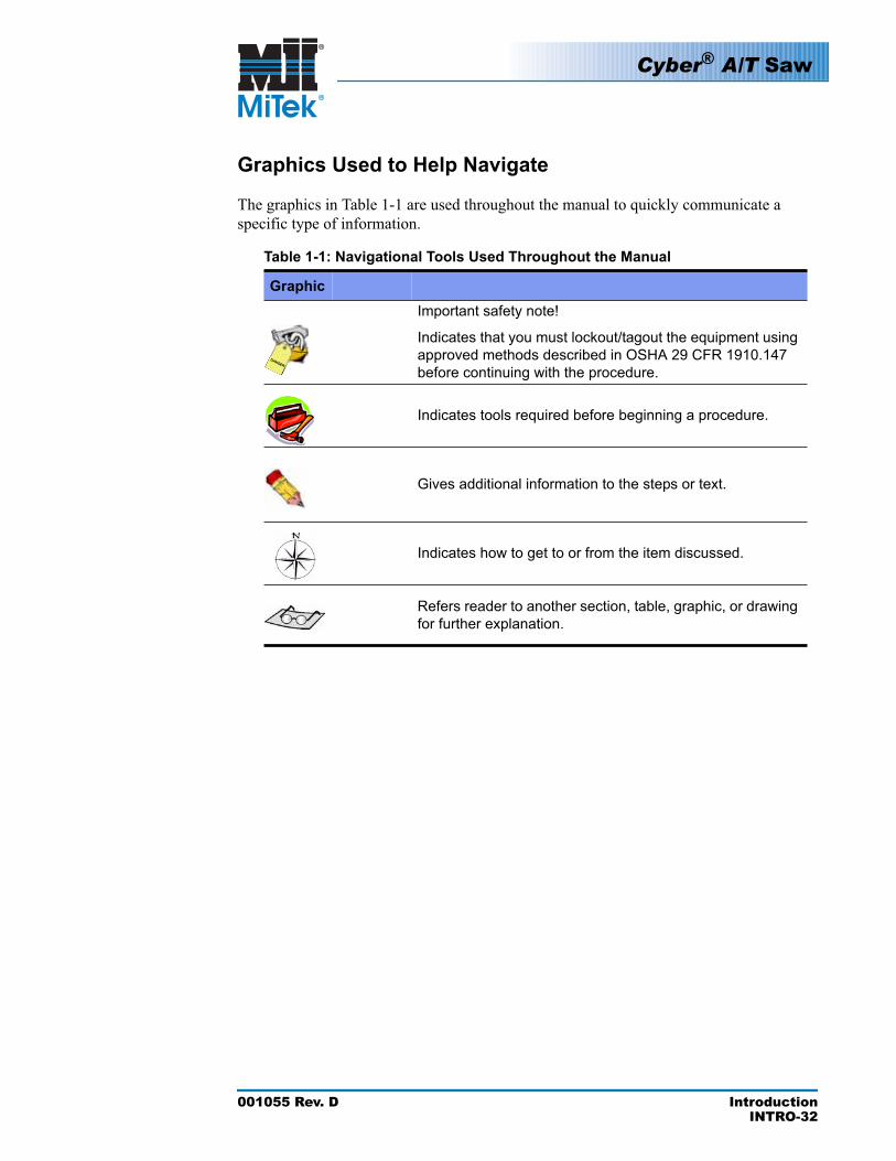
Graphic Explanation
DANGER
Important safety note!
Indicates that you must lockout/tagout the equipment using approved methods described in OSHA 29 CFR 1910.147 before continuing with the procedure.
Indicates tools required before beginning a procedure.
Gives additional information to the steps or text.
Indicates how to get to or from the item discussed.
Refers reader to another section, table, graphic, or drawing for further explanation.
Cyber® A/T Saw
001055 Rev. D IntroductionINTRO-33
Using This Manual
The Equipment Manual Set
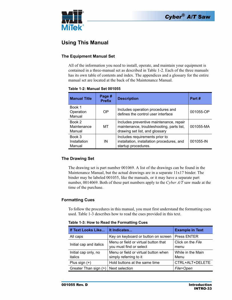
All of the information you need to install, operate, and maintain your equipment is contained in a three-manual set as described in Table 1-2. Each of the three manuals has its own table of contents and index. The appendices and a glossary for the entire manual set are located at the back of the Maintenance Manual.
Table 1-2: Manual Set 001055
Manual Title Page # Prefix Description Part #
Book 1Operation Manual
OP Includes operation procedures and defines the control user interface 001055-OP
Book 2Maintenance Manual
MTIncludes preventive maintenance, repair maintenance, troubleshooting, parts list, drawing set list, and glossary
001055-MA
Book 3Installation Manual
INIncludes requirements prior to installation, installation procedures, and startup procedures.
001055-IN
The Drawing Set
The drawing set is part number 001069. A list of the drawings can be found in the Maintenance Manual, but the actual drawings are in a separate 11x17 binder. The binder may be labeled 001055, like the manuals, or it may have a separate part number, 0014069. Both of these part numbers apply to the Cyber A/T saw made at the time of the purchase.
Formatting Cues
To follow the procedures in this manual, you must first understand the formatting cues used. Table 1-3 describes how to read the cues provided in this text
Table 1-3: How to Read the Formatting Cues
If Text Looks Like... It Indicates... Example in TextAll caps Key on keyboard or button on screen Press ENTER
Initial cap and italics Menu or field or virtual button that you must find or select
Click on the Filemenu
Initial cap only, no italics
Menu or field or virtual button when simply referring to it
While in the Main Menu
Plus sign (+) Hold buttons at the same time CTRL+ALT+DELETEGreater Than sign (>) Next selection File>Open
.
Cyber® A/T Saw
001055 Rev. D IntroductionINTRO-34
Screen Shots
Most screen shots are from Cimplicity® Project version 20.11. Screens from other Project versions may differ slightly.
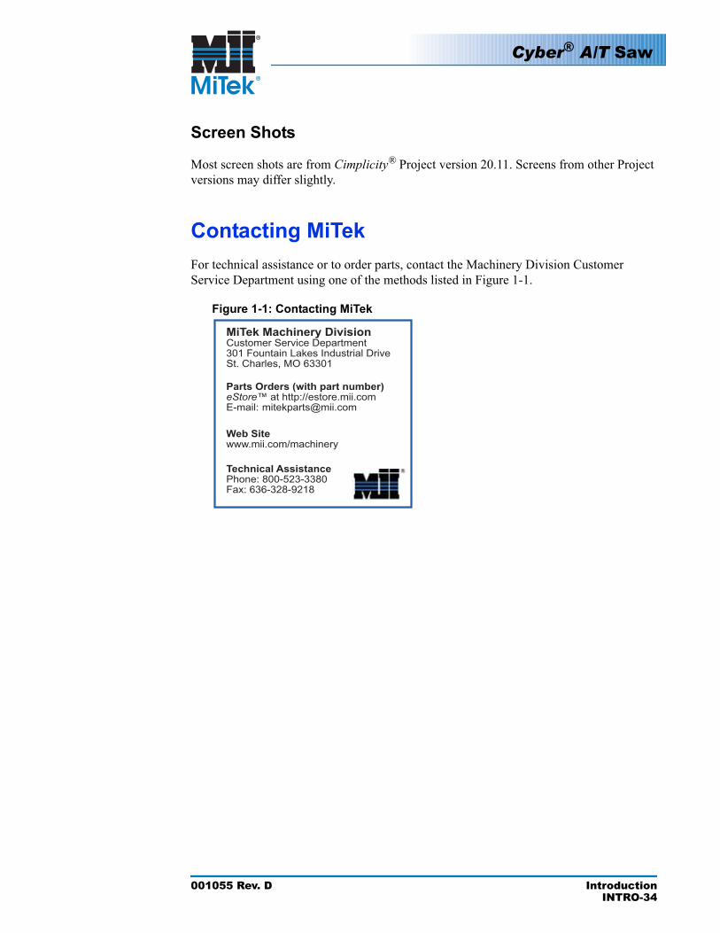
Contacting MiTekFor technical assistance or to order parts, contact the Machinery Division Customer Service Department using one of the methods listed in Figure 1-1.
Figure 1-1: Contacting MiTek
MiTek Machinery Division Customer Service Department301 Fountain Lakes Industrial DriveSt. Charles, MO 63301
Web Sitewww.mii.com/machinery
Technical AssistancePhone: 800-523-3380Fax: 636-328-9218
Parts Orders (with part number)eStore™ at http://estore.mii.comE-mail: [email protected]

001055 Rev. D Prior to InstallationIN-35
MiTek’s Responsibilities
Prior to Installation
MiTek will provide the following items and information prior to the installation date.
1. A Prior to Installation package that:
• Outlines this chapter and requests your signature of agreement.• Gives dates to expect shipment, delivery, and installation.• Explains the number of people required to help with installation.• Provides guidelines on providing an electrician, welder, and other specialists.• Describes payment information.
2. A layout (previously approved by a representative from your company) showing how the equipment should be arranged within your building.
During Installation
A MiTek Customer Service Technician (CST) will be present to oversee the installation of your equipment.
Prior to Installation
This chapter covers what you must consider or complete before this equipment can be installed.
Chapter 2
Cyber® A/T Saw
001055 Rev. D Prior to InstallationIN-36
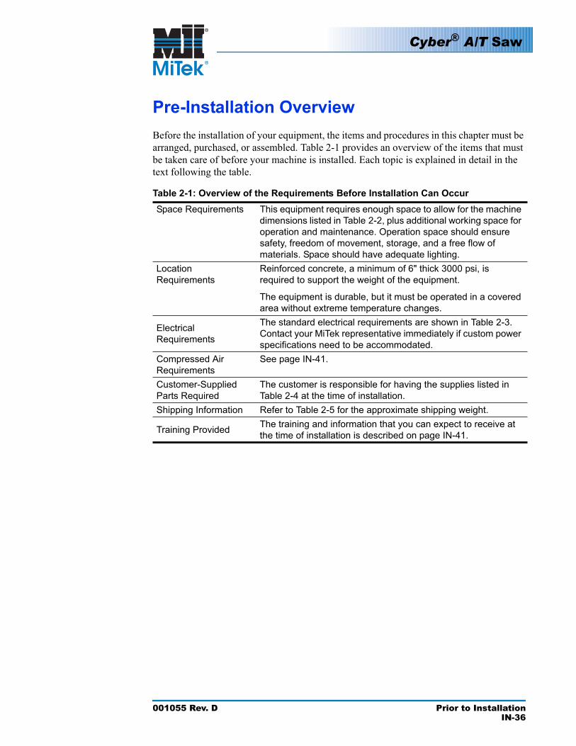
Pre-Installation OverviewBefore the installation of your equipment, the items and procedures in this chapter must be arranged, purchased, or assembled. Table 2-1 provides an overview of the items that must be taken care of before your machine is installed. Each topic is explained in detail in the text following the table.
Table 2-1: Overview of the Requirements Before Installation Can OccurSpace Requirements This equipment requires enough space to allow for the machine
dimensions listed in Table 2-2, plus additional working space for operation and maintenance. Operation space should ensure safety, freedom of movement, storage, and a free flow of materials. Space should have adequate lighting.
LocationRequirements
Reinforced concrete, a minimum of 6" thick 3000 psi, is required to support the weight of the equipment.
The equipment is durable, but it must be operated in a covered area without extreme temperature changes.
Electrical Requirements
The standard electrical requirements are shown in Table 2-3. Contact your MiTek representative immediately if custom power specifications need to be accommodated.
Compressed Air Requirements
See page IN-41.
Customer-Supplied Parts Required
The customer is responsible for having the supplies listed in Table 2-4 at the time of installation.
Shipping Information Refer to Table 2-5 for the approximate shipping weight.
Training Provided The training and information that you can expect to receive at the time of installation is described on page IN-41.
Cyber® A/T Saw
001055 Rev. D Prior to InstallationIN-37
Space RequirementsRefer to the guidelines below when planning your space allocation.
Prior to installing the Cyber A/T, a location for the saw must be selected. The location must be large enough for the saw and any accessories that may be required to operate with the saw (skatewheel outfeed conveyor, Inker, incline waste conveyor, bridge conveyor, ready-feed lumber conveyor, etc.). The saw and accessories must be placed on a concrete pad as discussed in the Location Requirements section on page IN-39.
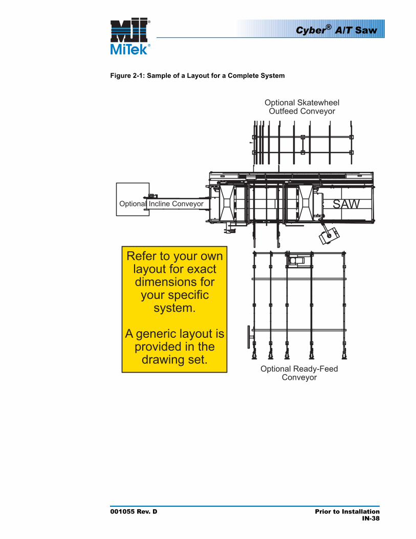
The space required for placement of equipment, safe operation of the saw and accessories, and maintenance is shown in the generic layout in the drawing set. Utility connection points are also depicted on the drawing in order to route utilities prior to receiving the saw. Figure 2-1 shows a basic arrangement of the saw and some optional equipment.
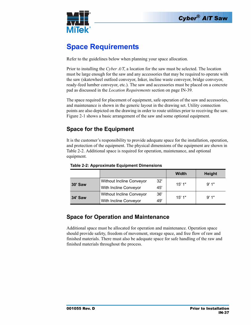
Space for the Equipment
It is the customer’s responsibility to provide adequate space for the installation, operation, and protection of the equipment. The physical dimensions of the equipment are shown in Table 2-2. Additional space is required for operation, maintenance, and optional equipment.
Table 2-2: Approximate Equipment Dimensions
Length Width Height
30' SawWithout Incline Conveyor 32'
15' 1" 9' 1"With Incline Conveyor 45'
34' SawWithout Incline Conveyor 36'
15' 1" 9' 1"With Incline Conveyor 49'
Space for Operation and Maintenance
Additional space must be allocated for operation and maintenance. Operation space should provide safety, freedom of movement, storage space, and free flow of raw and finished materials. There must also be adequate space for safe handling of the raw and finished materials throughout the process.
Cyber® A/T Saw
001055 Rev. D Prior to InstallationIN-38
Figure 2-1: Sample of a Layout for a Complete System
Optional Skatewheel Outfeed Conveyor
Optional Ready-Feed Conveyor
Optional Incline Conveyor SAW
Refer to your own layout for exact dimensions for your specific
system.
A generic layout is provided in the
drawing set.
Cyber® A/T Saw
001055 Rev. D Prior to InstallationIN-39
Location Requirements
Floor Structure
A level and structurally sound concrete slab must be provided for the installation of the equipment. This slab should be designed and installed in accordance with local building code requirements. Concrete should reinforced, a minimum of 6 in. thick, and 3000 psi. Refer to your layout drawing for placement of concrete.
Environment
The electrical enclosures are NOT for outdoor use. The equipment should be operated only in a covered, dry area without extreme temperature changes. Under no circumstances should the electrical enclosures be sprayed with water. Lighting should be adequate for safe operation and maintenance.
Electrical Requirements
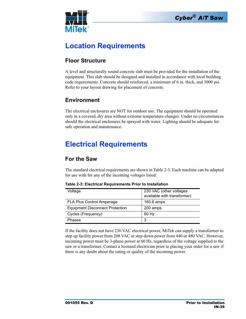
For the Saw
The standard electrical requirements are shown in Table 2-3. Each machine can be adapted for use with for any of the incoming voltages listed.
Table 2-3: Electrical Requirements Prior to InstallationVoltage 230 VAC (other voltages
available with transformer)FLA Plus Control Amperage 160.6 ampsEquipment Disconnect Protection 200 ampsCycles (Frequency) 60 HzPhases 3
If the facility does not have 230 VAC electrical power, MiTek can supply a transformer to step up facility power from 208 VAC or step down power from 440 or 480 VAC. However, incoming power must be 3-phase power at 60 Hz, regardless of the voltage supplied to the saw or a transformer. Contact a licensed electrician prior to placing your order for a saw if there is any doubt about the rating or quality of the incoming power.
WARNING
ELECTROCUTION HAZARD!
High voltage power is deadly. Only qualified electricians should perform any installation or maintenance involving electrical power provided to the saw.
Cyber® A/T Saw
001055 Rev. D Prior to InstallationIN-40
When using a transformer to provide 230 VAC to the saw, wire the transformer in accordance with manufacturer’s specification (provided with the transformer), in order to have 230 VAC on the output side of the transformer.
Power to the saw must be provided through an electrical disconnect rated for the required incoming power and installed in accordance with all governing electrical codes. It must be installed by a qualified, licensed electrician.
Power connections at the saw are made through the top of the stationary-end electrical enclosure. Provide a suitable knockout through the enclosure for the power wires. Electrical connection will require four wires including a grounded conductor.
CAUTIONFailure to provide the rated electrical power within the allowed tolerance will cause excessive motor faults and, possibly, premature motor failure. Incoming power must be balanced and free of harmonic distortion. Consult a licensed electrician or your power provider to ensure power requirements are available and adequate.
For the PC Enclosure
WARNING
ELECTROCUTION HAZARD!
All electrical work must be performed by a qualified electrician and must conform to all governing electrical codes.
Do not turn on electrical power until you have completed the entire procedure.
Follow approved lockout and tagout procedures (OSHA 29 CFR 1910.147).
Provide a 120 VAC protected electrical circuit that is separate from the saw’s power circuit. The wiring will terminate at the terminal blocks labeled Power In on Drawing 90503 as described later in this procedure. Follow all applicable electrical standards and codes.
!
!
Quick disconnect fittings are not recommended because they reduce air flow, which could reduce the response time of the pneumatic blade brakes.
Cyber® A/T Saw
001055 Rev. D Prior to InstallationIN-41
Compressed Air RequirementsThe saw compressed air connection is a 1/4-in. NPT female port located on the filter-regulator-lubricator (FRL) assembly mounted to the left of the stationary electrical enclosure. Connections can be hard piped to the FRL port. However, for ease of installation, it is recommended that a hose and a hose barb be used to make the final connection to the FRL assembly. This will provide some flexibility in the final placement of the saw.
Minimum pneumatic pressure required: 10 scfm @ 100 psi
WARNING
PNEUMATIC PRESSURE HAZARD.
Compressed air lines should be installed only by qualified personnel familiar with all governing regulations. Failure to use proper materials and installation practices can result in ruptured lines leading to personal injury, equipment damage, and equipment failure.
CAUTIONFailure to provide the required compressed air will prevent the saw from operating. Compressed air supply must never drop below 80 psi. Other demands on the compressed air supply due to other equipment in the facility will cause the compressed air supply to fluctuate. Ensure the air supply remains above 80 psi when other facility equipment is operating.
!
Cyber® A/T Saw
001055 Rev. D Prior to InstallationIN-42
Customer-Supplied Parts RequiredThe customer must supply the parts shown in Table 2-4. Some must be installed before installation of the saw and some must be available for use at the time of installation.
Table 2-4: Customer-Supplied Parts
Item WhenNeeded Description
Prior to installation date
Air compressor and supply line that meets the requirements on page IN-41
Connector for tube from air source to 1/4" NPT port on the air regulator
Electrical Equipment
Prior to and during installation
All electrical requirements to provide power to the disconnect enclosure are the customer’s responsibility
Transport Equipment At delivery Forklift, chains, and spreader bars capable of carrying
the weight indicated in Table 2-5.
Tools That May Need to be Rented
During installation
Transit with measuring stick
Industrial hammer-drill and 1/2"x12" masonry bit
Shipping InformationTable 2-5 shows the weight of a standard saw. Optional equipment is not included in the weight. The weight of saws that are different lengths than what is listed in Table 2-5 will vary.
Table 2-5: Shipping Information for Saw
Contents of Shipment Weight30' Saw Approx. 18,000 lb
Training ProvidedIf MiTek is overseeing the installation of your equipment, the MiTek representative trains your operators and maintenance personnel on the equipment’s proper operation and maintenance. The representative explains the warranty policy, gives an overview of the equipment manual, and requests your signature that the manual was received. Starting with revision D, the manual is a multi-volume set.
Compressed Air

001055 Rev. D InstallationIN-43
Responsibilities During InstallationMiTek will provide installation supervision to ensure that the system is installed properly and operates correctly. We will also provide operating and maintenance training at the time the equipment is installed. You, as the customer, are responsible for providing all labor and equipment needed to complete the installation. These requirements are explained in the Prior to Installationchapter.
Installation procedures, including the Installation Checklist, should be reviewed and followed during installation of the saw and whenever the saw is moved. Due to vibration caused by operation of the saw, it may become necessary to recheck some features of the saw using procedures found in this chapter and throughout this manual set.
Installation
This chapter describes the entire installation process in detail. It assumes that the prior-to-installation requirements are satisfied.
Chapter 3
Cyber® A/T Saw
001055 Rev. D InstallationIN-44
Delivery
Responsibilities During Delivery
CRUSH HAZARD.
Failure to lift the saw in the prescribed manner may cause serious injury, including death, or equipment damage. Never lift the saw with one forklift truck!
Personnel not involved in the off-loading of the truck and placement of the saw shall remain clear of the area.
Even if a MiTek representative is present, it is the customer’s responsibility to provide equipment and labor for unloading, placement, and wiring of the equipment. Exercise extreme caution to avoid damage or misalignment during unloading. Do not apply pressure on any moving parts or fittings.
A heavy-duty forklift or truck wrecker is required to move the equipment during unloading and placement of the machine. The lifting equipment must be rated appropriately for the weights shown in Table 2-5 on page IN-42.
Checking for Damage
All shipments from MiTek are covered with tarps. When your shipment arrives, check to ensure that the tarps are in place. Displaced tarps may indicate a potential problem.
After removing the tarps, inspect the shipment for water/moisture, debris, and damage. Report any findings as required by the transport company. Document any findings by taking photographs or a video. Note any and all damage to the saw on the truck bill of lading to ensure proper documentation for insurance claims. Without this note, any damage in transit is the responsibility of the customer to repair.
Notify MiTek Machinery Division Customer Service of any unacceptable findings discovered during the receipt inspection. Although your findings may not appear to be a problem, they may cause premature failure of components, poor performance, or erratic performance.
Do not remove straps used to hold the saw to the tractor trailer until the truck is positioned as close as possible to area in which the equipment will be installed. If possible, position the truck so that the saw can be lifted, and the truck can be driven out from under the saw.
Once the tractor trailer is in position, remove the shipping straps.
WARNING
!
Cyber® A/T Saw
001055 Rev. D InstallationIN-45
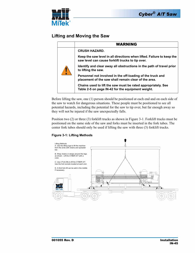
Lifting and Moving the Saw
WARNINGCRUSH HAZARD.
Keep the saw level in all directions when lifted. Failure to keep the saw level can cause forklift trucks to tip over.
Identify and clear away all obstructions in the path of travel prior to lifting the saw.
Personnel not involved in the off-loading of the truck and placement of the saw shall remain clear of the area.
Chains used to lift the saw must be rated appropriately. See Table 2-5 on page IN-42 for the equipment weight.
Before lifting the saw, one (1) person should be positioned at each end and on each side of the saw to watch for dangerous situations. These people must be positioned to see all potential hazards, including the potential for the saw to tip over, but far enough away so they will not be injured if the saw unexpectedly falls.
Position two (2) or three (3) forklift trucks as shown in Figure 3-1. Forklift trucks must be positioned on the same side of the saw and forks must be inserted in the fork tubes. The center fork tubes should only be used if lifting the saw with three (3) forklift trucks.
Figure 3-1: Lifting Methods
Lifting Methods
A. Use the lifting lugs to lift the machine from the ends with chains and spreader
bar.
B. Wrap chains or straps around the legsas shown . Lift the CYBER A/T with a
crain.
C. Use 2 Fork lifts to lift the CYBER A/T.
Use the fork tunnels located at each end.
D. A third fork lift can be add in the middle
if necessary.
!
Cyber® A/T Saw
001055 Rev. D InstallationIN-46
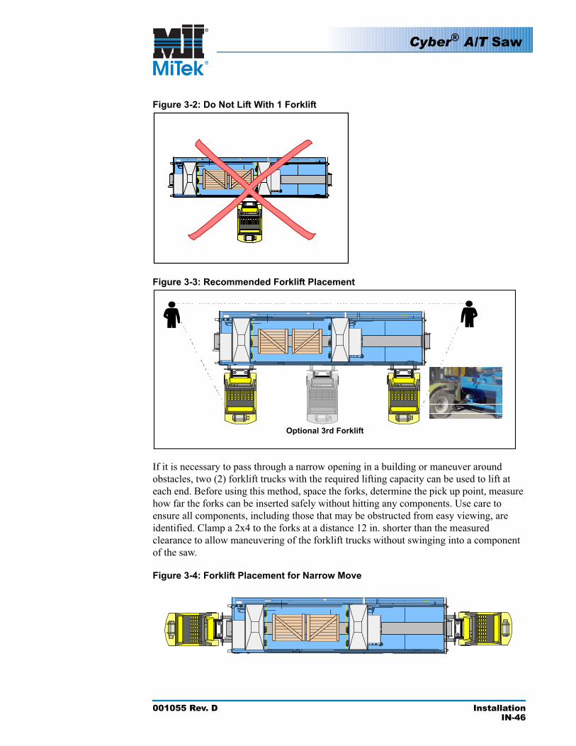
Figure 3-2: Do Not Lift With 1 Forklift
Figure 3-3: Recommended Forklift Placement
If it is necessary to pass through a narrow opening in a building or maneuver around obstacles, two (2) forklift trucks with the required lifting capacity can be used to lift at each end. Before using this method, space the forks, determine the pick up point, measure how far the forks can be inserted safely without hitting any components. Use care to ensure all components, including those that may be obstructed from easy viewing, are identified. Clamp a 2x4 to the forks at a distance 12 in. shorter than the measured clearance to allow maneuvering of the forklift trucks without swinging into a component of the saw.
Figure 3-4: Forklift Placement for Narrow Move
Cyber® A/T Saw
001055 Rev. D InstallationIN-47
Avoid dips and bumps that will cause the saw to be carried out of level. Do not carry the saw over ditches or large bumps that require the use of planking or other material to cross over. Planning your path, especially if lifting from the ends, is important. You must determine how you will swing into a building if you cannot move straight through the opening. Before passing under an overhead obstruction, check the lifted height of the saw and the height of the obstruction before passing under the obstruction. Before passing through an opening, plan your path and measure the opening’s width and height and the width and height of the saw.
Installation
Installing the Saw
Each component must be located in specific locations. A sample layout is shown on page IN-38, but refer to your own layout during installation. Your MiTek representative will provide your layout to you before the equipment is installed.
1. Using the lifting method described in the Delivery section, place the saw in the desired location for installation.
2. Unpack the equipment.
a) Remove the crate from the waste conveyor so that items can be identified and located easily.
b) Remove the touch screen monitor box (labeled CTC) and set it aside in a safe location.
c) Remove components strapped to the outside of the crate.
d) Remove components from the crate and layout so that items can be identified and located easily.
e) Remove packing material from dust hoods.
3. Assemble lumber stop components (refer to Drawings 77802 and 60005).
a) Locate the lumber stop weldment (PN 77435) with mounted gear racks and gearbox (underside) among the items that were removed from the crate.
b) Locate the lumber fence weldment (PN 77366) among the items that were removed from the crate.
c) Locate the lumber stop guard (PN 79805) among the items that were removed from the crate.
Cyber® A/T Saw
001055 Rev. D InstallationIN-48
d) Locate the lumber stop pointer (PN 77804) among the items that were removed from the crate.
e) Remove four hex head cap screws (PN 327357) and lock spring washers (PN 364050) from the saw frame where the lumber stop weldment will be mounted.
f) Mount the lumber stop weldment to the saw frame using the four screws and lock spring washers.
g) Remove two hex head cap screws (PN 327363), lock spring washers (PN 364050) and flat washers (PN 365134) from the ends of the gear racks.
h) Mount the lumber stop fence weldment to the ends of the gear racks using the two hex head cap screws, lock spring washers, and flat washers.
i) Mount the lumber stop guard using three 1/4-in. lock washers (PN 364034) and 1/4-20 x 5/8 long bolts (PN 327155).
j) Remove two socket head cap screws (PN 326153), lock spring washers (PN 364064), and flat washers (PN 365115) from the lumber fence weldment (between the hex head cap screws).
k) Loosely mount the lumber stop pointer to the lumber fence weldment using the two socket head cap screws, lock spring washers, and flat washers.The final position of the pointer will be determined during system calibration.
l) Remove the banding holding the lumber stop motor assembly (PN 60165-511) to the saw frame fork tube.
m) Remove the packaging around the motor assembly. Be careful not to lose the coupling spider insert (PN 557392).
n) Remove four hex head cap screws (PN 327155) and lock washers (PN 364034) from the motor assembly mounting flange.
o) Mount the motor assembly by placing the spider coupling insert on the motor coupling hub, aligning the coupling insert with the coupling mounted to the gearbox on the underside of the lumber stop weldment, and securing the motor assembly to the lumber stop motor mounting bracket using the four screws and lock washers. (The screws pass through the mounting bracket and thread into the motor assembly mounting flange.)
p) Connect the loose proximity switch cable to the proximity switch mounted on the motor assembly mounting bracket.
Cyber® A/T Saw
001055 Rev. D InstallationIN-49
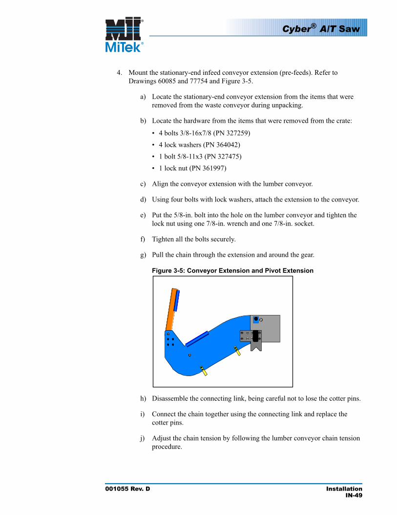
4. Mount the stationary-end infeed conveyor extension (pre-feeds). Refer to Drawings 60085 and 77754 and Figure 3-5.
a) Locate the stationary-end conveyor extension from the items that were removed from the waste conveyor during unpacking.
b) Locate the hardware from the items that were removed from the crate:
• 4 bolts 3/8-16x7/8 (PN 327259)• 4 lock washers (PN 364042)• 1 bolt 5/8-11x3 (PN 327475)• 1 lock nut (PN 361997)
c) Align the conveyor extension with the lumber conveyor.
d) Using four bolts with lock washers, attach the extension to the conveyor.
e) Put the 5/8-in. bolt into the hole on the lumber conveyor and tighten the lock nut using one 7/8-in. wrench and one 7/8-in. socket.
f) Tighten all the bolts securely.
g) Pull the chain through the extension and around the gear.
Figure 3-5: Conveyor Extension and Pivot Extension
h) Disassemble the connecting link, being careful not to lose the cotter pins.
i) Connect the chain together using the connecting link and replace the cotter pins.
j) Adjust the chain tension by following the lumber conveyor chain tension procedure.

Cyber® A/T Saw
001055 Rev. D InstallationIN-50
5. Install the stationary-end lumber pivot extension (PN 77407). Refer to Drawing 77754 and Figure 3-5.
a) Locate the stationary-end lumber pivot extension among the items that were removed from the crate.
b) Locate the hardware among the items that were removed from the crate:
• Shoulder screw (PN 328089)• Lock nut (PN 361990)
c) Align the pivot extension in the conveyor extension and secure with the shoulder screw and lock nut.
6. Mount the carriage-end infeed conveyor extension (pre-feeds). Refer to Drawings 60085 and 77765.
7. Locate the carriage-end infeed conveyor extension from the items that were removed from the waste conveyor during unpacking conveyor extension
a) Locate the hardware from the items that were removed from the crate:
• 4 bolts 3/8-16x7/8 (PN 327259)• 4 lock washers (PN 364042)• 1 bolt 5/8-11x3 (PN 327475)• 1 lock nut (PN 361997)
b) Align the conveyor extension with the lumber conveyor.
c) Using four bolts with lock washers, attach the extension to the conveyor.
d) Put the 5/8-in. bolt into the hole on the lumber conveyor and tighten the lock nut using a 7/8-in. wrench and a 7/8-in. socket.
e) Tighten all the bolts securely.
f) Pull the chain through the extension and around the gear.
g) Disassemble the connecting link, being careful not to lose the cotter pins.
h) Align the pushers to the stationary side.
i) Connect the chain together using the connecting link and replace the cotter pins.
j) Adjust the chain tension by following the instructions in the Adjusting the Infeed Conveyor Chain Tension section in the Maintenance Manual.
Cyber® A/T Saw
001055 Rev. D InstallationIN-51
8. Install the carriage-end lumber pivot extension (PN 77292-501) with the Easyfeed lumber roller assembly (PN 79782). Refer to drawings 77765 and 60005.
a) Locate the stationary-end lumber pivot extension from the items that were removed from the crate.
b) Locate the hardware from the items that were removed from the crate:
• Shoulder screw (PN 328089)• Lock washer (PN 361990)
c) Align the pivot extension with the conveyor extension and secure with the shoulder screw and lock washer.
9. Install the stationary operator guard (PN 77467), guard tube weldment (PN 77920) and attached guard mounting pad assembly (PN 77921). Refer to Drawing 60120.
a) Locate the stationary operator guard.
b) Locate the hardware:
• 4 cap screws 3/8-16x3/4 (PN 327257) (for the frame)• 4 lock washers 3/8-in. (PN 364042) (for the frame)• 4 flat washers 3/8-in. (PN 365124) (for the frame)• 4 hex head cap screws 3/8-16x3/4 (PN 327257) (for the conveyor
extension)• 4 lock washers 3/8-in. (PN 364042) (for the conveyor extension)
c) Mount the stationary operator guard to the saw frame using the four screws and lock spring washers.
d) Mount the guard tube weldment to the conveyor extension using the four screws and lock spring washers.
e) Tighten securely.
10. Install the Easyfeed operator guard weldment (PN 77952), guard tube weldment (PN 77920), and attached guard mounting pad assembly (PN 77921). Refer to drawing 60120.
a) Locate the carriage operator guard from the items removed from the machine.
b) Locate the hardware. The hardware will be in the holes where the guard will mount.
• 4 cap screws 3/8-16x3/4 (PN 327257) (for the frame)
Cyber® A/T Saw
001055 Rev. D InstallationIN-52
• 4 lock washers 3/8-in. (PN 364042) (for the frame)• 4 flat washers 3/8-in. (PN 365124) (for the frame)• 4 hex head cap screws 3/8-16x3/4 (PN 327257) (for the conveyor
extension)• 4 lock washers 3/8-in.(PN 364042) (for the conveyor extension)
c) Mount the stationary operator guard to the saw frame using the four screws and lock spring washers.
d) Mount the guard tube weldment to the conveyor extension using the four screws and lock spring washers.
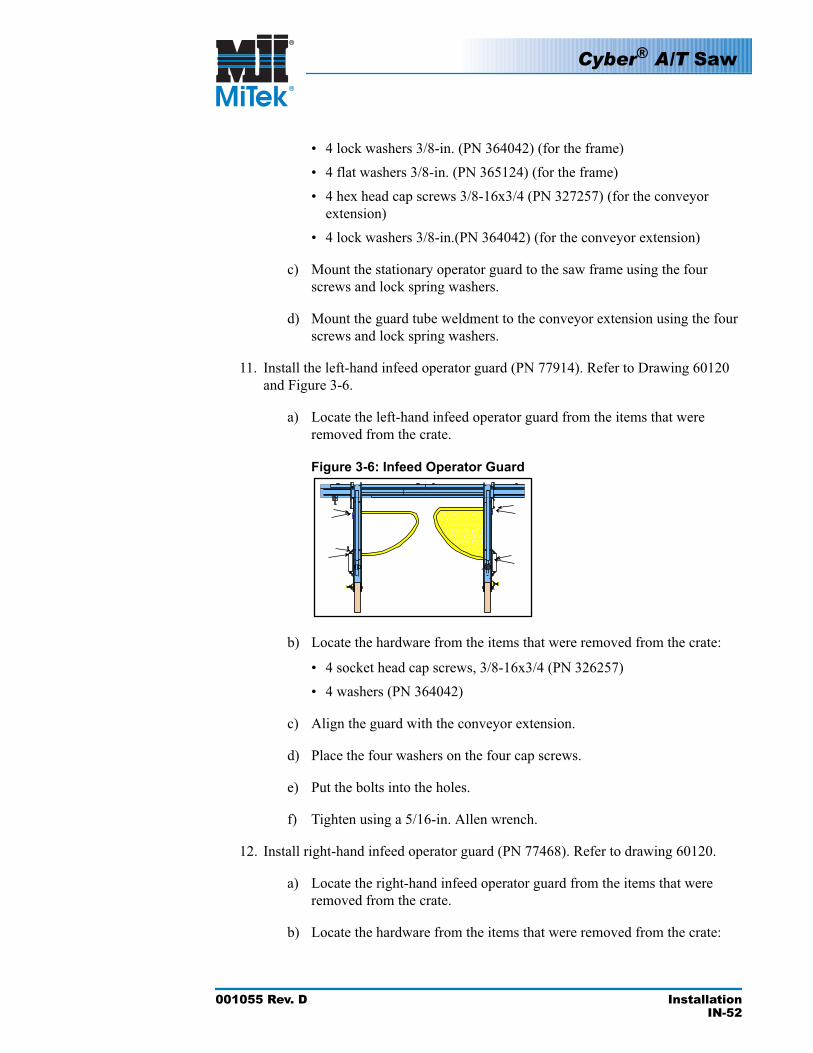
11. Install the left-hand infeed operator guard (PN 77914). Refer to Drawing 60120 and Figure 3-6.
a) Locate the left-hand infeed operator guard from the items that were removed from the crate.
Figure 3-6: Infeed Operator Guard
b) Locate the hardware from the items that were removed from the crate:
• 4 socket head cap screws, 3/8-16x3/4 (PN 326257)• 4 washers (PN 364042)
c) Align the guard with the conveyor extension.
d) Place the four washers on the four cap screws.
e) Put the bolts into the holes.
f) Tighten using a 5/16-in. Allen wrench.
12. Install right-hand infeed operator guard (PN 77468). Refer to drawing 60120.
a) Locate the right-hand infeed operator guard from the items that were removed from the crate.
b) Locate the hardware from the items that were removed from the crate:
Cyber® A/T Saw
001055 Rev. D InstallationIN-53
• 4 socket head cap screws 3/8-16x3/4 (PN 326257)• 4 washers (PN 364042)
c) Align the guard to the conveyor extension.
d) Place the four washers on the four cap screws.
e) Put the bolts into the holes.
f) Tighten using a 5/16-in. Allen wrench.
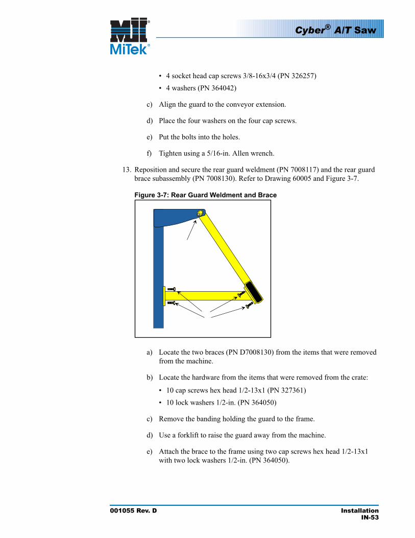
13. Reposition and secure the rear guard weldment (PN 7008117) and the rear guard brace subassembly (PN 7008130). Refer to Drawing 60005 and Figure 3-7.
Figure 3-7: Rear Guard Weldment and Brace
a) Locate the two braces (PN D7008130) from the items that were removed from the machine.
b) Locate the hardware from the items that were removed from the crate:
• 10 cap screws hex head 1/2-13x1 (PN 327361)• 10 lock washers 1/2-in. (PN 364050)
c) Remove the banding holding the guard to the frame.
d) Use a forklift to raise the guard away from the machine.
e) Attach the brace to the frame using two cap screws hex head 1/2-13x1 with two lock washers 1/2-in. (PN 364050).
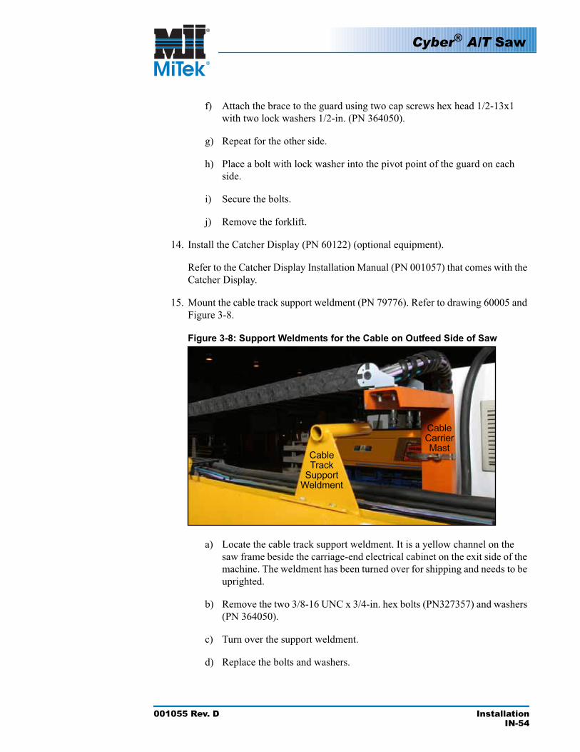
Cyber® A/T Saw
001055 Rev. D InstallationIN-54
f) Attach the brace to the guard using two cap screws hex head 1/2-13x1 with two lock washers 1/2-in. (PN 364050).
g) Repeat for the other side.
h) Place a bolt with lock washer into the pivot point of the guard on each side.
i) Secure the bolts.
j) Remove the forklift.
14. Install the Catcher Display (PN 60122) (optional equipment).
Refer to the Catcher Display Installation Manual (PN 001057) that comes with the Catcher Display.
15. Mount the cable track support weldment (PN 79776). Refer to drawing 60005 and Figure 3-8.
Figure 3-8:
CableTrack
SupportWeldment
CableCarrierMast
Support Weldments for the Cable on Outfeed Side of Saw
a) Locate the cable track support weldment. It is a yellow channel on the saw frame beside the carriage-end electrical cabinet on the exit side of the machine. The weldment has been turned over for shipping and needs to be uprighted.
b) Remove the two 3/8-16 UNC x 3/4-in. hex bolts (PN327357) and washers (PN 364050).
c) Turn over the support weldment.
d) Replace the bolts and washers.
Cyber® A/T Saw
001055 Rev. D InstallationIN-55
e) Tighten securely.
16. Mount the cable carrier mast (PN 7035000) with the cable carrier attached (refer to drawing 60005).
a) Locate the cable carrier on top of the movable carriage next to the support weldment.
b) The support weldment has a bracket to which the cable track connects.
c) Connect the track to the brace by inserting the track into the brace until it snaps in place.
17. Secure the cable bundle to the cable carrier mast subassembly using a swivel lock hose clamp (PN 778068) as shown in Figure 3-8.
CAUTION
Failure to adequately secure the cable bundle that exits the moving end of the cable carrier may result in cables snagging when the carriage moves. This can lead to broken cables and damage to other parts of the saw.
18. Install the emergency stop perimeter cable components. Refer to drawings 60120 and 90500.
a) Locate the hardware from the items that were removed from the crate:
• 1 Bracket (PN 7044300) with 1 eye bolt (PN 358088) attached • 2 cap screws 3/8-16x3/4 (PN 327257)• 2 lock washers 3/8-in. (PN 364042)• 2 eye bolts 3/4-3/8x4 (PN 358087)• 1 Thimble 3/16-in. wire (PN 271026)
b) Install the two (2) eye bolts (PN 358087) into the rear guard. Adjust the height to 3 in.
c) Secure by tightening the jam nuts.
d) Attach the bracket to the rear guard with the eye bolt loop toward the movable carriage side using the two 3/8-16x3/4 bolts with 3/8-in. lock washers.
e) Attach the pulley to the back guard on the movable end using the hardware in the holes.
!
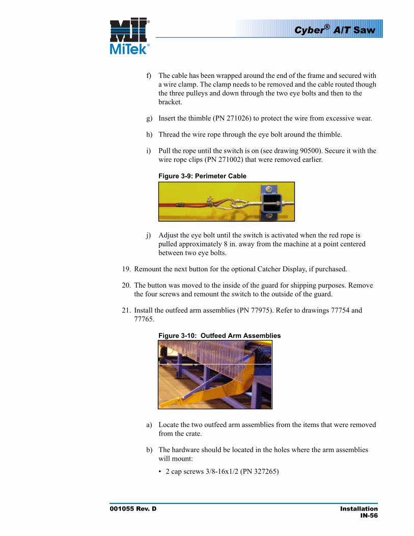
Cyber® A/T Saw
001055 Rev. D InstallationIN-56
f) The cable has been wrapped around the end of the frame and secured with a wire clamp. The clamp needs to be removed and the cable routed though the three pulleys and down through the two eye bolts and then to the bracket.
g) Insert the thimble (PN 271026) to protect the wire from excessive wear.
h) Thread the wire rope through the eye bolt around the thimble.
i) Pull the rope until the switch is on (see drawing 90500). Secure it with the wire rope clips (PN 271002) that were removed earlier.
Figure 3-9: Perimeter Cable
j) Adjust the eye bolt until the switch is activated when the red rope is pulled approximately 8 in. away from the machine at a point centered between two eye bolts.
19. Remount the next button for the optional Catcher Display, if purchased.
20. The button was moved to the inside of the guard for shipping purposes. Remove the four screws and remount the switch to the outside of the guard.
21. Install the outfeed arm assemblies (PN 77975). Refer to drawings 77754 and 77765.
Figure 3-10: Outfeed Arm Assemblies
a) Locate the two outfeed arm assemblies from the items that were removed from the crate.
b) The hardware should be located in the holes where the arm assemblies will mount:
• 2 cap screws 3/8-16x1/2 (PN 327265)

Cyber® A/T Saw
001055 Rev. D InstallationIN-57
• 4 cap screws 3/8-16x1 (PN 327261)• 6 lock washers 3/8-in (PN 364042)
c) Align the outfeed arm assemblies so that the bar is to the outside of the machine.
d) Use one (1) of the 3/8-16x1/2 cap screws with one (1) 3/8-in. lock washer in the top hole of the assembly.
e) Use two (2) of the 3/8-16 x 1 cap screws with two (2) 3/8 lock washers in the middle and bottom holes of the assembly.
f) Repeat for the other side.
22. Level the saw.
If the saw is installed in a new building or on a new concrete pad, levelness of the saw should be rechecked every six (6) months for two (2) years. Settling of the concrete can cause the saw to become out of level, resulting in mis-cut boards.
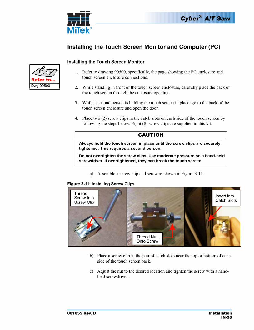
Cyber® A/T Saw
001055 Rev. D InstallationIN-58
Installing the Touch Screen Monitor and Computer (PC)
Installing the Touch Screen Monitor
1. Refer to drawing 90500, specifically, the page showing the PC enclosure and touch screen enclosure connections.Refer to...
Dwg 90500 2. While standing in front of the touch screen enclosure, carefully place the back of the touch screen through the enclosure opening.
3. While a second person is holding the touch screen in place, go to the back of the touch screen enclosure and open the door.
4. Place two (2) screw clips in the catch slots on each side of the touch screen by following the steps below. Eight (8) screw clips are supplied in this kit.
CAUTIONAlways hold the touch screen in place until the screw clips are securely tightened. This requires a second person.
Do not overtighten the screw clips. Use moderate pressure on a hand-held screwdriver. If overtightened, they can break the touch screen.
a) Assemble a screw clip and screw as shown in Figure 3-11.
Figure 3-11: Installing Screw Clips
Insert Into Catch Slots
ThreadScrew Into Screw Clip
Thread Nut Onto Screw
b) Place a screw clip in the pair of catch slots near the top or bottom of each side of the touch screen back.
c) Adjust the nut to the desired location and tighten the screw with a hand-held screwdriver.
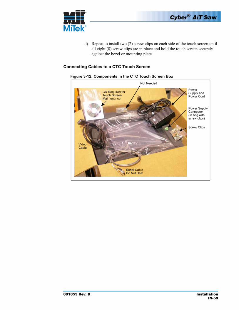
Cyber® A/T Saw
001055 Rev. D InstallationIN-59
d) Repeat to install two (2) screw clips on each side of the touch screen until all eight (8) screw clips are in place and hold the touch screen securely against the bezel or mounting plate.
Connecting Cables to a CTC Touch Screen
Figure 3-12: Components in the CTC Touch Screen Box
PowerSupply and Power Cord
Power Supply Connector(In bag with screw clips)
Screw Clips
Serial Cable- Do Not Use!
Video Cable
CD Required for Touch Screen Maintenance
Not Needed
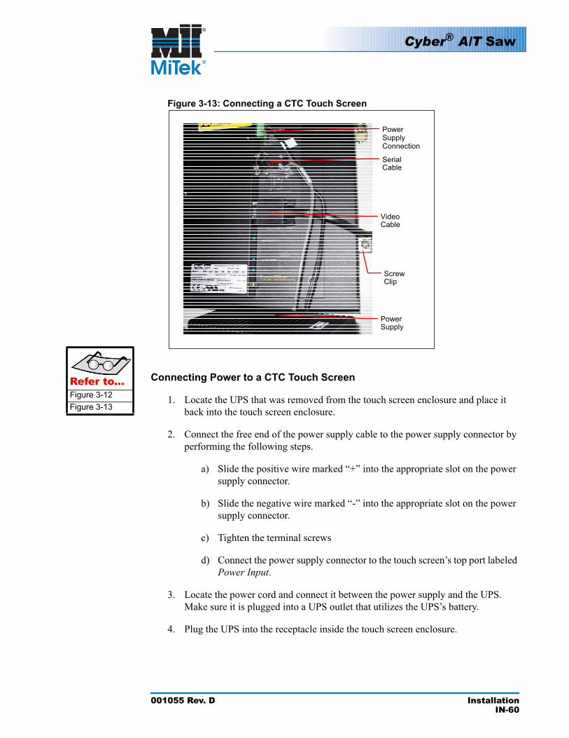
Cyber® A/T Saw
001055 Rev. D InstallationIN-60
Figure 3-13: Connecting a CTC Touch Screen
Screw Clip
Video Cable
Power Supply Connection
Serial Cable
Power Supply
Refer to...Figure 3-12Figure 3-13
Connecting Power to a CTC Touch Screen
1. Locate the UPS that was removed from the touch screen enclosure and place it back into the touch screen enclosure.
2. Connect the free end of the power supply cable to the power supply connector by performing the following steps.
a) Slide the positive wire marked “+” into the appropriate slot on the power supply connector.
b) Slide the negative wire marked “-” into the appropriate slot on the power supply connector.
c) Tighten the terminal screws
d) Connect the power supply connector to the touch screen’s top port labeled Power Input.
3. Locate the power cord and connect it between the power supply and the UPS. Make sure it is plugged into a UPS outlet that utilizes the UPS’s battery.
4. Plug the UPS into the receptacle inside the touch screen enclosure.
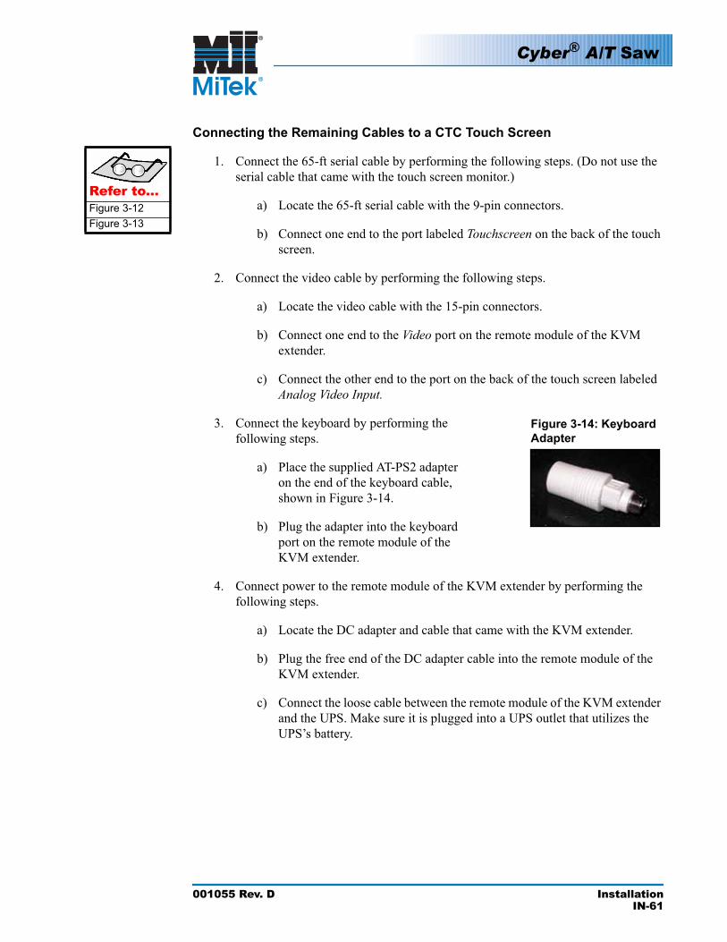
Refer to...Figure 3-12Figure 3-13
Cyber® A/T Saw
001055 Rev. D InstallationIN-61
Connecting the Remaining Cables to a CTC Touch Screen
1. Connect the 65-ft serial cable by performing the following steps. (Do not use the serial cable that came with the touch screen monitor.)
a) Locate the 65-ft serial cable with the 9-pin connectors.
b) Connect one end to the port labeled Touchscreen on the back of the touch screen.
2. Connect the video cable by performing the following steps.
a) Locate the video cable with the 15-pin connectors.
b) Connect one end to the Video port on the remote module of the KVM extender.
c) Connect the other end to the port on the back of the touch screen labeled Analog Video Input.
3. Connect the keyboard by performing the following steps.
Figure 3-14: Keyboard Adapter
a) Place the supplied AT-PS2 adapter on the end of the keyboard cable, shown in Figure 3-14.
b) Plug the adapter into the keyboard port on the remote module of the KVM extender.
4. Connect power to the remote module of the KVM extender by performing the following steps.
a) Locate the DC adapter and cable that came with the KVM extender.
b) Plug the free end of the DC adapter cable into the remote module of the KVM extender.
c) Connect the loose cable between the remote module of the KVM extender and the UPS. Make sure it is plugged into a UPS outlet that utilizes the UPS’s battery.
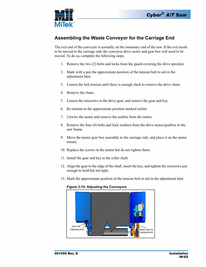
Cyber® A/T Saw
001055 Rev. D InstallationIN-62
Assembling the Waste Conveyor for the Carriage End
The exit end of the conveyor is normally on the stationary end of the saw. If the exit needs to be moved to the carriage end, the conveyor drive motor and gear box will need to be moved. To do so, complete the following steps.
1. Remove the two (2) bolts and locks from the guard covering the drive sprocket.
2. Mark with a pen the approximate position of the tension bolt to aid in the adjustment later.
3. Loosen the belt tension until there is enough slack to remove the drive chain.
4. Remove the chain.
5. Loosen the setscrews in the drive gear, and remove the gear and key.
6. Re-tension to the approximate position marked earlier.
7. Unwire the motor and remove the sealtite from the motor.
8. Remove the four (4) bolts and lock washers from the drive motor/gearbox to the saw frame.
9. Move the motor gear box assembly to the carriage side, and place it on the motor mount.
10. Replace the screws in the motor but do not tighten them.
11. Install the gear and key to the roller shaft.
12. Align the gear to the edge of the shaft, insert the key, and tighten the setscrews just enough to hold but not tight.
13. Mark the approximate position of the tension bolt to aid in the adjustment later.
Figure 3-15: Adjusting the Conveyors
Cyber® A/T Saw
001055 Rev. D InstallationIN-63
14. Loosen the belt tensioning bolt until the chain can be installed on the gear.
15. Install the chain and re-tension the roller to the approximate position marked earlier.
16. Align the motor so that the chain is straight between the two gears. You may need to adjust the gear in or out slightly to get good alignment. Tighten the setscrews in the gear.
17. Adjust the motor back until there is one (1) chain link of movement in the chain when pressed midway between the gears, then tighten the bolts.
18. Align the guard to the outside gear where it not touching the chain, and clamp it in place.
19. Drill a 11/64-in. hole, tap to 1/4-20, then install the bolts.
20. Have a certified electrician wire the motor per local codes.
a) Install two (2) customer-supplied junction boxes on the outfeed of the saw. One convenient to the Sealtite used for the previous location and one at the new location.
b) Run a conduit between the junction boxes.
c) Pull wire through the conduit.
d) Connect the Sealtite to the junction boxes at both ends.
e) Wire the connections in the junction boxes and to the motor.
Refer to...Dwg. 7022100
Cyber® A/T Saw
001055 Rev. D InstallationIN-64
Installing the Incline Conveyor (Optional Equipment)
1. Locate the incline conveyor at the designated end of the saw’s base frame with the drive motor and gear reducer pointed away from the saw.
2. Locate the hardware:
• 2 hex head cap screws 3/8-16x1-1/4 (PN 327263)• 2 lock washers 3/8-in. (PN 364042)• 2 nuts 3/8-in. (PN 361805)
3. Using a forklift, lift the incline conveyor and attach the leg supports.
4. Lower the incline conveyor, and reposition the forklift truck at the end of the incline farthest from the saw. Pick this end up slowly until the leg supports swing down and takes a vertical position.
5. Attach the longitudinal tie bars to the incline frame with bolts, lock washers, and nuts.
6. Lower the incline and remove the forklift.
7. Move the incline conveyor as close as possible to the main conveyor belt.
8. Attach the two (2) tie bars between the incline conveyor side angle and the vertical mounted angles on the main saw conveyor extension arms, with the bolts.
9. Level using two (2) adjustable footpads and lock the footpads in position.
10. The wiring is ready to be routed to the conveyor. It has been wound up and wire tied to the bottom of the electrical cabinet. Connect the wires to the conveyor.
a) Cut the wire tie and run the Sealtite cable to the conveyor.
b) Anchor the Sealtite to the frame.
c) Connect the Sealtite to the junction box, and connect the wires (color to color). Cap the ends with a connector cover.
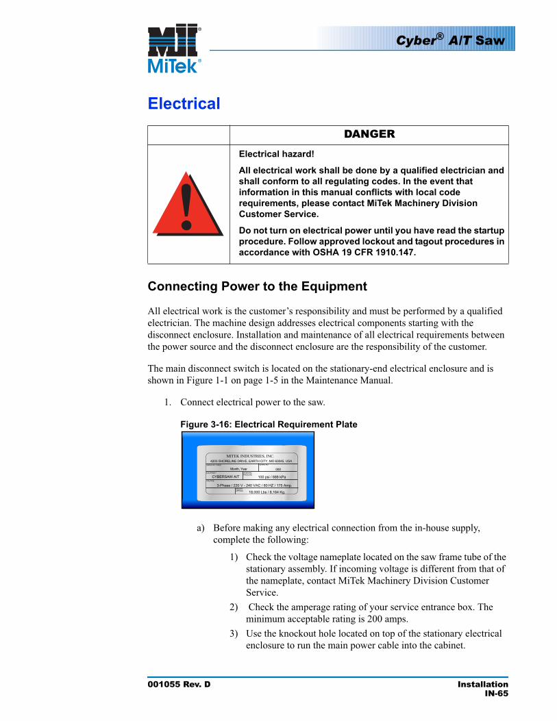
Cyber® A/T Saw
001055 Rev. D InstallationIN-65
Electrical
DANGER
Electrical hazard!
All electrical work shall be done by a qualified electrician and shall conform to all regulating codes. In the event that information in this manual conflicts with local code requirements, please contact MiTek Machinery Division Customer Service.
Do not turn on electrical power until you have read the startup procedure. Follow approved lockout and tagout procedures in accordance with OSHA 19 CFR 1910.147.
Connecting Power to the Equipment
All electrical work is the customer’s responsibility and must be performed by a qualified electrician. The machine design addresses electrical components starting with the disconnect enclosure. Installation and maintenance of all electrical requirements between the power source and the disconnect enclosure are the responsibility of the customer.
The main disconnect switch is located on the stationary-end electrical enclosure and is shown in Figure 1-1 on page 1-5 in the Maintenance Manual.
1. Connect electrical power to the saw.
Figure 3-16: Electrical Requirement Plate
a) Before making any electrical connection from the in-house supply, complete the following:
1) Check the voltage nameplate located on the saw frame tube of the stationary assembly. If incoming voltage is different from that of the nameplate, contact MiTek Machinery Division Customer Service.
2) Check the amperage rating of your service entrance box. The minimum acceptable rating is 200 amps.
3) Use the knockout hole located on top of the stationary electrical enclosure to run the main power cable into the cabinet.
!
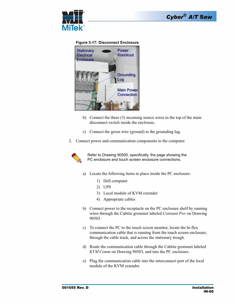
Cyber® A/T Saw
001055 Rev. D InstallationIN-66
Figure 3-17: Disconnect Enclosure
b) Connect the three (3) incoming source wires to the top of the main disconnect switch inside the enclosure.
c) Connect the green wire (ground) to the grounding lug.
2. Connect power and communication components to the computer.
Refer to Drawing 90500, specifically, the page showing the PC enclosure and touch screen enclosure connections.
a) Locate the following items to place inside the PC enclosure:
1) Dell computer2) UPS3) Local module of KVM extender4) Appropriate cables
b) Connect power to the receptacle on the PC enclosure shelf by running wires through the Cabtite grommet labeled Constant Pwr on Drawing 90503.
c) To connect the PC to the touch screen monitor, locate the hi-flex communication cable that is running from the touch screen enclosure, through the cable track, and across the stationary trough.
d) Route the communication cable through the Cabtite grommet labeled KVM Comm on Drawing 90503, and into the PC enclosure.
e) Plug the communication cable into the interconnect port of the local module of the KVM extender.
Cyber® A/T Saw
001055 Rev. D InstallationIN-67
f) Connect the KVM-supplied video cable to the local KVM extender. There are four (4) connectors to connect on the video cable.
1) The 25-pin sub-D connector on one end connects to the local KVM extender serial connection.
2) The three (3) connectors on the opposite end connect to the PC. There is a 25-pin sub-D connector that connects to the PC monitor port. The keyboard and a mouse PS-2 connector come off that cable and connect into their own ports.
g) Connect the KVM supplied serial cable to the local KVM extender serial connection on one end. Connect the other end of the serial cable to the serial connection on the PC.
h) Connect the 3.5-in. floppy drive to the PC. The USB connection from the floppy drive connects to a USB extension cable. Connect the extension cable to the USB port on the PC.
i) Connect the plant network cable to the PC at the network card. The port is labeled Plant Net on Drawing 90500. It runs through the Cabtite frame grommet, shown on Drawing 90503, and out to an in-line coupler. This coupler allows the plant network cable from the plant to connect right to the PC.
j) Connect the CAT 5 PLC network cable to the network connection on the PC. It is labeled PLC Net on Drawing 90500.
k) Route the PLC network cable through its grommet in the Cabtite connector. It is labeled PLC Network on Drawing 90503.
l) Connect the other end of the PLC network cable to the covered RJ-45 interface on the side of the stationary enclosure. This is where the plant network cable was formerly connected.
m) Plug a standard phone line into the second port on the side of the stationary enclosure, with the other end plugged into a phone jack. This line allows MiTek to connect to the saw for troubleshooting and upgrade purposes.
n) Place the UPS in the PC enclosure beside the PC.
o) Plug the UPS into the receptacle on the shelf above, running the cord from the UPS, behind the shelf, and into the receptacle.
p) Plug the PC power supply cord into the UPS.
q) Plug the enclosure cooling fan into the UPS.
Cyber® A/T Saw
001055 Rev. D InstallationIN-68
3. Adhere a touch screen overlay to the touch screen monitor.
CAUTIONKeep an overlay on your touch screen at all times!
It protects the touch pad, bezel, and touch screen from excessive wear, scratching, and other damage. It will greatly increase the life of your touch screen and help to maintain the quality of the on-screen image.
Inker and/or Catcher Display Options
If the Inker option is installed, the inker cable from the Inker must be connected to the lower comm port on the dual ethernet card on the PC. It is shown on Drawing 90500. The wiring is explained in the Inker Operation and Maintenance Manual. Drawing 90503 shows the grommet to use for the Inker.
If the Catcher Display option is installed, the Catcher Display cable from the Catcher Display must be connected to the upper comm port on the dual ethernet card. Drawing 90503 shows the grommets to use for the Catcher Display wires. The wiring is explained in the Catcher Display Installation Manual.
Computer Warranty
Computer
After the saw is installed and running, MiTek Machinery Division Customer Service transfers the warranty and registration for the Dell computer out of MiTek’s name. The computer is then registered to an individual name that must be determined during installation. At this time, the company owning the saw also owns the operating software license and the warranty to the computer. Dell will send an informational letter explaining their warranty policy. It is recommended that you keep this letter with the Cyber A/T saw manual. Refer to the Getting Technical Assistance and Warranty Information section on page 1-79 for more information.
Touch Screen
For technical assistance with the touch screen monitor or older models of the touch screen computer, contact MiTek.
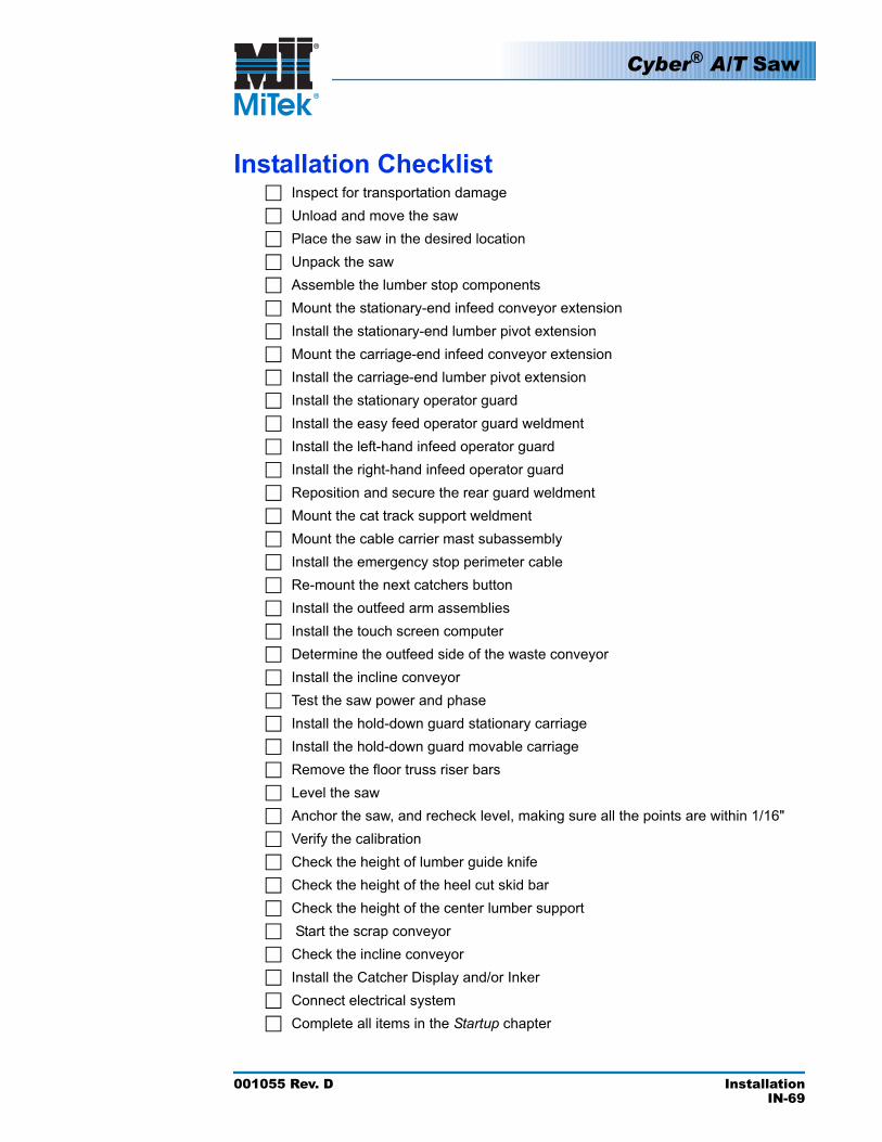
Cyber® A/T Saw
001055 Rev. D InstallationIN-69
Installation ChecklistInspect for transportation damageUnload and move the sawPlace the saw in the desired locationUnpack the sawAssemble the lumber stop componentsMount the stationary-end infeed conveyor extensionInstall the stationary-end lumber pivot extensionMount the carriage-end infeed conveyor extensionInstall the carriage-end lumber pivot extensionInstall the stationary operator guardInstall the easy feed operator guard weldmentInstall the left-hand infeed operator guardInstall the right-hand infeed operator guardReposition and secure the rear guard weldmentMount the cat track support weldmentMount the cable carrier mast subassemblyInstall the emergency stop perimeter cableRe-mount the next catchers buttonInstall the outfeed arm assembliesInstall the touch screen computerDetermine the outfeed side of the waste conveyorInstall the incline conveyorTest the saw power and phaseInstall the hold-down guard stationary carriageInstall the hold-down guard movable carriageRemove the floor truss riser barsLevel the sawAnchor the saw, and recheck level, making sure all the points are within 1/16"Verify the calibrationCheck the height of lumber guide knifeCheck the height of the heel cut skid barCheck the height of the center lumber support Start the scrap conveyorCheck the incline conveyorInstall the Catcher Display and/or InkerConnect electrical systemComplete all items in the Startup chapter

001055 Rev. D StartupIN-70
Preparing the Electrical System1. Turn on power to the saw. See the Turning On the Saw section on page OP-53 for detailed
startup instructions.
2. Turn on the computer. See the Turning On the Computer and Monitor section on page OP-53 for detailed startup instructions.
3. Press MANUAL to enter Manual Mode.
4. Check to make sure everyone is clear of the saw and nothing is in the way of moving the hold-downs up and down.
5. Check the five (5) E-stop red mushroom buttons on the saw by pressing each one and verifying it with the computer.
The saw will not start when any E-stop is activated or when the air supply is disconnected. The EMERGENCY SWITCHENGAGED light indicates this condition.
6. Check the emergency perimeter stop switch by pulling the cable. First, push the reset button on the switch to deactivate the alarm.
Figure 4-1: Emergency Perimeter Stop Switch
7. Press the carriage-end hold-down UP button to raise the hold-down.
8. If the hold-down moved down when you pressed the UP button, L1 and L3 of the incoming power to the saw must be swapped in order to reverse the direction of the motor. This should be performed only by a qualified electrician. Shut down the saw and disconnect the main power following approved lockout and tagout procedures.
Startup
This chapter describes the procedures required before operating your equipment.
Chapter 4
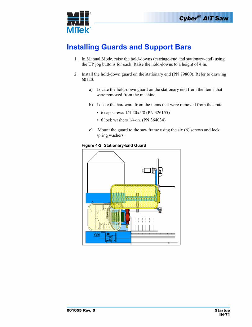
Cyber® A/T Saw
001055 Rev. D StartupIN-71
Installing Guards and Support Bars1. In Manual Mode, raise the hold-downs (carriage-end and stationary-end) using
the UP jog buttons for each. Raise the hold-downs to a height of 4 in.
2. Install the hold-down guard on the stationary end (PN 79800). Refer to drawing 60120.
a) Locate the hold-down guard on the stationary end from the items that were removed from the machine.
b) Locate the hardware from the items that were removed from the crate:
• 6 cap screws 1/4-20x5/8 (PN 326155)• 6 lock washers 1/4-in. (PN 364034)
c) Mount the guard to the saw frame using the six (6) screws and lock spring washers.
Figure 4-2: Stationary-End Guard
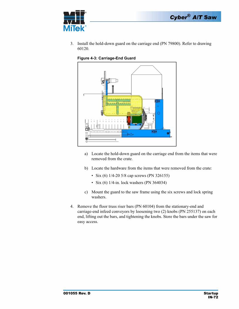
Cyber® A/T Saw
001055 Rev. D StartupIN-72
3. Install the hold-down guard on the carriage end (PN 79800). Refer to drawing 60120.
Figure 4-3: Carriage-End Guard
a) Locate the hold-down guard on the carriage end from the items that were removed from the crate.
b) Locate the hardware from the items that were removed from the crate:
• Six (6) 1/4-20 5/8 cap screws (PN 326155)• Six (6) 1/4-in. lock washers (PN 364034)
c) Mount the guard to the saw frame using the six screws and lock spring washers.
4. Remove the floor truss riser bars (PN 60104) from the stationary-end and carriage-end infeed conveyors by loosening two (2) knobs (PN 255137) on each end, lifting out the bars, and tightening the knobs. Store the bars under the saw for easy access.
Cyber® A/T Saw
001055 Rev. D StartupIN-73
Leveling and Anchoring
Failure to properly level and anchor the saw can result in inaccurate cuts. Saws installed on new concrete pads should be checked every six (6) months for two (2) years after installation to make sure settling of the concrete has not moved the saw out of level.
1. Level the saw.
a) Position the saw carriage between the third and fourth legs of the saw frame.
b) Press the operator panel emergency stop push button.
c) Set up a transit approximately 15 ft from the operator’s side of the saw. Choose a location for the transit so that above each saw frame leg, the angles that the carriage rides on are visible. Follow the manufacturer’s instructions when setting up the transit.
d) Adjust the leveling pads (PN 162100) so that there is approximately 2 in. between the bottom of the saw frame leg and the top of the leveling pad. Make sure the anchoring hole in the leveling pad is away from the saw.
e) Using the transit, position the transit rod over each leg on both sides of the saw, one at a time, and record the measurement.
f) Working on both sides of the saw, from one end to the other, adjust the leveling pads until all transit readings above the legs are within 1/16 in. of one another. Note: After adjusting a leveling pad, go back and check the leveling pads you have already adjusted and make any readjustments necessary.
2. Anchor the saw. Using the through hole in the leveling pads as a guide, drill a 1/2-in. diameter hole into the concrete a minimum of 5 in. deep.
CAUTIONThe saw MUST be anchored to the floor.
The vibration of the saw could cause it to travel, which may cause injury to personnel and affect the accuracy of the settings.
a) Use a shop vacuum to remove all concrete dust from the hole.
b) Anchor bolts (PN 305057) are provided with a flat washer and hex head nut. Thread an additional hex head nut half way onto the threaded portion of the anchor bolt. Run the hex head nut provided with the anchor bolt up to the hex head nut added to the bolt. This will prevent damaging the anchor bolt threads when driving in the anchor bolt.
c) Insert the anchor bolt through the leveling pad through hole and hole drilled into the concrete.
!
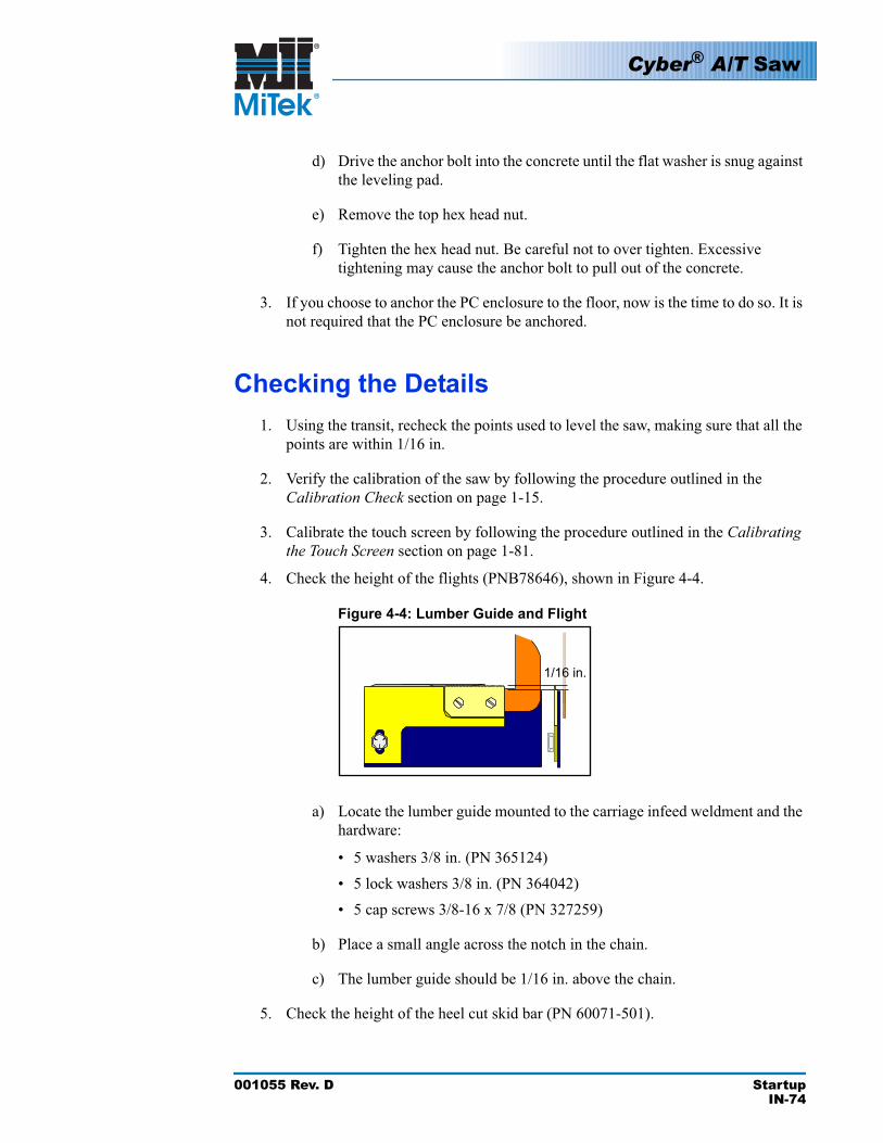
Cyber® A/T Saw
001055 Rev. D StartupIN-74
d) Drive the anchor bolt into the concrete until the flat washer is snug against the leveling pad.
e) Remove the top hex head nut.
f) Tighten the hex head nut. Be careful not to over tighten. Excessive tightening may cause the anchor bolt to pull out of the concrete.
3. If you choose to anchor the PC enclosure to the floor, now is the time to do so. It is not required that the PC enclosure be anchored.
Checking the Details1. Using the transit, recheck the points used to level the saw, making sure that all the
points are within 1/16 in.
2. Verify the calibration of the saw by following the procedure outlined in the Calibration Check section on page 1-15.
3. Calibrate the touch screen by following the procedure outlined in the Calibratingthe Touch Screen section on page 1-81.
4. Check the height of the flights (PNB78646), shown in Figure 4-4.
Figure 4-4: Lumber Guide and Flight
1/16 in.
a) Locate the lumber guide mounted to the carriage infeed weldment and the hardware:
• 5 washers 3/8 in. (PN 365124)• 5 lock washers 3/8 in. (PN 364042)• 5 cap screws 3/8-16 x 7/8 (PN 327259)
b) Place a small angle across the notch in the chain.
c) The lumber guide should be 1/16 in. above the chain.
5. Check the height of the heel cut skid bar (PN 60071-501).
Cyber® A/T Saw
001055 Rev. D StartupIN-75
a) Place the saw in Semiautomatic Mode by pressing the SEMI-AUTO button on the touch screen’s Main Menu.
b) Enter 90° for all blade angles.
c) Place the skid bar across the machine.
d) Place a board on the conveyor so that it will not touch the blades as it passes them.
e) Press the INITIATE SETUP button.
f) Using the infeed conveyor FORWARD jog button, move the board in front of blade 3.
g) Adjust the infeed side of the heel cut skid bar so that it touches the board.
h) Using the FORWARD jog button, move the board in front of the blade 5 and/or blade 6.
i) Adjust the outfeed side of the skid bar until it touches the board.
j) Using the REVERSE jog button move the board back in front of blade 2 and/or blade 3. Recheck the front side and make any fine adjustments as necessary.
6. Check the height of the center lumber support (PN 77494).
a) Place the saw in Semiautomatic Mode by pressing the SEMI-AUTO button on the touch screen’s Main Menu.
b) Enter 90° for all blade angles.
c) Place the center lumber support skid bar across the machine, centered between the infeed conveyors.
d) Place a board on the conveyor so that it will not touch the blades as it passes them.
e) Press the INITIATE SETUP button.
f) Use the infeed conveyor FORWARD jog button to move the board in front of blade 3.
g) Adjust the infeed side of the center lumber support so that it touches the board.
h) Using the FORWARD jog button, move the board in front of blade 5 and/or blade 6.
Cyber® A/T Saw
001055 Rev. D StartupIN-76
i) Adjust the outfeed side of the center lumber support until it touches the board.
j) Using the REVERSE jog button, move the board back in front of blade 2 and/or blade 3. Recheck the front side and make any fine adjustments as necessary.
7. Start the waste conveyor by pressing the WASTE CONV. START button.
a) If the motor was moved, the direction of the conveyor direction may need to be reversed.
1) Turn all electric power to the saw OFF at the main in-house electrical panel to the saw.
2) Turn the saw disconnect switch, located on the primary (large) electrical panel at the stationary end of the saw, to the OFF position.
3) Remove the front cover from the electrical junction box on the side of the incline conveyor.
4) Reverse any two black wires in the junction box.5) Put the connector cap back on the wires and replace the junction
box cover.6) Turn both electrical power switches ON.7) The belt direction should now be correct.
b) Check the alignment of the belt. (If the belt does not track straight and in the center of the pan. See the Adjusting the Belt Tracking/Tension section on page 1-67.
8. Check the incline conveyor.
a) Start the incline conveyor by pressing the INC CONV. START button.
b) Check the direction of the belt. If the belt is running in the wrong direction, it can be changed as follows:
1) Turn all electric power to the saw OFF at the main in-house electrical panel to the saw. Follow all lockout and tagout procedures.
2) Turn the saw disconnect switch located on the primary (large) electrical panel at the stationary end of the saw, to the OFF position.
3) Remove the front cover from the electrical junction box on the side of the incline conveyor.
4) Reverse any two black wires in the junction box.5) Put connector cap back on the wires and replace junction box
cover.
Cyber® A/T Saw
001055 Rev. D StartupIN-77
6) Turn both electrical power switches ON.7) Belt direction should now be correct.
c) Check the alignment of the belt. If the belt does not track straight and in the center of the pan, refer to the Adjusting the Belt Tracking/Tensionsection on page 1-67.
The operational tests should be performed before the machine is put into production. You will need to verify the calibration of the saw. See the Calibration Check section on page 1-15.
Checking Motor Rotation
DANGER
9. If the motor rotation is incorrect:
a) Reverse any two wires at the motor.
b) Check the direction again.
Safety TestsPerform the safety tests described on page SAFETY-12 before operating the saw. See page page SAFETY-28 for the safety test translated to Spanish.
WARNINGELECTROCUTION, HIGH PRESSURE, CRUSH, CUT, AND CHEMICAL HAZARDS!
Do not attempt to start the system without a MiTek representative present!
Serious injury and/or equipment damage may result.
!
001055 Rev. D IndexIN-78
Aair pressure, minimum 41anchoring saw 73
Bblades
checking 13brakes
inspecting 13test 14
Ccable
bundle 55carrier mast 55
carriagehold-down guard 72infeed conveyor extension 50lumber pivot extension 51operator guard 51
cat track support weldment 54Catcher Display 54, 68caution logo 2center lumber support 75chains, conveyor extension 49communications, computer 66compressed air, see pneumatic systemcomputer
communications components 66installation 58warranty 68
conveyoradjusting 62incline 64, 76infeed 49, 50waste 62, 76
Customer Service 34customer-supplied parts
electrical 42pneumatic system 42
tools 42transport equipment 42
Ddanger logos 2delivery 44disconnect
enclosure 66switch 65
drawing set, part number 33
Eelectrical
connecting power 65customer-supplied parts 42disconnect enclosure 65enclosures 39installation 65PC enclosure 40preparing 70requirements 36, 39startup 70
enclosuredisconnect 66PC 66
environment 39environmental logo 2equipment, transport 42E-stop
perimeter safety cable 55, 70testing 12
Ffilter 41filter-regulator-lubricator (FRL) assembly 41floor structure 39floor truss web riser bars 72
Index

001055 Rev. D IndexIN-79
Gguard 51
stationary operator 51guards
checking 14Easyfeed operator weldment 51hold-down 72infeed operator 52installation 71lumber stop 47operator 51rear weldment 53tube weldment 51
Hhazard indicator 2heel cut skid bar 74
Iincline conveyor 64, 76infeed conveyor 49, 50Inker 68installation
anchoring saw 73checklist 69computer 58customer responsibilities 43delivery 44electrical 65guards 71leveling saw 56manual 33moving saw 45saw 47touch screen 58
KKVM extender 61
Llayout, sample 38lifting saw 45location requirements 39lockout/tagout
guidelines 5procedure 6, 8, 21, 23
lubricator 41lumber
center support 75guide 74pivot extension 50
lumber stop 47guard 47motor assembly 48pointer 48
Mmaintenance
Manual 33space required 36, 37
manualhow to use 33introduction 31navigation 32purpose 31understanding formatting 33
MiTek’s responsibilitiesduring installation 35prior to installation 35
motorschecking rotation 77conveyor drive 62lumber stop assembly 48
moving saw 45
Index

001055 Rev. D IndexIN-80
Nnotice logo 2notice of change iii
Ooperation
incline conveyor 76Manual 33space required 37waste conveyor 76
operator guard 51options 68outfeed arm assembly 56
Ppage change iiipatents iiperimeter safety cable 55, 70PLC 67pneumatic system
customer-supplied parts 42filter 41FRL assembly 41lubricator 41regulator 41requirements 41system pressure 41
prior to installationcustomer-supplied parts 42overview 36requirements
electrical 39location 39pneumatic system 41
pull-cord 55, 70
Rregulator 41regulator filter 41restricted zones 10, 26return goods ii
Ssafety
lockout/tagout 5, 32restricted zones 10, 26safety indicators 2safety rules 2, 16tests 12
sample layout 38scrap conveyor, see waste conveyorshipping information 42space
for equipment 37for maintenance 37for operation 37
startupchecking 74
stationary operator guard 51
Ttake-away conveyor, see waste conveyortouch screen
installation 58warranty 68
training 42transport equipment 42
UUPS (uninterruptible power supply) 60
Index
001055 Rev. D IndexIN-81
Wwarning logo 2warranty
computer 68touch screen 68
waste conveyor 62, 76
Index
Cyb
er A
/T
Cyb
er A
/T
Cyb
er A
/T
Com
ponent Cutting Saw
Operation M
anual
Com
ponent Cutting Saw
Maintenance M
anual
Com
ponent Cutting Saw
Installation Manual
001055Rev. D1 of 3
001055Rev. D2 of 3
001055Rev. D3 of 3
® ®
®