cvs v-100 ball valves 2 through 12 inch designs.cvs-controls.com/literature/cvs v-100 ball valve...
TRANSCRIPT

Product Manual
CVS V-100 Ball Valves 2 through 12 Inch Designs. Introduction: These instructions apply specifically to the 2 through 12 inch CVS V-100 Ball Valve Bodies. This manual provides maintenance, operation, installation, and parts ordering information. The valve bodies are normally equipped with actuators and accessories. Please refer to the appropriate instruction manuals. Excellent Pressure and Flow Control for steam, gasses, various liquid, and fibrous slurries. The CVS V-100 ball valve design utilizes a standard ball with a triangular shaped wedge formed in it. This design allows for both throttling control and on/off service used in conjunction with a variety of actuators. The CVS V-100 valve design closes against one of several available ball seals with a shearing action. The CVS V-100 is a flangeless design and allows the valve body to fit between two existing pipeline flanges. The flow characteristic is modified equal percent, with normal (forward) flow into the convex side of the V-ball. Bi-directional flow is into either side of the V-Ball; TCM ball seal, metal ball seal, or flow ring. Typical actuators used; are the pneumatic spring and diaphragm rotary actuator (CVS 1051), and the pneumatic piston rotary actuator (CVS 1061). Mounting of these actuators can be on the right-hand or left-hand side viewed from the forward flow inlet. Sour Service Capability, optional NACE MRO175/ISO 15156-2009 Refer to page 2 for additional specifications.
Installation: The valve body and internal components are made of specific materials, and are designed for specific temperature, fluid control, pressure, and pressure drop conditions. The following listed parts may compromise the valve if temperature ranges and service drops have been exceeded; Body, bushings, shaft, and ball seals. Operation of these valves outside the specified application ranges may cause damage to equipment and or personal injury. These valves must not be used outside the specified condition ranges without contacting your CVS sales representative. CVS recommends the installation of pressure control or pressure relieving devices.
Design CVS V-100 Valve Body Shown with CVS Type 1051 Actuator
CVS Controls Ltd. Process Management and Instrumentation
CVS Controls Ltd Product Manual: CVS V-100 Ball Valve
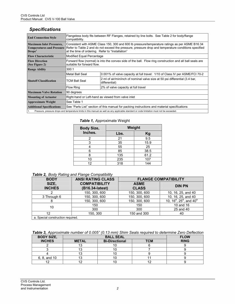
Specifications
End Connection Style Flangeless body fits between RF Flanges, retained by line bolts. See Table 2 for body/flange compatibility.
Maximum Inlet Pressures, Temperatures and Pressure Drops1
Consistent with ASME Class 150, 300 and 600 lb pressure/temperature ratings as per ASME B16.34 Refer to Table 2 and do not exceed the pressure, pressure drop and temperature conditions specified at the time of ordering. Refer to “Installation”
Flow Characteristic Modified Equal Percentage Flow Direction (See Figure 2)
Forward flow (normal) is into the convex side of the ball. Flow ring construction and all ball seals are suitable for forward flow.
Range Ability 300:1
Shutoff Classification
Metal Ball Seal 0.001% of valve capacity at full travel: 1/10 of Class IV per ASME/FCI 70-2
TCM Ball Seal 2 ml of air/min/inch of nominal valve size at 50 psi differential (3.4 bar, differential)
Flow Ring 2% of valve capacity at full travel Maximum Valve Rotation 90 degrees Mounting of Actuator Right-hand or Left-hand as viewed from valve inlet Approximate Weight See Table 1 Additional Specifications See “Parts List” section of this manual for packing instructions and material specifications 1. Pressure, pressure drops and temperature limits in this manual as well as any applicable standard or code limitation must not be exceeded.
Table 1, Approximate Weight
Table 2, Body Rating and Flange Compatibility BODY SIZE,
INCHES
ANSI RATING CLASS COMPATIBILITY (B16.34-latest)
FLANGE COMPATIBILITY ASME CLASS DIN PN
2 150, 300, 600 150, 300, 600 10, 16, 25, and 40 3 Through 6 150, 300, 600 150, 300, 600 10, 16, 25, and 40
8 150, 300, 600 150, 300, 600 10, 16a, 25a, and 40a
10 150 150 10 and 16 300 300 25 and 40
12 150, 300 150 and 300 40 a. Special construction required.
Table 3, Approximate number of 0.005” (0.13 mm) Shim Seals required to determine Zero Deflection BODY SIZE,
INCHES BALL SEAL FLOW
RING METAL Bi-Directional TCM 2 13 10 6 9 3 13 10 7 9 4 13 10 9 9
6, 8, and 10 13 10 11 9 12 12 10 12 9
Body Size, Inches.
Weight Lbs. Kg
2 21 9.5 3 35 15.9 4 55 25 6 85 38.5 8 135 61.2 10 235 107 12 318 144
CVS Controls Ltd. Process Management and Instrumentation 2

CVS Controls Ltd Product Manual: CVS V-100 Ball Valve
Table 4, Number of 0.005 (0.13 mm) thick Shim Seals to Remove after Determining Zero Deflection
BODY SIZE, INCHES
BALL SEAL METAL Bi-Directional TCM
2 4 3 1 3 4 4 2 4 4 4 4
6, 8, and 10 4 4 6 12 4 4 7
Table 5, Min. Clearance for Flow Ring Construction
SERVICE TEMPERATURE
FORWARD FLOW
REVERSE FLOW
°F °C In. mm In. mm To 405 To 207 0.015 0.38 0.030 0.76
Above 405 Above 207 0.025 0.64 0.040 1.02 Table 6, Recommended Bolt Torque
KEY NUMBER BODY SIZE, INCHES
BOLT TORQUE ft●lb. N●m
Guide Post Retainer Nut
Key 6
2 27 37 3 43 58 4 65 88 6 95 129
8 and 10 200 271 12 95 129
Cap Screw Key 11
2-6 65 88 8 through 12 100 136
Installation: Inspect the valves for shipping damage and foreign debris when uncrating. CVS recommends the installation of a standard three-valve maintenance by-pass system. This allows for isolation of the valve body without shutting down the pipeline. 1. Ensure the pipeline is free of welding slag,
and foreign debris by blowing out the pipe lines before installation.
2. When mounting between pipeline flanges, ensure the two connecting flanges are in line. Install approved gaskets between the valve body and the pipeline flanges.
3. Position the valve on the line so that the flow direction indicator corresponds to the direction of the flow of the pipeline. If the valve body is being used in a bi-directional flow application then the flow direction indicator should correspond to the direction of the highest flow condition.
4. When installing flange bolts, use figure No 4 to obtain necessary clearances.
5. Tighten the bolts in a crisscross pastern to ensure all bolts are evenly torqued.
6. Install the CVS V-100 ball valve horizontally in the pipeline with the ball valve closing downward. The actuator can be installed in a number of positions; refer to figure 3 and the actuator instruction manual.
CVS Controls Ltd. Process Management
3 and Instrumentation
CVS Controls Ltd Product Manual: CVS V-100 Ball Valve
Installation Cont.: 7. When a manual actuator is used in
combination with a power actuator, it will be necessary to install a bypass valve on the power actuator. This will allow the operation of the manual actuator. Following the power actuator instruction, connect he pressure line to the actuator.
Note: Grounding the valve shaft is required when the valve is exposed to hazardous goods or installed for oxygen use. Without grounding the valve shaft, an explosive situation may result from the static electricity from the valve parts. Maintenance: Scheduled inspections and maintenance are vital to continued operation of all pressure control valves and systems. Parts are subject to wear and tear and must be replaced as necessary, depending on the intensity of service conditions.
Warning:
To avoid personal injury or damage to the process system, disconnect operating lines providing air pressure, control signals or electrical power to the actuator. Ensure the actuator cannot suddenly open or close.
Isolate the valve from the system by using by-pass valves or by shutting off the process entirely. Relieve any pressure contained on both sides of the valve and drain the process media. Vent the power actuator, relieve actuator spring pressure and use proper lock-out methods during all maintenance procedures.
Replacing Packing: When conducting packing maintenance, the actuator must be removed from the valve. It is also recommended that the valve be removed from the pipeline to allow for adjustment of the valve closed position. If the packing is new and tight on the shaft, and if leakage cannot be stopped by tightening the packing nuts, it is likely that the shaft has become worn or nicked. If the leakage originates from the outside diameter of the packing, nicks or scratches may have damaged the packing box wall. Inspect the shaft and packing box during the following procedures. If it is not possible to control leakage around the valve shaft by tightening packing flange bolts, the packing may need to be replaced. Split-Ring Packing: Before beginning any maintenance, it is important to isolate the control valve and release all pressure contained in the valve body and the actuator. Note: exercise caution during disassembly. Nicks and scratches will affect the ability to seal the valve in the future. 1. Remove packing flange nuts (key 3) and lift
the packing follower (key 15) from the packing box.
2. With a formed wire hook remove the packing rings.
3. Clean the packing box, all metal parts, and complete the required maintenance.
4. Expand the split ring of the new packing to allow it to pass over the valve shaft. Stager the connecting lines, then slide the rings in to the packing box.
5. Tighten the packing flange nuts until they are finger tight. Test under flow conditions. Continue tightening the nuts until all leakage has stopped.
CVS Controls Ltd. Process Management and Instrumentation 4

CVS Controls Ltd Product Manual: CVS V-100 Ball Valve
Solid Ring Packing: Isolate the control valve. Release all pressure contained in the valve body, and the actuator. Prior to disassembly, note the orientation of the actuator and lever in relation to the valve body.
Use caution when removing the actuator lever, using a wheel-puller if necessary. If the actuator lever is forced off the valve shaft the ball could move from the centered position,damaging the V-Ball, seal and valve body.
1. Remove the actuator cover. 2. Remove the lever. 3. Disconnect the actuator and body cap screws
(key 4) and hex nut if used (key 5) 4. Remove the packing flange nuts (key 3),
packing flange, if used, and packing follower. 5. Remove the packing rings (key 6) with a
formed wire hook. To remove the TFE V-ring packing, the wire hook should have a sharp end to allow you to pierce the packing for removal.
6. Clean the packing box, all metal parts and complete all required maintenance.
7. Replacing single packing 7.1 Replace the packing box ring
(key 18). 7.2 Next, replace the packing rings
(key 6). 8. Replacing double packing arrangements
8.1 Replace the packing box ring (key 18).
8.2 Replace one half of the total number of packing rings (key 6).
8.3 Install the packing washer, if used. 8.4 Replace the lantern ring and the
remaining packing rings. 8.5 If used, replace the packing 8.6 Install the packing follower (key
15) 8.7 Replace the packing flange, if
used 8.8 Replace and tighten the packing
flange nuts until they are finger tight.
9. Reconnect the actuator following the previously noted orientation.
10. Replace the cap screws (key 4) and hex nuts (key 5) using the torques from table 6.
11. Follow the actuator instruction manual to complete the actuator assembly and to set the travel adjustment.
12. After the valve is placed in service, the packing flange nuts may require retightening to prevent leakage.
Ball Seal or Flow Ring Maintenance: Caution must be used when working near the V-ball. The V-Ball closes with a shearing, cutting motion and can cause personal injury or property damage if objects become caught in a closing valve. Be sure to keep the path of the V-notch valve clear while stroking the valve. Disassembly: 1. Isolate the valve from the line.
1.1 It is necessary for the removed valve to be positioned so that the seal ring or flow ring is pointed upward
1.2 Ensure that V-ball (key 21) is in the open position.
2. Remove the cap screws that secure the seal protector ring in place.
3. Carefully remove the ring from the body, ensuring that the surface of the ball is not nicked or scraped.
4. Remove the O-ring (key 24), if used.
Figure 1. Section view of Heavy Duty Composition (TCM) Ball Seal
CVS Controls Ltd. Process Management
5 and Instrumentation
CVS Controls Ltd Product Manual: CVS V-100 Ball Valve Ball Seal or Flow Ring Maintenance Cont’d: 5. Mark the position of the ball seal and the
valve body, so that it can be returned to its original position when it is reinstalled.
6. Carefully remove: 6.1 The bi-directional metal or TCM ball seal
(key 23) 6.2 The back-up ring 6.3 Shim seals
7. Clean all parts and inspect for damage. Installation of Metal, Bi-directional Metal or Heavy-Duty Composition (TCM) Ball Seal. 1. Inspect the sealing surface of the valve body
for nicks and scratches that will prevent the shims from sealing.
2. Turn the V-ball to the closed position and install the appropriate number of shims
(Key 20) from table 3. For the bi-directional metal ball seal, use a 1/1000-inch or 1/4 mm thick test shim. A piece of paper would be a suitable alternative. Place the test shim across the ball face.
3. Check for nicks and scratches on the ball seal, sealing surface, and backup ring. Install the ball seal and the backup ring on top of the shim seals. If damage was detected on any of the components, the damage should be turned away from the V-ball. Install the bi-directional ball seals, to ensure proper orientation, use the marks made in step number 5 of the removal.
4. Metal and TCM ball seals: 4.1 Install seal protector ring (key 22) on the
ball seal and shim seals (key 23 and key 20).
4.2 Secure the seal protector ring and the ball seal to the valve body by threading and tightening the capscrews. To obtain the closest ball deflection to zero, add and remove shim seals (key 20).
4.3 Zero ball seal deflection is when a .005
inch or 0.13 mm shim causes the seal to be broken between the v-notched ball and the ball seal. The parts must be secure or an inaccurate zero will result.
5. Bi directional metal ball seals: 5.1 Install seal protector ring (key 22) on the
ball seal and shim seals (key 24 and key 20).
5.2 Secure the seal protector ring, ball seal and shims (key 24 and 20) by threading and tightening the capscrews (key 19).
5.3 Zero ball seal deflection can be tested by removing the 1/1000 of an inch or .025 mm thick test shim from under the ball seal. If this is possible, remove the seal protector ring, the ball seal, and the back-up ring.
5.4 To check the zero deflection, remove one shim, and assemble the parts. Attempt to remove one 1/1000 inch or 0.025mm shim. If the shim is neither to tight or to loose, then zero deflection is obtained.
6. Once zero deflection is obtained remove: 6.1 The seal protector ring 6.2 The ball seal 6.3 The back up ring (if the bi-directional
metal seal is used) 6.4 The number of seals indicated in table 4. 6.5 For the bi-directional metal ball seal leave
at least one shim seal in the body. 7. Install the ball seal and the backup ring, if one
is used. 8. For metal ball seals, install one shim seal (key
20) on top of the metal ball seal. 9. Install 0-ring (key 24), if used, into the body. 10. Ensure that the ball seal is centered on the V-
ball. For the bi-directional ball match orientation marks that were made in step 5 of the removal section.
11. Install the seal protector ring (key 22) and screw the cap screws and washers, (if used) to secure the body.
CVS Controls Ltd. Process Management and Instrumentation 6

CVS Controls Ltd Product Manual: CVS V-100 Ball Valve
Installation of Flow Ring: 1. Ensure that the V-ball (Key 21) is in the closed
position. Replace the shim seals in the body Table #3
2. Install the O-ring (Key 24) in the body and position the flow ring to ensure that it is centered and that it does not touch the v-ball.
3. Install the washers that hold the seal protector and twist on the cap screws.
4. Check the minimum clearance of the flow ring and the V-ball from table 5. Measure the existing clearance and adjust to obtain the minimum clearance by adding and removing shims.
Drive Shaft and V-Ball: Disassembly:
Caution: Use care when removing the actuator lever, using a wheel-puller if necessary. If the actuator lever is forced off the valve shaft the ball could move from the centered position, damaging the V-Ball, seal and valve body.
Before disassembly, note the orientation of the actuator in relation to the body and note the orientation of the lever in relation to the valve body. 1. Remove the actuator cover. 2. Remover the lever.
When the actuator is removed from the valve body, the ball/shaft assembly may rotate and cause personal injury or damage to equipment. Prevent rotation by turning the V-Ball to a stable position in the body.
3. Detach the valve from the line. It is
necessary for the removed valve to be positioned so that the seal ring or flow ring is pointed upward
4. Unscrew the cap screws (key 19) that hold the seal protector ring in place (key 22).
5. Carefully remove the ring from the body
ensuring that the surface of the ball is not nicked or scraped
6. Remove the O-ring (key 24). 7 Remove the ball seal (key 23) from the ball
seal constructions. 8. Lift the shim seals (key 20). 9. Clean all parts and inspect for damage. 10. Remove packing flange nuts (key 3) and lift
the packing flange and follower (key 15) from the packing box.
11. With a formed wire hook, remove the packing rings.
12. Clean the packing box and all metal parts complete all required maintenance.
13. Locate and remove the groove pin (key 10). 14. Unscrew the guidepost retaining nuts (key
14) or the retainer, depending on valve body size.
15. Support the V-ball securely and remove the guidepost, not allowing the guidepost to scratch the seal.
16. Remove: 16.1 Guide post retainer (key 25) 16.2 Guide post (key 13) 16.3 Gasket (key 12) 16.4 Spring retainer washer (for sizes 3
inch and larger). 17. The drive shaft is pushed into the body from
the bonnet. The drive shaft is aligned with the guidepost bushing. (key 11)
18 Find the groove pin hole, noting that the V-Ball has a raised flat surface on one side. To remove the groove pin, place a punch on the side of the ball opposite the raised flat surface and drive the out pin (Key 10). See Figure 12.
19. Slip the drive shaft through the body out the guidepost end. Remove the thrust washer.
20. Carefully remove the ball from the body ensuring that the surface of the ball is not nicked or scraped.
To remove the bearings (Keys 8 and 11) see figure 5 for replacing the bearings. Refer to the bearing replacement procedure. When a new body (Key 7) and drive shaft bearing (Key 8) or V-Ball (Key 21) and guide post bearing (Key 11) is ordered, the bearing will be pressed in at the factory.
CVS Controls Ltd. Process Management
7 and Instrumentation

CVS Controls Ltd Product Manual: CVS V-100 Ball Valve
Assembly: 1. Follow the instructions on the bushing
replacement from this manual. 2. Carefully insert the V-ball in the body
ensuring the surface of the ball is not nicked or scraped. Provide secure support for the V-ball.
While installing the drive shaft, hold the thrust washer(s) (Key9) between the drive shaft bearing (Key 8) and the V-Ball (Key 21).
3. Slip the drive shaft into the guidepost end through body.
4. Match the index mark on the shaft with index mark on the V-ball.
5. Gasket installation 5.1 2 In Body – Slip the gasket (key 12)
over the guide post (key 13) and hold the wave spring, if used, between the ball and the body. Insert the guidepost assembly into the body, wave spring, and ball valve.
5.3 3, thru 8 inch bodies - Slide both the gasket (key 12) and the spring retainer washer (if required) over the guide post (key 13) and hold the wave spring, if used, between the V-ball and the body. Insert the guidepost assembly into the body, wave spring, and ball valve.
6. Insert the retainer for the guidepost and secure with retainer nuts; for body sizes 2-through 8 inch. Tighten nuts to the recommended torque from table 6.
7. Insert groove pin (key 10) to lock the drive shaft and V-ball connection. The pin should enter from the large hole and go towards the smaller diameter hole. The pin should be flush with both ends.
8. Replace the packing box ring (key 18) and install the new packing (key 6).
9. Install the packing follower (key 15) and replace the packing flange if used. Replace and tighten the packing flange nuts until they are finger tight. When under actual flow conditions the nuts will need additional tightening to control leaking.
10. Following the instructions under ‘Ball Seal or
Flow Ring Maintenance”, replace the ball seal or flow ring.
11. Reconnect the actuator using the actuator orientation that was noted previously. The cap screws (key 4) and hex nuts (key 5) should be torqued to the values listed in table 6.
12. Install the lever using orientation that was noted previously and the identifying marks from figure 3.
13. Use the appropriate actuator instructions for remaining mounting instructions and the travel adjustment.
Bushing Replacement CVS does not recommend replacing bushings in the field. The procedure is difficult and may cause permanent damage to the V-ball. If replacement of the bushing in the field is necessary, follow the instructions that follow and the dimensions in figure 5.
Note: Do not heat the valve in an attempt to ease the replacement procedure of the body bushing. Heating the valve will cause the plastic-lined material to release fluorine gas, which is extremely hazardous, causing; poisoning, suffocation, and burns.
Taper Pinhole
Figure 2. V-Ball showing Groove Pin Hole
CVS Controls Ltd. Process Management and Instrumentation 8

CVS Controls Ltd Product Manual: CVS V-100 Ball Valve
MOUNTING STYLE 1 2 3 4
ACTUATOR POSITIONVALVE OPEN
ACTUATOR
RIGHT
LEFT
HANDED
HANDED
STYLE A
( PDTC )
STYLE B
( PDTO )
STYLE C
( PDTC )
STYLE D
( PDTO )
NOTES: 1. ARROW ON LEVER INDICATES DIRECTION OF ACTUATOR THRUST TO CLOSE VALVE. 2. PDTC-PUSH DOWN TO CLOSE; PDTO-PUSH DOWN TO OPEN 3. RIGHT-HAND MOUNTING CONTROLS WITH V NOTCH NO. 1 LEFT-HAND MOUNTING CONTROLS WITH V NOTCH NO. 2 4. FOR 60-DEG OPERATION WITH PUSH DOWN-TO-CLOSE ACTION
(EXTENDING ACTUATOR ROD CLOSES VALVE), ROTATE ACTUATOR LEVER CLOCKWISE SO THAT LEVER INDEX MARK IS OFFSET 1 SPLINE TOOTH FROM VALVE SHAFT INDEX MARK FOR 1/2" THROUGH 3/4" (12.7 mm THROUGH 19.1 mm) VALVE SHAFTS AND 2 SPLINETEETH FROM VALVE SHAFT INDEX MARK FOR 7/8" (22.2 mm) AND LARGER VALVE SHAFTS.
CONSTRUCTIONBODYSIZE,
INCHES
A BMM
ANSI FLANGES(1) (1)
CLASS 300CLASS 150 CLASS 600
mmIn. mmIn. In. mm In. mm In. mm
STANDARD
2
3
4
6
8
4.88
6.50
7.62
9.00
9.56
124
165
194
229
243
4.00
3.12
2.19
3.00
146
102
79
76
56
5.75
13.62
11.44
8.25
10.12
391
365
346
346
15.38
14.38
308
282
216
291
270
206
12.12
11.12
8.50
13.62
2359.25
17.12
16.50
13.62
11.50
435
419
346
292
1. DOES NOT INCLUDE GASKETS
Figure 3. Index Marks for Actuator Lever Orientation
Figure 4. Required clearances for installation of design CVS V-100 Ball Valve Body
C
28
Construction Body Size
Inches
A(1) B(1)
C
ASME Flanges
150 300 600 In. mm In. mm In. mm In. mm In. mm
Standard
2 4.88 124 2.19 56 8.25 206 8.50 216 9.25 235 3 6.50 165 3.00 76 10.12 270 11.12 282 11.50 292
4 7.62 194 3.12 79 11.44 290 12.12 308 13.62 346 6 9.00 229 4.00 102 13.62 346 14.38 365 16.50 419
8 9.56 243 5.75 146 13.62 346 15.38 391 17.12 435
10 11.70 297 6.28 160 16.75 425 19.38 492 -- 12 13.30 338 7.25 184 20.13 511 22.25 565 --
1.Does not include gaskets
CVS Controls Ltd. Process Management
9 and Instrumentation

CVS Controls Ltd Product Manual: CVS V-100 Ball Valve
BODY SIZE,
IN
BODY BUSHING GUIDE POST BUSHING
A B RAMS 1 & 2
C D E (min.) A B
RAMS 3 & 4
E (min.) RAM 1 RAM 2 RAM 3 RAM 4
mm In. mm In. mm In. mm In. mm In. mm In. mm In mm In. mm In. mm In
2 15.37 .060 25.40 1.000 12.70 .500 19.05 .750 80.84 3.183
114 4.5 19.81 .780
29.92 1.06 15.88 .625
25 1.0 15.11 .595 24.89 .980 12.45 .490 18.80 .740 80.79 3.181 19.56 .770 15.62 .615
3 21.72 .855 31.75 1.250 19.05 .750 26.44 1.041 117.17 4.613
146 5.75 29.46 1.160
36.51 1.44 23.75 .935
38 1.5 21.46 .845 31.24 1.230 18.80 .740 26.19 1.031 117.09 4.610 29.21 1.150 23.50 .925
4 24.89 .980 34.93 1.375 22.23 .875 29.59 1.165 141.81 5.583
152 6 32.51 1.280
39.69 1.56 26.92 1.060
38 1.5 24.64 .970 34.42 1.355 21.97 .865 29.34 1.155 141.73 5.580 32.26 1.270 26.67 1.050
6 28.07 1.105 41.28 1.625 1.000 1.000 34.37 1.353 190.12 7.485
165 6.5 37.34 1.470
44.45 1.75 31.75 1.250
51 2.0 27.81 1.095 48.77 1.605 .990 .990 34.11 1.343 190.02 7.481 37.08 1.460 31.50 1.240
8 34.42 1.355 49.23 1.938 31.75 1.250 40.72 1.603 233.86 9.207
191 7.5 43.69 1.720
50.8 2 38.10 1.500
51 2.0 34.16 1.345 48.72 1.918 31.50 1.240 40.46 1.593 233.76 9.203 43.43 1.710 37.85 1.490
10 34.42 1.355 49.23 1.938 31.75 1.250 40.72 1.603 287.50 11.319
191 7.5 43.69 1.720
50.8 2 38.10 1.500
51 2.0 34.16 1.345 48.72 1.918 31.50 1.240 40.46 1.593 287.38 11.314 43.43 1.710 37.85 1.490
12 40.77 1.605 53.96 2.125 38.10 1.500 45.54 1.793 345.39 13.598
216 8.5 48.39 1.905
55.56 2.19 42.82 1.686
51 2.0 40.51 1.595 53.47 2.105 37.85 1.490 45.29 1.783 345.26 13.593 48.13 1.895 42.57 1.676
NOTE:
Figure 5. Ram Dimensions for replacing Bearings CVS Controls Ltd. Process Management and Instrumentation 10

CVS Controls Ltd Product Manual: CVS V-100 Ball Valve
Body Bushings 1. Follow the instructions for disassembly in the
“Drive Shaft and V-Ball Disassembly” section of this manual.
2. From figure 5 select the proper size ram and insert it in the body. This will allow you to drive out the bushing with a hydraulic press.
3. Apply a suitable lubricant to the outside diameter of the bushing. CVS recommends the lubricant Moly-Kote.
4. To install the bushing: 4.1 Place the bushing in the bushing bore 4.2 Ensure that the bushing lead is in the
chamber is turned toward the bushing bore 4.3 2 thru 8 inch –drive the bushings into the
body using ram 2. The bushing is in the suitable position when larger shoulder on the ram contacts the valve body.
5. Follow the assembly instruction in the Drive shaft V-Ball section of this manual.
Guide Post Bushing 1 Follow the instruction for the removal of the V-
Ball in the “Drive Shaft and V-Ball disassembly” section of this manual.
2. Ensuring that the ball is properly supported, insert the proper ram size 1. Without proper support, the ball can be permanently damaged.
3. Remove the old bushing using a hydraulic press. 4. Apply a suitable lubricant to the outside
diameter of the bushing. CVS recommends the lubricant Moly-Kote.
5. To install the bushing 5.1 Place the bushing in the bushing bore. 5.2 Ensure that the bushing lead in chamber
is turned toward the bushing bore. 6. The bushing can be installed with a ram that is
larger than the outside diameter than of the bushing. Using this type of ram will ensure that the bushing is inserted correctly. Bushings that are improperly installed may cause equipment damage.
7. Support the ball as indicated in figure 5. Push the new bushing in flush with the ball ear.
8. Follow the ‘Drive Shaft and V-Ball Maintenance’ section of this manual to the valve.
Parts Ordering Each V-Ball Valve Body assembly is assigned a serial number, which can be found on the nameplate. Refer to this serial number when contacting your CVS Controls representative. When ordering replacement parts, specify the serial number, key number, and part description, from the following Parts Lists.
Repair Kits Recommended spare parts for TCM or stainless steel ball seal constructions are available as complete kits. Gasket material is composition for temperatures up to 450°F (232°C). Packing is PTFE and carbon filled PTFE in single arrangements for standard packing box depth. Since most original shim seals can be re-used during repair, kits include fewer shim seals than are originally furnished.
CVS V100 with CVS 1200 Positioner and CVS 67CFR Regulator
CVS Controls Ltd. Process Management
11 and Instrumentation

CVS Controls Ltd Product Manual: CVS V-100 Ball Valve
1
2
3
4
5
6
7
8
9
10
11
12
13
14 26
25
24
23
22
21
20
19
18
17
16
15
Figure 12. Typical Cross Section of 2-8 inch Design CVS V-100 Ball Valve
CVS Controls Ltd. Process Management and Instrumentation 12

CVS Controls Ltd Product Manual: CVS V-100 Ball Valve
Parts List
Key No. Description Part Number
1 Drive Shaft 17-4PH SST
2-inch, shaft diameter 1/2” (12.7 mm) CVS38A6130X012
3-inch, shaft diameter 3/4” (19.1 mm) CVS38A6132X012
4-inch, shaft diameter 7/8” (22.2 mm) CVS38A6123 X012
6-inch, shaft diameter 1” (25.4 mm) CVS38A6122 X012
8-inch, shaft diameter 1-1/4” (31.8 mm) CVS38A6125 X012
10- inch, shaft diameter 1-1/4” (31.8mm) CVS38S6125X012
12- inch, shaft diameter 1-1/4” (31.8mm0 CVS39A8177X012
2 Packing Flange Stud (2 req’d)
B7M Steel
2” and 3” CVS1E9441X0012
4” and 6” CVS12A8835 X012
8” and 10” CVS12A8950 X032
12” CVS12A8926X032
B8M Strain Hardened SST
2” and 3” CVS1E9441 35222
4” and 6” CVS12A8835 X022
8” and 10” CVS12A8950 X022
12” CVS12A8926X022
3 Packing Flange Nut (2 req’d)
B7M SS Steel Flange Studs
2” and 3” CVS1E9440X0012
4” and 6” CVS1A3753X0012
8”, 10”, and 12” CVS1A3412X0012
B8M Steel Flange Studs
2” thru 3” CVS1E944035252
4” and 6 CVS1A375335252
8”, 10”, and 12” CVS1A341235252
4 Cap Screw, pl steel
2” (2 req’d) CVS1A361624052
3” (2 req’d) CVS1A340924052
4” and 6” (4 req’d) CVS1A340924052
8”, 10”, and 12” (4 req’d) CVS1A544424052
5 Hex Nut, pl steel (2 req’d) CVS1A377224112
6 Single Arrangements
PTFE / Composition Ring
2” CVS12A9016 X012
3” CVS12A8995 X012
4” CVS13A2604 X012
6” CVS12A8832 X012
8”, and 10” CVS12A8951 X012
12” CVS12A8935X022
Grafoil
2” CVS12A9134 X012
3” CVS12A9136 X012
4” CVS14A4920 X012
6” CVS12A9137 X012
8”, and 10” CVS12A9138 X012
12” CVS12A9139X012
7 Valve Body See Following Table
8 Drive Shaft Bearing See Following Table
CVS Controls Ltd. Process Management
13 and Instrumentation
CVS Controls Ltd Product Manual: CVS V-100 Ball Valve Parts List
Key No. Description Part Number
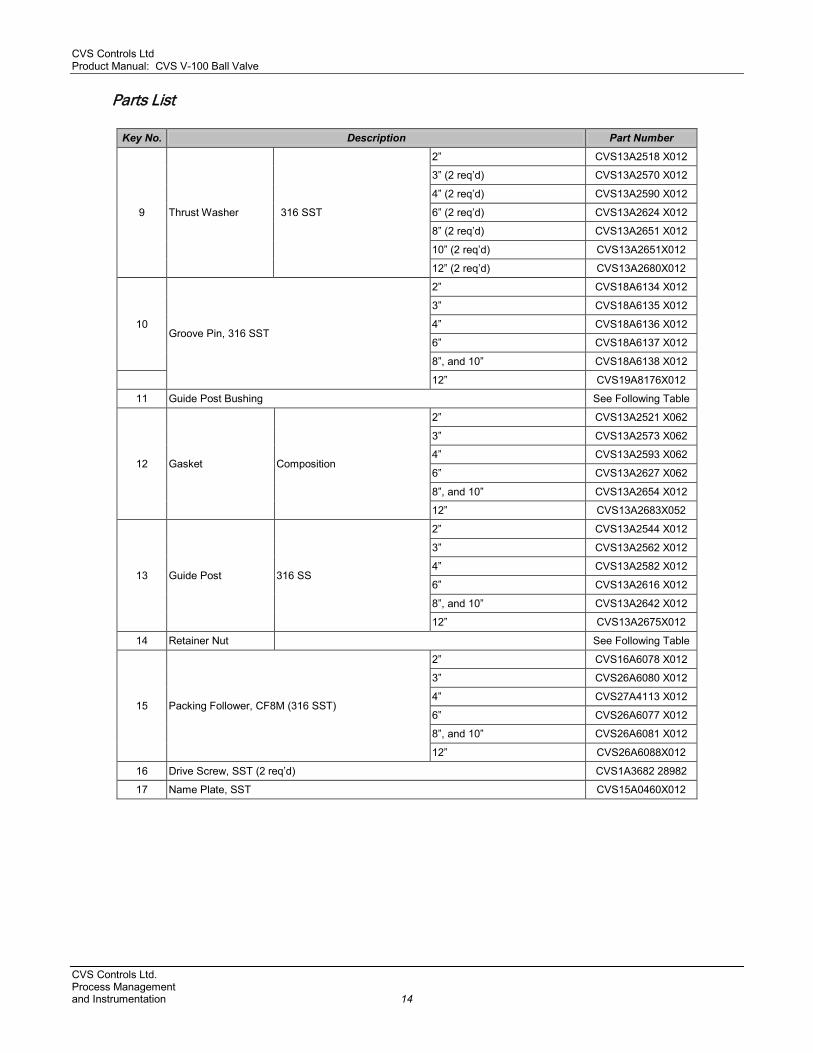
9 Thrust Washer 316 SST
2” CVS13A2518 X012
3” (2 req’d) CVS13A2570 X012
4” (2 req’d) CVS13A2590 X012
6” (2 req’d) CVS13A2624 X012
8” (2 req’d) CVS13A2651 X012
10” (2 req’d) CVS13A2651X012
12” (2 req’d) CVS13A2680X012
10 Groove Pin, 316 SST
2” CVS18A6134 X012
3” CVS18A6135 X012
4” CVS18A6136 X012
6” CVS18A6137 X012
8”, and 10” CVS18A6138 X012
12” CVS19A8176X012
11 Guide Post Bushing See Following Table
12 Gasket Composition
2” CVS13A2521 X062
3” CVS13A2573 X062
4” CVS13A2593 X062
6” CVS13A2627 X062
8”, and 10” CVS13A2654 X012
12” CVS13A2683X052
13 Guide Post 316 SS
2” CVS13A2544 X012
3” CVS13A2562 X012
4” CVS13A2582 X012
6” CVS13A2616 X012
8”, and 10” CVS13A2642 X012
12” CVS13A2675X012
14 Retainer Nut See Following Table
15 Packing Follower, CF8M (316 SST)
2” CVS16A6078 X012
3” CVS26A6080 X012
4” CVS27A4113 X012
6” CVS26A6077 X012
8”, and 10” CVS26A6081 X012
12” CVS26A6088X012
16 Drive Screw, SST (2 req’d) CVS1A3682 28982
17 Name Plate, SST CVS15A0460X012
CVS Controls Ltd. Process Management and Instrumentation 14

CVS Controls Ltd Product Manual: CVS V-100 Ball Valve
Parts List
Key No. Description Part Number
18 Packing Box Ring 316 SST
2” CVS16A6082X012
3” CVS16A6084X012
4” CVS17A5692X012
6” CVS16A6085X012
8”, and 10” CVS16A6086X012
12” CVS16A6087X012
19 Screw, pl steel (2 req’d)
2” CVS1L545428982
3”, and 4” CVS1U7648X0012
6”, and 8” CVS1A560724052
10” and 12” CVS14A5403X012
20 Shim Seal, 316 SST
TCM Ball Seal, 12 req’d
2” CVS17A1965X012
3” CVS17A1966X012
4” CVS17A1967X012
6” CVS17A1968X012
8” CVS17A1969X012
10” CVS17A1970X012
12” CVS17A1971X012
Metal Ball Seal, 12 req’d
2” CVS13A2545X022
3” CVS13A2564X022
4” CVS13A2584X022
6” CVS13A2618X022
8” CVS13A2644X022
10” CVS13A2661X012
12” CVS13A2676X012
21 V- Ball
2” CVS38A6211X042
3” CVS38A6124X052
4” CVS38A6131X052
6” CVS48A6129X052
8” CVS48A6128X052
10” CVS48A6127X052
12” CVS49A8178X052
22 Seal Protector Ring See Following Table
CVS Controls Ltd. Process Management
15 and Instrumentation
CVS Controls Ltd Product Manual: CVS V-100 Ball Valve Parts List
Key No. Description Part Number
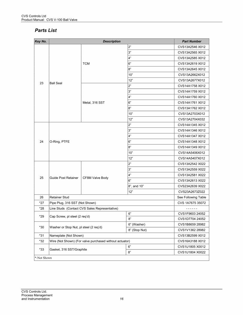
23 Ball Seal
TCM
2” CVS13A2546 X012
3” CVS13A2565 X012
4” CVS13A2585 X012
6” CVS13A2619 X012
8” CVS13A2645 X012
10” CVS13A2662X012
12” CVS13A2677X012
Metal, 316 SST
2” CVS14A1758 X012
3” CVS14A1759 X012
4” CVS14A1760 X012
6” CVS14A1761 X012
8” CVS13A1762 X012
10” CVS13A2703X012
12” CVS13A2704X032
24 O-Ring, PTFE
2” CVS14A1345 X012
3” CVS14A1346 X012
4” CVS14A1347 X012
6” CVS14A1348 X012
8” CVS14A1349 X012
10” CVS14A5406X012
12” CVS14A5407X012
25 Guide Post Retainer CF8M Valve Body
2” CVS13A2542 X022
3” CVS13A2559 X022
4” CVS13A2581 X022
6” CVS13A2613 X022
8”, and 10” CVS23A2639 X022
12” CVS23A2673Z022
26 Retainer Stud See Following Table
*27 Pipe Plug, 316 SST (Not Shown) CVS 1A7675 35072
*28 Line Studs (Contact CVS Sales Representative) - - - - - -
*29 Cap Screw, pl steel (2 req’d) 6” CVS1F9603 24052 8” CVS1D7704 24052
*30 Washer or Stop Nut, pl steel (2 req’d) 6” (Washer) CVS1B8659 28982
8” (Stop Nut) CVS1V1362 28982
*31 Nameplate (Not Shown) CVS13B2599 X012
*32 Wire (Not Shown) (For valve purchased without actuator) CVS16A3188 X012
*33 Gasket, 316 SST/Graphite 6” CVS1U1805 X0012
8” CVS1U1804 X0022
*-Not Shown
CVS Controls Ltd. Process Management and Instrumentation 16
CVS Controls Ltd Product Manual: CVS V-100 Ball Valve
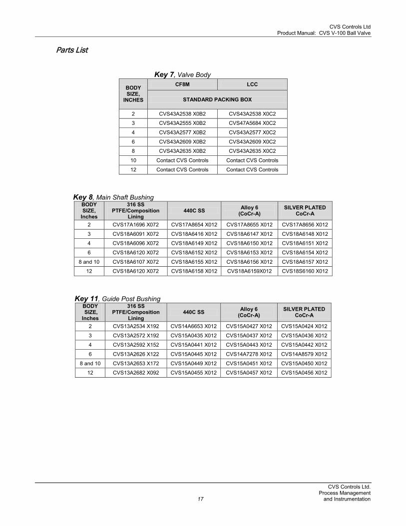
Parts List Key 7, Valve Body
BODY SIZE,
INCHES
CF8M LCC
STANDARD PACKING BOX
2 CVS43A2538 X0B2 CVS43A2538 X0C2
3 CVS43A2555 X0B2 CVS47A5684 X0C2
4 CVS43A2577 X0B2 CVS43A2577 X0C2
6 CVS43A2609 X0B2 CVS43A2609 X0C2
8 CVS43A2635 X0B2 CVS43A2635 X0C2
10 Contact CVS Controls Contact CVS Controls
12 Contact CVS Controls Contact CVS Controls Key 8, Main Shaft Bushing
BODY SIZE,
Inches
316 SS PTFE/Composition
Lining 440C SS Alloy 6
(CoCr-A) SILVER PLATED
CoCr-A
2 CVS17A1696 X072 CVS17A8654 X012 CVS17A8655 X012 CVS17A8656 X012
3 CVS18A6091 X072 CVS18A6416 X012 CVS18A6147 X012 CVS18A6148 X012
4 CVS18A6096 X072 CVS18A6149 X012 CVS18A6150 X012 CVS18A6151 X012
6 CVS18A6120 X072 CVS18A6152 X012 CVS18A6153 X012 CVS18A6154 X012
8 and 10 CVS18A6107 X072 CVS18A6155 X012 CVS18A6156 X012 CVS18A6157 X012
12 CVS18A6120 X072 CVS18A6158 X012 CVS18A6159X012 CVS18S6160 X012 Key 11, Guide Post Bushing
BODY SIZE, Inches
316 SS PTFE/Composition
Lining 440C SS Alloy 6
(CoCr-A) SILVER PLATED
CoCr-A
2 CVS13A2534 X192 CVS14A6653 X012 CVS15A0427 X012 CVS15A0424 X012
3 CVS13A2572 X192 CVS15A0435 X012 CVS15A0437 X012 CVS15A0436 X012
4 CVS13A2592 X152 CVS15A0441 X012 CVS15A0443 X012 CVS15A0442 X012
6 CVS13A2626 X122 CVS15A0445 X012 CVS14A7278 X012 CVS14A8579 X012
8 and 10 CVS13A2653 X172 CVS15A0449 X012 CVS15A0451 X012 CVS15A0450 X012
12 CVS13A2682 X092 CVS15A0455 X012 CVS15A0457 X012 CVS15A0456 X012
CVS Controls Ltd. Process Management
17 and Instrumentation
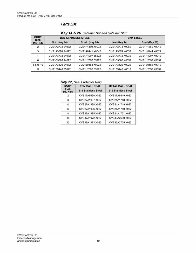
CVS Controls Ltd Product Manual: CVS V-100 Ball Valve Parts List Key 14 & 26, Retainer Nut and Retainer Stud
Key 22, Seal Protector Ring
BODY SIZE,
INCHES
TCM BALL SEAL METAL BALL SEAL
316 Stainless Steel 316 Stainless Steel
2 CVS17A8650 X022 CVS17A8649 X022
3 CVS27A1987 X022 CVS24A1748 X022
4 CVS27A1988 X022 CVS24A1749 X022
6 CVS27A1986 X022 CVS24A1750 X022
8 CVS27A1985 X022 CVS24A1751 X022
10 CVS37A1972 X022 CVS33A2690 X022
12 CVS37A1973 X022 CVS33A2705 X022
BODY SIZE,
INCHES
B8M STAINLESS STEEL B7M STEEL
Nut (Key 14) Stud (Key 26) Nut (Key 14) Stud (Key 26) 2 CVS1A3772 24072 CVS1F4380 X0032 CVS1A3773 X0052 CVS1F4380 X0012
3 CVS1A3374 24072 CVS1A8441 X0042 CVS1A3374 X0052 CVS1V8441 X0022
4 CVS1A3772 24072 CVS1A4207 35222 CVS1A3772 X0032 CVS1A4207 X0012
6 CVS1C3306 24072 CVS1H2597 35222 CVS1C3306 X0052 CVS1H2697 X0032
8 and 10 CVS1A3520 24072 CVS1B9588 X0032 CVS1A3520 X0022 CVS1B9588 X0012
12 CVS1E9446 35072 CVS1H2597 35222 CVS1E9446 X0012 CVS1H2597 X0032
CVS Controls Ltd. Process Management and Instrumentation 18

CVS Controls Ltd Product Manual: CVS V-100 Ball Valve
CVS Controls – V100 Product Bulletin Dimensions: Inches
CVS Controls Ltd.
Process Management 19 and Instrumentation

CVS Controls Ltd Product Manual: CVS V-100 Ball Valve CVS Controls – V100 Product Bulletin Flow coefficients: CVS V100 Line size: valve size=1:1 Valve Size Bore
Flow Coefficient - Cv Pressure Recovery - Km
Valve Rotation – 10o through 90o
10 20 30 40 50 60 70 80 90
2 Inch Full
Cv Km
0.326 - -
4.73 0.865
12.7 0.846
23.3 0.792
39.0 0.740
58.2 0.689
81.5 0.624
112 0.548
163 0.462
3 Inch Full
Cv Km
1.49 - -
7.44 0.792
22.3 0.774
44.6 0.757
73.7 0.723
114 0.672
164 0.593
242 0.533
372 0.462
4 Inch Full
Cv Km
2.30 - -
17.3 0.865
40.3 0.846
74.2 0.792
121 0.740
178 0.672
247 0.593
371 0.504
575 0.372
6 Inch Full
Cv Km
4.64 - -
30.2 0.757
78.9 0.757
148 0.740
231 0.706
331 0.624
463 0.518
664 0.410
1160 0.314
8 Inch Full
Cv Km
5.66 - -
47.8 0.828
120 0.810
225 0.774
354 0.706
512 0.608
749 0.462
1180 0.360
1770 0.281
10 Inch Full
Cv Km
18.6 - -
93.0 0.810
245 0.810
431 0.774
660 0.723
967 0.656
1350 0.578
1860 0.476
3100 0.325
12 Inch Full
Cv Km
39.3 - -
196 0.828
442 0.828
776 0.723
1210 0.672
1640 0.593
2370 0.518
4120 0.436
4910 0.325
CVS V100 Line size: valve size=1.5:1
Valve Size Bore
Flow Coefficient – Cv Pressure Recovery - Km
Valve Rotation – 10o through 90o
10 20 30 40 50 60 70 80 90
2 Inch Full
Cv Km
0.326 - -
4.73 0.865
12.7 0.846
23.2 0.792
38.4 0.740
56.3 0.689
76.4 0.624
99.8 0.548
131 0.462
3 Inch Full
Cv Km
1.49 - -
7.44 0.792
22.3 0.774
44.5 0.757
73.1 0.723
112 0.672
157 0.593
222 0.533
311 0.462
4 Inch Full
Cv Km
2.30 - -
17.3 0.865
40.2 0.846
73.8 0.792
119 0.740
173 0.672
235 0.593
333 0.504
457 0.372
6 Inch Full
Cv Km
4.64 - -
30.2 0.757
78.9 0.757
148 0.740
230 0.706
326 0.624
450 0.518
625 0.410
1040 0.314
8 Inch Full
Cv Km
5.66 - -
47.8 0.828
120 0.810
224 0.774
351 0.706
503 0.608
723 0.462
1080 0.360
1490 0.281
10 Inch Full
Cv Km
18.6 - -
93.0 0.810
245 0.810
429 0.774
653 0.723
944 0.656
1290 0.578
1710 0.476
2520 0.325
12 Inch Full
Cv Km
39.3 - -
196 0.828
441 0.828
771 0.723
1190 0.672
1590 0.593
2230 0.518
3390 0.436
3940 0.325
CVS Controls Ltd. Process Management and Instrumentation 20

CVS Controls Ltd Product Manual: CVS V-100 Ball Valve
Notes:
CVS Controls Ltd. Process Management
21 and Instrumentation

CVS Controls Ltd Product Manual: CVS V-100 Ball Valve
Notes:
CVS Controls Ltd. Process Management and Instrumentation 22
CVS Controls Ltd Product Manual: CVS V-100 Ball Valve
Notes:
CVS Controls Ltd. strives for the highest levels of quality and accuracy. The information included in this publication is presented for informational purposes only. CVS Controls Ltd. reserves the right to modify or change, and improve design, process, and specifications without written notice. Under no circumstance is the information contained to be interpreted to be a guarantee/warranty with regard to our products or services, applicability or use. Selection, use and maintenance are the sole responsibility of the end user and purchaser. CVS Controls assumes no liability for the selection use and maintenance of any product.
CVS Controls Ltd. Process Management
23 and Instrumentation

CVS Controls Ltd Product Manual: CVS V-100 Ball Valve
Head Office 3900 – 101 Street
Edmonton, Alberta, Canada T6E 0A5 Office: (780) 437-3055 Fax: (780) 436-5461
Calgary Sales Office 3516 114 Avenue SE
Calgary, Alberta, Canada T2Z 3V6 Office: (403) 250-1416 Fax: (403) 291-9487
Website: www.cvs-controls.com E-Mail: [email protected] Printed in Canada
Rev 3, October 2013
CVS Controls Ltd. Process Management and Instrumentation 24