cutting data for boring with big kaiser
DESCRIPTION
GIVES COMPREHENSIVE DATA FOR FINE BORING WITH BIG KAISER BORING HEADS. HOWEVER THIS DATA CAN ALSO BE USED AS REFENCE FOR OTHER BORING HEADSTRANSCRIPT
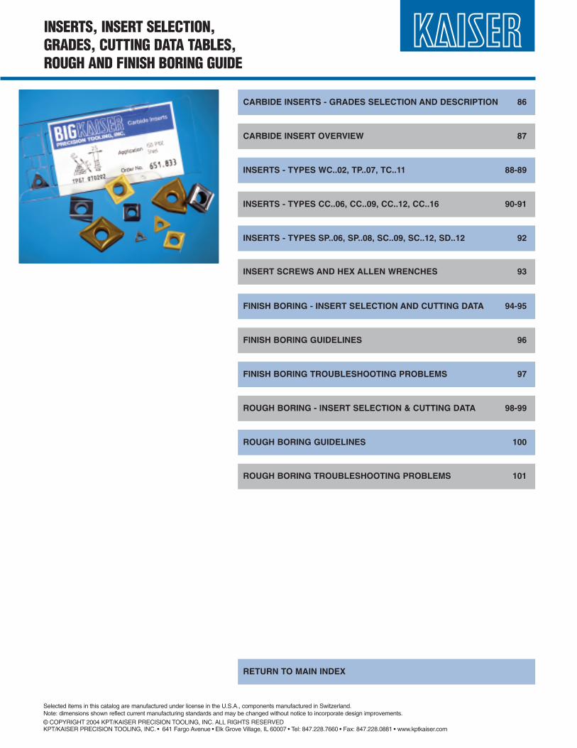
INSERTS, INSERT SELECTION,GRADES, CUTTING DATA TABLES,ROUGH AND FINISH BORING GUIDE
CARBIDE INSERTS - GRADES SELECTION AND DESCRIPTION 86
CARBIDE INSERT OVERVIEW 87
INSERTS - TYPES WC..02, TP..07, TC..11 88-89
INSERTS - TYPES CC..06, CC..09, CC..12, CC..16 90-91
INSERT SCREWS AND HEX ALLEN WRENCHES 93
INSERTS - TYPES SP..06, SP..08, SC..09, SC..12, SD..12 92
FINISH BORING - INSERT SELECTION AND CUTTING DATA 94-95
FINISH BORING GUIDELINES 96
FINISH BORING TROUBLESHOOTING PROBLEMS 97
ROUGH BORING - INSERT SELECTION & CUTTING DATA 98-99
ROUGH BORING GUIDELINES 100
ROUGH BORING TROUBLESHOOTING PROBLEMS 101
RETURN TO MAIN INDEX
Selected items in this catalog are manufactured under license in the U.S.A., components manufactured in Switzerland.Note: dimensions shown reflect current manufacturing standards and may be changed without notice to incorporate design improvements.© COPYRIGHT 2004 KPT/KAISER PRECISION TOOLING, INC. ALL RIGHTS RESERVEDKPT/KAISER PRECISION TOOLING, INC. • 641 Fargo Avenue • Elk Grove Village, IL 60007 • Tel: 847.228.7660 • Fax: 847.228.0881 • www.kptkaiser.com
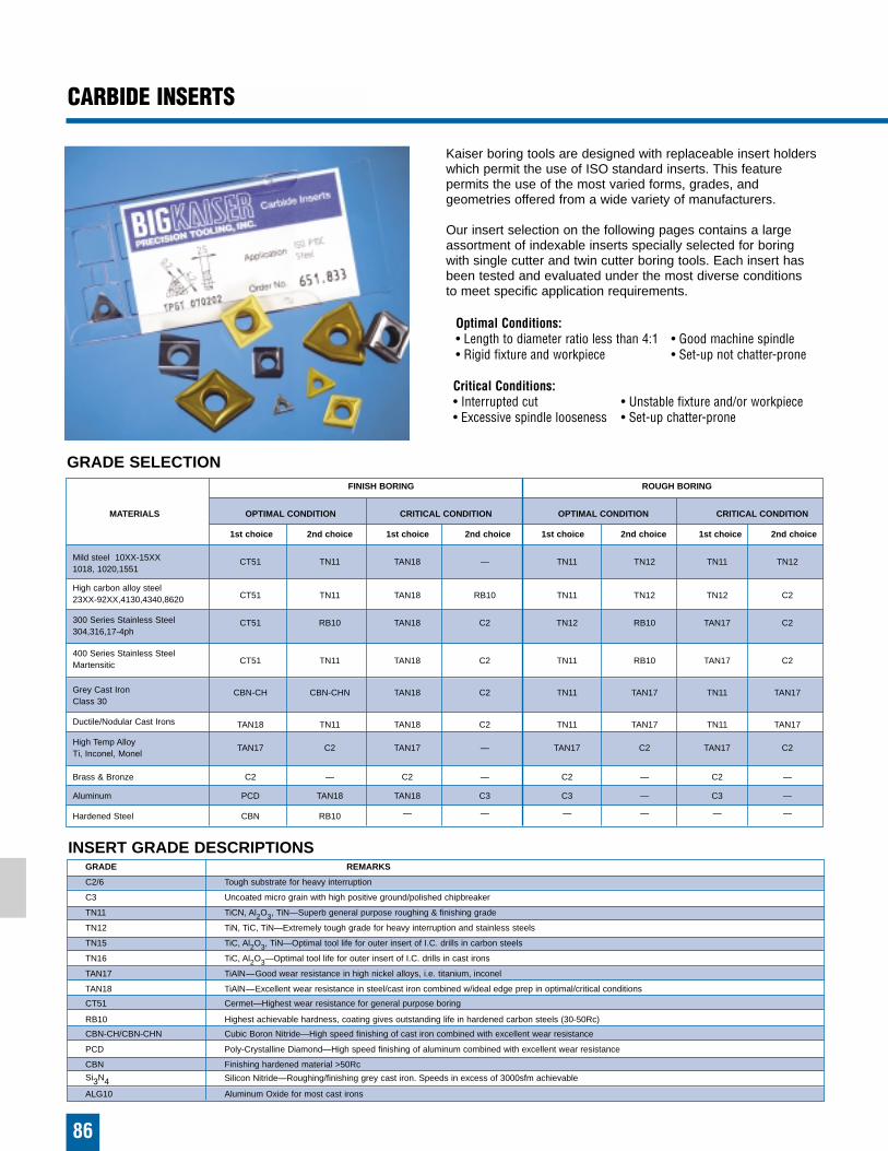
FINISH BORING ROUGH BORING
MATERIALS OPTIMAL CONDITION CRITICAL CONDITION OPTIMAL CONDITION CRITICAL CONDITION
1st choice 2nd choice 1st choice 2nd choice 1st choice 2nd choice 1st choice 2nd choice
Mild steel 10XX-15XX CT51 TN11 TAN18 — TN11 TN12 TN11 TN121018, 1020,1551
High carbon alloy steel23XX-92XX,4130,4340,8620 CT51 TN11 TAN18 RB10 TN11 TN12 TN12 C2
300 Series Stainless Steel CT51 RB10 TAN18 C2 TN12 RB10 TAN17 C2304,316,17-4ph
400 Series Stainless SteelCT51 TN11 TAN18 C2 TN11 RB10 TAN17 C2Martensitic
Grey Cast Iron CBN-CH CBN-CHN TAN18 C2 TN11 TAN17 TN11 TAN17Class 30
Ductile/Nodular Cast Irons TAN18 TN11 TAN18 C2 TN11 TAN17 TN11 TAN17
High Temp AlloyTAN17 C2 TAN17 — TAN17 C2 TAN17 C2
Ti, Inconel, Monel
Brass & Bronze C2 — C2 — C2 — C2 —
Aluminum PCD TAN18 TAN18 C3 C3 — C3 —
Hardened Steel CBN RB10 — — — — — —
86
CARBIDE INSERTS
INSERT GRADE DESCRIPTIONS
GRADE SELECTION
Kaiser boring tools are designed with replaceable insert holderswhich permit the use of ISO standard inserts. This feature permits the use of the most varied forms, grades, and geometries offered from a wide variety of manufacturers.
Our insert selection on the following pages contains a largeassortment of indexable inserts specially selected for boring with single cutter and twin cutter boring tools. Each insert hasbeen tested and evaluated under the most diverse conditions to meet specific application requirements.
Optimal Conditions:• Length to diameter ratio less than 4:1 • Good machine spindle• Rigid fixture and workpiece • Set-up not chatter-prone
Critical Conditions:• Interrupted cut • Unstable fixture and/or workpiece• Excessive spindle looseness • Set-up chatter-prone
GRADE REMARKS
C2/6 Tough substrate for heavy interruption
C3 Uncoated micro grain with high positive ground/polished chipbreaker
TN11 TiCN, Al2O3, TiN—Superb general purpose roughing & finishing grade
TN12 TiN, TiC, TiN—Extremely tough grade for heavy interruption and stainless steels
TN15 TiC, Al2O3, TiN—Optimal tool life for outer insert of I.C. drills in carbon steels
TN16 TiC, Al2O3—Optimal tool life for outer insert of I.C. drills in cast irons
TAN17 TiAlN—Good wear resistance in high nickel alloys, i.e. titanium, inconel
TAN18 TiAlN—Excellent wear resistance in steel/cast iron combined w/ideal edge prep in optimal/critical conditions
CT51 Cermet—Highest wear resistance for general purpose boring
RB10 Highest achievable hardness, coating gives outstanding life in hardened carbon steels (30-50Rc)
CBN-CH/CBN-CHN Cubic Boron Nitride—High speed finishing of cast iron combined with excellent wear resistance
PCD Poly-Crystalline Diamond—High speed finishing of aluminum combined with excellent wear resistance
CBN Finishing hardened material >50Rc
Si3N4 Silicon Nitride—Roughing/finishing grey cast iron. Speeds in excess of 3000sfm achievable
ALG10 Aluminum Oxide for most cast irons
CARBIDE INSERT OVERVIEW
87
11.654.858
11.654.864
10.654.877
10.654.888
11.654.898
11.654.840
11.654.850
11.654.860
11.654.853
11.654.869
11.654.856
11.654.865
11.654.867
11.654.868
11.654.845
11.938.847
11.938.842
11.938.835
11.654.841
11.654.957
11.654.958
10.654.977
10.654.987
11.654.940
11.654.952
11.654.943
11.654.953
11.654.959
11.654.960
11.654.968
11.654.969
11.654.974
10.938.843
10.938.851
11.938.838
11.654.951
11.654.989
11.654.991
10.654.995
10.654.992
11.654.993
11.654.990
11.654.983
11.654.984
11.654.978
11.654.979
10.938.871
10.938.862
11.654.980
10.654.997
10.654.998
11.654.996
11.656.370
11.654.344
11.654.359
10.654.387
11.654.350
11.654.360
11.654.353
11.654.364
10.688.619
10.651.823
10.651.723
11.651.923
11.651.909
10.651.802
10.651.702
11.651.907
10.651.824
10.651.833
10.651.734
10.938.840
11.938.831
10.938.837
10.938.836
11.655.315
11.655.325
11.655.335
10.655.378
10.655.388
10.655.398
11.655.311
11.655.321
11.655.331
11.655.316
11.655.336
11.656.352
11.655.322
11.655.332
11.655.356
11.655.355
10.655.373
10.655.383
10.655.393
10.938.841
11.938.860
10.938.834
10.938.865
4,6
1,5
1,2
3,4
1,2
5,6
1,3
1,10
7,10
2,10
WC..02 TP..07 TC..11 CC..06 CC..09 CC..12 CC..16 SC..09 SC..12
GRADE: C2UNCOATED CARBIDE
CAST IRONBRASSBRONZEHIGH TEMP. ALLOYS
GRADE: C3GUNCOATED CARBIDE
ALUMINUMMAGNESIUMPLASTIC
GRADES: TNP11/TNP15COATED CARBIDE
STEELCAST IRON
GRADE: TNP12COATED CARBIDE
STEELSTAINLESS STEEL
GRADE: CTP51/52CERMET
STEELSTAINLESS STEELCAST IRON
GRADES: TAN17/TNP16COATED CARBIDESTEELHIGH ALLOY STEELSCAST IRON
GRADE: TAN18COATED CARBIDE
STEELSTAINLESS STEELCAST IRONALUMINUM
GRADES: PCD, PCD-CBPOLY-CRYSTALLINE
DIAMONDALUMINUMMAGNESIUM
GRADES: CBN, CBN-CHCUBIC BORON NITRIDE
CAST IRONHARDENED STEEL
GRADES: Si3N4SILICON NITRIDE
CAST IRON
FINISH BORING ROUGH BORING
GRADEMATERIAL GROUP
11.654.249
11.654.259
10.654.277
10.654.287
11.654.240
11.654.250
11.654.247
11.654.200
APPLICATION CODES:1. Normal working conditions, rigid tool combination, workpiece well clamped2. High production boring at high speed under favorable conditions3. Unfavorable conditions, long tools, unstable workpiece or fixtures4. Boring with interrupted cutting, impact loading5. Boring or drilling of non-ferrous materials6. Boring cast iron, nickel based, or high temp. alloys7. Boring of hardened steel alloys (min. Rc50)8. Boring of structural and alloyed steels9. Boring of stainless steels and long chipping materials10. High speed boring
APPLCODES
R= .008”R= .008” R= .016”
R= .031”
R= .008”
R= .016”
R= .031”
R= .008”
R= .016”
R= .031”
R= .016”
R= .031”
R= .008”
R= .016”
R= .031”
R= .016”
R= .016”
R= .008”
R= .016”
R= .016”
R= .016” R= .031”
R= .031”
R= .031”
R= .016”
R= .031”
R= .031”
R= .016”
R= .031”
R= .016”
R= .031”
R= .016”
R= .031”
R= .016”
R= .031”
R= .016”
R= .031”
R= .016” R= .016”
R= .031”
R= .016”
R= .031”
R= .016”
R= .031”
R= .016”
R= .031”
R= .016”
R= .031”
R= .031”
R= .031”
R= .031”
R= .031”
R= .016”
R= .031”
R= .016”
R= .031”
R= .031”
R= .031”
R= .031”
R= .031”
R= .031”
R= .031”
R= .031” R= .031”
R= .031”
R= .031”
R= .031”
R= .016”
R= .031”
R= .031”
R= .016”
R= .016”
R= .031”
R= .004”
R= .008”
R= .008”
R= .008”
11.655.605
10.655.605
10.655.601
11.655.607
10.655.600
11.655.606
10.655.605
10.655.603
11.938.845
11.938.846
11.938.863
R= .016”
R= .004”
R= .008”
R= .008”
R= .008”
R= .008” R= .012”
R= .012”
R= .012”
R= .012”
R= .016”
R= .008”
R= .004”
R= .012”
R= .016”
R= .008”
R= .012”
R= .031”
R= .012”
R= .004” R= .008”
R= .016”
R= .031”
R= .008”
R= .016”
R= .031”
R= .016”
R= .031”
R= .008”
R= .016”
R= .031”
R= .008”
R= .016”
R= .008”
R= .016”
R= .031”
R= .016”
R= .031”
R= .016”
R= .031”
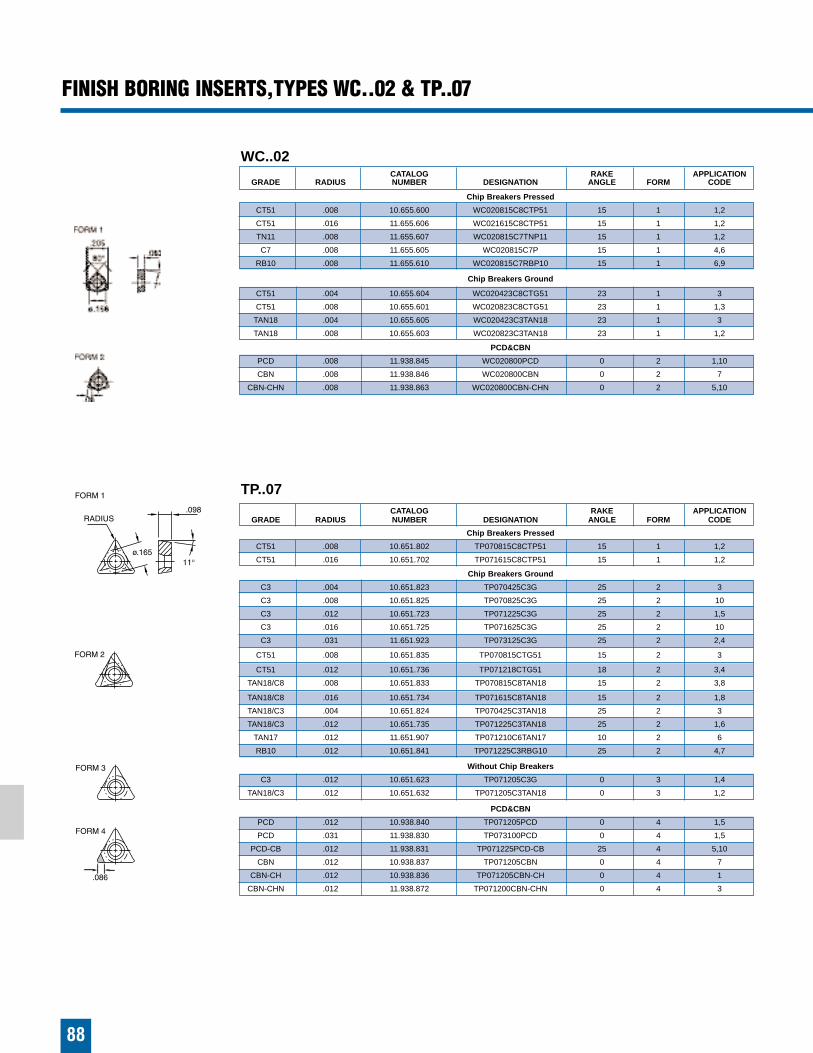
88
FINISH BORING INSERTS,TYPES WC..02 & TP..07
�
WC..02CATALOG RAKE APPLICATION
GRADE RADIUS NUMBER DESIGNATION ANGLE FORM CODE
Chip Breakers Pressed
CT51 .008 10.655.600 WC020815C8CTP51 15 1 1,2
CT51 .016 11.655.606 WC021615C8CTP51 15 1 1,2
TN11 .008 11.655.607 WC020815C7TNP11 15 1 1,2
C7 .008 11.655.605 WC020815C7P 15 1 4,6
RB10 .008 11.655.610 WC020815C7RBP10 15 1 6,9
Chip Breakers Ground
CT51 .004 10.655.604 WC020423C8CTG51 23 1 3
CT51 .008 10.655.601 WC020823C8CTG51 23 1 1,3
TAN18 .004 10.655.605 WC020423C3TAN18 23 1 3
TAN18 .008 10.655.603 WC020823C3TAN18 23 1 1,2
PCD&CBN
PCD .008 11.938.845 WC020800PCD 0 2 1,10
CBN .008 11.938.846 WC020800CBN 0 2 7
CBN-CHN .008 11.938.863 WC020800CBN-CHN 0 2 5,10
TP..07CATALOG RAKE APPLICATION
GRADE RADIUS NUMBER DESIGNATION ANGLE FORM CODE
Chip Breakers Pressed
CT51 .008 10.651.802 TP070815C8CTP51 15 1 1,2
CT51 .016 10.651.702 TP071615C8CTP51 15 1 1,2
Chip Breakers Ground
C3 .004 10.651.823 TP070425C3G 25 2 3
C3 .008 10.651.825 TP070825C3G 25 2 10
C3 .012 10.651.723 TP071225C3G 25 2 1,5
C3 .016 10.651.725 TP071625C3G 25 2 10
C3 .031 11.651.923 TP073125C3G 25 2 2,4
CT51 .008 10.651.835 TP070815CTG51 15 2 3
CT51 .012 10.651.736 TP071218CTG51 18 2 3,4
TAN18/C8 .008 10.651.833 TP070815C8TAN18 15 2 3,8
TAN18/C8 .016 10.651.734 TP071615C8TAN18 15 2 1,8
TAN18/C3 .004 10.651.824 TP070425C3TAN18 25 2 3
TAN18/C3 .012 10.651.735 TP071225C3TAN18 25 2 1,6
TAN17 .012 11.651.907 TP071210C6TAN17 10 2 6
RB10 .012 10.651.841 TP071225C3RBG10 25 2 4,7
Without Chip Breakers
C3 .012 10.651.623 TP071205C3G 0 3 1,4
TAN18/C3 .012 10.651.632 TP071205C3TAN18 0 3 1,2
PCD&CBN
PCD .012 10.938.840 TP071205PCD 0 4 1,5
PCD .031 11.938.830 TP073100PCD 0 4 1,5
PCD-CB .012 11.938.831 TP071225PCD-CB 25 4 5,10
CBN .012 10.938.837 TP071205CBN 0 4 7
CBN-CH .012 10.938.836 TP071205CBN-CH 0 4 1
CBN-CHN .012 11.938.872 TP071200CBN-CHN 0 4 3
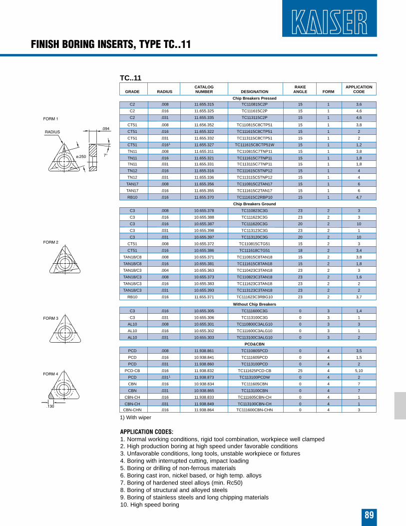
TC..11CATALOG RAKE APPLICATION
GRADE RADIUS NUMBER DESIGNATION ANGLE FORM CODE
Chip Breakers Pressed
C2 .008 11.655.315 TC110815C2P 15 1 3,6
C2 .016 11.655.325 TC111615C2P 15 1 4,6
C2 .031 11.655.335 TC113115C2P 15 1 4,6
CT51 .008 11.656.352 TC110815C8CTP51 15 1 3,8
CT51 .016 11.655.322 TC111615C8CTP51 15 1 2
CT51 .031 11.655.332 TC113115C8CTP51 15 1 2
CT51 .0161 11.655.327 TC111615C8CTP51W 15 1 1,2
TN11 .008 11.655.311 TC110815C7TNP11 15 1 3,8
TN11 .016 11.655.321 TC111615C7TNP11 15 1 1,8
TN11 .031 11.655.331 TC113115C7TNP11 15 1 1,8
TN12 .016 11.655.316 TC111615C5TNP12 15 1 4
TN12 .031 11.655.336 TC113115C5TNP12 15 1 4
TAN17 .008 11.655.356 TC110815C2TAN17 15 1 6
TAN17 .016 11.655.355 TC111615C2TAN17 15 1 6
RB10 .016 11.655.370 TC111615C2RBP10 15 1 4,7
Chip Breakers Ground
C3 .008 10.655.378 TC110823C3G 23 2 3
C3 .016 10.655.388 TC111623C3G 23 2 3
C3 .016 10.655.387 TC111620C3G 20 2 10
C3 .031 10.655.398 TC113123C3G 23 2 1
C3 .031 10.655.397 TC113120C3G 20 2 10
CT51 .008 10.655.372 TC110815CTG51 15 2 3
CT51 .016 10.655.386 TC111618CTG51 18 2 3,4
TAN18/C8 .008 10.655.371 TC110815C8TAN18 15 2 3,8
TAN18/C8 .016 10.655.381 TC111615C8TAN18 15 2 1,8
TAN18/C3 .004 10.655.363 TC110423C3TAN18 23 2 3
TAN18/C3 .008 10.655.373 TC110823C3TAN18 23 2 1,6
TAN18/C3 .016 10.655.383 TC111623C3TAN18 23 2 2
TAN18/C3 .031 10.655.393 TC113123C3TAN18 23 2 2
RB10 .016 11.655.371 TC111623C3RBG10 23 2 3,7
Without Chip Breakers
C3 .016 10.655.305 TC111600C3G 0 3 1,4
C3 .031 10.655.306 TC113100C3G 0 3 1
AL10 .008 10.655.301 TC110800C3ALG10 0 3 3
AL10 .016 10.655.302 TC111600C3ALG10 0 3 1
AL10 .031 10.655.303 TC113100C3ALG10 0 3 2
PCD&CBN
PCD .008 11.938.861 TC110805PCD 0 4 3,5
PCD .016 10.938.841 TC111605PCD 0 4 1,5
PCD .031 11.938.860 TC113100PCD 0 4 2
PCD-CB .016 11.938.832 TC111625PCD-CB 25 4 5,10
PCD .0311 11.938.873 TC113100PCDW 0 4 2
CBN .016 10.938.834 TC111605CBN 0 4 7
CBN .031 10.938.865 TC113100CBN 0 4 7
CBN-CH .016 11.938.833 TC111605CBN-CH 0 4 1
CBN-CH .031 11.938.849 TC113100CBN-CH 0 4 1
CBN-CHN .016 11.938.864 TC111600CBN-CHN 0 4 3
1) With wiper
FINISH BORING INSERTS, TYPE TC..11
89
APPLICATION CODES:1. Normal working conditions, rigid tool combination, workpiece well clamped2. High production boring at high speed under favorable conditions3. Unfavorable conditions, long tools, unstable workpiece or fixtures4. Boring with interrupted cutting, impact loading5. Boring or drilling of non-ferrous materials6. Boring cast iron, nickel based, or high temp. alloys7. Boring of hardened steel alloys (min. Rc50)8. Boring of structural and alloyed steels9. Boring of stainless steels and long chipping materials10. High speed boring
90
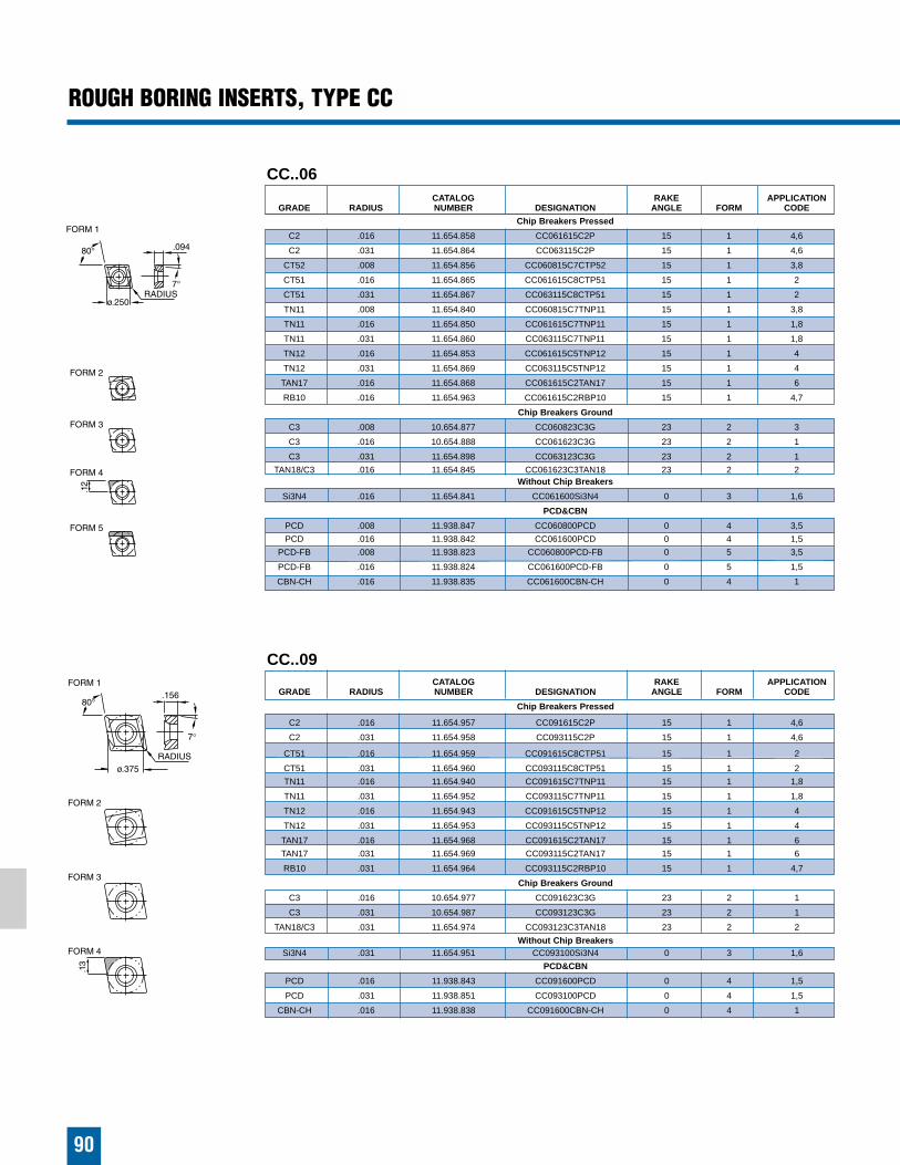
ROUGH BORING INSERTS, TYPE CC
CC..06CATALOG RAKE APPLICATION
GRADE RADIUS NUMBER DESIGNATION ANGLE FORM CODE
Chip Breakers Pressed
C2 .016 11.654.858 CC061615C2P 15 1 4,6
C2 .031 11.654.864 CC063115C2P 15 1 4,6
CT52 .008 11.654.856 CC060815C7CTP52 15 1 3,8
CT51 .016 11.654.865 CC061615C8CTP51 15 1 2
CT51 .031 11.654.867 CC063115C8CTP51 15 1 2
TN11 .008 11.654.840 CC060815C7TNP11 15 1 3,8
TN11 .016 11.654.850 CC061615C7TNP11 15 1 1,8
TN11 .031 11.654.860 CC063115C7TNP11 15 1 1,8
TN12 .016 11.654.853 CC061615C5TNP12 15 1 4
TN12 .031 11.654.869 CC063115C5TNP12 15 1 4
TAN17 .016 11.654.868 CC061615C2TAN17 15 1 6
RB10 .016 11.654.963 CC061615C2RBP10 15 1 4,7
Chip Breakers Ground
C3 .008 10.654.877 CC060823C3G 23 2 3
C3 .016 10.654.888 CC061623C3G 23 2 1
C3 .031 11.654.898 CC063123C3G 23 2 1
TAN18/C3 .016 11.654.845 CC061623C3TAN18 23 2 2Without Chip Breakers
Si3N4 .016 11.654.841 CC061600Si3N4 0 3 1,6
PCD&CBN
PCD .008 11.938.847 CC060800PCD 0 4 3,5
PCD .016 11.938.842 CC061600PCD 0 4 1,5
PCD-FB .008 11.938.823 CC060800PCD-FB 0 5 3,5
PCD-FB .016 11.938.824 CC061600PCD-FB 0 5 1,5
CBN-CH .016 11.938.835 CC061600CBN-CH 0 4 1
CC..09CATALOG RAKE APPLICATION
GRADE RADIUS NUMBER DESIGNATION ANGLE FORM CODE
Chip Breakers Pressed
C2 .016 11.654.957 CC091615C2P 15 1 4,6
C2 .031 11.654.958 CC093115C2P 15 1 4,6
CT51 .016 11.654.959 CC091615C8CTP51 15 1 2
CT51 .031 11.654.960 CC093115C8CTP51 15 1 2
TN11 .016 11.654.940 CC091615C7TNP11 15 1 1,8
TN11 .031 11.654.952 CC093115C7TNP11 15 1 1,8
TN12 .016 11.654.943 CC091615C5TNP12 15 1 4
TN12 .031 11.654.953 CC093115C5TNP12 15 1 4
TAN17 .016 11.654.968 CC091615C2TAN17 15 1 6
TAN17 .031 11.654.969 CC093115C2TAN17 15 1 6
RB10 .031 11.654.964 CC093115C2RBP10 15 1 4,7
Chip Breakers Ground
C3 .016 10.654.977 CC091623C3G 23 2 1
C3 .031 10.654.987 CC093123C3G 23 2 1
TAN18/C3 .031 11.654.974 CC093123C3TAN18 23 2 2
Without Chip BreakersSi3N4 .031 11.654.951 CC093100Si3N4 0 3 1,6
PCD&CBN
PCD .016 11.938.843 CC091600PCD 0 4 1,5
PCD .031 11.938.851 CC093100PCD 0 4 1,5
CBN-CH .016 11.938.838 CC091600CBN-CH 0 4 1
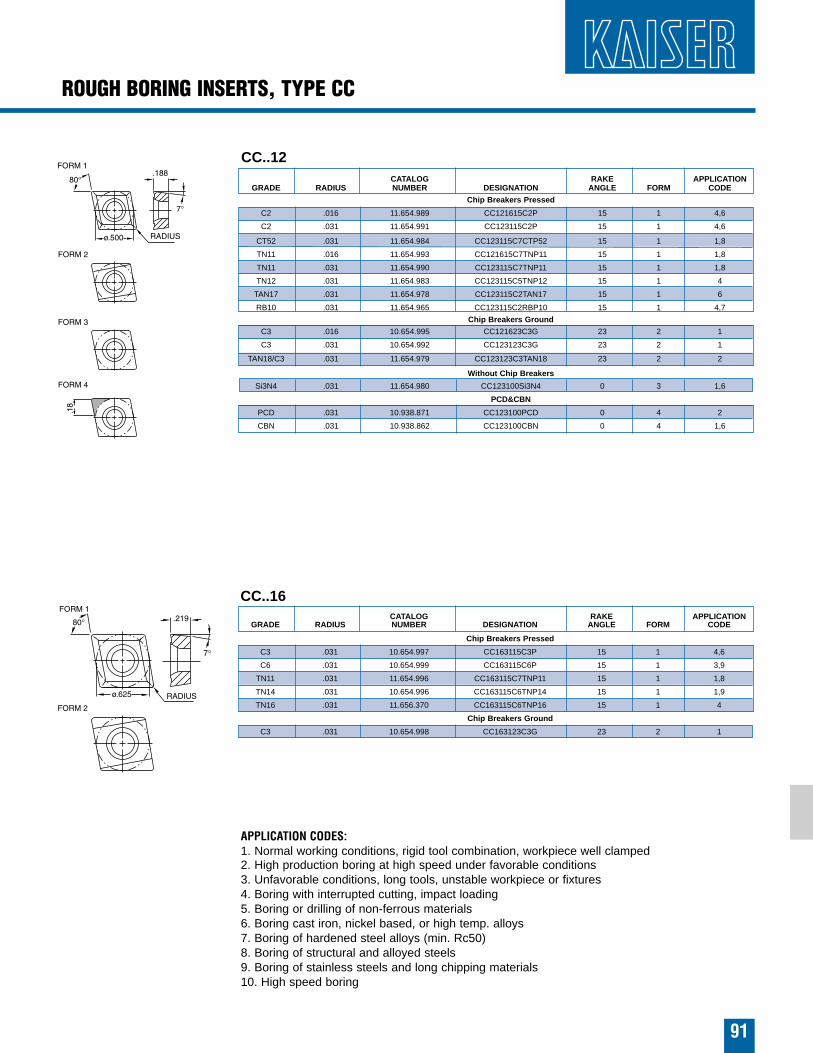
ROUGH BORING INSERTS, TYPE CC
91
CC..16CATALOG RAKE APPLICATION
GRADE RADIUS NUMBER DESIGNATION ANGLE FORM CODE
Chip Breakers Pressed
C3 .031 10.654.997 CC163115C3P 15 1 4,6
C6 .031 10.654.999 CC163115C6P 15 1 3,9
TN11 .031 11.654.996 CC163115C7TNP11 15 1 1,8
TN14 .031 10.654.996 CC163115C6TNP14 15 1 1,9
TN16 .031 11.656.370 CC163115C6TNP16 15 1 4
Chip Breakers Ground
C3 .031 10.654.998 CC163123C3G 23 2 1
CC..12CATALOG RAKE APPLICATION
GRADE RADIUS NUMBER DESIGNATION ANGLE FORM CODE
Chip Breakers Pressed
C2 .016 11.654.989 CC121615C2P 15 1 4,6
C2 .031 11.654.991 CC123115C2P 15 1 4,6
CT52 .031 11.654.984 CC123115C7CTP52 15 1 1,8
TN11 .016 11.654.993 CC121615C7TNP11 15 1 1,8
TN11 .031 11.654.990 CC123115C7TNP11 15 1 1,8
TN12 .031 11.654.983 CC123115C5TNP12 15 1 4
TAN17 .031 11.654.978 CC123115C2TAN17 15 1 6
RB10 .031 11.654.965 CC123115C2RBP10 15 1 4,7
Chip Breakers Ground
C3 .016 10.654.995 CC121623C3G 23 2 1
C3 .031 10.654.992 CC123123C3G 23 2 1
TAN18/C3 .031 11.654.979 CC123123C3TAN18 23 2 2
Without Chip Breakers
Si3N4 .031 11.654.980 CC123100Si3N4 0 3 1,6
PCD&CBN
PCD .031 10.938.871 CC123100PCD 0 4 2
CBN .031 10.938.862 CC123100CBN 0 4 1,6
APPLICATION CODES:1. Normal working conditions, rigid tool combination, workpiece well clamped2. High production boring at high speed under favorable conditions3. Unfavorable conditions, long tools, unstable workpiece or fixtures4. Boring with interrupted cutting, impact loading5. Boring or drilling of non-ferrous materials6. Boring cast iron, nickel based, or high temp. alloys7. Boring of hardened steel alloys (min. Rc50)8. Boring of structural and alloyed steels9. Boring of stainless steels and long chipping materials10. High speed boring

92
SC..12CATALOG RAKE APPLICATION
GRADE RADIUS NUMBER DESIGNATION ANGLE FORM CODE
C2 .016 11.654.344 SC121615C2P 15 1 4,6
C2 .031 11.654.359 SC123115C2P 15 1 4.6
TN11 .016 11.654.340 SC121615C7TNP11 15 1 1,8
TN11 .031 11.654.350 SC123115C7TNP11 15 1 1.8
TN12 .047 11.654.360 SC124715C7TNP11 15 1 4
TN12 .031 11.654.353 SC123115C5TNP12 15 1 4
TAN17 .031 11.654.364 SC123115C2TAN17 15 1 6
RB10 .031 11.654.365 SC123115C2RBP10 15 1 4,7
Chip Breakers Ground
C3 .031 10.654.387 SC123123C3G 23 2 1
ROUGH BORING INSERTS, TYPES SP..06, SP..08, SC..09, SC..12, SD..12
SP..08CATALOG RAKE APPLICATION
GRADE RADIUS NUMBER DESIGNATION ANGLE FORM CODE
Chip Breakers Ground
C3 .020 10.854.187 SP082023C3G 23 1 1
C6 .020 10.654.183 SP082010C6G 10 1 1,8
Without Chip Breakers
C2 .020 10.654.128 SP082005C2G 0 2 1
156
375
SD..12CATALOG RAKE APPLICATION
GRADE RADIUS NUMBER DESIGNATION ANGLE FORM CODE
SI3N4 .031 10.688.619 SD123100SI3N4 0 1 1
SI3N4 CHMFR 10.688.599 SD123100SI3N4 0 2 1
SC..09CATALOG RAKE APPLICATION
GRADE RADIUS NUMBER DESIGNATION ANGLE FORM CODE
Chip Breakers Pressed
C2 .016 11.654.249 SC091615C2P 15 1 4,6
C6 031 11.654.259 SC093115C2P 15 1 4,6
TN11 .016 11.654.240 SC091615C7TNP11 15 1 1,8
TN11 .031 11.654.250 SC093115C7TNP11 15 1 4
TN12 .016 11.654.247 SC091615C5TNP12 15 1 4
TN12 .031 11.654.200 SC093115C5TNP12 15 1 4
Chip Breakers Ground
C3 .016 10.654.277 SC091623C3G 23 2 3
C3 .031 10.654.287 SC093123C3G 23 2 1
SP..06CATALOG RAKE APPLICATION
GRADE RADIUS NUMBER DESIGNATION ANGLE FORM CODE
Chip Breakers Pressed
TN11 .008 10.654.140 SP060815C7TNP11 15 1 3,8
TN11 .016 10.654.150 SP061615C7TNP11 15 1 1,8
TN16 .016 10.654.152 SP061615C2TNP16 15 1 4
C2 .016 10.654.158 SP061615C2P 15 1 4,6
Chip Breakers Ground
C3 .016 10.654.168 SP061623C3G 23 2 1
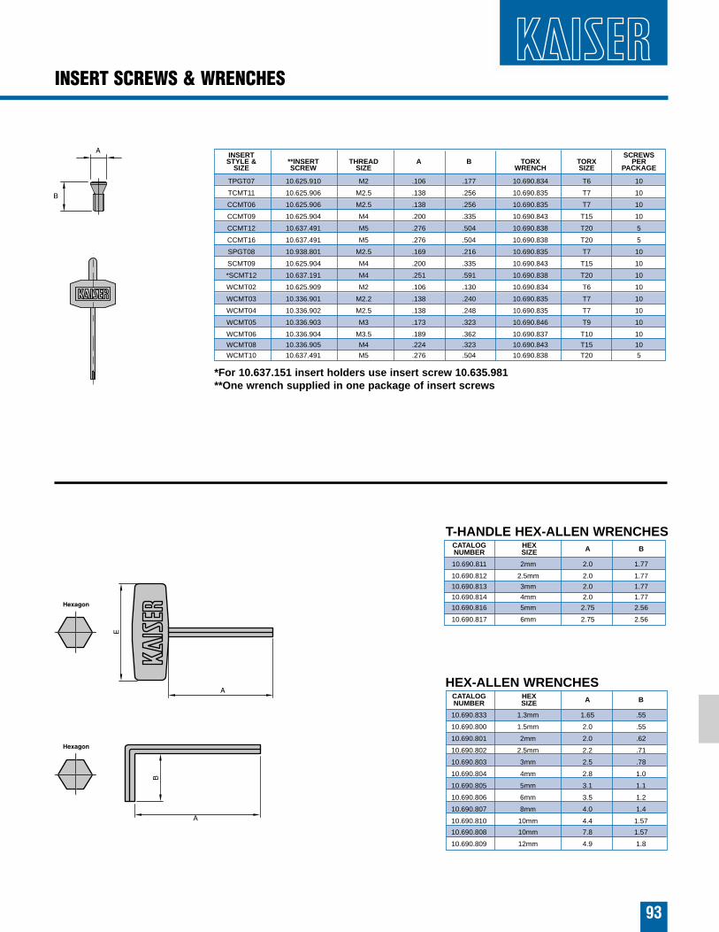
HEX-ALLEN WRENCHESCATALOG HEX A BNUMBER SIZE
10.690.833 1.3mm 1.65 .55
10.690.800 1.5mm 2.0 .55
10.690.801 2mm 2.0 .62
10.690.802 2.5mm 2.2 .71
10.690.803 3mm 2.5 .78
10.690.804 4mm 2.8 1.0
10.690.805 5mm 3.1 1.1
10.690.806 6mm 3.5 1.2
10.690.807 8mm 4.0 1.4
10.690.810 10mm 4.4 1.57
10.690.808 10mm 7.8 1.57
10.690.809 12mm 4.9 1.8
INSERT SCREWSSTYLE & **INSERT THREAD A B TORX TORX PER
SIZE SCREW SIZE WRENCH SIZE PACKAGE
TPGT07 10.625.910 M2 .106 .177 10.690.834 T6 10
TCMT11 10.625.906 M2.5 .138 .256 10.690.835 T7 10
CCMT06 10.625.906 M2.5 .138 .256 10.690.835 T7 10
CCMT09 10.625.904 M4 .200 .335 10.690.843 T15 10
CCMT12 10.637.491 M5 .276 .504 10.690.838 T20 5
CCMT16 10.637.491 M5 .276 .504 10.690.838 T20 5
SPGT08 10.938.801 M2.5 .169 .216 10.690.835 T7 10
SCMT09 10.625.904 M4 .200 .335 10.690.843 T15 10
*SCMT12 10.637.191 M4 .251 .591 10.690.838 T20 10
WCMT02 10.625.909 M2 .106 .130 10.690.834 T6 10
WCMT03 10.336.901 M2.2 .138 .240 10.690.835 T7 10
WCMT04 10.336.902 M2.5 .138 .248 10.690.835 T7 10
WCMT05 10.336.903 M3 .173 .323 10.690.846 T9 10
WCMT06 10.336.904 M3.5 .189 .362 10.690.837 T10 10
WCMT08 10.336.905 M4 .224 .323 10.690.843 T15 10
WCMT10 10.637.491 M5 .276 .504 10.690.838 T20 5
INSERT SCREWS & WRENCHES
93
*For 10.637.151 insert holders use insert screw 10.635.981**One wrench supplied in one package of insert screws
T-HANDLE HEX-ALLEN WRENCHESCATALOG HEX A BNUMBER SIZE
10.690.811 2mm 2.0 1.77
10.690.812 2.5mm 2.0 1.77
10.690.813 3mm 2.0 1.77
10.690.814 4mm 2.0 1.77
10.690.816 5mm 2.75 2.56
10.690.817 6mm 2.75 2.56
CAUTION
94
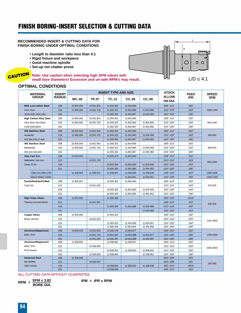
RECOMMENDED INSERT & CUTTING DATA FOR FINISH BORING UNDER OPTIMAL CONDITIONS
• Length to diameter ratio less than 4:1• Rigid fixture and workpiece• Good machine spindle• Set-up not chatter prone
Note: Use caution when selecting high SFM values with small bore diameters! Excessive and un-safe RPM’s may result.
FINISH BORING-INSERT SELECTION & CUTTING DATA
IPM = IPR x RPMRPM = SFM x 3.82BORE DIA.
OPTIMAL CONDITIONS
L/D ≤ 4:1
MATERIAL INSERT INSERT TYPE AND SIZE STOCK FEED SPEEDGROUP RADIUS
WC..02 TP..07 TC..11 CC..06 CC..09ALLOW. IPR SFMON DIA.
Mild, Low-carbon Steel .008 10.655.600 10.651.802 11.656.352 11.654.856 .008"-.012" .002"
10xx-15xx .016 11.655.606 10.651.702 11.655.322 11.654.865 11.654.959 .016"-.020" .004" 1000-1450
1018,1020,1551,A36 .031 11.655.332 11.654.867 11.654.960 .024"-.040" .006"
High Carbon Alloy Steel .008 10.655.600 10.651.802 11.656.352 11.654.856 .008"-.012" .002"
23xx-92xx,Tool Steel .016 11.655.606 10.651.702 11.655.322 11.654.865 11.654.959 .016"-.020" .004" 800-1100
4140,4340,8620 .031 11.655.332 11.654.867 11.654.960 .024"-.040" .006"
300 Stainless Steel .008 10.655.600 10.651.802 11.656.352 11.654.856 .008"-.012" .002"
Austenitic .016 11.655.606 10.651.702 11.655.322 11.654.865 11.654.959 .016"-.020" .004" 550-800
303,304,316,17-4ph .031 11.655.332 11.654.867 11.654.960 .024"-.040" .006"
400 Stainless Steel .008 10.655.600 10.651.802 11.656.352 11.654.856 .008"-.012" .002"
Martensitic .016 11.655.606 10.651.702 11.655.322 11.654.865 11.654.959 .016"-.020" .004" 650-875
403,410,416,430 .031 11.655.332 11.654.867 11.654.960 .024"-.040" .006"
Grey Cast Iron .008 10.655.603 10.655.373 11.654.840 .008"-.012" .002"
Malleable Cast Iron .012 10.651.735 .010"-.014" .003"650-1000
Class 20,30 .016 10.655.383 11.654.850 11.654.940 .016"-.020" .004"
.031 10.655.393 11.654.860 11.654.952 .024"-.050" .006"
CBN-CH,CBN-CHN 11.938.863 11.938.872 11.938.833 11.938.835 11.938.838 .008"-.016" .003" 1500-2000
Silicon Nitride Si3N4 11.654.841 11.654.951 .016"-.026" .005" 1000-1200
Ductile/Nodular/Chilled .008 11.655.607 10.655.301 11.654.840 .008"-.012" .002"
Cast Iron .012 10.651.632 .010"-.014" .003" 375-625
.016 10.655.302 11.654.850 11.654.940 .016"-.020" .004"
.031 10.655.303 11.654.860 11.654.952 .024"-.040" .006"
High Temp. Alloys .008 11.655.605 11.655.356 .006"-.010" .0015"
Titanium,Inconel,Monel .012 11.651.907 .008"-.012" .002"200-325
.016 11.655.355 11.654.868 11.654.968 .012"-.016" .002"
.031 11.654.969 .018"-.032" .003"
Copper Alloys .008 11.655.605 11.655.315 .008"-.012" .002"
Brass, Bronze .012 10.651.623 .010"-.014" .003"1100-1800
.016 11.655.325 11.654.858 11.654.957 .016"-.020" .004"
.031 11.655.335 11.654.864 11.654.958 .024"-.050" .006"
Aluminum/Magnesium .008 10.655.603 10.651.825 10.655.378 10.654.877 .008"-.012" .002"
6061,7075 .016 10.651.725 10.655.387 10.654.888 10.654.977 .016"-.020" .004" 1200-1600
.031 11.651.923 10.655.397 10.654.898 10.654.987 .024"-.040" .006"Aluminum/Magnesium .008 11.938.845 11.938.861 11.938.847 .008"-.012" .002"
6061,7075 .012 10.938.840 .010"-.014" .003"2000-4000
PCD Inserts .016 10.938.841 11.938.842 11.938.843 .016"-.020" .004"
.031 11.938.830 11.938.860 11.938.851 .024"-.050" .006"
Hardened Steel .008 11.938.846 .004"-.008" .001"
Min.50HRc .012 10.938.837 .004"-.008" .001"200-300
CBN Inserts .016 10.938.834 11.938.835 11.938.838 .005"-.010" .0015"
.031 10.938.865 .006"-.012" .002"
ALL CUTTING DATA WITHOUT GUARANTEE
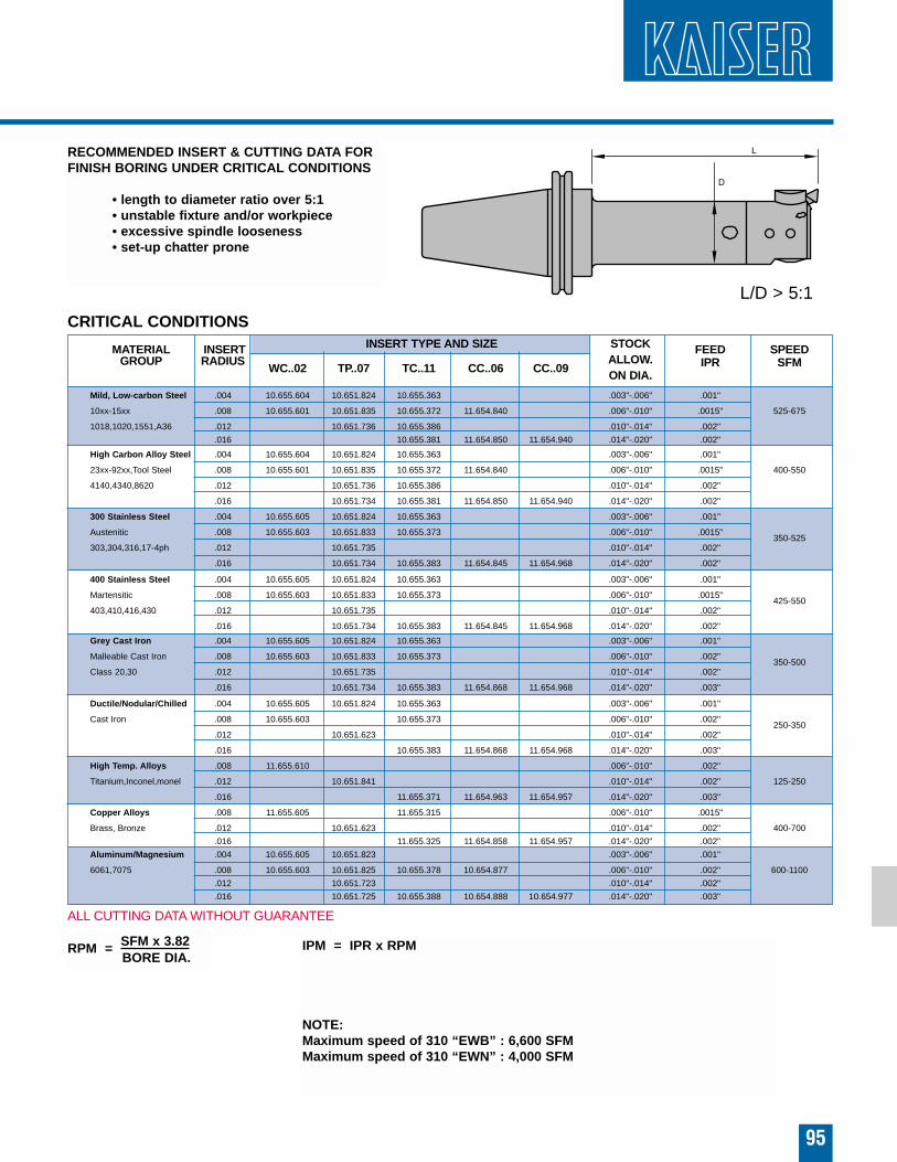
MATERIAL INSERT INSERT TYPE AND SIZE STOCK FEED SPEEDGROUP RADIUS
WC..02 TP..07 TC..11 CC..06 CC..09ALLOW. IPR SFMON DIA.
Mild, Low-carbon Steel .004 10.655.604 10.651.824 10.655.363 .003"-.006" .001"
10xx-15xx .008 10.655.601 10.651.835 10.655.372 11.654.840 .006"-.010" .0015" 525-675
1018,1020,1551,A36 .012 10.651.736 10.655.386 .010"-.014" .002"
.016 10.655.381 11.654.850 11.654.940 .014"-.020" .002"
High Carbon Alloy Steel .004 10.655.604 10.651.824 10.655.363 .003"-.006" .001"
23xx-92xx,Tool Steel .008 10.655.601 10.651.835 10.655.372 11.654.840 .006"-.010" .0015" 400-550
4140,4340,8620 .012 10.651.736 10.655.386 .010"-.014" .002"
.016 10.651.734 10.655.381 11.654.850 11.654.940 .014"-.020" .002"
300 Stainless Steel .004 10.655.605 10.651.824 10.655.363 .003"-.006" .001"
Austenitic .008 10.655.603 10.651.833 10.655.373 .006"-.010" .0015"350-525
303,304,316,17-4ph .012 10.651.735 .010"-.014" .002"
.016 10.651.734 10.655.383 11.654.845 11.654.968 .014"-.020" .002"
400 Stainless Steel .004 10.655.605 10.651.824 10.655.363 .003"-.006" .001"
Martensitic .008 10.655.603 10.651.833 10.655.373 .006"-.010" .0015"425-550
403,410,416,430 .012 10.651.735 .010"-.014" .002"
.016 10.651.734 10.655.383 11.654.845 11.654.968 .014"-.020" .002"
Grey Cast Iron .004 10.655.605 10.651.824 10.655.363 .003"-.006" .001"
Malleable Cast Iron .008 10.655.603 10.651.833 10.655.373 .006"-.010" .002"350-500
Class 20,30 .012 10.651.735 .010"-.014" .002"
.016 10.651.734 10.655.383 11.654.868 11.654.968 .014"-.020" .003"
Ductile/Nodular/Chilled .004 10.655.605 10.651.824 10.655.363 .003"-.006" .001"
Cast Iron .008 10.655.603 10.655.373 .006"-.010" .002"250-350
.012 10.651.623 .010"-.014" .002"
.016 10.655.383 11.654.868 11.654.968 .014"-.020" .003"
High Temp. Alloys .008 11.655.610 .006"-.010" .002"
Titanium,Inconel,monel .012 10.651.841 .010"-.014" .002" 125-250
.016 11.655.371 11.654.963 11.654.957 .014"-.020" .003"
Copper Alloys .008 11.655.605 11.655.315 .006"-.010" .0015"
Brass, Bronze .012 10.651.623 .010"-.014" .002" 400-700
.016 11.655.325 11.654.858 11.654.957 .014"-.020" .002"
Aluminum/Magnesium .004 10.655.605 10.651.823 .003"-.006" .001"
6061,7075 .008 10.655.603 10.651.825 10.655.378 10.654.877 .006"-.010" .002" 600-1100
.012 10.651.723 .010"-.014" .002"
.016 10.651.725 10.655.388 10.654.888 10.654.977 .014"-.020" .003"
95
RECOMMENDED INSERT & CUTTING DATA FORFINISH BORING UNDER CRITICAL CONDITIONS
• length to diameter ratio over 5:1• unstable fixture and/or workpiece• excessive spindle looseness• set-up chatter prone
RPM = SFM x 3.82 IPM = IPR x RPM
NOTE:Maximum speed of 310 “EWB” : 6,600 SFMMaximum speed of 310 “EWN” : 4,000 SFM
BORE DIA.
CRITICAL CONDITIONS
L/D > 5:1
ALL CUTTING DATA WITHOUT GUARANTEE
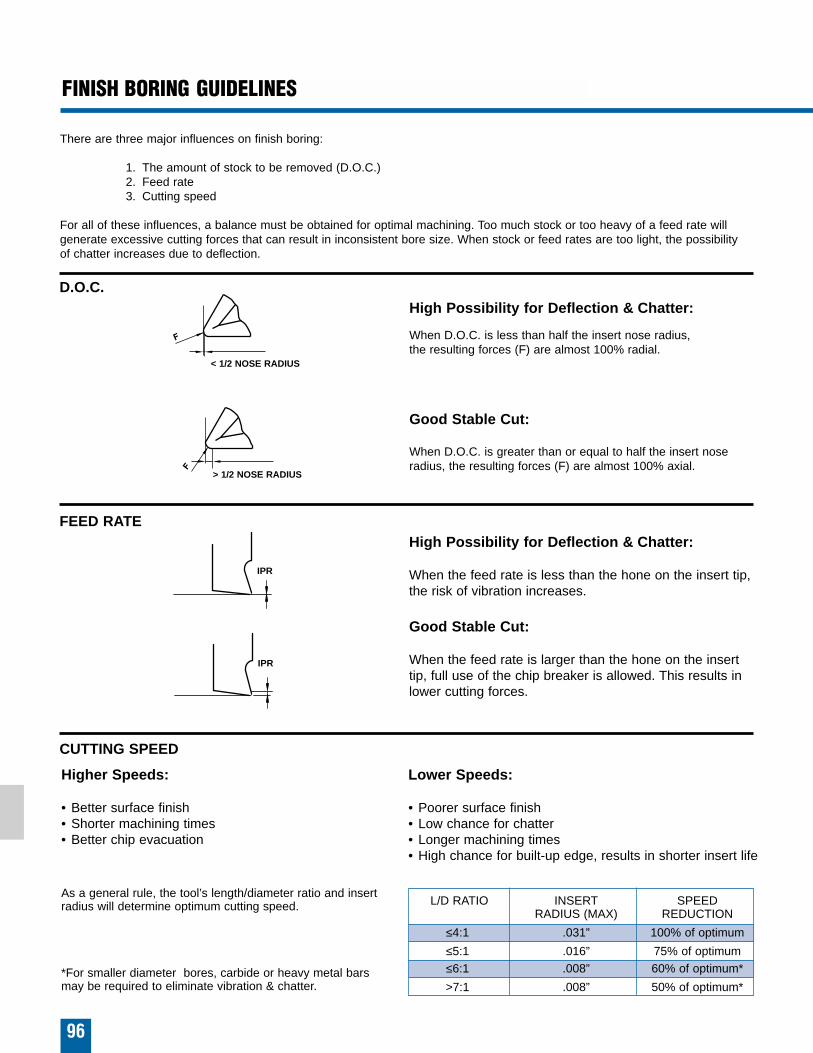
L/D RATIO INSERT SPEEDRADIUS (MAX) REDUCTION
≤4:1 .031” 100% of optimum
≤5:1 .016” 75% of optimum≤6:1 .008” 60% of optimum*
>7:1 .008” 50% of optimum*
96
FINISH BORING GUIDELINES
There are three major influences on finish boring:
1. The amount of stock to be removed (D.O.C.)2. Feed rate3. Cutting speed
For all of these influences, a balance must be obtained for optimal machining. Too much stock or too heavy of a feed rate willgenerate excessive cutting forces that can result in inconsistent bore size. When stock or feed rates are too light, the possibility of chatter increases due to deflection.
High Possibility for Deflection & Chatter:
When D.O.C. is less than half the insert nose radius, the resulting forces (F) are almost 100% radial.
Good Stable Cut:
When D.O.C. is greater than or equal to half the insert noseradius, the resulting forces (F) are almost 100% axial.
High Possibility for Deflection & Chatter:
When the feed rate is less than the hone on the insert tip,the risk of vibration increases.
Good Stable Cut:
When the feed rate is larger than the hone on the inserttip, full use of the chip breaker is allowed. This results inlower cutting forces.
Lower Speeds:
• Poorer surface finish• Low chance for chatter• Longer machining times• High chance for built-up edge, results in shorter insert life
Higher Speeds:
• Better surface finish• Shorter machining times• Better chip evacuation
< 1/2 NOSE RADIUS
> 1/2 NOSE RADIUS
IPR
IPR
D.O.C.
FEED RATE
CUTTING SPEED
As a general rule, the tool’s length/diameter ratio and insertradius will determine optimum cutting speed.
*For smaller diameter bores, carbide or heavy metal bars may be required to eliminate vibration & chatter.
97
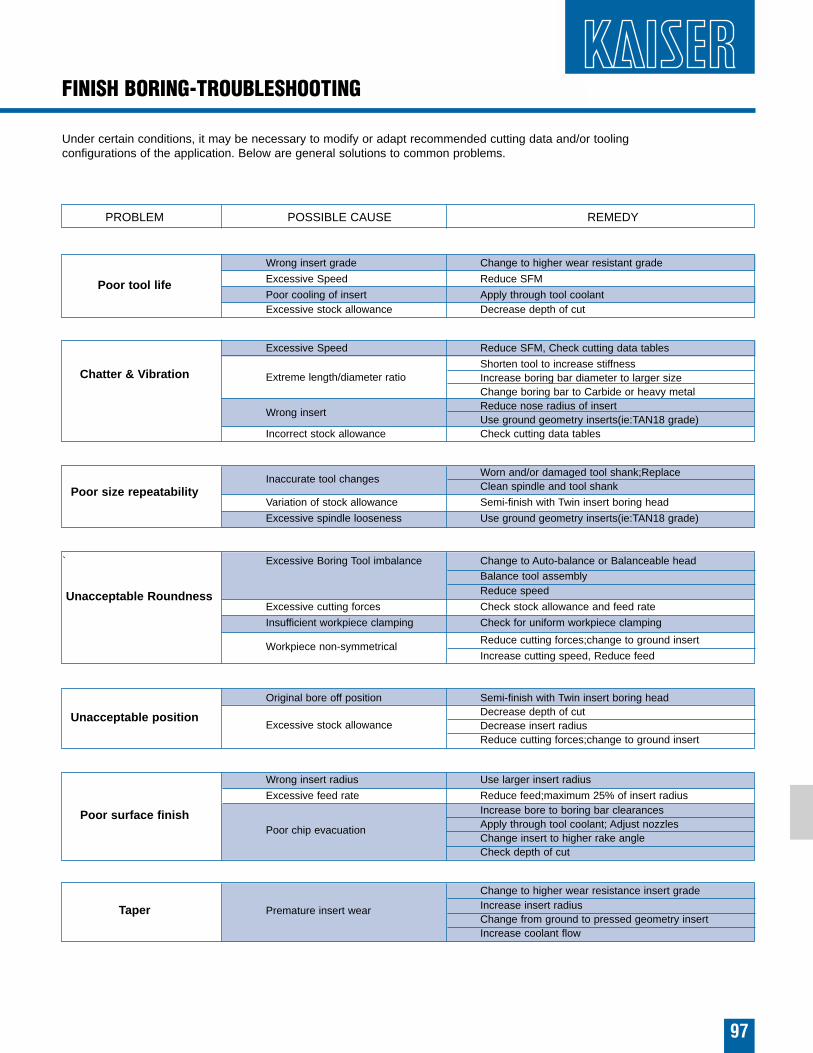
FINISH BORING-TROUBLESHOOTING
PROBLEM POSSIBLE CAUSE REMEDY
Poor tool life
Wrong insert grade Change to higher wear resistant grade
Excessive Speed Reduce SFM
Poor cooling of insert Apply through tool coolantExcessive stock allowance Decrease depth of cut
Chatter & Vibration
Excessive Speed Reduce SFM, Check cutting data tables
Extreme length/diameter ratioShorten tool to increase stiffnessIncrease boring bar diameter to larger sizeChange boring bar to Carbide or heavy metal
Wrong insertReduce nose radius of insertUse ground geometry inserts(ie:TAN18 grade)
Incorrect stock allowance Check cutting data tables
Poor size repeatabilityInaccurate tool changes
Worn and/or damaged tool shank;ReplaceClean spindle and tool shank
Variation of stock allowance Semi-finish with Twin insert boring head
Excessive spindle looseness Use ground geometry inserts(ie:TAN18 grade)
`
Unacceptable Roundness
Excessive Boring Tool imbalance Change to Auto-balance or Balanceable headBalance tool assemblyReduce speed
Excessive cutting forces Check stock allowance and feed rate
Insufficient workpiece clamping Check for uniform workpiece clamping
Workpiece non-symmetricalReduce cutting forces;change to ground insert
Increase cutting speed, Reduce feed
Unacceptable position
Original bore off position Semi-finish with Twin insert boring head
Excessive stock allowanceDecrease depth of cutDecrease insert radiusReduce cutting forces;change to ground insert
Poor surface finish
Wrong insert radius Use larger insert radius
Excessive feed rate Reduce feed;maximum 25% of insert radius
Poor chip evacuation
Increase bore to boring bar clearancesApply through tool coolant; Adjust nozzlesChange insert to higher rake angleCheck depth of cut
Taper Premature insert wear
Change to higher wear resistance insert gradeIncrease insert radiusChange from ground to pressed geometry insertIncrease coolant flow
Under certain conditions, it may be necessary to modify or adapt recommended cutting data and/or tooling configurations of the application. Below are general solutions to common problems.
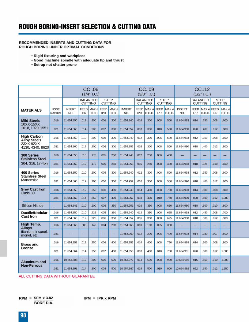
CC..06(1/4" I.C.)
CC..09(3/8" I.C.)
CC..12(1/2" I.C.)
.016 11.654.850 .012 .200 .006 .300 11.654.940 .014 .300 .008 .500 11.654.993 .014 .350 .008 .600
.031 11.654.860 .014 .200 .007 .300 11.654.952 .018 .300 .010 .500 11.654.990 .020 .400 .012 .800
.016 11.654.850 .010 .200 .005 .300 11.654.940 .012 .300 .006 .500 11.654.993 .012 .350 .008 .600
.031 11.654.860 .012 .200 .006 .300 11.654.952 .016 .300 .008 .500 11.654.990 .018 .400 .012 .800
.016 11.654.853 .010 .170 .005 .250 11.654.943 .012 .250 .006 .450 — — — — —
.031 11.654.869 .012 .170 .006 .250 11.654.953 .016 .250 .008 .450 11.654.983 .018 .325 .010 .600
.016 11.654.850 .010 .200 .005 .300 11.654.940 .012 .300 .006 .500 11.654.993 .012 .350 .008 .600
.031 11.654.860 .012 .200 .006 .300 11.654.952 .016 .300 .008 .500 11.654.990 .018 .400 .012 .800
.016 11.654.850 .012 .250 .006 .400 11.654.940 .014 .400 .008 .750 11.654.993 .014 .500 .008 .800
.031 11.654.860 .014 .250 .007 .400 11.654.952 .018 .400 .010 .750 11.654.990 .020 .600 .012 1.000
_ 11.654.841 .010 .200 .005 .350 11.654.951 .016 .350 .008 .650 11.654.980 .018 .500 .010 .800
.016 11.654.850 .010 .225 .005 .350 11.654.940 .012 .350 .006 .625 11.654.993 .012 .450 .008 .700
.031 11.654.860 .012 .225 .006 .350 11.654.952 .016 .350 .008 .625 11.654.990 .018 .500 .012 .900
.016 11.654.868 .008 .140 .004 .200 11.654.968 .010 .180 .005 .350 — — — — —
.031 — — — — — 11.654.969 .012 .200 .006 .400 11.654.978 .014 .280 .007 .500
.016 11.654.858 .012 .250 .006 .400 11.654.957 .014 .400 .008 .750 11.654.989 .014 .500 .008 .800
.031 11.654.864 .014 .250 .007 .400 11.654.958 .018 .400 .010 .750 11.654.991 .020 .600 .012 1.000
.016 10.654.888 .012 .300 .006 .500 10.654.977 .014 .500 .008 .900 10.654.995 .016 .550 .010 1.000
.031 11.654.898 .014 .300 .008 .500 10.654.987 .018 .500 .010 .900 10.654.992 .022 .650 .012 1.250
RECOMMENDED INSERTS AND CUTTING DATA FORROUGH BORING UNDER OPTIMAL CONDITIONS
• Rigid fixturing and workpiece• Good machine spindle with adequate hp and thrust• Set-up not chatter prone
Mild Steels10XX-15XX1018, 1020, 1551
MATERIALS
High CarbonAlloy Steels23XX-92XX4130, 4340, 8620
300 Series Stainless Steel304, 316, 17-4ph
Grey Cast IronClass 30
Silicon Nitride
Ductile/NodularCast Iron
400 Series Stainless SteelMartensitic
High Temp.Alloystitanium, inconel,monel, etc.
Brass and Bronze
Aluminum andNon-Ferrous
NOSERADIUS
INSERTNO.
FEEDIPR
MAX øD.O.C.
FEEDIPR
MAX øD.O.C.
98
INSERTNO.
FEEDIPR
MAX øD.O.C.
FEEDIPR
MAX øD.O.C.
INSERTNO.
FEEDIPR
MAX øD.O.C.
FEEDIPR
MAX øD.O.C.
BALANCEDCUTTING
STEPCUTTING
BALANCEDCUTTING
STEPCUTTING
BALANCEDCUTTING
STEPCUTTING
ROUGH BORING-INSERT SELECTION & CUTTING DATA
RPM = SFM x 3.82 IPM = IPR x RPMBORE DIA.
ALL CUTTING DATA WITHOUT GUARANTEE
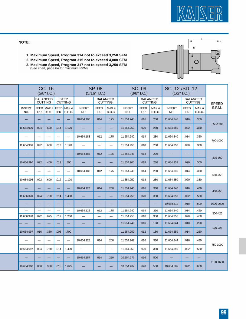
— — — — — 10.654.183 .014 .175 11.654.240 .016 .280 11.654.340 .016 .350
850-120011.654.996 .024 .600 .014 1.120 — — — 11.654.250 .020 .280 11.654.350 .022 .380
— — — — — 10.654.183 .012 .175 11.654.240 .014 .280 11.654.340 .014 .350700-1000
11.654.996 .022 .600 .012 1.120 — — — 11.654.250 .018 .280 11.654.350 .020 .380
— — — — — 10.654.183 .012 .125 11.654.247 .014 .230 — — —375-600
10.654.996 .022 .400 .012 .800 — — — 11.654.200 .018 .230 11.654.353 .020 .300
— — — — — 10.654.183 .012 .175 11.654.240 .014 .280 11.654.340 .014 .350500-750
10.654.996 .022 .600 .012 1.120 — — — 11.654.250 .018 .280 11.654.350 .020 .380
— — — — — 10.654.128 .014 .200 11.654.240 .016 .380 11.654.340 .016 .480450-750
11.656.370 .024 .750 .014 1.400 — — — 11.654.250 .020 .380 11.654.350 .022 .580
— — — — — — — — — — — 10.688.619 .018 .500 1000-2000
— — — — — 10.654.128 .012 .175 11.654.240 .014 .330 11.654.340 .014 .420300-425
11.656.370 .022 .675 .012 1.250 — — — 11.654.250 .018 .330 11.654.350 .020 .480
— — — — — — — — 11.654.249 .010 .160 11.654.344 .010 .200
100-22510.654.997 .016 .380 .008 .700 — — — 11.654.259 .012 .180 11.654.359 .014 .250
— — — — — 10.654.128 .014 .200 11.654.249 .016 .380 11.654.344 .016 .480
750-1000
10.654.997 .024 .750 .014 1.400 — — — 11.654.259 .020 .380 11.654.359 .022 .580
— — — — — 10.654.187 .014 .250 10.654.277 .016 .500 — — —
1100-1600
10.654.998 .030 .900 .015 1.625 — — — 10.654.287 .020 .500 10.654.387 .022 .650
99
SPEEDS.F.M.
CC..16(5/8" I.C.)
SP..08(5/16" I.C.)
SC..09 SC..12 /SD..12(3/8" I.C.) (1/2" I.C.)
INSERTNO.
FEEDIPR
MAX øD.O.C.
FEEDIPR
MAX øD.O.C.
INSERTNO.
FEEDIPR
MAX øD.O.C.
BALANCEDCUTTING
STEPCUTTING
BALANCEDCUTTING
INSERTNO.
FEEDIPR
MAX øD.O.C.
BALANCEDCUTTING
INSERTNO.
FEEDIPR
MAX øD.O.C.
BALANCEDCUTTING
NOTE:
1. Maximum Speed, Program 314 not to exceed 3,250 SFM2. Maximum Speed, Program 315 not to exceed 4,000 SFM3. Maximum Speed, Program 317 not to exceed 3,250 SFM
(See chart, page 64 for maximum RPM)
MATERIAL K FACTOR*Steel 0.75
Alloy Steel 1.0Cast Iron 0.65
Aluminum 0.43High Temp Alloys 2.0
100
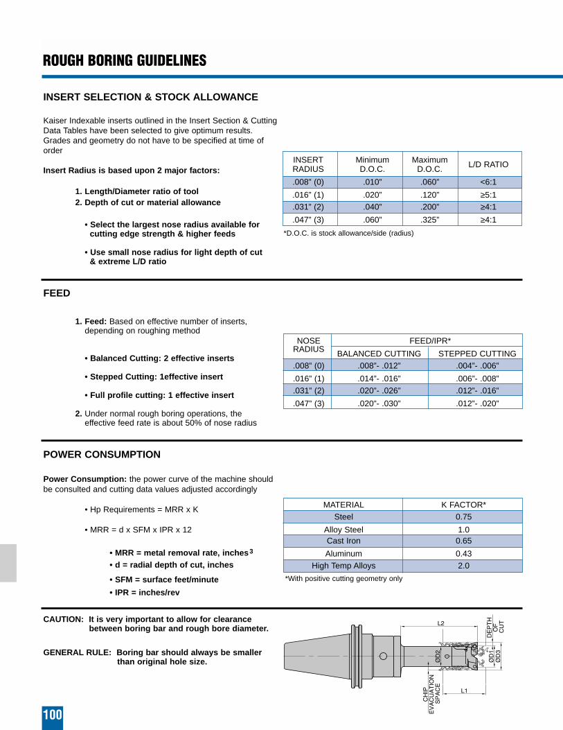
ROUGH BORING GUIDELINES
INSERT SELECTION & STOCK ALLOWANCE
Kaiser Indexable inserts outlined in the Insert Section & CuttingData Tables have been selected to give optimum results.Grades and geometry do not have to be specified at time oforder
Insert Radius is based upon 2 major factors:
1. Length/Diameter ratio of tool2. Depth of cut or material allowance
• Select the largest nose radius available for cutting edge strength & higher feeds
• Use small nose radius for light depth of cut & extreme L/D ratio
FEED
1. Feed: Based on effective number of inserts, depending on roughing method
• Balanced Cutting: 2 effective inserts
• Stepped Cutting: 1effective insert
• Full profile cutting: 1 effective insert
2. Under normal rough boring operations, the effective feed rate is about 50% of nose radius
POWER CONSUMPTION
Power Consumption: the power curve of the machine shouldbe consulted and cutting data values adjusted accordingly
• Hp Requirements = MRR x K
• MRR = d x SFM x IPR x 12
• MRR = metal removal rate, inches3
• d = radial depth of cut, inches
• SFM = surface feet/minute
• IPR = inches/rev
CAUTION: It is very important to allow for clearance between boring bar and rough bore diameter.
GENERAL RULE: Boring bar should always be smaller than original hole size.
INSERT Minimum Maximum L/D RATIORADIUS D.O.C. D.O.C.
.008” (0) .010” .060” <6:1
.016” (1) .020” .120” ≥5:1
.031” (2) .040” .200” ≥4:1
.047” (3) .060” .325” ≥4:1
*D.O.C. is stock allowance/side (radius)
*With positive cutting geometry only
NOSE FEED/IPR*RADIUS BALANCED CUTTING STEPPED CUTTING.008” (0) .008”- .012” .004”- .006”
.016” (1) .014”- .016” .006”- .008”
.031” (2) .020”- .026” .012”- .016”
.047” (3) .020”- .030” .012”- .020”
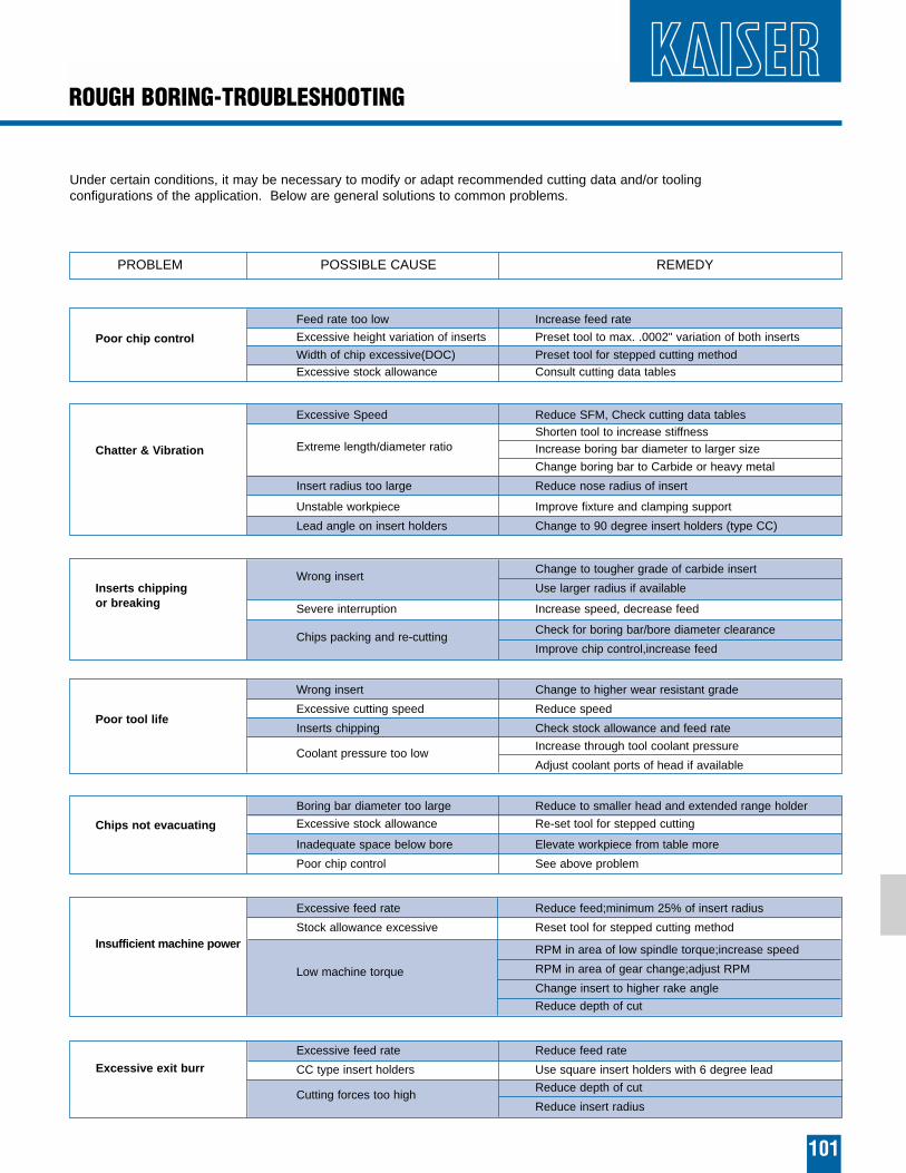
ROUGH BORING-TROUBLESHOOTING
101
Under certain conditions, it may be necessary to modify or adapt recommended cutting data and/or tooling configurations of the application. Below are general solutions to common problems.
PROBLEM POSSIBLE CAUSE REMEDY
Poor chip control
Feed rate too low Increase feed rate
Excessive height variation of inserts Preset tool to max. .0002" variation of both inserts
Width of chip excessive(DOC) Preset tool for stepped cutting methodExcessive stock allowance Consult cutting data tables
Chatter & Vibration
Excessive Speed Reduce SFM, Check cutting data tables
Extreme length/diameter ratioShorten tool to increase stiffnessIncrease boring bar diameter to larger size
Change boring bar to Carbide or heavy metal
Insert radius too large Reduce nose radius of insert
Unstable workpiece Improve fixture and clamping support
Lead angle on insert holders Change to 90 degree insert holders (type CC)
Inserts chipping Wrong insert
Change to tougher grade of carbide insert
or breakingUse larger radius if available
Severe interruption Increase speed, decrease feed
Chips packing and re-cuttingCheck for boring bar/bore diameter clearance
Improve chip control,increase feed
Poor tool life
Wrong insert Change to higher wear resistant grade
Excessive cutting speed Reduce speed
Inserts chipping Check stock allowance and feed rate
Coolant pressure too lowIncrease through tool coolant pressure
Adjust coolant ports of head if available
Chips not evacuating
Boring bar diameter too large Reduce to smaller head and extended range holder
Excessive stock allowance Re-set tool for stepped cutting
Inadequate space below bore Elevate workpiece from table more
Poor chip control See above problem
Insufficient machine power
Excessive feed rate Reduce feed;minimum 25% of insert radius
Stock allowance excessive Reset tool for stepped cutting method
Low machine torque
RPM in area of low spindle torque;increase speed
RPM in area of gear change;adjust RPM
Change insert to higher rake angle
Reduce depth of cut
Excessive exit burr
Excessive feed rate Reduce feed rate
CC type insert holders Use square insert holders with 6 degree lead
Cutting forces too highReduce depth of cut
Reduce insert radius