cutler-hammer i.b. 29c893b - · pdf filecutler-hammer instructions for ... 3-2.2 circuit...
TRANSCRIPT

I.B. 29C893B
Effective 2/01 Supersedes I.B. 29C893A dated July 1999
Cutler-Hammer
Instructions for Installation, Operation and Maintenance of Breaker Interface Module II
P R O T E C T I O N A N D C O O R D I N A T I O N
C O M M U N I C A T I O N S S Y S T E M S
E
N
E
R
G
Y
M
O
N
I
T
O
R
I
N
G
P
O
W
E
R
Q
U
A
L
I
T
Y

Effective 2/01
I.B. 29C893B Page iii
All possible contingencies which may arise during installation, operation or maintenance, and all details andvariations of this equipment do not purport to be covered by these instructions. If further information isdesired by purchaser regarding his particular installation, operation or maintenance of particular equipment,contact a Cutler-Hammer representative.
WARRANTY AND LIABILITY INFORMATION
NO WARRANTIES, EXPRESSED OR IMPLIED, INCLUDING WARRANTIES OF FITNESS FOR A PARTICULARPURPOSE OF MERCHANTABILITY, OR WARRANTIES ARISING FROM COURSE OF DEALING OR USAGE OFTRADE, ARE MADE REGARDING THE INFORMATION, RECOMMENDATIONS AND DESCRIPTIONS CON-TAINED HEREIN. In no event will Cutler-Hammer be responsible to the purchaser or user in contract, in tort (includ-ing negligence), strict liability or otherwise for any special, indirect, incidental or consequential damage or loss what-soever, including but not limited to damage or loss of use of equipment, plant or power system, cost of capital, loss ofpower, additional expenses in the use of existing power facilities, or claims against the purchaser or user by its cus-tomers resulting from the use of the information and descriptions contained herein.

Effective 2/01
I.B. 29C893BPage iv
TABLE OF CONTENTS
PageSECTION 1: INTRODUCTION
1-1 Common Terms...................................................................................................................................................11-2 Preliminary Comments and Safety Precautions..................................................................................................1
1-2.1 Safety Precautions .................................................................................................................................11-3 Product Overview ................................................................................................................................................21-4 Features and Functions.......................................................................................................................................2
SECTION 2: HARDWARE DESCRIPTION
2-1 General ...............................................................................................................................................................42-2 Operator Panel ....................................................................................................................................................42-3 Rear Access Area ...............................................................................................................................................5
2-3.1 DIP Switches ..........................................................................................................................................52-3.2 Sub-Network Connector .........................................................................................................................62-3.3 PONI Interface Connector (Network) .....................................................................................................62-3.4 Left Rear Chassis...................................................................................................................................72-3.5 Right Rear Chassis ................................................................................................................................7
2-4 Power Supplies ...................................................................................................................................................72-4.1 Switchboard Mounted Power Supply .....................................................................................................72-4.2 Breaker Interface Module Mounted Power Supply.................................................................................7
2-5 Communication Module (PONI) ..........................................................................................................................82-6 Specification Summary........................................................................................................................................8
SECTION 3: OPERATOR PANEL
3-1 General ...............................................................................................................................................................93-2 LEDs....................................................................................................................................................................9
3-2.1 Operational Condition LEDs...................................................................................................................93-2.2 Circuit Breaker Status LEDs.................................................................................................................103-2.3 Protection Status LEDs ........................................................................................................................103-2.4 Energy Monitoring LEDs ......................................................................................................................11
3-3 Display Windows ...............................................................................................................................................113-3.1 Identification Display ............................................................................................................................113-3.2 Description Display...............................................................................................................................123-3.3 Function Display...................................................................................................................................12
3-4 Pushbuttons ......................................................................................................................................................123-4.1 Raise and Lower Pushbuttons .............................................................................................................123-4.2 Up and Down Pushbuttons...................................................................................................................123-4.3 Help Pushbutton...................................................................................................................................133-4.4 Escape Pushbutton ..............................................................................................................................133-4.5 Select Pushbutton ................................................................................................................................133-4.6 Next Pushbutton...................................................................................................................................133-4.7 Select/Next Pushbutton Combination...................................................................................................13
3-5 Mimic Time-Current Curve ................................................................................................................................14

Effective 2/01
I.B. 29C893B Page v
PageSECTION 4: OPERATION
4-1 General .............................................................................................................................................................154-2 Security Password.............................................................................................................................................15
4-2.1 Change Security Password ..................................................................................................................154-3 Power Application..............................................................................................................................................18
4-3.1 Run Mode.............................................................................................................................................184-3.2 Learn Mode ..........................................................................................................................................18
4-4 Configure...........................................................................................................................................................194-4.1 Setting Date and Time..........................................................................................................................204-4.2 Updating for Added Devices.................................................................................................................204-4.3 Change Device Descriptions ................................................................................................................214-4.4 Change Group Descriptions .................................................................................................................214-4.5 Change Energy Synchronization Mode................................................................................................224-4.6 Assign the Peak Exeeded Output ........................................................................................................234-4.7 Assign the WH Pulse Initiator Output ...................................................................................................234-4.8 Program Settings Menu........................................................................................................................244-4.9 Program Groups Menu.........................................................................................................................264-4.10 Alarms Menu ........................................................................................................................................27
4-5 Displayed Information........................................................................................................................................284-6 Communications................................................................................................................................................28
4-6.1 Sub-Network Communications.............................................................................................................284-6.2 Main Network Communications............................................................................................................30
4-7 Test Trip Units ...................................................................................................................................................30
SECTION 5: INSTALLATION, STARTUP AND TESTING
5-1 Introduction........................................................................................................................................................325-2 Panel Preparation..............................................................................................................................................32
5-2.1 Cutout ...................................................................................................................................................325-2.2 Mounting...............................................................................................................................................325-2.3 Miscellaneous Mounting Details ...........................................................................................................32
5-3 Wiring ................................................................................................................................................................335-4 Initial Startup .....................................................................................................................................................33
5-4.1 Before Power Application .....................................................................................................................355-4.2 Initial Power Application .......................................................................................................................35
SECTION 6: TROUBLESHOOTING AND MAINTENANCE
6-1 Level of Repair ..................................................................................................................................................376-2 Troubleshooting.................................................................................................................................................376-3 Replacement .....................................................................................................................................................376-4 Maintenance and Care ......................................................................................................................................376-5 Return Procedure ..............................................................................................................................................376-6 Technical Assistance.........................................................................................................................................37
APPENDIX A: INSTRUCTIONAL REFERENCES .....................................................................................................40

Effective 2/01
I.B. 29C893BPage vi
LIST OF FIGURES
Figure Title Page
1-1 Breaker Interface Module in Service..........................................................................................................21-2 Typical System Configurations ..................................................................................................................3
2-1 Breaker Interface Module Operator Panel .................................................................................................42-2 Breaker Interface Module (Rear View) ......................................................................................................52-3 Breaker Interface Module (Rear Bottom View) ..........................................................................................62-4 Communications Module (PONI) - Shown Mounted..................................................................................62-5 Breaker Interface Module Terminal Block (Contacts 1-9)..........................................................................72-6 Breaker Interface Module Terminal Block (Contacts 10-18)......................................................................7
3-1 Operational and Circuit Breaker Status LEDs ...........................................................................................93-2 Protection Status and Energy Monitoring LEDs ........................................................................................93-3 Device Address Display...........................................................................................................................113-4 Group Display ..........................................................................................................................................113-5 Description and Function Displays ..........................................................................................................123-6 Main Menu Option Screens .....................................................................................................................123-7 Raise and Lower Pushbuttons.................................................................................................................133-8 Pushbuttons Near Function Display ........................................................................................................133-9 LED Type Mimic Time-Current Curve......................................................................................................14
4-1 Breaker Interface Module Menu Diagram................................................................................................164-2 Set Password Display..............................................................................................................................184-3 Learn Display...........................................................................................................................................184-4 Set Password Display..............................................................................................................................184-5 Typical Breaker Interface Module Displays .............................................................................................194-6 Typical Present Date Display...................................................................................................................204-7 Set Date Display......................................................................................................................................204-8 Set Device Description Display................................................................................................................214-9 Typical Existing Device Description Example..........................................................................................214-10 Typical New Device Description Example ...............................................................................................214-11 Set Group Description Display.................................................................................................................224-12 Set Sync Mode Display............................................................................................................................224-13 Typical Synchronization Mode Setting ....................................................................................................224-14 Typical Synchronization Time Setting......................................................................................................224-15 Set Peak Exceeded Display ....................................................................................................................234-16 Typical Peak Exceeded None Assignment..............................................................................................234-17 Typical Peak Exceeded Device Assignment ...........................................................................................234-18 Typical Peak Exceeded Group Assignment ............................................................................................234-19 Set WH Display........................................................................................................................................244-20 Typical WH Pulse Initiator None Assignment ..........................................................................................244-21 Typical WH Pulse Initiator Device Assignment........................................................................................244-22 Typical WH Pulse Initiator Group Assignment.........................................................................................244-23 Program Settings Display ........................................................................................................................254-24 Program Settings Configuration Submenu Display .................................................................................254-25 Program Settings Protection Submenu Display.......................................................................................254-26 Program Settings Device Alarm Submenu Display .................................................................................254-27 Program Settings BIM Alarm Submenu Display ......................................................................................25

Effective 2/01
I.B. 29C893B Page vii
Figure Title Page
4-28 Typical Frame Size Display .....................................................................................................................254-29 Program Groups Display .........................................................................................................................264-30 Maximum Peak Demand Display.............................................................................................................274-31 WH Pulse Initiator Display .......................................................................................................................274-32 No Alarms Display ...................................................................................................................................274-33 Alarms Menu Display...............................................................................................................................274-34 Typical Alarms Menu Display ..................................................................................................................284-35 Typical Meter Menu Display ....................................................................................................................304-36 “Address” Raise and Lower Pushbuttons ................................................................................................304-37 Test Display ............................................................................................................................................314-38 Phase Test Display .................................................................................................................................314-39 Trip Test Display......................................................................................................................................314-40 Typical Test Current Display....................................................................................................................314-41 Typical Test Time in Seconds Display.....................................................................................................314-42 Tripped Alarm Display .............................................................................................................................31
5-1 Cutout Dimensions and Drilling Pattern (inches) .....................................................................................325-2 Breaker Interface Module Dimensions (inches).......................................................................................335-3 Typical Network Wiring Diagram .............................................................................................................345-4 Connections and DIP Switch Rear Label Diagram..................................................................................35
LIST OF TABLES
Table Title Page
2.1 Breaker Interface Module Specifications ...................................................................................................8
4.1 Alarms Menu Messages ..........................................................................................................................29
5.1 Operational DIP Switch Settings..............................................................................................................36
6.1 Troubleshooting Guide ............................................................................................................................38
A.1 Instructional References..........................................................................................................................40


I.B. 29C893B Page 1
Effective 2/01
SECTION 1: INTRODUCTION
1-1 COMMON TERMS
Several commonly used terms or phrases are usedthroughout this manual. They are defined here to elimi-nate any confusion that might arise when reading thetext.
IMPACC (Integrated Monitoring, Protection andControl Communications) – A family of communicat-ing electrical power distribution protective devices,meters, motor control devices, communications net-works and protocols and software packages to providepower distribution monitoring and control.
INCOM (Industrial Communications) – A noiseimmune communications system designed specificallyfor power distribution monitoring and control applica-tions.
PONI (Product Operated Network Interface) – Aplug-in communications module that enables networkcommunications.
1-2 PRELIMINARY COMMENTS AND SAFETYPRECAUTIONS
This instructional manual is intended to present specificdescriptive, operational, installation and maintenanceinformation associated with the Breaker InterfaceModule only. The Breaker Interface Module is compati-ble with Digitrip OPTIM Trip Units, Digitrip RMS 810/910Trip Units, Magnum 1150 and 520MC Trip Units, IQEnergy Sentinels, Universal IQ Energy Sentinels and IQPower Sentinels. For a general overview of the entireDigitrip OPTIM Trip Unit System and certain specificapplication possibilities, refer to Instruction Book29C890 entitled “Instructional Overview for Use Of theDigitrip OPTIM Trip Unit System.”
Detailed instructional material relative to the installation,use and maintenance of specific devices is includedunder separate cover by a manual dedicated to eachdevice. A series of four manuals brings together thewide array of capabilities offered by the most advancedprogrammable trip unit system - Digitrip OPTIM. Referto Appendix A for all instruction material references.
Please read and understand this manual and all otherrelevant manuals before proceeding with the installation
and operation of any device included in the trip unit sys-tem. Pay particular attention to all WARNINGS andCAUTIONS. They are intended to help insure personnelsafety and equipment protection. Refer to the WARN-ING and CAUTION in Paragraph 1-2.1 before proceed-ing to any other section in this manual or any other man-ual. If further information is required by the purchaserregarding a particular installation, application or mainte-nance activity, a Cutler-Hammer representative shouldbe contacted.
1-2.1 SAFETY PRECAUTIONS
All safety codes, safety standards and/or regulationsmust be strictly observed in the installation, operationand maintenance of any device in this system.
THE WARNINGS AND CAUTIONS INCLUDED ASPART OF THE PROCEDURAL STEPS IN THIS DOCU-MENT ARE FOR PERSONNEL SAFETY AND PRO-TECTION OF EQUIPMENT FROM DAMAGE. ANEXAMPLE OF A TYPICAL WARNING LABEL HEAD-ING IS SHOWN ABOVE IN REVERSE TYPE TOFAMILIARIZE PERSONNEL WITH THE STYLE OFPRESENTATION. THIS WILL HELP TO INSURETHAT PERSONNEL ARE ALERT TO WARNINGS,WHICH MAY APPEAR THROUGHOUT THE DOCU-MENT. IN ADDITION, CAUTIONS ARE ALL UPPERCASE AND BOLDFACE AS SHOWN BELOW.
COMPLETELY READ AND UNDERSTAND THE MAT-ERIAL PRESENTED IN THIS DOCUMENT BEFOREATTEMPTING INSTALLATION, OPERATION ORAPPLICATION OF THE EQUIPMENT. IN ADDITION,ONLY QUALIFIED PERSONS SHOULD BE PERMIT-TED TO PERFORM ANY WORK ASSOCIATED WITHTHE EQUIPMENT. ANY WIRING INSTRUCTIONSPRESENTED IN THIS DOCUMENT MUST BE FOL-LOWED PRECISELY. FAILURE TO DO SO COULDCAUSE PERMANENT EQUIPMENT DAMAGE.
! WARNING
! CAUTION
Effective 2/01
I.B. 29C893BPage 2
1-3 PRODUCT OVERVIEW
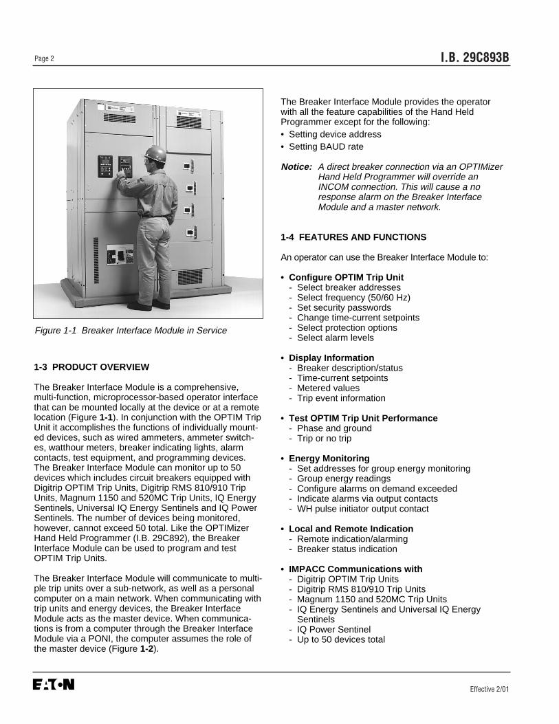
The Breaker Interface Module is a comprehensive,multi-function, microprocessor-based operator interfacethat can be mounted locally at the device or at a remotelocation (Figure 1-1). In conjunction with the OPTIM TripUnit it accomplishes the functions of individually mount-ed devices, such as wired ammeters, ammeter switch-es, watthour meters, breaker indicating lights, alarmcontacts, test equipment, and programming devices.The Breaker Interface Module can monitor up to 50devices which includes circuit breakers equipped withDigitrip OPTIM Trip Units, Digitrip RMS 810/910 TripUnits, Magnum 1150 and 520MC Trip Units, IQ EnergySentinels, Universal IQ Energy Sentinels and IQ PowerSentinels. The number of devices being monitored,however, cannot exceed 50 total. Like the OPTIMizerHand Held Programmer (I.B. 29C892), the BreakerInterface Module can be used to program and testOPTIM Trip Units.
The Breaker Interface Module will communicate to multi-ple trip units over a sub-network, as well as a personalcomputer on a main network. When communicating withtrip units and energy devices, the Breaker InterfaceModule acts as the master device. When communica-tions is from a computer through the Breaker InterfaceModule via a PONI, the computer assumes the role ofthe master device (Figure 1-2).
The Breaker Interface Module provides the operatorwith all the feature capabilities of the Hand HeldProgrammer except for the following:• Setting device address• Setting BAUD rate
Notice: A direct breaker connection via an OPTIMizerHand Held Programmer will override anINCOM connection. This will cause a noresponse alarm on the Breaker InterfaceModule and a master network.
1-4 FEATURES AND FUNCTIONS
An operator can use the Breaker Interface Module to:
• Configure OPTIM Trip Unit- Select breaker addresses- Select frequency (50/60 Hz)- Set security passwords- Change time-current setpoints- Select protection options- Select alarm levels
• Display Information- Breaker description/status- Time-current setpoints- Metered values- Trip event information
• Test OPTIM Trip Unit Performance- Phase and ground- Trip or no trip
• Energy Monitoring- Set addresses for group energy monitoring- Group energy readings- Configure alarms on demand exceeded- Indicate alarms via output contacts- WH pulse initiator output contact
• Local and Remote Indication- Remote indication/alarming- Breaker status indication
• IMPACC Communications with- Digitrip OPTIM Trip Units- Digitrip RMS 810/910 Trip Units- Magnum 1150 and 520MC Trip Units- IQ Energy Sentinels and Universal IQ Energy
Sentinels- IQ Power Sentinel - Up to 50 devices total
Figure 1-1 Breaker Interface Module in Service

Effective 2/01
I.B. 29C893B Page 3
Figure 1-2 Typical System Configurations
MasterComputer
BreakerInterfaceModule
ShieldedTwistedPair
SPBCircuit Breaker
with OPTIM
DSIICircuitBreaker
withOPTIM
Series CR-Frame
MCCBwith
OPTIM
To Other IMPACCCompatible Devices
PONI
OPTIMizer
Series CN-Frame
MCCBwith
OPTIM
Series CL-FrameMCCBwith
OPTIM
Circuit Breaker
with RMS 810
or 910
Series CF-FrameMCCB
ES
IQ Energy Sentinel
ShieldedTwistedPair
PONI Module(Required for IMPACC
Network Communicationsto Master Computer)
ShieldedTwisted
Pair
➁ ➂
➃
OPTIMizer ➀➀ OPTIMizer ➀
OPTIMizer ➀OPTIMizer ➀
Series CK-Frame
MCCBwith
OPTIM
OPTIMizer ➀
NOTES
➀ OPTIMizer Hand HeldProgrammer compatible onlywith OPTIM Trip Units
➁ Can monitor up to 50 com-patible devices.
➂ Circuit breakers with OPTIMTrip Units can be directlyconnected to a master com-puter, and do not have to beconnected through the BIM.
➃ Universal IQ Energy Sentinelalso compatible with BreakerInterface Module.
CONFIGURATIONS 1 + 2
Network Configuration —Breaker Interface Module withMaster Computer as MasterDevice
CONFIGURATION 1
Sub-Network Configuration —Breaker Interface ModuleFunctioning as Master Device
CONFIGURATION 2
Master Computer and IMPACCSoftware

I.B. 29C893BPage 4
Effective 2/01
SECTION 2: HARDWARE DESCRIPTION
2-1 GENERAL
The purpose of this section is to familiarize the readerwith the Breaker Interface Module hardware, nomencla-ture, and list the device’s specifications. The informationpresented is divided into the following four parts:• Operator Panel• Rear Access Area• External Hardware• Specification Summary
THIS IS A SOPHISTICATED PIECE OF ELECTRICALEQUIPMENT. AS SUCH, IT SHOULD BE HANDLED
CAREFULLY AT ALL TIMES TO AVOID POSSIBLEDEVICE DAMAGE.
2-2 OPERATOR PANEL
The operator panel, normally accessible from the out-side of a panel or door, provides a means for:• Being alerted to specific conditions• Receiving functional help• Programming• Parameter Monitoring/Selection
LEDs, Display Windows, Pushbuttons and a LED typeMimic Time-Current Curve make up the front accessibleoperator panel (Figure 2-1). Each item is discussed indetail in Section 3.
The eighteen LEDs on the operator panel will blink or belit continuously, depending on their specific function. All
Figure 2-1 Breaker Interface Module Operator Panel
1234
8765
Operational Condition LEDsCircuit Breaker Status LEDsProtection Status LEDsEnergy Monitoring LEDsDevice Identification DisplayDescription DisplayFunction DisplayGroup Identification DisplayRaise/Lower PushbuttonsUp/Down PushbuttonsHelp/Escape/Select/NextPushbuttonsMimic Time-Current CurveHigh Load LEDClear Alarm
1
2
3
4
9
7
6
8
10
11
12
910
11
1312
! CAUTION
14
13
14
5

I.B. 29C893B Page 5
Effective 7/99
the LEDs when lit are red, except for the OperationalLED which is green. LEDs are used to indicate a num-ber of functions, operations and/or warnings.
Four LED type display windows are used to display anarray of metered parameters, setpoints, messages andaddresses in a number of different formats. The infor-mation is presented in the form of display screens for avariety of categories.
The operator panel contains eight membrane pushbut-tons. Pushbuttons accomplish their function whenpressed and then released. Certain pushbuttons will,however, continue to scroll if they are pressed and notreleased.
2-3 REAR ACCESS AREA
The rear access area of the Breaker Interface Module isnormally accessible from the rear of an open panel door(Figure 2-2). All wiring connections and DIP switch set-tings are made at the rear of the chassis. For the sake
of uniform identification, the frame of reference whendiscussing the rear access area is facing the back of theBreaker Interface Module with the panel door open. Theterminal block providing alarm connections, for example,is located on the left side of the chassis.
2-3.1 DIP SWITCHES
A set of six DIP switches numbered 1 through 6 is locat-ed in the bottom left portion of the rear access area(Figure 2-3). Refer to Table 5.1 for exact switch settings.Their basic functions are as follows:
Switch 1: This switch puts the Breaker InterfaceModule in the Learn mode or the Run mode. DIP switch1 is only in the Learn mode (down position) for the fol-lowing instances:• When power is applied to the Breaker Interface
Module for the first time.• When the Update feature in the System display menu
is used to add new network devices.
Figure 2-2 Breaker Interface Module (Rear View)
1234
Dip Switches3-Pin Sub-Network ConnectorPONI Interface ConnectorCommunication Module (PONI)
1 2 3
4
7
65
567
Terminals 1-9Terminals 10-18Mouniting Position for BIMMounted Power Supply

I.B. 29C893BPage 6
Effective 2/01
In the down position, the Breaker Interface Module willsearch through the network for connected devices, learntheir addresses/ descriptions, and store the information innon-volatile memory. Once the learning or updatingprocesses have been completed, DIP switch 1 should bemoved to the “Run” (up) position.
Switches 2, 3, 4 and 5: These switches are not used.They are intended for possible future enhancementsand must be in the down position.
ONLY CONNECT OR DISCONNECT A COMMUNICA-TIONS MODULE (PONI) WITH DIP SWITCH 6 IN THE“OFF” (DOWN) POSITION. FAILURE TO DO SO CANCAUSE PERMANENT DAMAGE TO THE PONI.
Switch 6: This switch is referred to as a PONI powerswitch. The switch is in the “On” (up) position only whena communication module (PONI) is being used for net-work communications via IMPACC. It is in the “Off”(down) position when the Breaker Interface Module iscommunicating on a sub-network only, or when a PONIis being connected or disconnected.
2-3.2 SUB-NETWORK CONNECTOR
A three pin, male connector, located next to the DIPswitches, provides for a shielded twisted pair connectionpermitting the Breaker Interface Module to communicatewith up to 50 total trip units and energy monitoringdevices (Figure 2-3). The Breaker Interface Moduleassumes the role of the network master on a sub-net-work (Figure 1-2).
2-3.3 PONI INTERFACE CONNECTOR (NETWORK)
A port, located next to the sub-network connector, isprovided that will accept the D-sub male connector of anoptional and externally mounted communication module(PONI) (Figures 2-2, 2-3 and 2-4). The PONI providesfor a twisted pair connection permitting the BreakerInterface Module to communicate with a master comput-er (Paragraph 2-5).
Notice: A direct breaker connection via an OPTIMizerHand Held Programmer will override anINCOM connection. This will cause a noresponse alarm on the Breaker InterfaceModule and a master network.
Figure 2-3 Breaker Interface Module (Rear BottomView)
Figure 2-4 Communications Module (PONI) – ShownMounted
! CAUTION

I.B. 29C893B Page 7
Effective 2/01
2-3.4 LEFT REAR CHASSIS
A nine point terminal block, numbered 1 through 9, ismounted on the left rear chassis (Figures 2-5 and 5-4).Three sets of dry Form C output contacts are providedfor alarm connections. • Contacts 1, 2 and 3 — Remote Alarm• Contacts 4, 5 and 6 — High Load Alarm• Contacts 7, 8 and 9 — Peak Demand
Exceed Alarm
2-3.5 RIGHT REAR CHASSIS
A nine point terminal block, numbered 10 through 18 ismounted on the right rear chassis (Figures 2-6 and 5-4).• Contacts 10, 11 and 12 — Watt-hour Pulse
Initiator Output• Contacts 13 and 14 — Sync Pulse Input• Contact 15 — Not Used• Contacts 16, 17 and 18 — 24-30 Vdc Power/Ground
2-4 POWER SUPPLIES
Power for the Breaker Interface Module is supplied by aseparate external source mounted in the switchboard or
a power source mounted on the rear of the BreakerInterface Module at the factory. Refer to Table 2.1 foradditional power supply information and style/catalognumbers for the two Breaker Interface Module models.
2-4.1 SWITCHBOARD MOUNTED POWER SUPPLY
A switchboard mounted power supply is appropriate forSeries C L and N-Frame circuit breaker applications.Mount the selected power supply in the switchboard inaccordance with the manufacturer’s instructions. Itshould be a compatible 24-30 Vdc, 400 ma supply with aplus or minus 5% tolerance. The output of the separatelymounted power supplies specified in Table 2.1 are capa-ble of supplying power to any combination of 16 K-Frame, L-Frame and/or N-Frame circuit breakers andone Breaker Interface Module.
2-4.2 BREAKER INTERFACE MODULE MOUNTEDPOWER SUPPLY
A Breaker Interface Module mounted power supply isappropriate for Series C R-Frame, SPB Pow-R andDSII/DSLII circuit breaker applications. Circuit breakersof this type will supply power to the trip unit, and do notrequire an external power supply for this purpose. The
Figure 2-5 Breaker Interface Module Terminal Block(Contacts 1-9)
Figure 2-6 Breaker Interface Module Terminal Block(Contacts 10-18)

I.B. 29C893BPage 8
Effective 2/01
output of the power supply specified in Table 2.1 is capa-ble of supplying power to one Breaker Interface Moduleonly. The Breaker Interface Module mounted power sup-ply is supplied from the factory already mounted on therear of the Breaker Interface Module.
2-5 COMMUNICATION MODULE (PONI)
A PONI is required for communications between aBreaker Interface Module and a remote computer. Useof the PONI permits network communications with aremote computer functioning as the network master.The INCOM PONI, RS-232 PONI and PONI Modem can
all be used with the Breaker Interface Module. A PONIis not required for connection of a Breaker InterfaceModule on a sub-network.
Refer to the instruction material supplied with the PONIfor details. Refer to Section 4 for additional informationconcerning Breaker Interface Module communications.
2-6 SPECIFICATION SUMMARY
Refer to Table 2.1 for product specification details.
Table 2.1 Breaker Interface Module Specifications
Models/Control Power• BIM II with Switchboard Style No. 7801C61G03
Mounted Power Supply Catalog No. BIM II- BIM II Power Consumption 12 VA
• Switchboard Mounted (1) International Power SourcesPower Supplies 200 Butterfield Drive
Ashland, MA 01721(508) 881-7434PU200-16, 200W, 30 Vdc, Power SupplyPU110-16, 110W, 30 Vdc, Power Supply
(2) Farnell Advanced Power32111 Aurora RoadSolon, OH 44139(216) 349-0755NS075030/M 75W, 30 Vdc, Power SupplyNS055030/M 55W, 30 Vdc, Power Supply
• BIM II with Power ➀ Style 7801C61G04Supply Mounted Catalog No. BIMPS II- BIM II plus Supply 15 VA
Power Consumption- Input Voltage 100-240 Vac - Frequency 50-60 Hz
Relay Output Contacts• 10A Continuous @ 120/250 Vac Resistive Load• 10A Continuous @ 30 Vdc Resistive Load• 1/3 HP Continuous @ 250 Vac Inductive Load
Sync Pulse Inputs• Dry Contact• Pulse Width >5ms
Environment Conditions• Operating Temperature 0° to 70°C• Storage Temperature -30° to 85°C• Operating Humidity 0 to 95% Relative Humidity
(non-condensing)
Sub-network Communications• INCOM/IMPACC Compatible• Sub-network Address Range 1 to 32 (hexadecimal)• 1200 or 9600 Baud
Master Network Communications• INCOM/IMPACC Compatible via field installed communications module
(INCOM PONI, RS232 PONI, Modem PONI)• 1200 or 9600 Baud
➀ BIM mounted power supply is supplied from the factory already mounted on the BIM.
I.B. 29C893B Page 9
Effective 2/01
SECTION 3: OPERATOR PANEL
3-1 GENERAL
The operator panel, which is normally accessible fromthe outside of a panel or door, provides a means forbeing alerted to specific conditions, receiving functionalhelp, programming, and parameter monitoring/selection(Figure 2-1). For the purpose of familiarization, thepanel is divided into four sub-sections and discussedindividually:• LEDs• Display Windows• Pushbuttons• Mimic Time-Current Curve
NOTICE: In and Ir as used in any OPTIM Trip UnitSystem document are defined as follows:• In = Rating Plug Value• Ir = Long Delay Setting
3-2 LEDS
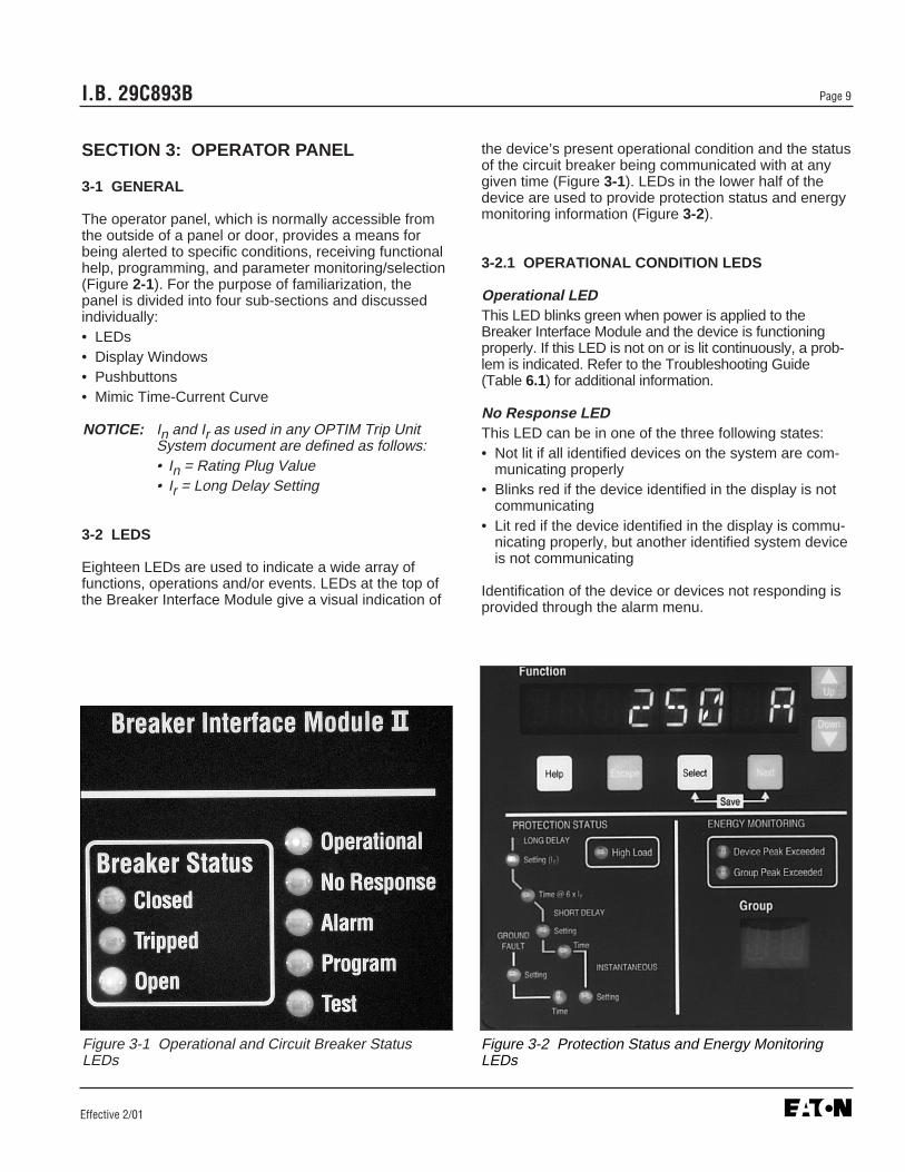
Eighteen LEDs are used to indicate a wide array offunctions, operations and/or events. LEDs at the top ofthe Breaker Interface Module give a visual indication of
the device’s present operational condition and the statusof the circuit breaker being communicated with at anygiven time (Figure 3-1). LEDs in the lower half of thedevice are used to provide protection status and energymonitoring information (Figure 3-2).
3-2.1 OPERATIONAL CONDITION LEDS
Operational LEDThis LED blinks green when power is applied to theBreaker Interface Module and the device is functioningproperly. If this LED is not on or is lit continuously, a prob-lem is indicated. Refer to the Troubleshooting Guide(Table 6.1) for additional information.
No Response LEDThis LED can be in one of the three following states:• Not lit if all identified devices on the system are com-
municating properly• Blinks red if the device identified in the display is not
communicating• Lit red if the device identified in the display is commu-
nicating properly, but another identified system deviceis not communicating
Identification of the device or devices not responding isprovided through the alarm menu.
Figure 3-1 Operational and Circuit Breaker StatusLEDs
Figure 3-2 Protection Status and Energy MonitoringLEDs

I.B. 29C893BPage 10
Effective 2/01
During the initial power application and with DIP switch1 in the “Learn Position” (Table 5.1 and Figure 5-4), theBreaker Interface Module is able to query the entire sys-tem, learn the address and description of all the deviceson the system, and store the information in memory.
Alarm LEDThis LED is lit red to indicate that an alarm has occurredwith respect to a device or devices known by the BreakerInterface Module to be on the system. Identification ofthe device or devices initiating the alarm is providedthrough the Alarms menu. The relay is energized whenthe LED is lit. If an alarm has not occurred, the LED isnot lit.
Program LEDThis LED is lit red to indicate that the Program modehas been selected for the device identified in theDescription Display or group identified in the GroupDisplay . It continues to be lit until the Program mode isexited.
Test LEDThis LED is lit red while a trip or no trip test is being per-formed. It indicates that the Test mode has been select-ed for the device identified in the Description Display .
3-2.2 CIRCUIT BREAKER STATUS LEDS
Closed LEDThis LED is lit red when the circuit breaker identified inthe Description Display is closed.
Tripped LEDThis LED is lit red when the circuit breaker identified inthe Description Display is automatically tripped as aresult of an overcurrent condition.
Open LEDThis LED is lit red when the circuit breaker identified inthe Description Display is opened as a result of:• Manual operation• Electrical operator• Shunt trip or undervoltage release• Communications command
High Load LEDThis LED can serve as an advance warning of a possibletrip condition. It is lit red when a selected level of loadcurrent for the circuit breaker identified in the Descrip-tion Display is reached or exceeded. The selected levelof load current is programmable from 50 to 100 percentof the long delay setting. It operates with an intentional
delay of 40 seconds to ride through momentary condi-tions to avoid nuisance alarms. Whenever the load cur-rent drops below the programmed level, the LED turnsoff. The LED blinks red when viewing or programmingthe high load setting for the identified circuit breaker.
3-2.3 PROTECTION STATUS LEDS
Long Delay Setting LEDThis LED is lit red if the circuit breaker identified in theDescription Display trips on long delay. If the circuitbreaker trips, the LED will remain lit until the trip unit islocally or remotely reset. The LED blinks red when view-ing or programming the long delay action or setting, orwhen a long delay pickup occurs for the identified circuitbreaker.
Long Delay Time LEDThis LED blinks red when viewing or programming thelong delay time setting or slope for the identified circuitbreaker.
Short Delay Setting LEDThis LED is lit red if the circuit breaker identified in theDescription Display trips on short delay. If the circuitbreaker trips, the LED remains lit until the trip unit islocally or remotely reset. The LED blinks red when view-ing or programming the short delay action or setting forthe identified circuit breaker.
Short Delay Time LEDThis LED blinks red when viewing or programming theshort delay time setting or slope for the identified circuitbreaker.
Instantaneous Setting LEDThis LED is lit red if the circuit breaker identified in theDescription Display trips on instantaneous. If the circuitbreaker trips, the LED remains lit until the trip unit is local-ly or remotely reset. The LED blinks red when viewing orprogramming the instantaneous action or setting for theidentified circuit breaker.
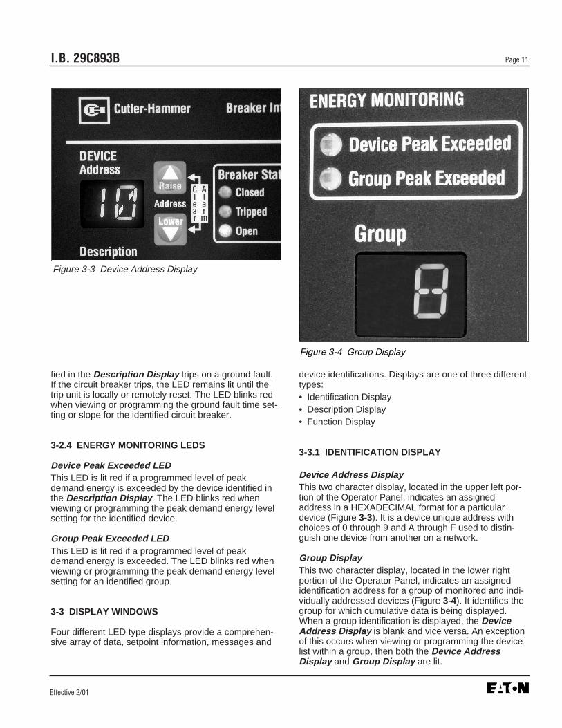
Ground Fault Setting LEDThis LED is lit red if the circuit breaker identified in theDescription Display trips on a ground fault. If the circuitbreaker trips, the LED will remain lit until the trip unit islocally or remotely reset. The LED blinks red when view-ing or programming the ground fault action or setting forthe identified circuit breaker. It is lit red during a groundalarm.
Ground Fault Time LEDThis LED is lit continuous red if the circuit breaker identi-
I.B. 29C893B Page 11
Effective 2/01
fied in the Description Display trips on a ground fault.If the circuit breaker trips, the LED remains lit until thetrip unit is locally or remotely reset. The LED blinks redwhen viewing or programming the ground fault time set-ting or slope for the identified circuit breaker.
3-2.4 ENERGY MONITORING LEDS
Device Peak Exceeded LEDThis LED is lit red if a programmed level of peakdemand energy is exceeded by the device identified inthe Description Display . The LED blinks red whenviewing or programming the peak demand energy levelsetting for the identified device.
Group Peak Exceeded LEDThis LED is lit red if a programmed level of peakdemand energy is exceeded. The LED blinks red whenviewing or programming the peak demand energy levelsetting for an identified group.
3-3 DISPLAY WINDOWS
Four different LED type displays provide a comprehen-sive array of data, setpoint information, messages and
device identifications. Displays are one of three differenttypes:• Identification Display• Description Display• Function Display
3-3.1 IDENTIFICATION DISPLAY
Device Address DisplayThis two character display, located in the upper left por-tion of the Operator Panel, indicates an assignedaddress in a HEXADECIMAL format for a particulardevice (Figure 3-3). It is a device unique address withchoices of 0 through 9 and A through F used to distin-guish one device from another on a network.
Group DisplayThis two character display, located in the lower rightportion of the Operator Panel, indicates an assignedidentification address for a group of monitored and indi-vidually addressed devices (Figure 3-4). It identifies thegroup for which cumulative data is being displayed.When a group identification is displayed, the DeviceAddress Display is blank and vice versa. An exceptionof this occurs when viewing or programming the devicelist within a group, then both the Device AddressDisplay and Group Display are lit.
Figure 3-3 Device Address Display
Figure 3-4 Group Display

I.B. 29C893BPage 12
Effective 2/01
3-3.2 DESCRIPTION DISPLAY
This eight character display, located just above theFunction Display , describes the device that is associat-ed with the address simultaneously displayed in theDevice Address Display (Figure 3-5). During the initiallearning process performed by the Breaker InterfaceModule, descriptions are automatically assigned todevices. The user can, however, establish new descrip-tions that are more relevant to a particular installation.This is accomplished through the use of the “DevDescription” feature of the System display menu. Inaddition, this display provides information required toperform grouping functions when in group relatedmenus.
3-3.3 FUNCTION DISPLAY
This eight character display, located just below theDescription Display, displays all the menu options, helpinformation and messages (Figure 3-5). Ten generalmenu option screens can be presented via the FunctionDisplay (Figure 3-6). Refer to Section 4 for specific detailsassociated with each menu option.
3-4 PUSHBUTTONS
The operator panel contains eight blue or white mem-brane pushbuttons. All pushbuttons accomplish their
function when pressed and then released. When appro-priate, the Raise, Lower, Up and Down pushbuttonswill continue to scroll if they are pressed and notreleased. Several operations, such as saving new infor-mation or deleting unwanted stored information,requires the simultaneous use of two different pushbut-tons and is specifically addressed in this section.
3-4.1 RAISE AND LOWER PUSHBUTTONS
The Raise and Lower pushbuttons, located next to theDevice Address Display, are used primarily to step upor down respectively through the assigned addresses ofconnected devices (Figure 3-7). The addresses willscroll continuously through the addresses if either push-button is held depressed. In addition, the two pushbut-tons perform similar functions on “Group” addresses dis-played in the Group Display when the Device AddressDisplay is blanked.
The Raise and Lower pushbuttons are also used todelete a stored alarm event displayed in the FunctionDisplay by pressing and releasing both pushbuttonssimultaneously.
3-4.2 UP AND DOWN PUSHBUTTONS
The Up and Down pushbuttons, located next to theFunction Display, are used to step up or down respec-
Figure 3-5 Description and Function Displays Figure 3-6 Main Menu Option Screens

I.B. 29C893B Page 13
Effective 2/01
tively through the menu option screens (Figure 3-8). Ifeither pushbutton is held depressed, the menu optionscreens will scroll continuously with a momentary pauseon each screen. Once a specific menu option screen isselected, each pushbutton can function in one of two dif-ferent ways:• Used to move from one selection to another within the
selected menu option• Used to change displayed programmed information or
establish a protective password
If, for example, the Meter menu is selected, each push-button will be used to move from selection to selectionwithin the Meter menu. If the Program Settings menuis selected, the two pushbuttons will be used to changea displayed programmed value to a new programmedvalue.
3-4.3 HELP PUSHBUTTON
When the Help pushbutton, located under the FunctionDisplay, is pressed and released with the BreakerInterface Module in any operational mode, an English lan-guage message scrolls across the Function Display(Figure 3-8). The messages relate to what is presentlybeing viewed in the Function Display and are intendedto assist the operator.
3-4.4 ESCAPE PUSHBUTTON
The Escape pushbutton, located under the FunctionDisplay, is used to move the Function Display back tothe top menu option screen one step at a time (Figure 3-8).
3-4.5 SELECT PUSHBUTTON
The Select pushbutton, located under the FunctionDisplay, is used to select the menu option displayed inthe Function Display or to enter a selected protectivepassword (Figure 3-8).
3-4.6 NEXT PUSHBUTTON
The Next pushbutton, located under the FunctionDisplay, is used in lieu of the Up and Down pushbut-tons to move from one selection to another within theselected menu option any time the Up and Down push-buttons are being used to make programmed informa-tion changes (Figure 3-8).
3-4.7 SELECT/NEXT PUSHBUTTON COMBINATION
The simultaneous use of the Select and Next pushbut-
Figure 3-7 Raise and Lower Pushbuttons Figure 3-8 Pushbuttons Near Function Display

Effective 2/01
I.B. 29C893BPage 14
tons, as indicated under the pushbuttons with a white tieline, accomplish the following:• Saves programmed settings• Initiates a test• Acknowledges an alarm and commits it to memory
3-5 MIMIC TIME-CURRENT CURVE
A LED type mimic time-current curve, located in thelower left portion of the operator panel under ProtectionStatus, is used to identify what specific portion, if any,of the identified circuit breaker’s characteristic curve isbeing affected by trip unit action or Breaker InterfaceModule operations (Figure 3-9). The LEDs operate asdescribed in paragraph 3-2.3 and provide critical infor-mation instantaneously after the automatic tripping of acircuit breaker. In addition, the mimic time-current curvesupplements the information displayed in the FunctionDisplay during the viewing or programming processes.
Figure 3-9 LED Type Mimic Time-Current Curve

I.B. 29C893B Page 15
Effective 2/01
SECTION 4: OPERATION
4-1 GENERAL
This section specifically describes the operation andfunctional use of the Breaker Interface Module. It is rec-ommended that the operator review the material pre-sented in Sections 2 and 3 prior to operating and usingthe Breaker Interface Module.
The Breaker Interface Module is a device used toaccess and program the capabilities of OPTIM 550,OPTIM 750, OPTIM 1050 and Magnum 1150 Trip Units.It can also be used to access only Digitrip RMS 810,Digitrip RMS 910 and Magnum 520MC Trip Units.Specific details associated with each individual trip unitare covered in separate instruction manuals for the dif-ferent trip units (Appendix A). Only the informationrequired to properly and effectively utilize the BreakerInterface Module is presented in this manual.
Insure that the Breaker Interface Module has been prop-erly installed and wired in keeping with the informationpresented in Section 5 before operating this device. Itfurther assumes that all the devices to be monitored areconnected and network and/or sub-network wiring is inplace.
A Breaker Interface Module menu diagram provides anoverall picture of this device’s capabilities and the orderin which the functional displays appear as the device isoperated (Figure 4-1). It is highly recommended that thismenu diagram be reviewed before proceeding with therest of this section. Such a review will greatly assist withthe initial understanding. In addition, the menu diagramprovides a good review for those already familiar withthe Breaker Interface Module.
Section 4 covers the operation and use of the BreakerInterface Module. It is broken down into six general cat-egories:• Security Password• Power Application• Configure Trip Units• Displayed Information• Communications• Test Trip Units
4-2 SECURITY PASSWORD
The Breaker Interface Module utilizes a password torestrict access to certain functional options. A validpassword is required to access the following main menuoptions or specific options within a particular main menuoption:
• Program Settings• Program Group• Test• System
Only - Set Date- Set Time- Update Devices- Set Device Description- Set Group Description- Set Password- Set Energy Synchronization Mode- Assign Peak Exceeded Output- Assign Watt-hour Pulse Initiator Output
The Breaker Interface Module is supplied with a factoryprogrammed password of 10000. If it is desirable toestablish a new password, follow the procedure outlinedin paragraph 4-2.1.
4-2.1 CHANGE SECURITY PASSWORD
Step 1: Use the Up or Down or Next pushbuttons tomove to the System main menu.
Step 2: Use the Select pushbutton to enter theSystem main menu.
Step 3: Continue using the Down pushbutton to moveto the Set Security Password display (Figure4-2).
Step 4: Press and release the Select pushbuttonagain. The display will ask for a protectivepassword. Use the Up or Down pushbuttonsto arrive at the present valid password. As pre-viously mentioned, the factory programmedpassword is 10000.
Step 5: Use the Select pushbutton to enter the validpassword. Once the password is accepted, thefar left character space in the password fieldbegins to blink, and the existing password con-tinues to be displayed. The blinking indicateswhich character is able to be changed. Thechoice of characters is a number from 0 to 9.
Step 6: Use the Up or Down pushbuttons to changeindividual characters and the Next pushbuttonto move from one character to another.
Step 7: When the displayed password is acceptable,press and release the Select and Next push-buttons simultaneously to enter the new pass-word into memory. The Function Display willreturn to Set Password .
Notice: It is strongly suggested that a record be madeof any new password and stored in a safeplace. If a new password is programmed and

Effective 2/01
I.B. 29C893BPage 16
Figure 4-1 Breaker Interface Module Menu Diagram — (continued to next page)
MAIN MENU
Configuration
Protection
Phase A Current
Phase B Current
Phase C Current
Ground Current
Neutral Current
Power
Peak Demand
Total Energy
Forward Energy
Reverse Energy
System Power Factor
Phase ATHD Magnitude
Phase BTHD Magnitude
Phase CTHD Magnitude
Phase A(%) Harmonic Content
Phase B(%) Harmonic Content
Phase C(%) Harmonic Content
➀ ➄
➁ ➁
➂
➂
➅
➅
➅
➅
➅
➁ ➃ ➁
Min Max Current
Voltage A-B
Voltage B-C
Voltage C-A
Voltage A-N
Voltage B-N
Voltage C-N
GroundTHD Magnitude
Ground(%) Harmonic Content
Neutral(%) Harmonic Content
Min A Current
Max A Current
Min B Current
Max BCurrent
Min C Current
Max C Current
MinGround Current
MaxGround Current
MinNeutralCurrent
MaxNeutralCurrent
Reset
➅
4 17
4
NeutralTHD Magnitude
19
Frame Size
Rating Plug
Long Delay Action
Long Delay Slope
Long Delay Setting
Long Delay Time
Powered Thermal Memory
Unpowered Thermal Memory
Short Delay Action
Short Delay Slope
Short Delay Setting
Short Delay Time
Instantaneous Action
Instantaneous Setting
Discriminator
Ground Fault Action
Ground Fault Slope
Ground Fault Setting
Ground Fault Time
Ground Current Sense
Ground Scale Factor
Breaker Neutral Ratio
Amp Out Of Balance Trip
Amp Out Of Balance Time
Phase Loss Trip Time
Undervoltage Trip Setting
Undervoltage Trip Time
Underfrequency Trip Pickup
Underfrequency Trip Time
Overfrequency Trip Pickup
Overfrequency Trip Time
Reverse Power Trip Action
Reverse Power Trip Time
Firmware Versions & Revisions
Number of Poles
Phase A Indicator
Frequency
Sentinel CT Ratio
Sentinel VAR Sign Convention
Sentinel Wiring Scheme
Waveform Acquisition Interval
Sliding Window Assignment
Pulse Initiation
➆/➇ ➉ 20
Device Alarms
BIM Alarm
No Response Enable
Memory Error Enable
Bad Frame Enable
Breaker Trip Enable
Long Delay Enable
Ground Overcurrent Enable
Neutral Overcurrent Enable
High Load Enable
Operations Enable
kVA Demand Enable
kW Demand Enable
Demand Peak Exceeded Setting
WH Pulse Initiator Setting
Power Factor Enable
THD Enable
Undervoltage Enable
Overvoltage Enable
Underfrequency Enable
Overfrequency Enable
Reverse Phase Sequence Enable
Fundamental thru 27 Harmonics
Fundamental thru 27 Harmonics
Fundamental thru 27 Harmonics
Fundamental thru 27 Harmonics
Fundamental thru 27 Harmonics
Ground Setting
Neutral Setting
High Load Setting
High Load Time
Operations Setting
kVA Demand Setting
kW Demand Setting
Power Factor Setting
THD Setpoints
Log Enable
Undervoltage Setting
Undervoltage Time
Overvoltage Setting
Overvoltage Time
Underfrequency Pickup
Underfrequency Time
Overfrequency Pickup
Overfrequency Time
Reverse Phase Sequence
METER HARMONICS VIEW SETTINGS PROGRAM SETTINGS
➆ ➉
13
1124
18
➉
➅
➅
➅
➅
➂
21
➆/➇ ➉ 20
➆/➇ ➉ 20
➆/➇ ➉ 20
➈
➈
28
28
28
28
Effective 2/01
I.B. 29C893B Page 17
No Alarms in System Memory
MAIN MENU
Device Address, DeviceDescription and Alarm
Message Details
or
Test Type(Phase/Ground)
Circuit Breaker Action(Trip/Non-Trip)
Test CurrentLevel
InitiateTest
CurrentDate
CurrentTime
Set Date
Set Time
Update (Learn NewNetwork Devices)
Set DeviceDescription
Set GroupDescription
Set Security Password
BIM Firmware Version and Revision
Demand SYNC Type and Time
Set Demand SYNC Type and Time
Peak Exceeded Assignment
Set Peak Exceeded Assignment
WH Pulse Assignment
Set WH Pulse Assignment
Message Displayed(Table 4.1)
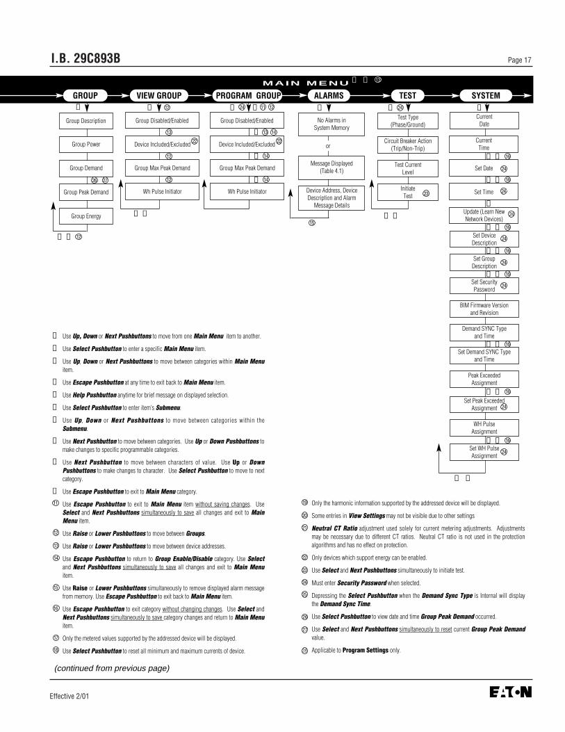
➀ Use Up, Down or Next Pushbuttons to move from one Main Menu item to another.
➁ Use Select Pushbutton to enter a specific Main Menu item.
➂ Use Up, Down or Next Pushbuttons to move between categories within Main Menuitem.
➃ Use Escape Pushbutton at any time to exit back to Main Menu item.
➄ Use Help Pushbutton anytime for brief message on displayed selection.
➅ Use Select Pushbutton to enter item’s Submenu.
➆ Use Up, Down or Next Pushbuttons to move between categories within theSubmenu.
➇ Use Next Pushbutton to move between categories. Use Up or Down Pushbuttons tomake changes to specific programmable categories.
➈ Use Next Pushbutton to move between characters of value. Use Up or DownPushbuttons to make changes to character. Use Select Pushbutton to move to nextcategory.
➉ Use Escape Pushbutton to exit to Main Menu category.
Use Escape Pushbutton to exit to Main Menu item without saving changes. UseSelect and Next Pushbuttons simultaneously to save all changes and exit to MainMenu item.
Use Raise or Lower Pushbuttons to move between Groups.
Use Raise or Lower Pushbuttons to move between device addresses.
Use Escape Pushbutton to return to Group Enable/Disable category. Use Selectand Next Pushbuttons simultaneously to save all changes and exit to Main Menuitem.
Use Raise or Lower Pushbuttons simultaneously to remove displayed alarm messagefrom memory. Use Escape Pushbutton to exit back to Main Menu item.
Use Escape Pushbutton to exit category without changing changes. Use Select andNext Pushbuttons simultaneously to save category changes and return to Main Menuitem.
Only the metered values supported by the addressed device will be displayed.
Use Select Pushbutton to reset all minimum and maximum currents of device.
Only the harmonic information supported by the addressed device will be displayed.
Some entries in View Settings may not be visible due to other settings
Neutral CT Ratio adjustment used solely for current metering adjustments. Adjustmentsmay be necessary due to different CT ratios. Neutral CT ratio is not used in the protectionalgorithms and has no effect on protection.
Only devices which support energy can be enabled.
Use Select and Next Pushbuttons simultaneously to initiate test.
Must enter Security Password when selected.
Depressing the Select Pushbutton when the Demand Sync Type is Internal will displaythe Demand Sync Time.
26 Use Select Pushbutton to view date and time Group Peak Demand occurred.
27 Use Select and Next Pushbuttons simultaneously to reset current Group Peak Demandvalue.
28 Applicable to Program Settings only.
➁
➃ ➇
➁
➂ ➃
(continued from previous page)
11
12
Group Description
Group Power
Group Demand
Group Peak Demand
Group Energy
➁
Group Disabled/Enabled
Device Included/Excluded
Group Max Peak Demand
Wh Pulse Initiator
Group Disabled/Enabled
Device Included/Excluded
Group Max Peak Demand
Wh Pulse Initiator
24
18
19
20
21
22
23
24
25
16
13
14
15
17
GROUP VIEW GROUP PROGRAM GROUP ALARMS TEST SYSTEM
➀ ➄ 13
➂ ➃ 12
➂ ➃
12
12
12
22 22
13
➁
15
23
24
24
24
24
➅ ➈ 16
➅ ➈ 16
➅ ➈ 16
➅ ➈ 16
➅ ➇ 16
➅ ➈ 16
➅ ➈ 16
➁ ➇
➇
➈
➈
11 1224
13 14
14
14
➁
24
24
24
➅ ➈ 16
24
➅
26 27

I.B. 29C893BPage 18
Effective 2/01
forgotten or lost at a later date, the BreakerInterface Module will have to be repro-grammed by Cutler-Hammer. Contact theAdvanced Product Support Center at 1-800-542-7883 for assistance.
4-3 POWER APPLICATION
Notice: Prior to applying power to the BreakerInterface Module, be certain that all DIPswitches are correctly set as described inParagraph 2-3.1 and Table 5.1. Of special sig-nificance are the Learn and Run modes asestablished by the position of DIP Switch 1.Device addresses and descriptions must belearned if this is the first time power is beingapplied to the Breaker Interface Module or isbeing updated because new devices havebeen added to an existing system.
When applying power to the Breaker Interface Module, itis important to know whether or not this is the initialapplication of power to the device. If this is not the initialpower application and no new devices have been addedto the system, power can be applied without any furtheractions. The Breaker Interface Module, having beenpreviously configured, will immediately begin to functionas intended. The Operational LED will blink green, adevice address and description will be displayed, andMeter will appear in the Function Display .
If this is the first time power is being applied to theBreaker Interface Module or new devices have beenadded to an existing system, additional steps must betaken to insure that the Breaker Interface Module func-tions properly. These steps follow under the headingsRun mode and Learn mode.
4-3.1 RUN MODE
The Breaker Interface Module should always be in theRun mode except for the instances described in thenext section under Learn mode. The Run mode isdetermined by the position of DIP switch 1, which is theup position for the Run mode.
4-3.2 LEARN MODE
If this is the first time for power application to theBreaker Interface Module, steps 1 through 7 should befollowed to insure that the Breaker Interface Module hasall the correct device addresses and descriptions inmemory:
Step 1: Make certain that all DIP switches are in thecorrect position and apply power to theBreaker Interface Module. The OperationalLED will blink green and Cutler-Hammer willbe momentarily displayed.
Step 2: The word Learn followed by a question mark(?) will appear in the Function Display(Figure 4-3). Press and release the Selectpushbutton to make the Breaker InterfaceModule begin the learning process.
Step 3: The next display will ask for the entry of a validpassword (Figure 4-4). Keep in mind that thefactory programmed password is 10000.
Step 4: The far left character of the five characterpassword, zero in this instance, will be blink-ing. The blinking indicates which digit is avail-able for change. Use the Up pushbutton tochange the zero to one. The valid password of10000 is now displayed.
Step 5: Press and release the Select pushbutton toenter the displayed password. Upon entry of avalid password, the word Learning beginsblinking in the Function Display . This indi-cates the Breaker Interface Module is pollingthe system for the address and description ofall connected devices. At the same time,
Figure 4-3 Learn Display
Figure 4-4 Set Password Display
Figure 4-2 Set Password Display

I.B. 29C893B Page 19
Effective 2/01
device addresses will appear in the DeviceAddress Display .
Step 6: When the learning process is complete, thelowest device address will appear in theDevice Address Display, the device descrip-tion will appear in the Description Display,and Meter will appear in the Function Display(Figure 4-5).
Step 7: The learning process is now complete and DIPswitch 1 should be moved to the up position(Run mode). The switch remains in this posi-tion until new devices are added to the sys-tem.
If this is not the first time for power application to theBreaker Interface Module but address and descriptionupdating must be performed because new devices havebeen added to the system, steps 1 and 2 should be fol-lowed:
Step 1: Set DIP switch 1 to the Learn mode (downposition).
Step 2: Use the Update feature of the System displaymenu to add the new addresses and descrip-tions without losing previously stored addressesand descriptions. Refer to Paragraph 4-4.2 forspecific instructions.
Notice: If the user prefers to have device descriptionsother than those automatically assigned duringthe Learn mode, use of the Set Device
Description feature of the System displaymenu permits this change. Refer to Paragraph4-4.3 for additional setup information.
4-4 CONFIGURE
Notice: The OPTIMizer Hand Held Programmer shouldbe used to establish unique device addressesand the Baud Rate before configuring the tripunit. Refer to Instruction Book 29C892 cover-ing the OPTIMizer Hand Held Programmer fordetails.
The Breaker Interface Module is used to establish spe-cific system functions and program protective, coordina-tion and alarm features.
First check and set or perform, if required, the followingsystem functions found under the System menu:• Set Date• Set Time• Update Devices• Set Device Description• Set Group Description• Set Password• Set Energy Synchronization Mode• Assign Peak Exceeded Output• Assign Watt-Hour Pulse Initiator Output
Once system functions are established, the protective,coordination and alarm features are programmed asrequired. The general features to be programmed are:• Time-current setpoints• Protection options• Alarm levels
Trip unit configuration and/or the configuration of groupsof devices take place within two different menus:• Program Settings• Program Groups
The Breaker Interface Module, as just outlined, permitsthe programming of individual trip units and groups ofindividual devices. The group programming capability isespecially helpful when the cumulative information of agroup of devices is required. It eliminates the need tocollect and record individually monitored values. Referto the Breaker Interface Module menu diagram (Figure4-1) to review all the programmable features included inthese menus.
The Programming associated with each menu isaddressed in this section to facilitate the programmingprocess. This information is not, however, intended tocover in detail all the available trip unit protective func-tions, settings and coordination possibilities. For specific
Figure 4-5 Typical Breaker Interface Module Displays

I.B. 29C893BPage 20
Effective 2/01
details on the capabilities of individual trip units, refer toInstruction Book 29C891 covering OPTIM Trip Units,and Instruction Book 70C1036 covering Magnum 1150Trip Units.
4-4.1 SETTING DATE AND TIME
The present date and time are displayed first under theSystem display menu. If, for any reason, the displayeddate and/or time must be altered, the programmable SetTime and Set Date features are available for this pur-pose. Procedural steps to accomplish these changesfollow:
Step 1: Use the Up or Down pushbuttons to move tothe System display menu.
Step 2: Use the Select pushbutton to enter theSystem display menu. The present date will bethe first display (Figure 4-6).
Step 3: Continue using the Down or Next pushbuttonto move to the Set Date display (Figure 4-7).
Step 4: To enter Set Date, press and release theSelect pushbutton. The display will ask for aprotective password. Use the Up or Downpushbuttons to arrive at a valid password. Aspreviously mentioned, the factory programmedpassword is 10000.
Step 5: Use the Select pushbutton to enter the validpassword. Once the password is accepted, thepresent date first viewed in Figure 4-6 will bedisplayed with the two character month blink-ing. The blinking indicates which charactersare able to be changed. Use the Up or Downpushbuttons to make the changes.
Step 6: Once any required change is made to themonth, use the Next pushbutton to move to theday and year for any necessary changes.
Step 7: When the displayed date is correct, press andrelease the Select and Next pushbuttonssimultaneously to enter the new date intomemory.
Step 8: Use the Down pushbutton to move to the SetTime display if a change in the time is required.To alter the present programmed time, the pro-cedure is the same as just described in the pre-vious steps for changing the date.
Step 9: Use the Escape pushbutton to return to theSystem display menu.
4-4.2 UPDATING FOR ADDED DEVICES
As outlined in Paragraph 2-3.1, DIP switch 1 in thedown position puts the Breaker Interface Module in theLearn mode. In this position, a newly installed BreakerInterface Module is capable of learning the addressesand descriptions of all system devices. If new devicesare added to an existing system at a future time, anUpdate feature is provided as part of the System dis-play menu to permit the learning of new device address-es and descriptions. Use of this feature will not onlylearn and store the new information, it protects alreadystored addresses and descriptions from any inadvertentchanges. To use the Update feature, refer to the follow-ing steps:
Step 1: Move DIP switch 1 to the down position (Learnmode).
Step 2: Use the Up or Down pushbuttons to move tothe System display menu.
Step 3: Use the Select pushbutton to enter theSystem display menu. The present date will bethe first display (Figure 4-6).
Step 4: Continue using the Down or Next pushbuttonsto move to the Update display. To enterUpdate, press and release the Select push-button. Learn ? will appear in the FunctionDisplay (Figure 4-3).
Step 5: Press and release the Select pushbutton again.The display will ask for a protective password.Use the Up or Down pushbuttons to arrive at avalid password. As previously mentioned, thefactory programmed password is 10000.
Figure 4-6 Typical Present Date Display Figure 4-7 Set Date Display

I.B. 29C893B Page 21
Effective 2/01
Step 6: Use the Select pushbutton to enter the validpassword. Once the password is accepted, theBreaker Interface Module begins the learningprocess as indicated by the blinking wordLearning in the Function Display .
Step 7: When the learning process is completed,System will again appear in the FunctionDisplay . If an already existing device is notfound while updating, the Device Address willdisplay a device with the Description Displayindicating No Resp. The operator will have theopportunity to Delete? the unit by pressing andreleasing the Select pushbutton. Pressing andreleasing the Next pushbutton will, however,maintain the unit within the Breaker InterfaceModule.
Step 8: Return DIP switch 1 to the up position (Runmode).
4-4.3 CHANGE DEVICE DESCRIPTIONS
If device descriptions automatically assigned during thelearning process are not meaningful enough for a partic-ular system, a Set Device Description feature is pro-vided as part of the System display menu to permitchanging existing device descriptions to new descrip-tions. Proceed with the following steps to make anydesired changes:
Step 1: Check to be certain that the address appearingin the Device Address Display is the addressof the device requiring a description change.
Step 2: Use the Up or Down pushbuttons to move tothe System display menu.
Step 3: Use the Select pushbutton to enter theSystem display menu.
Step 4: Continue using the Down or Next pushbuttonsto move to the Set Device Description display(Figure 4-8).
Step 5: Press and release the Select pushbuttonagain. The display will ask for a protectivepassword. Use the Up or Down pushbuttons toarrive at a valid password. As previously men-tioned, the factory programmed password is10000.
Step 6: Use the Select pushbutton to enter the validpassword. Once the password is accepted, thefar left character in the Description Displaybegins blinking (Figure 4-9). The blinking indi-
cates which character is able to be changed.The description can be up to 8 characters inlength. The choice of characters can be ablank space, *, +, -, /, ?, a number from 0 to 9,or a letter from A to Z.
Step 7: Use the Up or Down pushbuttons to changeindividual characters and the Next pushbuttonto move from one character to another.
Step 8: When the displayed description is acceptable,press and release the Select and Next push-buttons simultaneously to enter the newdescription into memory. Note that the newdescription appears in the DescriptionDisplay (Figure 4-10) and Set DeviceDescription again appears in the FunctionDisplay (Figure 4-8).
4-4.4 CHANGE GROUP DESCRIPTIONS
If the group descriptions automatically assigned by theBreaker Interface Module are not meaningful enough fora particular system, a Set Group Description feature isprovided as part of the System display menu to permitchanging existing group descriptions to new descrip-tions. Proceed with the following steps to make anydesired changes:
Step 1: Use the Up or Down pushbuttons to move to the System display menu.
Figure 4-8 Set Device Description Display
Figure 4-10 Typical New Device DescriptionExample
Figure 4-9 Typical Existing Device DescriptionExample

I.B. 29C893BPage 22
Effective 2/01
Step 2: Use the Select pushbutton to enter the Systemdisplay menu.
Step 3: Continue using the Down or Next pushbuttons to move to the Set Group Description display (Figure 4-11).
Step 4: Press and release the Select pushbutton again.The display will ask for a protective password. Use the Up or Down pushbuttons to arrive at a valid password. As previously mentioned, the factory programmed password is 10000.
Step 5: Use the Select pushbutton to enter the valid password. Once the password is accepted, the Function Display will indicate Group 01 . Use the Select pushbutton to select which group, 1 through 8, is to be assigned.
Step 6: When the Group Description is entered, the far left character in the Description Display also begins blinking. The blinking indicates which character is able to be changed. The description can be up to 8 characters in length. The choice of characters can be a blank space, *, +, -, ?, a number from 0 to 9, or a letter from A to Z.
Step 7: Use the Up or Down pushbuttons to change individual characters and the Next pushbutton to move from one character to another.
Step 8: When the displayed description is acceptable, press and release the Select and Next push-buttons simultaneously to enter the new group description into memory. The Breaker InterfaceModule returns to displaying the device in the Description Display and Set Group Description again appears in the Function Display .
4-4.5 CHANGE ENERGY SYNCHRONIZATION MODE
The energy synchronization mode may be assignedusing the Set Sync Mode feature provided as part ofthe System display menu. Proceed with the followingsteps to make any desired changes:
Step 1: Use the Up or Down pushbuttons to move to the System display menu.
Step 2: Use the Select pushbutton to enter the Systemdisplay menu.
Step 3: Continue using the Down or Next pushbuttons to move to the Set Sync Mode display (Figure 4-12).
Step 4: Press and release the Select pushbutton again.The display will ask for a protective password. Use the Up or Down pushbuttons to arrive at a valid password. As previously mentioned, the factory programmed password is 10000.
Step 5: Use the Select pushbutton to enter the valid password. Once the password is accepted, the current synchronization mode setting will be dis-played (Figure 4-13).
Step 6: Use the Up or Down pushbuttons to change thesetting.
Step 7: Use the Next pushbutton to advance to the synchronization time setting (Figure 4-14).
Step 8: Use the Up or Down pushbuttons to change thetime (1-60 minutes). The Next pushbutton will cycle back to the synchronization mode setting.
Step 9: When the synchronization mode settings are acceptable, press and release the Select and Next pushbuttons simultaneously to enter the new settings into memory. The Set Sync Modedisplay again appears in the Function Display(Figure 4-12).
Figure 4-11 Set Group Description Display
Figure 4-12 Set Sync Mode Display
Figure 4-13 Typical Synchronization Mode Setting
Figure 4-14 Typical Synchronization Time Setting

I.B. 29C893B Page 23
Effective 2/01
4-4.6 ASSIGN THE PEAK EXCEEDED OUTPUT
The peak exceeded relay output may be assigned toNONE, one of the 50 devices or one of the 8 groups.This is accomplished using the Set Peak Exceededfeature provided as part of the System display menu.Proceed with the following steps to make any desiredchanges:
Step 1: Use the Up or Down pushbuttons to move to the System display menu.
Step 2: Use the Select pushbutton to enter the Systemdisplay menu.
Step 3: Continue using the Down or Next pushbuttons to move to the Set Peak Exceeded display (Figure 4-15).
Step 4: Press and release the Select pushbutton again.The display will ask for a protective password. Use the Up or Down pushbuttons to arrive at a valid password. As previously mentioned, the factory programmed password is 10000.
Step 5: Use the Select pushbutton to enter the valid password. Once the password is accepted, the current watt-hour pulse initiator output setting will be displayed (Figures 4-16, 4-17 or 4-18).
Step 6: Use the Up or Down or Next pushbuttons to change the setting.
Step 7: When the peak exceeded output setting is acceptable, press and release the Select and Next pushbuttons simultaneously to enter the new settings into memory. The Set Peak Exceeded display again appears in the Function Display (Figure 4-15).
4-4.7 ASSIGN THE WH PULSE INITIATOR OUTPUT
The watt-hour pulse initiator relay output may beassigned to NONE, one of the 50 devices or one of the8 groups. This is accomplished using the Set WHPulse Initiator feature provided as part of the Systemdisplay menu. Proceed with the following steps to makeany desired changes:
Step 1: Use the Up or Down pushbuttons to move to the System display menu.
Step 2: Use the Select pushbutton to enter the Systemdisplay menu.
Step 3: Continue using the Down or Next pushbuttons to move to the Set WH Pulse Initiator display (Figure 4-19).
Step 4: Press and release the Select pushbutton again.The display will ask for a protective password. Use the Up or Down pushbuttons to arrive at a valid password. As previously mentioned, the factory programmed password is 10000.
Step 5: Use the Select pushbutton to enter the valid password. Once the password is accepted, the current watt-hour pulse initiator output setting will be displayed (Figures 4-20, 4-21 or 4-22).
Step 6: Use the Up or Down or Next pushbuttons to change the setting.
Step 7: When the watt-hour pulse initiator output settingis acceptable, press and release the Select andNext pushbuttons simultaneously to enter the new settings into memory. The Set WH Pulse Initiator display again appears in the Function Display (Figure 4-19).
Figure 4-15 Set Peak Exceeded Display
Figure 4-18 Typical Peak Exceeded Group Assignment
Figure 4-17 Typical Peak Exceeded Device Assignment
Figure 4-16 Typical Peak Exceeded None Assignment

Programmed settings can only be saved as a groupthrough the simultaneous use of the Select and Nextpushbuttons, not as individual settings.
In addition to using the Help pushbutton to define a par-ticular display during programming, it should be notedthat the LED type mimic time-current curve helps to fur-ther identify what is being viewed in the FunctionDisplay . When the long delay setting is being pro-grammed for example, the programmed setting value interms of the number of amperes only appears in the dis-play. The long delay setting LED, however, blinks toindicate the particular function.
Several of the settings included within the ProgramSettings menu are included for information purposesand are not programmable through the BreakerInterface Module. These settings will not change whenattempting to modify them. Examples are: • Device Firmware Version and Revision• Number of Poles• Circuit Breaker Frame Size• Rating Plug Size
These settings are automatically established duringcommunications between the Breaker Interface Moduleand the trip unit.
Any operator associated with programming will quicklydiscover that programming through the BreakerInterface Module is a matter of simple, repetitive steps:
Step 1: Check to be certain that the address anddescription being displayed are correct.
Step 2: Use the Up or Down pushbuttons to move tothe Program Settings display menu (Figure4-23).
I.B. 29C893BPage 24
Effective 2/01
4-4.8 PROGRAM SETTINGS MENU
Viewing already programmed settings without beingable to alter the settings is made possible by the ViewSettings menu. This menu is discussed in detail inParagraph 4-5 entitled “Displayed Information”. Theinformation displayed in the View Settings menu isestablished by the settings programmed here in theProgram Settings menu.
The View Settings and Program Settings menus aredivided into submenus based on functionality. Threepossible submenus (CONFIG, PROTECT andDEVALARM ) pertain to settings based at the selecteddevice. A submenu will be available only if the devicesupports at least one of the settings within the submenu.A fourth submenu (BIMALARM ) pertains to settingsresiding within the Breaker Interface Module that areassociated with the selected device.
Programming Reminders
Keep in mind that the setting possibilities shown in Figure 4-1 for the Program Settings menu are all of thepossibilities within the Digitrip Family of Trip Units. If aparticular trip unit does not support a particular feature,that feature will not be displayed as the operator movesthrough the menu.
The Program Settings menu is Password Protected.The operator must know a valid password to proceed.The factory programmed password is 10000. This mayhave been altered. Refer to Paragraph 4-2.
A trip unit will continue to provide protection in keepingwith its presently programmed settings until new set-tings are programmed, entered and accepted.
Figure 4-19 Set WH Display
Figure 4-22 Typical WH Pulse Initiator GroupAssignment
Figure 4-21 Typical WH Pulse Initiator DeviceAssignment
Figure 4-20 Typical WH Pulse Initiator None Assignment

I.B. 29C893B Page 25
Effective 2/01
Step 3: Use the Select pushbutton to enter theProgram Settings display menu. The displaywill ask for a security password. Use the Up orDown pushbuttons to arrive at a valid pass-word. As previously mentioned, the factoryprogrammed password is 10000.
Step 4: Use the Select pushbutton to enter the validpassword. Once the password is accepted,one of the following submenus will appear inthe Function Display: CONFIG , PROTECT,DEVALARM or BIMALARM (Figures 4-24,4-25, 4-26 or 4-27 respectively).
Step 5: Use the Next pushbutton to move from sub-menu to submenu (if more than one submenuis available for the selected device). Keep inmind that once a submenu is passed by, thereis no pushbutton that will move the displayback. If the operator wants to visit a submenualready passed in the display, it will requirecontinued forward scrolling.
Step 6: Use the Select pushbutton to enter therequired submenu. Once the submenu isentered, an appropriate setting will appear inthe Function Display as shown, for example,in Figure 4-28.
Step 7: Use the Next pushbutton to move from pro-grammable feature to programmable feature.Keep in mind that once a feature is passed by,there is no pushbutton that will move the dis-play back. If the operator wants to visit a set-ting already passed in the display, it will requirecontinued forward scrolling. A few setting val-ues require the Next pushbutton to scrollthrough the setting characters as described inStep 8. For these settings, Select pushbuttonwill be used to advance to the next setting.
Step 8: Use the Up or Down pushbuttons to movethrough all the possible choices within a particu-lar setting until the required setting is displayed.Holding the Up or Down pushbutton depressedwill scroll through the possible choices. Whenthe value contains a large number of settings,the speed of scrolling can increase rapidly. Fewnumerical settings may be changed on a char-acter basis. These settings will have their first
Figure 4-23 Program Settings Display
Figure 4-27 Program Settings BIM Alarm SubmenuDisplay
Figure 4-26 Program Settings Device AlarmSubmenu Display
Figure 4-25 Program Settings Protection SubmenuDisplay
Figure 4-24 Program Settings ConfigurationSubmenu Display
Figure 4-28 Typical Frame Size Display
character blinking when entered. Use the Upand Down pushbuttons to change the charac-ter between numbers 0 to 9. The Next pushbut-ton will advance to the next character. TheSelect pushbutton will advance to the next set-ting in the submenu.
Step 9: Once all the settings for the selected submenuare set as required, use the Escape pushbut-ton to exit the submenu. The FunctionDisplay will again appear with the submenudisplay. Note that use of the Escapepushbutton to exit a submenu will retain thesetting changes made for the submenu set-tings. Use of the Escape pushbutton at thesubmenu display will, however, exit the

I.B. 29C893BPage 26
Effective 2/01
Program Groups display menu. The display will ask for a security password. Use the Up orDown pushbuttons to arrive at a valid pass-word. As previously mentioned, the factory programmed password is 10000.
Step 3: Use the Select pushbutton to enter the valid password. Once the password is accepted, thefirst group's description will appear on the Description Display with the group number indicated on the Group Display.
Step 4: Use the Up or Down pushbutton to Enable or Disable a group. Use the Raise or Lowerpushbuttons to move between groups.
Step 5: Use the Next pushbutton to advance to the setting which allows the operator to include or exclude devices in the group. Once entered, the Device Address Display and DescriptionDisplay will indicate a particular device. Use the Raise or Lower pushbuttons to move fromone device to another. Use the Up or Downpushbuttons to include or exclude a device in a group. Only devices which support energy can be included in a group.
Step 6: Use the Next pushbutton to enter the Group Maximum Peak Demand setting (Figure 4-30). The far-left number in the Function Display begins blinking. The blinking indicateswhich number or character is to be changed. The numbers can range from 0 to 9. The seventh character is the scale factor of the demand unit, which could be K or M for Kilowatts or Megawatts respectively. The eighth character, W, is the non-programmable Watts units character.
Step 7: Use the Up or Down pushbuttons to change the individual numbers or the scale factor and the Next pushbutton to move from one num-ber or character to another.
Step 8: When the displayed number is acceptable, press the Select pushbutton to enter the WH Pulse Initiator setting (Figure 4-31). The far-left number in the Function Displaybegins blinking. The blinking indicates which
Program Settings function without retainingthe setting changes. Return to Step 5 to makechanges to the other submenu settings asrequired.
Step 10: Once all the settings are set as required, usethe Select and Next pushbuttons simultane-ously to save and establish the new settings.When the pushbuttons are pressed andreleased simultaneously, Wait appears in theFunction Display until the process is com-plete. Once complete, an Accepted orRejected message will be displayed. TheAccepted or Rejected message remains dis-played until cleared by the use of any pushbut-ton. Once cleared, the Program Settings dis-play appears.
4-4.9 PROGRAM GROUPS MENU
Viewing already programmed groups without being ableto alter the group settings is made possible by the ViewGroups menu. This menu is discussed in detail inParagraph 4-5 entitled “Displayed Information.” Theinformation displayed in the View Groups menu isestablished by settings programmed here in theProgram Groups menu.
The Program Groups menu will allow the user to defineup to 8 groups for energy monitoring purposes. Anyenergy monitoring device that is on the sub-network (i.e.OPTIM 1050, Digitrip 810/910, Magnum 1150, EnergySentinels or Power Sentinels) can be included in one ormore groups for the purpose of collective monitoring ofpower and energy parameters. The user can definethese 8 groups by selecting which group they will beworking with, then including or excluding each of theenergy monitoring devices.
After the groups are defined, the collective energy andpower can be viewed by the user upon entering theGroups Menu entry.
The Program Groups menu is Password Protected.The operator must know a valid password to proceed.The factory programmed password is 10000. This mayhave been altered. Refer to Paragraph 4-2.
Proceed with the following steps to program or makeany desired changes:
Step 1: Use the Up or Down pushbuttons to move to the Program Groups display (Figure 4-29).
Step 2: Use the Select pushbutton to enter the Figure 4-29 Program Groups Display

I.B. 29C893B Page 27
Effective 2/01
number or character is to be changed. The numbers can range from 0 to 9 and the sixth character is the scale factor of the energy unit,which could be K or M for Kilowatt-hours or Megawatt-hours respectively. The seventh or eighth characters, WH, are the non-program-mable watt-hours units characters
Step 9: Use the Up or Down pushbuttons to change the individual numbers or the scale factor and the Next pushbutton to move from one num-ber or character to another.
Step 10: When the displayed number is acceptable, press the Select pushbutton to return to the groups Enable or Disable menu (Step 4) to begin programming another group.
Step 11: When the settings entered are acceptable, press and release the Select and Next push-buttons simultaneously to enter the new set-tings in the memory. Note that ALL settings forALL groups are saved. The Escape pushbut-ton will abort all programming and return to theProgram Group display menu.
4-4.10 ALARMS MENU
When an alarm has occurred with respect to a device ordevices know by the Breaker Interface Module to be onthe system, the Alarm LED is lit red. At the same time,information relevant to the event is stored in memory.The Alarms menu provides a means for accessinginformation pertaining to a particular alarm or all of thealarms in memory. The Alarm LED remains lit until thestored information for all alarms is cleared.
Depending on the devices attached, a number of possi-ble “Alarm Messages” can appear in the FunctionDisplay while in the Alarms menu. The “AlarmMessage” blinks when displayed in the FunctionDisplay . Use of the Select pushbutton allows explana-
Figure 4-32 No Alarms Display
Figure 4-33 Alarms Menu Display
Figure 4-30 Maximum Peak Demand Display
Figure 4-31 WH Pulse Initiator Display
tory information associated with each “Alarm Message”to scroll across the Function Display . Refer to Table4.1 for current possible “Alarm Messages” and the spe-cific explanatory information provided for each message.
When the Alarms menu is accessed, a No Alarmsmessage is displayed if no alarm is stored in memory(Figure 4-32). If, however, one or more alarms arestored in memory, the device address, device descrip-tion, and alarm message associated with the mostrecent alarm are displayed. Use of the Up or Downpushbuttons will access other older stored alarms.Procedural steps to move through the Alarms menu fora typical alarm occurrence are as follows:
Step 1: Use the Up or Down pushbuttons to move tothe Alarms menu (Figure 4-33).
Step 2: Use the Select pushbutton to enter the Alarmsmenu. The device address, description andalarm message are displayed for the mostrecent alarm (Figure 4-34).
Step 3: When the Select pushbutton is used, a mes-sage scrolls across the Function Display pro-viding further information on the “AlarmMessage.” For example, Short Delay Trip,Magnitude of Associated Currents, Dateand Time of Occurrence . When the messageis completed, Tripped is once again displayed.
Step 4: Simultaneous use of the Raise and Lowerpushbuttons will clear that particular alarmmessage. If this action is not taken, the mes-sage will continue to be stored in memory.

I.B. 29C893BPage 28
Effective 2/01
Figure 4-34 Typical Alarms Menu Display
Each simultaneous use of the same pushbut-tons will clear the next alarm messages frommemory. Clearing all the alarm messageswould be indicated by the Alarm LED nolonger being illuminated.
Step 5: Use the Up or Down pushbuttons to accessolder stored “Alarm Messages.” They would alsobe identified in a manner similar to Figure 4-34.
Step 6: When finished viewing alarm information, usethe Escape pushbutton and the Function Dis-play returns to the Alarms menu (Figure 4-33).
4-5 DISPLAYED INFORMATION
The Breaker Interface Module displays a comprehensivelist of metered parameters and provides a large numberof visual LED indications. For specific information con-cerning the LED indications, refer to Paragraph 3-2.
A wide variety of parameters and conditions are acces-sible via the operator panel of the Breaker InterfaceModule. Refer to the Breaker Interface Module menudiagram (Figure 4-1) to review the types of displayedinformation available. Figure 4-1 provides all the possi-bilities for parameter display. If a particular trip unit doesnot support a particular parameter, it will not be dis-played.
It should be noted that displayed information is availableunder five different menus, although actual meteredparameters are provided by only three of the five asindicated:• Meter menu (metered parameters)• Harmonics menu (metered parameters)• View Settings menu (actual trip unit settings) • Groups menu (group metered parameters)• Groups Settings menu (actual group settings)
The following steps are used to view displayed informa-tion in any of the five outlined menus:
Step 1: For the device related menus, check to be cer-tain that the address and description being dis-played are correct.
Step 2: Use the Up or Down pushbuttons to move tothe desired menu, Meter menu for example.
Step 3: Use the Select pushbutton to enter the select-ed menu and the first displayed parameter willappear in the Function Display . In the case ofthe Meter menu, an example display would bePhase A Current (Figure 4-35).
Step 4: Use the Up or Down or Next pushbuttons tomove from one parameter to another. (In theGroups Menu and Groups Setting menu, useRaise or Lower pushbutton to move up anddown between enabled groups.)
Step 5: When finished viewing parameters in a particu-lar menu, use the Escape pushbutton to exitthat menu. The Function Display will return tothe original menu heading, Meter menu for thisexample.
Step 6: To view the same settings for another device,use the Address Raise or Lower pushbuttonsto scroll to the desired device in the DeviceMenus and the desired group in the GroupsMenu (Figure 4-36).
4-6 COMMUNICATIONS
The Breaker Interface Module can communicate over anetwork and/or a sub-network. All programming, config-urations, advanced warnings, diagnostics, monitoringand control functions are accessible in either or bothmanners (Figures 1-2 and 5-3).
4-6.1 SUB-NETWORK COMMUNICATIONS
Communications from the Breaker Interface Module totrip units and energy monitoring devices is availablethrough a three pin male connector (Paragraph 2-3.2).Through this connection, the Breaker Interface Module isable to communicate with up to 50 total devices. TheBreaker Interface Module assumes the role of the net-work master on the sub-network with all connecteddevices slave to the Breaker Interface Module. From this

I.B. 29C893B Page 29
Effective 2/01
Displayed Explanatory Information Provided Message (Followed by Date/Time of Occurrence)
Table 4.1 Alarms Menu Messages
NO RESP No responseTRIPPED Reason for trip given by alarm list belowUNKNOWN UnknownNORMAL NormalEXTT Open by communicationsLDPU Long delay pickupLDT Long delaySDT Short delayINST InstantaneousDISC DiscriminatorGNDT Ground faultPLUG Invalid rating plugREVPOWER Negative powerOVERRIDE OverrideTEST Test modeRAM RAM failureEEROM EEROM error detectedOVERVOLT OvervoltageUNDRVOLT UndervoltagePUBL Amperes out of balancePLOS Phase lossPREV Reverse phaseREV SEQ Reverse sequenceOVERFREQ Over frequencyUNDRFREQ Under frequencyNEUT CUR Neutral overcurrentL-PI Phase current lossL-PV Phase voltage lossACT Alarm activeBAD FRM Bad frame sizeHIGHLOAD High loadLOCKOUT LockoutMAKE CUR Making currentHIGHINST High instantaneousSET ERR Setpoints mismatchSET XFER Setpoints transfer failOVERTEMP Over temperatureGND CUR Ground overcurrentFAILURE Protection unit failureACC BUS Accessory busTHD Total harmonic distortionLOW PF Power factorKW DMD kW demandKVA DMD kVA demandOP_COUNT OP countHISTORIC Trip data is historicWATCHDOG WatchdogNUMXX Used to accomodate future alarm messages -
Refer to product information literature for description
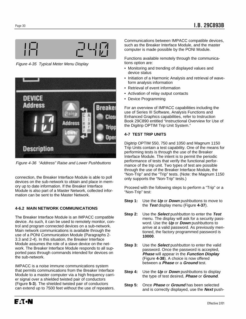
I.B. 29C893BPage 30
Effective 2/01
Communications between IMPACC compatible devices,such as the Breaker Interface Module, and the mastercomputer is made possible by the PONI Module.
Functions available remotely through the communica-tions option are:• Monitoring and trending of displayed values and
device status• Initiation of a Harmonic Analysis and retrieval of wave-
form analysis information• Retrieval of event information• Activation of relay output contacts• Device Programming
For an overview of IMPACC capabilities including theuse of Series III Software, Analysis Functions andEnhanced Graphics capabilities, refer to InstructionBook 29C890 entitled “Instructional Overview for Use ofthe Digitrip OPTIM Trip Unit System.”
4-7 TEST TRIP UNITS
Digitrip OPTIM 550, 750 and 1050 and Magnum 1150Trip Units contain a test capability. One of the means forperforming tests is through the use of the BreakerInterface Module. The intent is to permit the periodicperformance of tests that verify the functional perfor-mance of the trip unit. Two types of test are possiblethrough the use of the Breaker Interface Module, the“Non-Trip” and the “Trip” tests. (Note: the Magnum 1150only supports the “Non-Trip” tests.)
Proceed with the following steps to perform a “Trip” or a“Non-Trip” test:
Step 1: Use the Up or Down pushbuttons to move tothe Test display menu (Figure 4-37).
Step 2: Use the Select pushbutton to enter the Testmenu. The display will ask for a security pass-word. Use the Up or Down pushbuttons toarrive at a valid password. As previously men-tioned, the factory programmed password is10000.
Step 3: Use the Select pushbutton to enter the validpassword. Once the password is accepted,Phase will appear in the Function Display(Figure 4-38). A choice is now offeredbetween a Phase or a Ground test.
Step 4: Use the Up or Down pushbuttons to displaythe type of test desired, Phase or Ground .
Step 5: Once Phase or Ground has been selectedand is correctly displayed, use the Next push-
Figure 4-36 “Address” Raise and Lower Pushbuttons
connection, the Breaker Interface Module is able to polldevices on the sub-network to obtain and place in mem-ory up to date information. If the Breaker InterfaceModule is also part of a Master Network, collected infor-mation can be sent to the Master Network.
4-6.2 MAIN NETWORK COMMUNICATIONS
The Breaker Interface Module is an IMPACC compatibledevice. As such, it can be used to remotely monitor, con-trol and program connected devices on a sub-network.Main network communications is available through theuse of a PONI Communication Module (Paragraphs 2-3.3 and 2-4). In this situation, the Breaker InterfaceModule assumes the role of a slave device on the net-work. The Breaker Interface Module responds to all sup-ported pass through commands intended for devices onthe sub-network.
IMPACC is a noise immune communications systemthat permits communications from the Breaker InterfaceModule to a master computer via a high frequency carri-er signal over a shielded twisted pair of conductors(Figure 5-3). The shielded twisted pair of conductorscan extend up to 7500 feet without the use of repeaters.
Figure 4-35 Typical Meter Menu Display
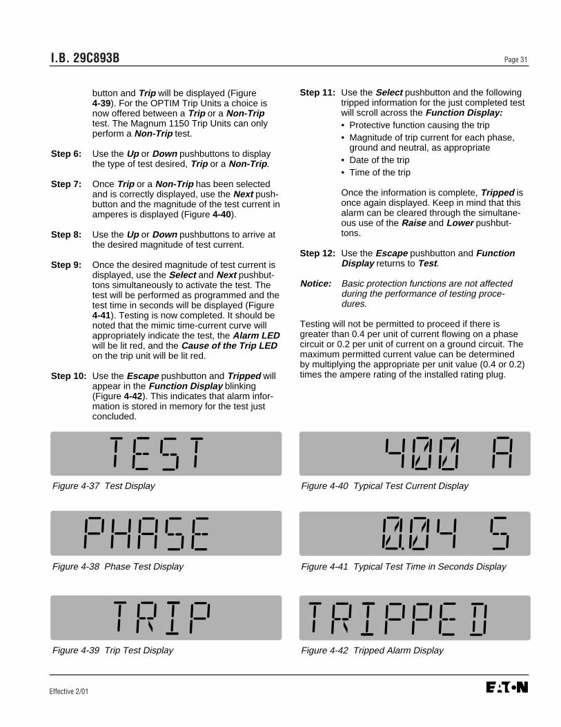
I.B. 29C893B Page 31
Effective 2/01
button and Trip will be displayed (Figure 4-39). For the OPTIM Trip Units a choice isnow offered between a Trip or a Non-Triptest. The Magnum 1150 Trip Units can onlyperform a Non-Trip test.
Step 6: Use the Up or Down pushbuttons to displaythe type of test desired, Trip or a Non-Trip .
Step 7: Once Trip or a Non-Trip has been selectedand is correctly displayed, use the Next push-button and the magnitude of the test current inamperes is displayed (Figure 4-40).
Step 8: Use the Up or Down pushbuttons to arrive atthe desired magnitude of test current.
Step 9: Once the desired magnitude of test current isdisplayed, use the Select and Next pushbut-tons simultaneously to activate the test. Thetest will be performed as programmed and thetest time in seconds will be displayed (Figure4-41). Testing is now completed. It should benoted that the mimic time-current curve willappropriately indicate the test, the Alarm LEDwill be lit red, and the Cause of the Trip LEDon the trip unit will be lit red.
Step 10: Use the Escape pushbutton and Tripped willappear in the Function Display blinking(Figure 4-42). This indicates that alarm infor-mation is stored in memory for the test justconcluded.
Figure 4-37 Test Display
Figure 4-38 Phase Test Display
Figure 4-39 Trip Test Display
Figure 4-40 Typical Test Current Display
Figure 4-41 Typical Test Time in Seconds Display
Figure 4-42 Tripped Alarm Display
Step 11: Use the Select pushbutton and the followingtripped information for the just completed testwill scroll across the Function Display:• Protective function causing the trip• Magnitude of trip current for each phase,
ground and neutral, as appropriate• Date of the trip• Time of the trip
Once the information is complete, Tripped isonce again displayed. Keep in mind that thisalarm can be cleared through the simultane-ous use of the Raise and Lower pushbut-tons.
Step 12: Use the Escape pushbutton and FunctionDisplay returns to Test .
Notice: Basic protection functions are not affectedduring the performance of testing proce-dures.
Testing will not be permitted to proceed if there isgreater than 0.4 per unit of current flowing on a phasecircuit or 0.2 per unit of current on a ground circuit. Themaximum permitted current value can be determinedby multiplying the appropriate per unit value (0.4 or 0.2)times the ampere rating of the installed rating plug.

I.B. 29C893BPage 32
Effective 2/01
SECTION 5: INSTALLATION, STARTUPAND TESTING
5-1 INTRODUCTION
This section describes mounting, wiring, startup andmiscellaneous testing details associated with theBreaker Interface Module. Earlier sections, especiallySections 1 and 2, should be reviewed prior to installingthe Breaker Interface Module.
INSURE THAT ANY INCOMING AC POWERSOURCES ARE TURNED OFF AND LOCKED OUTBEFORE PERFORMING ANY WORK ON THEBREAKER INTERFACE MODULE OR ITS ASSOCIAT-ED EQUIPMENT. FAILURE TO OBSERVE THISPRACTICE COULD RESULT IN SERIOUS INJURY,DEATH OR EQUIPMENT DAMAGE.
5-2 PANEL PREPARATION
Panel preparation and mounting of the Breaker InterfaceModule is described for a standard flush mounted instal-lation.
5-2.1 CUTOUT
Since the Breaker Interface Module is typically mountedon an enclosure door, it is necessary to prepare a cutoutin which it will be placed. The dimensions for this cutoutalong with mounting hole locations are shown in Figure5-1. Note that the Breaker Interface Module has tenmounting holes. Normally the top, bottom and centerholes are used for a standard installation. If the installa-tion is to be in a NEMA 3R or 4 enclosure, additionalmounting holes are provided so that uniform pressurecan be maintained on a gasket all the way around theunit.
Before actually cutting the panel, be sure that the re-quired 3-dimensional clearances for the device’s chas-sis allow mounting in the desired location. BreakerInterface Module dimensions with and without a Com-munication Module (PONI) and external power supplyare shown in Figure 5-2.
It is necessary to hold the tolerance shown when mak-ing the cutouts and placing the holes for the mountingscrews. In particular, the horizontal dimensions betweenthe center of the mounting holes and the vertical edge ofthe cutout must be within 0 and +0.050 inch (0.13 cm).
5-2.2 MOUNTING
Do not use a tap on the face of the Breaker InterfaceModule since this will remove excessive plastic from theholes. This will result in less threaded material to securethe unit to its mounting panel.
Place the Breaker Interface Module through the cutout inthe panel. Be sure the Operator Panel faces outward. Usethe #10 x 0.375 inch Hilo Pan Head screws included withthe unit to mount it on a single-thickness panel. Be sure tostart the screws from INSIDE THE PANEL, so they gothrough the metal first.
5-2.3 MISCELLANEOUS MOUNTING DETAILS
When field installing a Communications Module (PONI),carefully follow all the installation instructions suppliedwith the PONI. In addition, be certain that DIP Switch 6is set as specified in Table 5.1.
5.12
2.22
5.38
2.56
0.25
0.13
.201 Dia.(6 Holes)
2.22
9.38
4.44
4.44
0
0
Figure 5-1 Cutout Dimensions and Drilling Pattern (inches)
! WARNING

I.B. 29C893B Page 33
Effective 2/01
5-3 WIRING
Wiring of the Breaker Interface Module should follow asuitable wiring plan drawing. The phrase “wiring plandrawing” refers to the drawing or drawings made for thespecific application. It describes all electrical connec-tions between the Breaker Interface Module and exter-nal equipment. This drawing is the responsibility of theuser or OEM. A network wiring diagram can also behelpful for sub-network and network systems (Figure 5-3). The Breaker Interface Module rear connections/DIPswitch diagram (Figure 5-4) will assist with the creationof a wiring plan drawing.
The following general considerations should be com-plied with during the wiring process:
1. All wiring must conform to applicable Federal, Stateand Local codes.
2. Wires to the terminal blocks must not be larger thanAWG No. 14. Larger wire will not connect properly tothe terminal blocks.
3. Terminal blocks have No. 6-32 sems pressure sad-dle screws.
4. Wiring diagram relay contacts are shown in their de-energized position.
5. The Breaker Interface Module chassis must be con-nected to ground. A good low impedance chassisground is essential for proper functioning.
5-4 INITIAL STARTUP
This information is intended to be used when first apply-ing control power to the Breaker Interface Module.
Figure 5-2 Breaker Interface Module Dimensions (inches)

Effective 2/01
I.B. 29C893BPage 34
Figure 5-3 Typical Network Wiring Diagram
IBM CompatibleComputer
BreakerInterfaceModule
ShieldedTwistedPair
SPBCircuit Breaker
with OPTIM
DSIICircuitBreaker
withOPTIM
Series CR-Frame
MCCBwith
OPTIM
PONI
Series CN-Frame
MCCBwith
OPTIM
Series CL-FrameMCCBwith
OPTIM
Circuit Breaker
with RMS 810
or 910
Series CF-FrameMCCB
ES
IQ Energy Sentinel
ShieldedTwistedPair
PONI Module(Required for IMPACC
Network Communications)
ShieldedTwisted
Pair
➄ TerminatingResistor
➃
➁
➁ ➁
➁➁
➀ ➂
➄ TerminatingResistor
➃
➀
➆
➅
➀
Series CK-Frame
MCCBwith
OPTIM
➀ For network interconnection cable, use Belden 9463 or Cutler-HammerIMPCABLE.
➁ When interconnecting devices, tieshield drain wires together for shieldpath continuity.
➂ Connect the shield path to a solidearth ground at one point only.
➃ On last device in network, tape shielddrain wire back upon cable.
➄ Use a 1/2 watt carbon or metal filmresistor at each end of the network as an end of line termination resistor(EOLTR). EOLTR should be 100 ohmsfor 9600 baud communication rate networks or 150 ohms for 1200 baudcommunication rate networks.
➅ Network interconnection to computerrequires use of an IMPACC master(CONI or MINT).
➆ Devices without built-in communica-tions require network interface module(PONI).
For detailed network wiring specifications,call the automatic fax retrieval system(FRED) at 412/494-3745 and request
document 17513 or contact the Advanced Products Support Center.
Refer to the paragraph entitled “Technical Assistance” in this document.
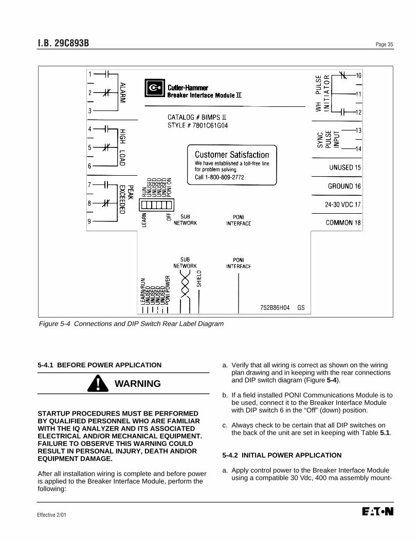
I.B. 29C893B Page 35
Effective 2/01
5-4.1 BEFORE POWER APPLICATION
STARTUP PROCEDURES MUST BE PERFORMEDBY QUALIFIED PERSONNEL WHO ARE FAMILIARWITH THE IQ ANALYZER AND ITS ASSOCIATEDELECTRICAL AND/OR MECHANICAL EQUIPMENT.FAILURE TO OBSERVE THIS WARNING COULDRESULT IN PERSONAL INJURY, DEATH AND/OREQUIPMENT DAMAGE.
After all installation wiring is complete and before poweris applied to the Breaker Interface Module, perform thefollowing:
a. Verify that all wiring is correct as shown on the wiringplan drawing and in keeping with the rear connectionsand DIP switch diagram (Figure 5-4).
b. If a field installed PONI Communications Module is tobe used, connect it to the Breaker Interface Modulewith DIP switch 6 in the “Off” (down) position.
c. Always check to be certain that all DIP switches onthe back of the unit are set in keeping with Table 5.1.
5-4.2 INITIAL POWER APPLICATION
a. Apply control power to the Breaker Interface Moduleusing a compatible 30 Vdc, 400 ma assembly mount-
Figure 5-4 Connections and DIP Switch Rear Label Diagram
! WARNING

I.B. 29C893BPage 36
Effective 2/01
ed power supply or a Breaker Interface Modulemounted power supply. Refer to Table 2.1 for exactpower supply information and requirements.
b. The Operational LED will blink green indicating agood operational status and Cutler-Hammer will bebriefly displayed. If the Operational LED is not lit oris on continuously, a problem is indicated. Removepower from the Breaker Interface Module and refer tothe Troubleshooting Guide (Table 6.1).
c. To proceed beyond this point, refer to operationalinstructions presented in Section 4 to configure andsetup particular devices.
Table 5.1 Operational DIP Switch Settings
Switch UP Position Down Position
1 Run Mode - Normal switch position once Learn Mode - Switch position during initial power the Breaker Interface Module has learned application to the Breaker Interface Module or the identity of connected devices. during the use of the Update feature of the
System display menu.
2, 3, 4 and 5 Unused Unused
6 Switch position when a PONI is used to Switch position when PONI is not being used for communicate over an IMPACC network. communications, or when PONI is being installed (“On” position) or removed from the Breaker Interface Module.
(“Off” position)
Note: Refer to Paragraph 2-3.1 for additional information.
I.B. 29C893B Page 37
Effective 2/01
SECTION 6: TROUBLESHOOTING ANDMAINTENANCE
6-1 LEVEL OF REPAIR
This manual is written based on the assumption thatonly unit-level troubleshooting will be performed. If thecause of a malfunction is traced to a Breaker InterfaceModule, the device should be replaced. The malfunc-tioning device should be returned to Cutler-Hammer.
6-2 TROUBLESHOOTING
Refer to Table 6.1 for troubleshooting guidelines.
6-3 REPLACEMENT
Follow these procedural steps to replace the BreakerInterface Module.
Step 1: Turn off control power at the main disconnect orisolation switch of the control power supply. If theswitch is not located in view from the BreakerInterface Module, lock it out to guard againstother personnel accidentally turning it on.
Step 2: Verify that all power sources wired to theBreaker Interface Module are deenergized.These may also be present on the relay andinput/output terminal block.
Step 3: Before disconnecting any wires from the unit,make sure they are individually identified toassure that reconnection can be correctly per-formed. Make a sketch to help with the task ofterminal and wire identification.
Step 4: If an optional ribbon cable connects with theCommunications Port, carefully disconnect it.
Step 5: Remove wires by loosening or removing thescrew terminal where there is a wire connec-tion.
SUPPORT THE BREAKER INTERFACE MODULEFROM THE FRONT SIDE WHEN THE SCREWS ARE
LOOSENED OR REMOVED IN STEP 6. WITHOUTSUCH SUPPORT, THE UNIT COULD FALL OR THEPANEL COULD BE DAMAGED.
Step 6: Remove the 6 mounting screws holding theunit against the door or panel. These areaccessed from the rear of the unit.
Step 7: Carefully lay the screws aside for later use.
Step 8: Mount the replacement unit. Read paragraph5-2.2 before attempting this.
Step 9: Reverse the procedure just outlined in Steps 4through 6.
Step 10: Using the sketch mentioned in Step 3, replaceeach wire at the correct terminal. Be sure thateach is firmly tightened. Remove temporaryshorts on incoming current transformers.
Step 11: Restore control power. Refer to paragraphs 5-4.2 entitled “Initial Power Application.”
6-4 MAINTENANCE AND CARE
The Breaker Interface Module is designed to be a selfcontained and maintenance free device.
The Breaker Interface Module should be stored in anenvironment that does not exceed the storage tempera-ture range of -30°C to +85°C. The environment shouldalso be free of excess humidity. Store the device in itsoriginal packing material.
6-5 RETURN PROCEDURE
The Troubleshooting Guide (Table 6.1) is intended forservice personnel to identify whether a problem beingobserved is external or internal to the device. If a prob-lem is determined to be internal, the device should bereturned to the factory for replacement. To have aBreaker Interface Module returned, contact your localCutler-Hammer authorized distributor.
6-6 TECHNICAL ASSISTANCE
For information, technical assistance or referral to alocal authorized distributor, contact the AdvancedProduct Support Center at 1-800-809-2772.
! CAUTION
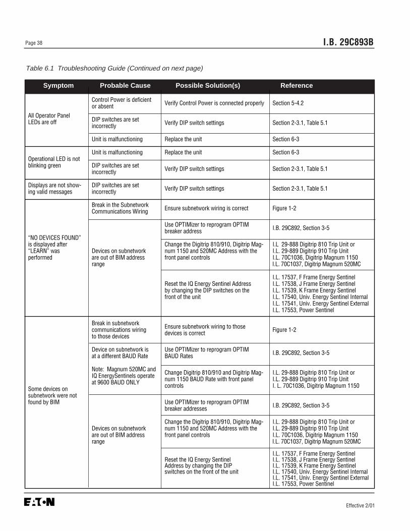
Effective 2/01
I.B. 29C893BPage 38
Control Power is deficient Verify Control Power is connected properly Section 5-4.2or absent
All Operator PanelLEDs are off DIP switches are set Verify DIP switch settings Section 2-3.1, Table 5.1incorrectly
Unit is malfunctioning Replace the unit Section 6-3
Unit is malfunctioning Replace the unit Section 6-3Operational LED is notblinking green DIP switches are set Verify DIP switch settings Section 2-3.1, Table 5.1incorrectly
Displays are not show- DIP switches are set Verify DIP switch settings Section 2-3.1, Table 5.1ing valid messages incorrectly
Break in the Subnetwork Ensure subnetwork wiring is correct Figure 1-2Communications Wiring
Use OPTIMizer to reprogram OPTIM I.B. 29C892, Section 3-5breaker address“NO DEVICES FOUND” is displayed after Change the Digitrip 810/910, Digitrip Mag- I.L 29-888 Digitrip 810 Trip Unit or“LEARN” was Devices on subnetwork num 1150 and 520MC Address with the I.L. 29-889 Digitrip 910 Trip Unitperformed are out of BIM address front panel controls I.L. 70C1036, Digitrip Magnum 1150
range I.L. 70C1037, Digitrip Magnum 520MC
I.L. 17537, F Frame Energy SentinelReset the IQ Energy Sentinel Address I.L. 17538, J Frame Energy Sentinelby changing the DIP switches on the I.L. 17539, K Frame Energy Sentinelfront of the unit I.L. 17540, Univ. Energy Sentinel Internal
I.L. 17541, Univ. Energy Sentinel ExternalI.L. 17553, Power Sentinel
Break in subnetwork Ensure subnetwork wiring to those communications wiring devices is correct Figure 1-2to those devices
Device on subnetwork is Use OPTIMizer to reprogram OPTIM I.B. 29C892, Section 3-5at a different BAUD Rate BAUD Rates
Note: Magnum 520MC and Change Digitrip 810/910 and Digitrip Mag- I.L. 29-888 Digitrip 810 Trip Unit orIQ EnergySentinels operate num 1150 BAUD Rate with front panel I.L. 29-889 Digitrip 910 Trip Unit at 9600 BAUD ONLY controls I. L. 70C1036, Digitrip Magnum 1150Some devices onsubnetwork were notfound by BIM Use OPTIMizer to reprogram OPTIM I.B. 29C892, Section 3-5breaker addresses
Change the Digitrip 810/910, Digitrip Mag- I.L. 29-888 Digitrip 810 Trip Unit orDevices on subnetwork num 1150 and 520MC Address with the I.L. 29-889 Digitrip 910 Trip Unit are out of BIM address front panel controls I.L. 70C1036, Digitrip Magnum 1150 range I.L. 70C1037, Digitrip Magnum 520MC
I.L. 17537, F Frame Energy SentinelReset the IQ Energy Sentinel I.L. 17538, J Frame Energy SentinelAddress by changing the DIP I.L. 17539, K Frame Energy Sentinelswitches on the front of the unit I.L. 17540, Univ. Energy Sentinel Internal
I.L. 17541, Univ. Energy Sentinel ExternalI.L. 17553, Power Sentinel
Table 6.1 Troubleshooting Guide (Continued on next page)
Symptom Probable Cause Possible Solution(s) Reference
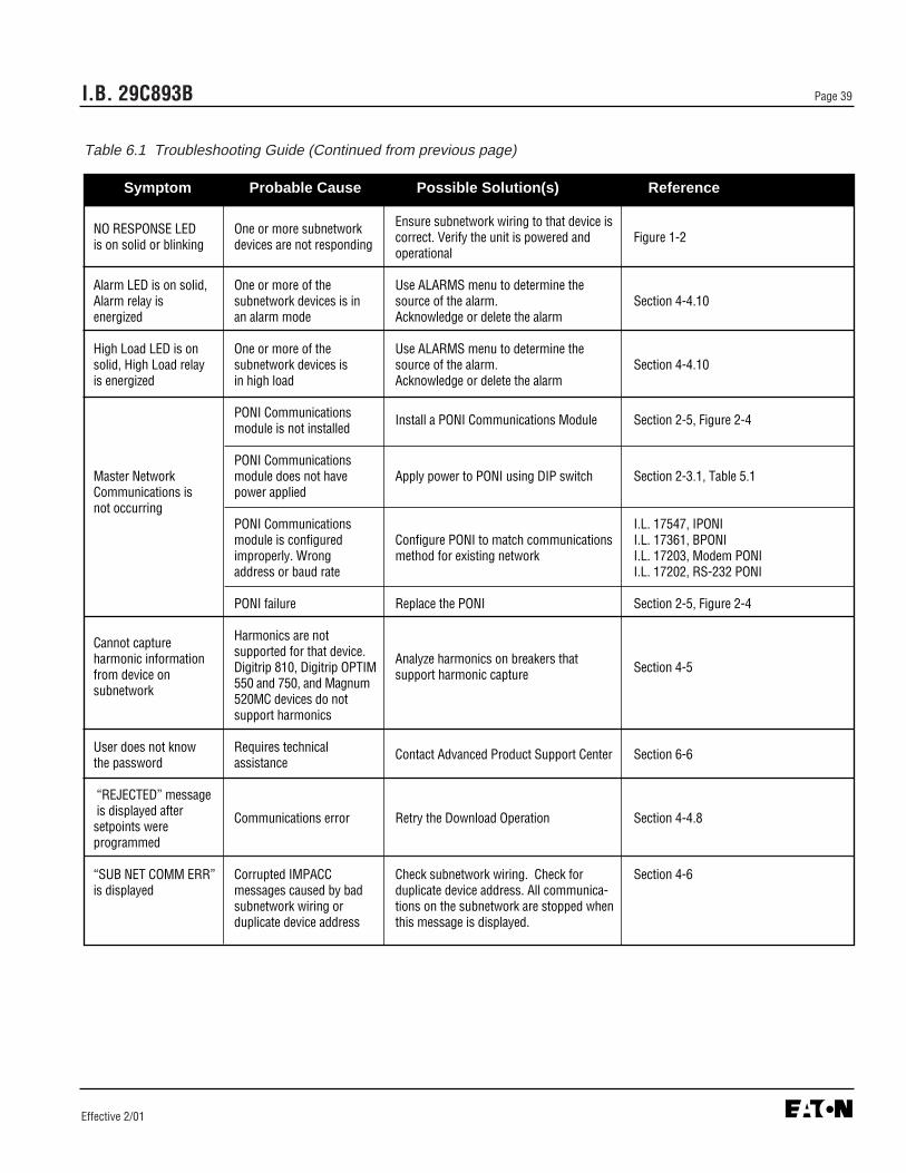
Effective 2/01
NO RESPONSE LED One or more subnetwork Ensure subnetwork wiring to that device is
is on solid or blinking devices are not responding correct. Verify the unit is powered and Figure 1-2operational
Alarm LED is on solid, One or more of the Use ALARMS menu to determine the Alarm relay is subnetwork devices is in source of the alarm. Section 4-4.10energized an alarm mode Acknowledge or delete the alarm
High Load LED is on One or more of the Use ALARMS menu to determine the solid, High Load relay subnetwork devices is source of the alarm. Section 4-4.10is energized in high load Acknowledge or delete the alarm
PONI Communications Install a PONI Communications Module Section 2-5, Figure 2-4module is not installed
PONI CommunicationsMaster Network module does not have Apply power to PONI using DIP switch Section 2-3.1, Table 5.1Communications is power appliednot occurring
PONI Communications I.L. 17547, IPONImodule is configured Configure PONI to match communications I.L. 17361, BPONIimproperly. Wrong method for existing network I.L. 17203, Modem PONIaddress or baud rate I.L. 17202, RS-232 PONI
PONI failure Replace the PONI Section 2-5, Figure 2-4
Cannot capture Harmonics are not
harmonic information supported for that device. Analyze harmonics on breakers that from device on Digitrip 810, Digitrip OPTIM support harmonic capture Section 4-5
subnetwork 550 and 750, and Magnum 520MC devices do not support harmonics
User does not know Requires technical Contact Advanced Product Support Center Section 6-6the password assistance
“REJECTED” messageis displayed after Communications error Retry the Download Operation Section 4-4.8setpoints were programmed
“SUB NET COMM ERR” Corrupted IMPACC Check subnetwork wiring. Check for Section 4-6is displayed messages caused by bad duplicate device address. All communica-
subnetwork wiring or tions on the subnetwork are stopped when duplicate device address this message is displayed.
I.B. 29C893B Page 39
Symptom Probable Cause Possible Solution(s) Reference
Table 6.1 Troubleshooting Guide (Continued from previous page)
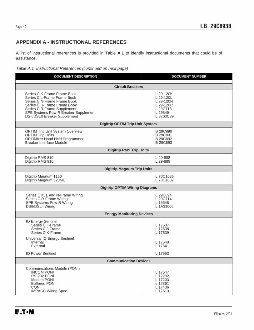
Effective 2/01
I.B. 29C893BPage 40
APPENDIX A - INSTRUCTIONAL REFERENCES
A list of instructional references is provided in Table A.1 to identify instructional documents that could be ofassistance.
Table A.1 Instructional References (continued on next page)
DOCUMENT DESCRIPTION DOCUMENT NUMBER
Circuit Breakers
Series C K-Frame Frame Book IL 29-120KSeries C L-Frame Frame Book IL 29-120LSeries C N-Frame Frame Book IL 29-120NSeries C R-Frame Frame Book IL 29-120RSeries C R-Frame Supplement IL 29C713SPB Systems Pow-R Breaker Supplement IL 29849DSII/DSLII Breaker Supplement IL 8700C39
Digitrip OPTIM Trip Unit System
OPTIM Trip Unit System Overview IB 29C890OPTIM Trip Units IB 29C891OPTIMizer Hand Held Programmer IB 29C892Breaker Interface Module IB 29C893
Digitrip RMS Trip Units
Digitrip RMS 810 IL 29-888Digitrip RMS 910 IL 29-889
Digitrip Magnum Trip Units
Digitrip Magnum 1150 IL 70C1036Digitrip Magnum 520MC IL 70C1037
Digitrip OPTIM Wiring Diagrams
Series C K, L and N-Frame Wiring IL 29C894Series C R-Frame Wiring IL 29C714SPB Systems Pow-R Wiring IL 15545DSII/DSLII Wiring IL 1A33600
Energy Monitoring Devices
IQ Energy Sentinel Series C F-Frame IL 17537Series C J-Frame IL 17538Series C K-Frame IL 17539
Universal IQ Energy Sentinel Internal IL 17540External IL 17541
IQ Power Sentinel IL 17553
Communication Devices
Communications Module (PONI) INCOM PONI IL 17547RS-232 PONI IL 17202Modem PONI IL 17203Buffered PONI IL 17361CONI IL 17436IMPACC Wiring Spec. IL 17513

Effective 2/01
I.B. 29C893B Page 41
Table A.1 Instructional References (continued from previous page)
DOCUMENT DESCRIPTION DOCUMENT NUMBER
Accessories
Potential Transformer Module (K, L and N-Frame) 29C126
Ground Fault Indicator 1259C14G01
Digitrip OPTIM Time-Current Curves
Series C K-Frame CurvesI2t Long & Short Delay Phase SC-6924-98I2t Long & Flat Short Delay Phase SC-6925-98I4t Long & Flat Short Delay Phase SC-6926-98400A Instantaneous & Override Phase SC-6927-98250A Instantaneous & Override Phase SC-6928-98125A Instantaneous & Override Phase SC-6929-98Ground Fault Protection SC-6930-98
Series C L-Frame CurvesI2t Long & Short Delay Phase SC-6323-96I2t Long & Flat Short Delay Phase SC-6324-96I4t Long & Flat Short Delay Phase SC-6325-96600A Instantaneous & Override Phase SC-6326-96400A Instantaneous & Override Phase SC-6327-96Ground Fault Protection SC-6330-96
Series C N-Frame CurvesI2t Long & Short Delay Phase SC-6331-96I2t Long & Flat Short Delay Phase SC-6332-96I4t Long & Flat Short Delay Phase SC-6333-96Instantaneous & Override Phase SC-6334-96Ground Fault Protection SC-6335-96
Series C R-Frame Curves1600/2000A I2t Long & Short Delay Phase SC-6336-961600/2000A I2t Long & Flat Short Delay Phase SC-6337-961600/2000A I4t Long & Flat Short Delay Phase SC-6338-962500A I2t Long & Short Delay Phase SC-6339-962500A I2t Long & Flat Short Delay Phase SC-6340-962500A I4t Long & Flat Short Delay Phase SC-6341-961600A Instantaneous & Override Phase SC-6342-96 2000A Instantaneous & Override Phase SC-6343-96 2500A Instantaneous & Override Phase SC-6344-961600A Ground Fault Protection SC-6345-96 2000A Ground Fault Protection SC-6346-96 2500A Ground Fault Protection SC-6347-96
SPB Systems Pow-R Curves400-1200A I2t Long & Short Delay Phase SC-6348-96400-1200A I2t Long & Flat Short Delay Phase SC-6349-96400-1200A I4t Long & Flat Short Delay Phase SC-6350-961600-3000A I2t Long & Short Delay Phase SC-6351-961600-3000A I2t Long & Flat Short Delay Phase SC-6352-961600-3000A I4t Long & Flat Short Delay Phase SC-6353-964000-5000A I2t Long & Short Delay Phase SC-6354-964000-5000A I2t Long & Flat Short Delay Phase SC-6355-964000-5000A I4t Long & Flat Short Delay Phase SC-6356-96400-1200A Instantaneous & Override Phase SC-6357-961600-3000A Instantaneous & Override Phase SC-6358-964000-5000A Instantaneous & Override Phase SC-6359-96Ground Fault Protection SC-6360-96
DSII/DSLII Curves400-1200A I2t Long & Short Delay Phase SC-6275-95400-1200A I2t Long & Flat Short Delay Phase SC-6276-95400-1200A I4t Long & Flat Short Delay Phase SC-6277-951600-5000A I2t Long & Short Delay Phase SC-6278-951600-5000A I2t Long & Flat Short Delay Phase SC-6279-951600-5000A I4t Long & Flat Short Delay Phase SC-6280-95400-1200A Instantaneous & Override Phase SC-6281-961600-5000A Instantaneous & Override Phase SC-6282-96Ground Fault Protection SC-6283-96
Magnum DS CurvesDigitrip 220 (LI) 70C1009Digitrip 520 70C1006-1008Digitrip 1150 70C1031-1043

I.B. 29C893B
Cutler-HammerPittsburgh, Pennsylvania U.S.A.
Effective 2/01Style 7801C98H03Printed in U.S.A.
This instruction booklet is published solely for informa-tion purposes and should not be considered all inclu-sive. If further information is required, you should con-sult Cutler-Hammer.
Sale of product shown in this literature is subject toterms and conditions outlined in appropriate Cutler-Hammer selling policies or other contractual agreementbetween the parties. This literature is not intended toand does not enlarge or add to any such contract. Thesole source governing the rights and remedies of anypurchaser of this equipment is the contract between thepurchaser and Cutler-Hammer.
NO WARRANTIES, EXPRESSED OR IMPLIED,INCLUDING WARRANTIES OF FITNESS FOR A PAR-TICULAR PURPOSE OR MERCHANTABILITY, ORWARRANTIES ARISING FROM COURSE OF DEAL-ING OR USAGE OF TRADE, ARE MADE REGARDINGTHE INFORMATION, RECOMMENDATIONS ANDDESCRIPTIONS CONTAINED HEREIN. In no eventwill Cutler-Hammer be responsible to the purchaser oruser in contract, in tort (including negligence), strict lia-bility or otherwise for any special, indirect, incidental orconsequential damage or loss whatsoever, including butnot limited to damage or loss of use of equipment, plantor power system, cost of capital, loss of power, addition-al expenses in the use of existing power facilities, orclaims against the purchaser or user by its customersresulting from the use of the information, recommenda-tions and description contained herein.