cut to the sub-base - autodesk community · developing plans based on land survey data, developing...
TRANSCRIPT

1
Cut to the Sub-base
Christina A. Davis – Microdesk
CV114-2
Existing surface? Check. Corridor, proposed surface? Check, check. Volume report? Zero! Quantity takeoffs are a vital part of the estimating process and AutoCAD Civil 3D has the tools you need to get the numbers you want. This class will walk you through the Civil 3D process for calculating earthwork volumes and material takeoffs using surfaces and corridors. We'll dig through the missteps that cause zero volumes and cut right to the sub-base.
About the Speaker:
Christina works at Microdesk providing technical support, training, and other consulting services to civil clients nationwide. She has over 9 years of experience with CAD applications and has been working with AutoCAD since Release 12. Prior to joining Microdesk, Christina worked with well-known Boston surveying firms developing plans based on land survey data, developing and detailing existing- and new-conditions plans based on civil survey data, digitization of site conditions, and the designation and compilation of utilities. Christina has extensive knowledge of AutoCAD, AutoCAD Land Desktop, AutoCAD Civil 3D, and AutoCAD Architecture. She holds a degree in Architectural Technology

2

3
Cut to the Sub-base
Introduction
This class is intended for the intermediate Civil 3D 2008 user. You should have familiarity with the Civil 3D interface, styles, and objects including alignments, profiles, and corridors.
Ready?
Our starting point will be our corridor model. To get there you will need
Existing surface: a three-dimensional geometric representation of an area of land made up of triangles or grids, which are created when Civil 3D connects the points that make up the surface data.
Alignment: centerline defining a horizontal path which, when combined with a profile, creates the baseline of a corridor
Profile: vertical alignment which defines surface elevations along the horizontal alignment.
Assembly: combines one or more subassemblies to represent a typical section
Subassembly: defines the geometry of a component used in a corridor section, such as a lane, curb, ditch,etc.
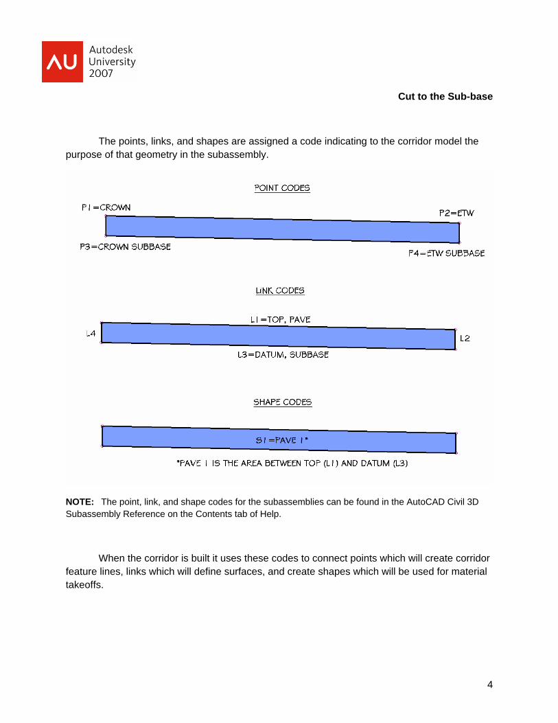
In calculating quantity takeoffs the subassembly and its predefined codes will be key. The subassembly is a collection of points, links, and shapes. A point is the endpoint of a link. A link is a straight line segment between endpoints. A shape is the enclosed area created by three or more links
4
Cut to the Sub-base
The points, links, and shapes are assigned a code indicating to the corridor model the purpose of that geometry in the subassembly.
NOTE: The point, link, and shape codes for the subassemblies can be found in the AutoCAD Civil 3D Subassembly Reference on the Contents tab of Help.
When the corridor is built it uses these codes to connect points which will create corridor feature lines, links which will define surfaces, and create shapes which will be used for material takeoffs.

5
Cut to the Sub-base
From the Corridor Properties dialog box we can create corridor surfaces based on the link codes
1. On the Surfaces tab select the Create a corridor surface icon
2. A new surface entry will appear. It’s a good idea to rename the surface now to indicate which code is defining it.
3. And don’t forget to actually define it! We’ve created the surface but it’s empty, so from the Specify code drop down select the link code that will build the surface.
4. For our earthwork estimates we’ll want to compare the Datum of our corridor and the
Existing surface, so select Datum and click the blue plus icon

6
Cut to the Sub-base
Before we leave this dialog box we also want to set the surface’s boundaries to clean up any over zealous triangulation; namely in concave areas along the corridor especially along curves.
1. On the Boundaries tab you’ll see an entry for the corridor surface we just created. Right click the surface name, select Add Automatically.
2. This is where the points from the subassembly come into play. The points connect station to station, to create corridor feature lines. This automatic boundaries listed are those feature lines.
3. Select Daylight and then OK to close the dialog box.

7
Cut to the Sub-base
OK, now we’re ready! Right? Not quite but we’re close. Once the corridor is created Civil 3D’s quantity takeoff process basically breaks down to just five steps:
1. Create Sample Lines
2. Create Quantity Takeoff Criteria
3. Compute Materials
4. Create reports
Set…
Let’s first talk about the type of quantity takeoffs Civil 3D generates: Earthworks and Material Volume.
8
Cut to the Sub-base
Earthwork volumes
Earthwork volumes are the amount of material that will be brought onto or taken off the site to complete our design. The calculation compares our Existing surface and our Datum surface created from corridor links. Our goal is to have a balance between cut (material to remove) and fill (material to add). Unfortunately not all of the cut material is reusable (got rocks?). An excessive amount of either can be very expensive, so the numbers in the quantity takeoff report may lead to changes in the design.
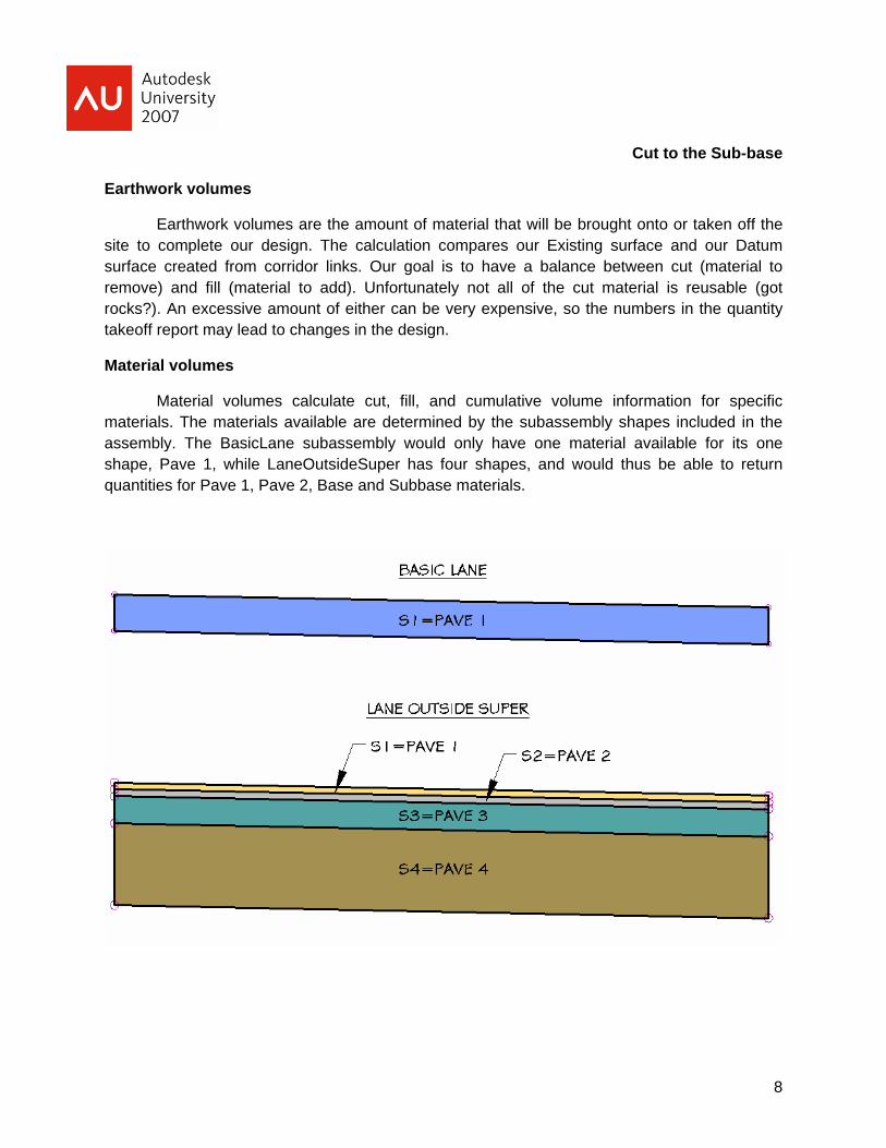
Material volumes
Material volumes calculate cut, fill, and cumulative volume information for specific materials. The materials available are determined by the subassembly shapes included in the assembly. The BasicLane subassembly would only have one material available for its one shape, Pave 1, while LaneOutsideSuper has four shapes, and would thus be able to return quantities for Pave 1, Pave 2, Base and Subbase materials.

9
Cut to the Sub-base
Step 1: Create Sample Lines
Sample lines are linear objects that are used to cut sections across an alignment. Sections are cut along each of the samples lines for a specified set of data, such as our surfaces and corridor. A set of sample lines makes up a named collection called a sample line group. The sample lines can then be used to create cross section views. For quantity takeoffs sample lines are critical because they do actually sample the data, determining what materials (shapes) are present in the corridor.
1. From the Sections menu select Create sample lines
2. Select the alignment the sample lines will be tied to
3. In the Create Sample Line Group dialog box we’ll select the data sources we need to sample. The Existing surface, Corridor model, and the Datum surface must all be included to complete our quantity takeoffs.

10
Cut to the Sub-base
4. From the Sample Line Tools toolbar, in the Sample Line creation methods list (drop down), select an option. I recommend using From corridor stations or By range of stations, as the other three options are more manual.
5. In the Create Sample Lines dialog edit station range along the alignment and swath widths. Click OK.

11
Cut to the Sub-base
6. The command line will continue to prompt “Specify station:” but if you look at your plan the sample lines have been created. Enter to finish Create sample lines command.
A common mistake made with this step is with the introduction of new data sources. Let’s say I create my corridor model and then create sample lines. I now remember that I need to create the Datum corridor surface, which I do from corridor properties. That original sample line group will only have sampled the Existing surface and the Corridor. The Datum surface will not be automatically added.
To add the Datum surface to the same sample line group we need to Sample more sources.
1. From the Sections menu select Edit sample lines. The Sample Line Tools toolbar will open along with a blank Edit Sample Line dialog box. Notice the Sample Line Group drop down is also blank

12
Cut to the Sub-base
2. Select a sample line from the plan to populate the drop down with the specific sample line group.
3. From the Sample line group action list (drop down next to Sample line group name) select Sample more sources.
4. The Datum surface is an available source. Select the surface and then the Add button to update the sample line group. OK to close the dialog and enter to finish the Sample lines command.

13
Cut to the Sub-base
Step 2: Create Quantity Takeoff Criteria
The Quantity Takeoff Criteria tells Civil 3D which two surfaces to compare for earthworks and a list of materials (subassembly shapes). The Criteria is not meant to point to the specific surfaces or corridor shapes present in the drawing, otherwise we would be recreating this list for every project. Rather than creating Criteria that compares “Geer Road Existing” and “Geer Road Proposed Datum”, the criteria would list simply “Existing” and “Datum”. The specific mapping to the current surfaces is done in Step 3: Compute Materials.
The “AutoCAD Civil 3D (Imperial) NCS Extended.dwt” includes three Criteria: Cut and Fill, Earthworks, and Material List. We will create new Criteria called Full Criteria to combine Cut and Fill and Material List.
1. The criteria are stored in the Toolspace Settings tab under the Quantity Takeoff collection. Right click the blue Quantity Takeoff Criteria folder and select New.
2. On the information tab of the Quantity Takeoff Criteria dialog box rename the criteria.
3. On the Material List tab select Add new material and rename the new entry to Ground Removed.
4. Each new material we create will be assigned a Quantity type and where applicable Cut, Fill and Refill Factor values to account for expansion and contraction of materials during transport. The Quantity and Factor types are listed below.

14
Cut to the Sub-base
Quantity takeoff supports the following quantity types:
Cut: Used to calculate the material to remove. For example, this could be the amount below an existing ground (EG) surface and above a finished ground (FG) surface:
Fill: Used to calculate the material to add. For example, this could be the amount above an existing ground (EG) surface and below a finished ground (FG) surface:
15
Cut to the Sub-base
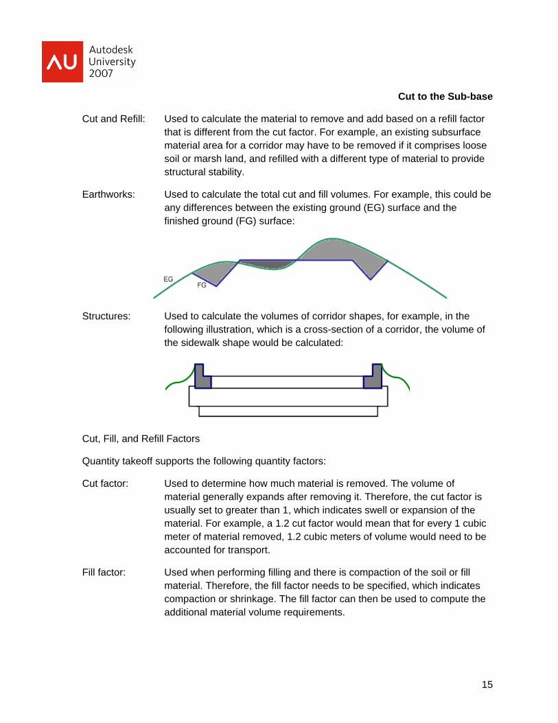
Cut and Refill: Used to calculate the material to remove and add based on a refill factor that is different from the cut factor. For example, an existing subsurface material area for a corridor may have to be removed if it comprises loose soil or marsh land, and refilled with a different type of material to provide structural stability.
Earthworks: Used to calculate the total cut and fill volumes. For example, this could be any differences between the existing ground (EG) surface and the finished ground (FG) surface:
Structures: Used to calculate the volumes of corridor shapes, for example, in the following illustration, which is a cross-section of a corridor, the volume of the sidewalk shape would be calculated:
Cut, Fill, and Refill Factors
Quantity takeoff supports the following quantity factors:
Cut factor: Used to determine how much material is removed. The volume of material generally expands after removing it. Therefore, the cut factor is usually set to greater than 1, which indicates swell or expansion of the material. For example, a 1.2 cut factor would mean that for every 1 cubic meter of material removed, 1.2 cubic meters of volume would need to be accounted for transport.
Fill factor: Used when performing filling and there is compaction of the soil or fill material. Therefore, the fill factor needs to be specified, which indicates compaction or shrinkage. The fill factor can then be used to compute the additional material volume requirements.
16
Cut to the Sub-base
Refill factor: Used to determine how much of the originally removed material can be reused. Depending on the cut material type and other considerations not all cut material is reusable (for example if it is cut from bog or marsh, the refill factor may be 0).
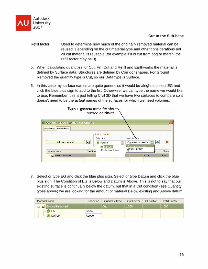
5. When calculating quantities for Cut, Fill, Cut and Refill and Earthworks the material is defined by Surface data. Structures are defined by Corridor shapes. For Ground Removed the quantity type is Cut, so our Data type is Surface.
6. In this case my surface names are quite generic so it would be alright to select EG and click the blue plus sign to add to the list. Otherwise, we can type the name we would like to use. Remember, this is just telling Civil 3D that we have two surfaces to compare so it doesn’t need to be the actual names of the surfaces for which we need volumes.
7. Select or type EG and click the blue plus sign. Select or type Datum and click the blue plus sign. The Condition of EG is Below and Datum is Above. This is not to say that our existing surface is continually below the datum, but that in a Cut condition (see Quantity types above) we are looking for the amount of material Below existing and Above datum.

17
Cut to the Sub-base
8. Select or type EG and click the blue plus sign. Select or type Datum and click the blue plus sign. The Condition of EG is Below and Datum is Above. This is not to say that our existing surface is continually below the datum, but that in a Cut condition (see Quantity types above) we are looking for the amount of material Below existing and Above datum.
9. Add a second material and rename it to Ground Fill with a Quantity type of Fill. Remain on Surface data type and add EG and Datum to the Ground Fill list. EG has a condition of Above and Datum Below.
10. For the material volumes we’ll add a new material to our Full Criteria set for each of the corridor shapes in our subassembly (think back to S1=Pave 1, etc.). Each of these will have a Quantity type of Structures, and use Corridor Shapes as the data type. Be sure to change the type to Structures before trying to add the shape data to avoid this error

18
Cut to the Sub-base
Like the surfaces, if the subassembly is in the drawing the corridor shapes will be available to add from the Select drop down, or we can type in a general name and then select the blue plus sign. The Condition will always be Include. The list should appear as below.
Step 3: Compute Materials
After we create criteria, we apply it to the sample line group to create a material list. You use the material list to generate quantity takeoff tables and reports.
1. From the Sections menu select Compute Materials. Select the correct alignment and sample line group.
2. In the Compute Materials dialog box select our Quantity takeoff criteria Full criteria. The dialog box will change to display the materials we created in Step 2. Under the Object Name column here is where we assign a specific EG surface, a specific Datum surface, etc.

19
Cut to the Sub-base
GO!
Step 4: Create reports
The Quantities Report is a file in XML format that contains the criteria definition (comparable surfaces), material types (such as cut type), shrink and swell factors, as well as refill factors. The specific format is determined by the style sheet you select.
Civil 3D includes three style sheets which are used to create external quantity takeoff reports:
Earthworks.xsl: Reports station-by-station values in a tabular format for cut and fill volumes, incremental volumes, and cumulative net volume.
Select Material.xsl: Reports station-by-station values for the selected materials. At each station, all selected materials defined in this criteria and cumulative volumes are reported.
20
Cut to the Sub-base
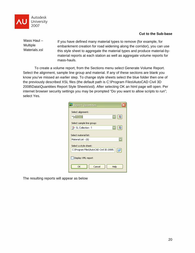
If you have defined many material types to remove (for example, for embankment creation for road widening along the corridor), you can use this style sheet to aggregate the material types and produce material-by-material reports at each station as well as aggregate volume reports for mass-hauls.
To create a volume report, from the Sections menu select Generate Volume Report. Select the alignment, sample line group and material. If any of these sections are blank you know you’ve missed an earlier step. To change style sheets select the blue folder then one of the previously described XSL files (the default path is C:\Program Files\AutoCAD Civil 3D 2008\Data\Quantities Report Style Sheets\xsl). After selecting OK an html page will open. Per internet browser security settings you may be prompted “Do you want to allow scripts to run”; select Yes.
The resulting reports will appear as below
Mass Haul – Multiple Materials.xsl

21
Cut to the Sub-base
Earthworks
Station Cut
Area (Sq.ft.)
Cut Volume (Cu.yd.)
Reusable Volume (Cu.yd.)
Fill Area
(Sq.ft.)
Fill Volume (Cu.yd.)
Cum. Cut Vol. (Cu.yd.)
Cum. Reusable
Vol. (Cu.yd.)
Cum. Fill Vol. (Cu.yd.)
Cum. Net Vol. (Cu.yd.)
7+00.000 31.83 15.28 15.28 66.48 100.15 3934.59 3934.59 3524.61 409.98
7+25.000 114.36 67.68 67.68 3.45 32.37 4002.27 4002.27 3556.98 445.29
7+50.000 245.02 166.38 166.38 1.16 2.13 4168.65 4168.65 3559.11 609.53
Select Material
Area Type Area Inc.Vol. Cum.Vol.
Sq.ft. Cu.yd. Cu.yd. Station: 7+00.000
Ground Removed 31.83 15.28 3934.59
Ground Fill 66.48 100.15 3524.61
Asphalt Top Layer 1.99 1.84 50.72
Asphalt Bottom Layer 24.00 22.22 611.09
Base 7.99 7.40 203.48
Subbase 24.00 22.22 611.03
Station: 7+25.000
Ground Removed 114.36 67.68 4002.27
Ground Fill 3.45 32.37 3556.98
Asphalt Top Layer 1.99 1.84 52.57
Asphalt Bottom Layer 24.00 22.22 633.31
Base 7.99 7.40 210.88
Subbase 24.00 22.22 633.25

22
Cut to the Sub-base
Mass Haul – Multiple Material
Area Type Area Inc.Vol. Cum.Vol. Mass Haul
Sq.ft. Cu.yd. Cu.yd. Cu.yd. Station: 7+00.000
Adjusted Cut 31.83 15.28 3934.59
Adjusted Usable 31.83 15.28 3934.59
Adjusted Fill 66.48 100.15 3524.61
409.98
Station: 7+25.000
Adjusted Cut 114.36 67.68 4002.27
Adjusted Usable 114.36 67.68 4002.27
Adjusted Fill 3.45 32.37 3556.98
445.29
We can also create Total Volume and Material table objects for direct use in the drawing. From the Sections menu select Add Tables and then Total Volume or Material Volume Table. Select alignment, sample line group, and material list. After clicking OK, select a location for the table.
23
Cut to the Sub-base
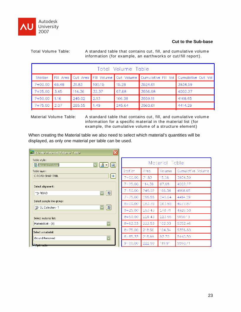
Total Volume Table: A standard table that contains cut, fill, and cumulative volume information (for example, an earthworks or cut/fill report).
Material Volume Table: A standard table that contains cut, fill, and cumulative volume information for a specific material in the material list (for example, the cumulative volume of a structure element)
When creating the Material table we also need to select which material’s quantities will be displayed, as only one material per table can be used.
24
Cut to the Sub-base
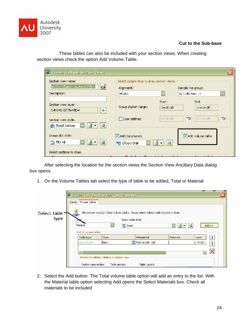
These tables can also be included with your section views. When creating section views check the option Add Volume Table.
After selecting the location for the section views the Section View Ancillary Data dialog box opens.
1. On the Volume Tables tab select the type of table to be added, Total or Material
2. Select the Add button. The Total volume table option will add an entry to the list. With the Material table option selecting Add opens the Select Materials box. Check all materials to be included

25
Cut to the Sub-base
3. The section views will appear as below with an attached table.