customizing prosthetic leg socket by using rapid prototype
TRANSCRIPT
Customizing Prosthetic Leg Socket by using Rapid Prototype with Reverse Engineering
by
Leong Song Seng
Dissertation submitted in partial fulfilment of
the requirements for the
Bachelor of Engineering (Hons)
(Mechanical Engineering)
December 2008
Universiti Teknologi PETRONAS Bandar Seri Iskandar 31750Tronoh Perak Darul Ridzuan

CERTIFICATION OF ORIGINALITY
This is to certify that I am responsible for the work submitted in this project, that the
original work is my own except as specified in the references and
acknowledgements, and that the original work contained herein have not been
undertaken or done by unspecified sources or persons.
EONG SONG SENG

CERTIFICATION OF APPROVAL
Customizing Prosthetic Leg Socket by using Rapid Prototype with Reverse Engineering
Approved by,
by
Leong Song Seng
A project dissertation submitted to the
Mechanical Engineering Programme
Universiti Teknologi PETRONAS
in partial fulfilment of the requirement for the
BACHELOR OF ENGINEERING (Hons)
(MECHANICAL ENGINEERING)
(Dr. Alunad Majdi Abdul Rani)
UNIVERSITI TEKNOLOGI PETRONAS
TRONOH, PERAK
December 2008
ii

ABSTRACT
The demand of using prosthetic leg keeps on increasing due to unpredictable of
certain diseases or physical trauma such as accident and war. Prosthetic devices can
help, but making a prosthetic leg can be a long and difficult process. Standard made
prosthetic leg come ready-made in various standard sizes, though they are often not as
realistic as their custom-made counterparts. Custom-made prosthetic legs are generally
more expensive which costing thousands of US dollars, depending on the level of detail.
This case study describes implementation of rapid prototyping and reverse engineering
technology on customizing the prosthetic leg socket. A negative mold was obtained
from the amputee stump with plaster of paris. The positive mold is generated from
negative mold and taken to the 3D Renishaw Digitizer machine for reverse engineering.
3D Renishaw Digitizer machine will produce 3D point cloud data from the scanning
result. Unigraphics is used to fix, repair and customize the 3D point cloud data into 3D
solid modeling and convert into STL file format before send to the Rapid Prototype
machine to produce the rapid prototype part. Final rapid prototype part is in wax form,
therefore Rapid tooling is needed in order to make the socket of the prosthetic leg more
realistic by using the thermoplastic or engineering plastic material. For this FYP project,
due to the cost budget of a FYP student is limited the real size of the prosthetic leg
socket for this project has been scale down into 80mmX50nunX45mm in order to show
the rapid tooling process. The different between the fmal part of the prosthetic leg of the
rapid tooling with the rapid prototype is plastic material which can sustain high strength
compare with wax. Therefore, a scale down of this project is essential to save material
cost of the rapid tooling process.
iii

ACKNOWLEDGEMENT
This dissertation could not have been written without Dr. Ahmad Majdi Abdul Rani
whom not only served as my supervisor but also encourage and given me support
throughout my time under his supervise. I am very grateful for having him as my
supervisor and following his guidance throughout the time for this project.
My deepest gratefully to Mr. Kumaran AIL Ganasan whom is willing to join this study
and be the subject of patient for the prosthetic leg and provide the valuable information
throughout this project.
To my FYP Examiner Dr. Wan Abdul Rahman from SIRIM, Internal Examiner Dr.
Azmi B Abdul Wahab, thank you for becoming my examiner and give me valuable
feedback and suggestion for this project.
To Mechanical FYP coordinator, Dr. Puteri Sri Melor for well organizing and assistance
on the entire final year project student.
Not forgetting lab technicians, Mr. Hafiz Safian, Mr. Jani, Mr. Zairi, Mr. Adam and Mr.
Zamil and all the people who have direct or indirect assisted me with this FYP project. I
thank them all.
IV
TABLE OF CONTENTS
CERTIFICATION OF ORIGINALITY .
CERTIFICATION OF APPROVAL
ABSTRACT.
ACKNOWLEDGEMENT
TABLE OF CONTENTS
LIST OF FIGURES . •
PAGE
I
ii
iii
IV
v
vi
LIST OF TABLES . viii
CHAPTER 1 INTRODUCTION 1
1.1 Background of the project 1
1.2 Problem Statement 1
1.3 Objective . 3
1.4 Scope of the Project 3
CHAPTER 2 LITERATURE REVIEW 5
2.1 Prosthetic Leg 5
2.11 Interview with the Prosthetic & Orthotics Centre 5
2.12 Interview with the Prosthetic leg user and maker 6
2.13 Case Study-The Jaipur Foot 10
2.2 Rapid Prototyping. 12
2.21 Rapid Prototype machine-3D Thermojet 88 13
2.3 Reverse Engineering 14
2.31 3D Digitizer-Renishaw Cyclone Digitizer 14
2.4 Application of CAD/CAM software 16
CHAPTER 3 METHODOLOGY 17
3.1 Identify the Problems 17
3.11 Limitation of the Renishaw Cyclone Digitizer . 17
3.12 Limitation of the Rapid Prototype Machine (3D Thermojet Printer) • 18
v

3.2 Learning and familiarize with Renishaw Cyclone Digitizer, Unigraphics,
ood 3D Thennojet Printer • 19
3.3 Mold the stump by using Plaster of Paris. 19
3.4 Scanning the mold of the stump with Renishaw Cyclone Digitizer 23
3.5 Customize ood correcting the 3D cloud point data of the positive mold. 26
3.6 Fabricating the socket of the prosthetic leg by using 3D Therrnojet Printer. 27
3. 7 Rapid Tooling 28
3.8 Testing 28
3.9 Analysis ood discussion and documentation 29
CHAPER 4 RESULT AND DISCUSSION 30
4.1 Renishaw Cyclone Digitizer 30
4.2 Unigraphics (NX5) 32
4.3 Rapid Prototype 36
4.4 Rapid Tooling 37
CHAPTER 5 CONCLUSION 39
CHAPTER 6 REFERENCES 40
LIST OF FIGURES
Figure 1& 2: Overview of the Prosthetic leg • 2&3 Figure 3: Prosthetic leg user and maker, Mr. Kumaran AIL Ganasan with his equipped
prosthetic leg in standing position 7
Figure 4: Overview of Mr. Kumaran's prosthetic leg 7
Figure 5; The Vacuum forming process for the prosthetic leg socket. 9
Figure 6: The above knee prosthetic leg ready cover with the foam cover 10
Figure 7: A local limb maker measure amputee's stump 11
Figure 8: the limb maker draw measurements on a sheet of aluminum
illld cut them out 11
Figure 9: The limb maker hammer the tube to took like a leg and correctly
fix the stump 11
vi

Figure 10: After adding the foot to the tube, the limb maker add padding
and a strap and try it on amputee's leg 12
Figure 11: The amputee walk with the Jaipur limb 12
Figure 12: Mechanical probe • 15
Figure 13: Laser probe 15
Figure 14: Overview of the mechanical probe 17
Figure 15: Overviewofthe laser probe 18
Figure 16: Measurement of the amputee stump using wrist measurement tape 20
Figure 17: The method of wrapped the above knee stump • 21
Figure 18: 2 bags of Plaster of Paris (Each dimension! 7cmX2.lm) 21
Figure 19: Process of wrapping the POP to mold out the negative mold of the
above knee of the stump • 22
Figure 20: The Final negative mold of the stump 22
Figure 21: Renishaw Cyclone Digitizer 23
Figure 22: The amputee mold is cut into 4 sections to overcome the
limitation of the 3D Reninshaw digitizer. 24
Figure 23: The amputee mold cut into 4 sections 24
Figure 24: Comaprison of good STL and bad STL file format 26
Figure 25: 3D Thermojet 88 Printer • 27
Figure 26: Addictive process by 3D Thermojet 88 printer 28
Figure 27: Schematic of flow chart of the completed methodology • 29
Figure 28: Part 1 of the amputee stump 30
Figure 29a: Tracecut 24 software showing the 3D scarming in progress 30
Figure 29b: Tracecut 24 software showing the 3D scanning in progress 3 I
Figure 29c: Tracecut 24 software showing the 3D scanning in progress 31
Figure 30: Tracecut 24 software showing the completed 3D scanning process 32
Figure 31: part 1 of the amputee stump with the solid modeling in Unigraphics 33
Figure 32: part 2 of the amputee stump with the solid modeling in Unigraphics 33
Figure 33: part 3 of the amputee stump with the solid modeling in Unigraphics 34
Figure 34: part 4 of the amputee stump with the solid modeling in Unigraphics 34
vii
Figure 35: 'Notches' are design at every part in order to combine
all the 4 parts together
Figure 36: The completed part of mold stump after combined all the 4 parts
together by using Unigraphics
LIST OF TABLES
35
35
Table 1: Specification of the 3D Thennojet 88 rapid prototype machine 14
Table 2: Specification of the Renishaw Cyclone Digitizer • 16
APPENDIX
Appendix 1: Gantt Chart for Final Year Project 1·
Appendix 2: Gantt Chart for Final Year Project 2
viii

CHAPTER!
INTRODUCTION
1.1 Background of the project
Artificial leg or prosthetic leg intended to restore a degree of nonnal function to
amputees. Mechanical devices that allow amputees to walk again have probably been in use
since ancient times, but the process of making prosthetic leg can be long and difficult process.
Twentieth century, with advance manufacturing technology such as Rapid Prototype machine,
3D Digitizer machine and CAD/CAM software exist able to advance the ordinary prosthetic leg
making process. This project is mainly focus on customizing the prosthetic leg socket by using
Rapid Prototype with reverse engineering method.
1.2 Problem Statement
World statistics report that 200 to 500 amputations per 1 million of population
are performed each year [!].This happen due to some unpredictable of certain diseases
or physical trauma such as accident and war. This impact the market demand of using
prosthetic leg keeps on increasing and result the price of the prosthetic leg keep on
increase which the price may reach thousands of US dollars. Moreover, making a
prosthetic leg can be a long and difficult process. The most important part of the
prosthetic leg is 'socket'. The socket of the prosthetic leg functioned as the medium to
fit between the leg and the artificial stump, which helps reduce wear on the stump.
Therefore, it is important for prosthetic leg manufacturer to be able to measure, design
and manufacture the socket according to the shape of the amputees stump. As the shape,
size and bone location of the stump of an amputated stump vary from one to another,
the fabrication of a prosthetic leg socket has to be customized, which is currently a very
time consuming and laborious process. Besides, the process of manufacturing prosthetic
leg also need expertise to measure the stump of the amputee before the mold of the
socket is molded out. If errors occur during measurement of the stump, the
consequences will make the prosthetic leg socket unable to fit according to the patient

residual stump or stump thus result the patient feels uncomfortable and difficult to use
due to easily rubbing between the stump and socket. This can be painful and cause
breakdown of tissue.
Typical manufactured prosthetic leg using the following steps:
1. Measurement of the stump
2. Measurement of the body to detennine the size required for the artificial stump
3. Creation of a model of the stump
4. Formation of thermoplastic sheet around the model of the stump- This is then
used to test the fit of the prosthetic
5. Formation of permanent socket
6. Formation of plastic parts of the artificial stump - Different methods are used,
including vacuum fonning and injection molding
7. Creation of metal parts of the artificial stump using die casting
8. Assembly of entire stump
The typical manufactured prosthetic leg process required long process cycle
time, high cost for tooling such as injection molding, vacuum fonning and die casting.
Beside that, it also required expertise in pattern maker for die casting and injection
molding.
Socket which function as the medium for residual stump to fit with the prosthetic leg
Figure 1: Overview of the Prosthetic Leg
2

Figure 2: Overview of the Prosthetic Leg
1.3 Objectives
Socket which function as the medium for residual stump to fit with the prosthetic leg
• To digitize the mold of the amputee stump by using 3D scanning digitizer such
as Renishaw Cyclone Digitizer (available in UTP lab).
• Fix, repair and customize the socket of the prosthetic leg by using high end
CAD/CAM/CAEIPLM software such as Unigraphics (currently using NXS
version).
• To fabricate the socket of the prosthetic leg by using rapid prototyping machine
such as Thermojet 88 3D printer (available in UTP lab)
• Rapid tooling of the prosthetic leg socket.
• Fitting-test of conceptual mechanism of the socket prosthetic leg by amputee.
1.4 Scope of tbe Project
• Digitize the mold of the amputee stump by Renishaw Cylone Digitizer with
reverse engineering.
This process is to scan and digitize the actual mold of the amputee stump and
generated the initial geometry data into 30 point cloud data. The purpose of the
3

process is to transfer shape, dimension of the mold into the 3D point cloud data
which the 3D point cloud data able to be read and convert the file fonnat for use
in Unigraphics and rapid prototype machine. This process is a method of
Reverse Engineering process.
• Fix, repair and customize the socket of the prosthetic leg by using
Unigrapbics NX5
It is to improve the functional and practical for the socket of the prosthetic leg.
By using the high end CAD/CAM/CAE/PLM software with reverse engineering
method, the 3D point cloud data able to be fix, repair and customize according
to the patient needs. This will make the process of customizing socket able to
create in a fast and precise which able to fit the amputees' leg very well.
Besides, it is use to generate 3D solid model from the 3D point cloud data.
• Fabricate the socket of the prosthetic leg by using 3D Thermo jet Printer
The socket of the prosthetic leg will be fabricated by using rapid prototype
machine 3D Thennojet 88, which available in UTP with the combination of
reverse engineering processes. The rapid prototype machine able to fabricate the
socket of the prosthetic leg fast compare with the typical manufacturing process.
• Rapid Tooling of the prosthetic leg socket
The prosthetic leg socket will be rapid tooling in order to produce the strong
plastic part which will be use to test by the amputee.
• Test the conceptual mechanism of the prosthetic leg
The fabricated design of the prosthetic leg will be fitting-tested by the amputee
for recommendation and feedback.
4

CHAPTER2
LITERATURE REVIEW
The purpose of this chapter is to provide a better understanding about prosthetic
leg making process, rapid prototyping, reverse engineering, CAD/CAM/CAE/PLM
software process and application towards the development of the customizing prosthetic
leg manufacturing process.
2.1 Prosthetic leg
The socket of the prosthetic leg act as an important feature and function due to
the socket is the medium for amputees to fit between the leg and the artificial stump. It
is very crucial to make sure the leg can fit with the socket of the prosthetic leg
according to Prosthetist Dennis Clark, Walter Reed Army Medical Center, Washington.
[2]. This problem can be solved by customizing the diameter and length of the socket
according to the patient stump size. Thus, the socket plays a very important role in order
to make sure the patient comfortable with the prosthetic leg.
2.11 Interview with the Prosthetic & Orthotics Centre
For this project, research, survey and interview have been done. The writer has
visited Prosthetics & Orthotics Centre, hospitals, medical supplies company in Ipoh,
Perak. Those company that have been visited are as below:
•!• Total Medical Supplies Prosthetic & Orthotics Centre in IPOH, Perak.
•!• Integrated Medical Supplies Sdn. Bhd, Ipoh, Perak.
•!• Hospital Pantai Putri Ipoh, Perak
•!• General Hospital Ipoh, Perak
The purpose of the visits is to understanding regarding the process of making the
prosthetic leg and the criteria that need to consider in fabricating the prosthetic leg.
5

According to the prosthetic leg maker Mr. Allen Ho from Total Medical
Supplies Prosthetic & Orthotics centre in Ipoh, the process of making a prosthetic leg is
a complicated and difficult process. The Prosthetist need to determine the bone location
of the stump and measure the size of the stump correctly in order to prevent the final
prosthetic meet the requirement and satisfied the patient since the bone location is the
main support for the socket of the prosthetic leg with the stump of the amputee. Beside
that, when measure the size of the stump, the amputee should be advise in a relax
position for sitting and standing position in order to measure the exact dimension of the
stump.[3]
According Dr. Ravindran from general Hospital Ipoh from General Surgery
Department, the weight of the Prosthetic leg also criteria to consider in designing the
prosthetic leg. This is because the weight of the prosthetic leg will make the stump need
high power to move or swing when walking with the prosthetic leg. On the other hand,
the socket of the prosthetic leg should not too tight due to the size of the stump will
grow much bigger size when the stump has fully recovered. It also advises the amputee
should maintain their own diet in order to fit with the prosthetic leg. [ 4]
2.12 Interview with the Prosthetic leg user and maker
An interview bave been carried out with Mr. Kurnaran AIL Ganasan whom is an
employee of the Total Medical Supplies in Ipoh have lost his right leg in an accident
occur in June 2003. Currently Mr. Kurnaran has worn the 'above knee' prosthetic leg
for 5 years. According to Mr. Kumaran, the socket of the prosthetic leg is most
important consideration in making the prosthetic leg. Thus the socket of the prosthetic
leg is custom made others parts of the prosthetic leg such as feet, pylons are
manufactured in a factory, sent to the prosthetist, and assembled at the prosthetist's
facility in accordance with the patient's needs. Beside that in order to satisfy and
comfort the amputee, the socket of the prosthetic leg should be make fit with the stump
in order to be able to walk, sit, squat, knee and etc with the prosthetic leg. [ 5] Below
show the pictures taken from Mr. Kumaran with his prosthetic leg.
6
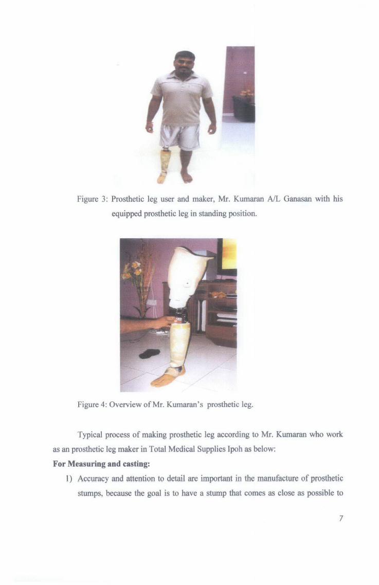
Figure 3: Prosthetic leg user and maker, Mr. Kumaran AIL Ganasan with his
equipped prosthetic leg in standing position.
Figure 4: Overview of Mr. Kumaran's prosthetic leg.
Typical process of making prosthetic leg according to Mr. Kumaran who work
as an prosthetic leg maker in Total Medical Supplies lpoh as below:
For Measuring and casting:
1) Accuracy and attention to det&il are important in the manufacture of prosthetic
stumps, because the goal is to have a stump that comes as close as possible to
7

being as comfortable and useful as a natural one. Before work on the fabrication
of the stump is begun, the prosthetist evaluates the amputee and takes an
impression or digital reading of the residual stump.
2) The prosthetist then measures the lengths of relevant body segments and
determines the location of bones and tendons in the remaining part of the stump.
Using the impression and the measurements, the prosthetist then makes a plaster
cast of the stump. This is most commonly made of plaster of paris, because it
dries fast and yields a detailed impression. From the plaster cast, a positive
model, an exact duplicate of the stump is created.
For Making the socket:
3) Next, a sheet of clear thermoplastic is heated in a large oven and then vacuum
formed around the positive mold. In this process, the heated sheet is simply laid
over the top of the mold in a vacuum chamber. If necessary, the sheet is heated
again. Then, the air between the sheet and the mold is sucked out of the
chamber, collapsing the sheet around the mold and forcing it into the exact
shape of the mold. This thermoplastic sheet is now the test socket; it is
transparent so that the prosthetist can check the fit.
4) Before the permanent socket is made, the prosthetist works with the patient to
ensure that the test socket fits properly. In the case of a missing leg, the patient
walks while wearing the test socket and the prosthetist studies the gait. The
patient is also asked to explain how the fit feels; comfort comes first. The test
socket is then adjusted according to patient input and retried. Because the
material from which the test socket is made is thermoplastic, it can be reheated
to make minor adjustments in shape. The patient can also be fitted with thicker
socks for a more comfortable fit.
5) The permanent socket is then formed. Since it is usually made of polypropylene,
it can be vacuum-formed over a mold in the same way as the test socket. It is
common for the stump to shrink after surgery, stabilizing approximately a year
later. Thus, the socket is usually replaced at that time, and thereafter when
anatomical changes necessitate a change.
8
For fabrication of the prosthetic leg:
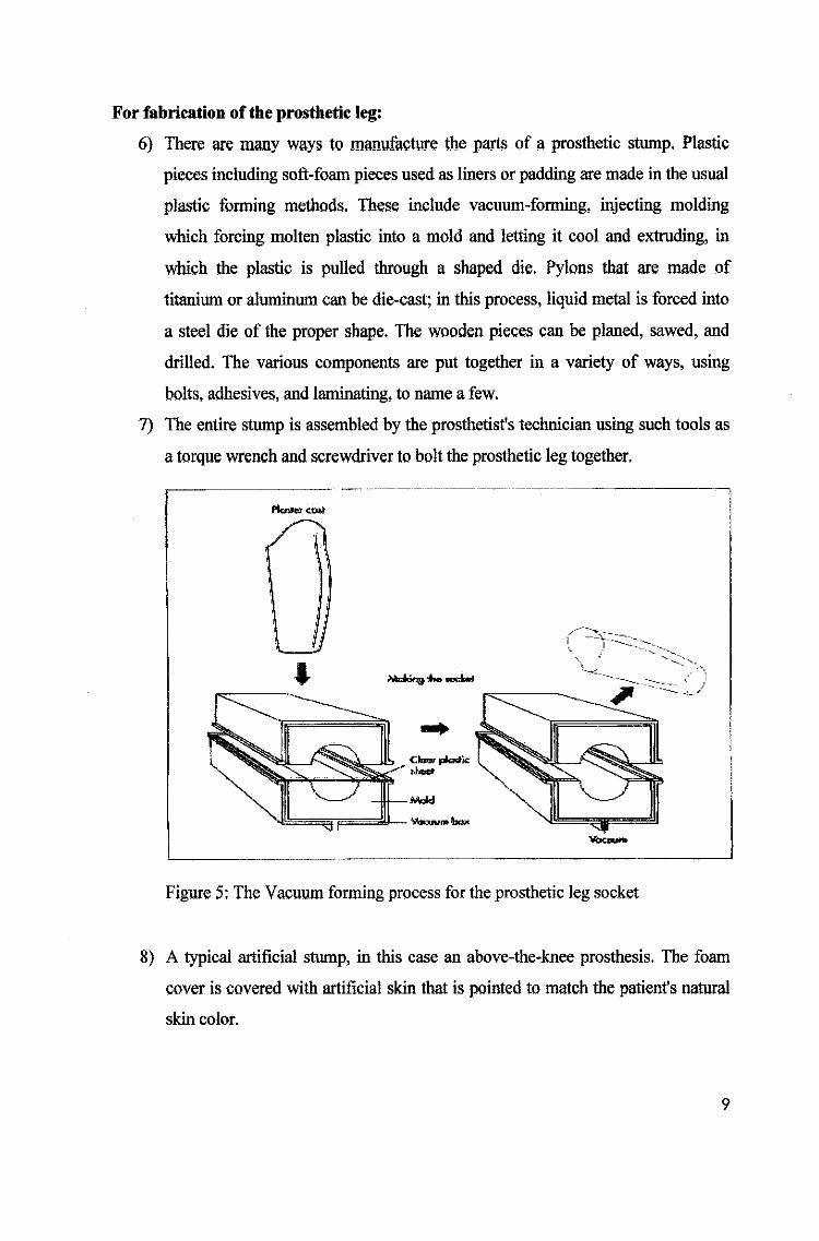
6) There Me many ways to manufacture the p!!rts of a prosthetic stump. Plastic
pieces including soft-foam pieces used as liners or padding are made in the usual
plastic forming methods. These include vacuum-forming, injecting molding
which forcing molten plastic into a mold and letting it cool and extruding, in
which the plastic is pulled through a shaped die. Pylons that are made of
titanium or aluminum can be die-cast; in this process, liquid metal is forced into
a steel die of the proper shape. The wooden pieces can be planed, sawed, and
drilled. The various components are put together in a variety of ways, using
bolts, adhesives, and laminating, to name a few.
7) The entire stump is assembled by the prosthetist's technician using such tools as
a torque wrench and screwdriver to bolt the prosthetic leg together.
• c-·:_-:_]~-:.==::_: ·:~ .. -~.~
........, ,., --.loot \, __ ,· ~ __ -: ,: )
~--~ -----v
--Figure 5: The Vacuum forming process for the prosthetic leg socket
8) A typical artificial stump, in this case an above-the-knee prosthesis. The foam
cover is covered with artificial skin that is pointed to match the patient's natural
skin color.
9

9) Prosthetic device together. After this, the prosthetist again fits the pennanent
socket to the patient, this time with the completed custom-made stump attached.
Final adjustments are then made.
foam (Oiter
I -- 'y\or .
. 1
-\ --'-·J
Figure 6: The above knee prosthetic leg ready cover with the foam cover.
2.13 Case Study-The Jaipur Foot
The Jaipu:r foot case study which done by Nothing About Us Without Us,
Developing Innovative Technologies For, By and With Disabled Persons by David
Werner. The Jaipur Foot, now world famous, was developed by an orthopedic surgeon,
Dr. P.K. Sethi in India. Dr. Sethi developed a design that was more suited to the
traditions, poverty, and enviromnent of rural India. The Jaipur foot-piece is heat-molded
in iron fonns in which pieces of wood are covered with vulcanized rubber. It is very
flexible, water-proof, and looks real with toes, veins, and skin color. The foot is fixed to
a lightweight aluminum shank crafted by traditional tinsmiths. The above-the-knee
stump has a swivel knee joint that pennits comfortable squatting and cross-legged
sitting. Beside that, the Jaipur foot is so practical and low-cost. [ 6]
10
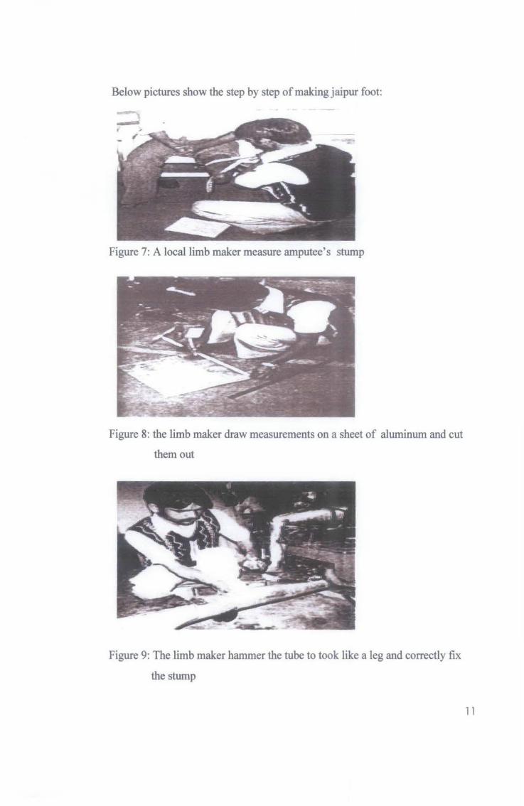
Below pictures show the step by step of making jaipur foot:
Figure 7: A local limb maker measure amputee's stump
Figure 8: the limb maker draw measurements on a sheet of aluminum and cut
them out
Figure 9: The limb maker hammer the tube to took like a leg and correctly fix
the stump
11

Figure 1 0: After adding the foot to the tube, the limb maker add padding and a
strap and try it on amputee's leg.
Figure 11: The amputee walk with the Jaipur limb
2.2 Rapid Prototyping
Rapid prototyping (RP) is a relatively new class of technology used for building
physical models and prototype parts from 3D computer-aided design (CAD) data. Rapid
Prototyping is Computer Controlled Additive Fabrication. Unlike CNC machines tools,
which are subtractive in nature, RP systems join together liquid, powder and sheet
materials to form complex parts.
12

Rapid prototyping able to reduce the prosthetic leg manufacturing process cycle
time compare with the typical manufacturing process by using the injection molding,
vacuum forming and die casting. Beside that, Rapid prototyping is freeform fabrication
where rapid prototyping is largely 'geometrically independent' in that any increase in
the complexity of form does not necessarily make it more difficult to build. [7]
Beside that, by using rapid prototyping, low volume of mass production able to
manufactured in lower price compare with others conventional manufacturing process
such as injection molding and die casting which required expertise and high tooling cost.
The general advantages of using rapid prototype are:
);> Time Compression
Jo> Reduce cost of design iterations
Jo> Addictive Process
);> Minimal human intervention
Jo> Complex intricate geometric forms
Jo> Simultaneous fabrication of multiple parts into a single assembly
Jo> Multiple materials or composite materials in the same part
2.21 Rapid Prototype Machine- 3D Thermo jet 88
The 3D Thermojet 88 rapid prototype machine able to quickly produce superior
quality, low-cost models and evaluate design alternatives. It also able to deliver
improved products to market and reduce product development cycle time and costs.
30 Thermojet 88 Machine Specification:
Technology Multi-Jet Modeling (MJM)
Resolution 300DPI
Maximum Model Size 250mm X 190mm X 200mm (10 X 7.5 X 8 in)
Modeling Material Thermolet 88 Thermopolymer
Material Color option Neutral, Grey or Black
Material Capacity 5.9kg (13 !b)
Material Loading 2.3kg cartridge (5 lb)
13

Interface Ethernet 10/100 Base-TX, RJ-45 Cable, TCP!lP
protocol
Platform Support Silicon Graphics IRIX v6.5.2, Hewlett Packard HP-UX
v10.2 ACE, Sun Microsystems Solaris v2.6.0, IBM RS
6000 AIX v4.3.2, Windows NT v4.0
Power Consumption 230 V AC, 50/60 Hz, 6.3 amps
Dimension W1.37 x D0.76 x H1.12 m (W54 x D30 x H44 in)
Table 1: SpecificatiOn of the 3D Thermojet 88 raptd prototype machine
2.3 Reverse Engineering
Reverse engineering is important in the process of making customizing socket
for the prosthetic leg. Generally, reverse engineering involves producing 3-D images of
manufactured parts when a blueprint is not available in order to remanufacture the part.
To reverse engineer a part, the part is scan with the 3D digitizer machine such as 3D
Thermojet 88 or measured by a coordinate measuring machine (CMM). As it is
measured, a 3-D wire frame image is generated and displayed on a monitor and it is
called the 3D point cloud data. After the measuring is complete, the wire frame image is
dimensioned. Any part can be reverse engineered using these methods. By implemented
the reverse engineering in the process of making the socket of the prosthetic leg, the
process manufacturing cycle time can be reduced compare with conventional
manufacturing process.
2.31 3D Digitizer-Renishaw Cyclone Digitizer
Renishaw's Cyclone Digitizer machine provides a complete stand-alone system
for users who require the ultimate in high speed and fine detail scanning. It can be
supplied with a low-force analogue contact probe for the very best accuracy or with a
non-contact laser probe for scanning delicate materials. The Cyclone system is designed
for users who require the ultimate in high speed or fine detail scanning.
The advantage of using the Renishaw's Cyclone Digitizer are:
);> High speed scamting reduces lead times from pattern to finished part.
14

};> Available with both contact and non-contact (Laser) scanning probes.
)' Quiet and clean in operation - allows installation in an office-like environment.
For setting data capture parameters, data manipulation and machining the Cyclone
system includes Tracecut. This powerful software enables you to machine parts totally
independently of the scanning strategy and the probe styli which were used.
Figure 12: Mechanical probe Figure 13: Laser probe
3D Digitizer Renishaw Cyclone Digitizer Machine Specification:
Length 1273 mm
Width 966mm
Height 2113 mm
Weight 162 kg
Principal application High speed digitizing and fine detail scanning
Axis travels 600 X 500 X 370 nun (23.6 X 19.7 X 14.6 in)
Max. work piece weight 200 kg (441 lb)
Repeatability 5 ~m (0.0002 in)
Axis resolution 1 ~m (0.00004 in)
15
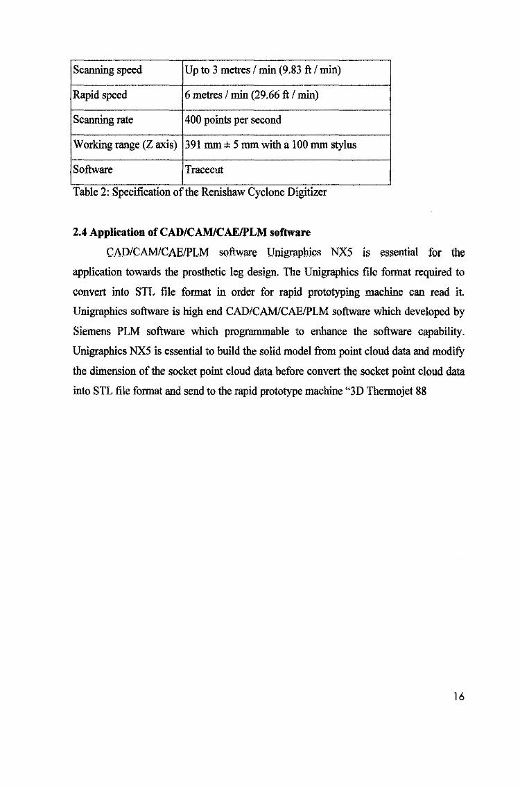
Scanning speed Up to 3 metres I min (9.83 ft I min)
Rapid speed 6 metres I min (29.66 ft I min)
Scanning rate 400 points per second
Working range (Z axis) 391 mm ± 5 mm with a 100 mm stylus
Software Tracecut - ...
Table 2: Spec!ficatton of the Rerushaw Cyclone Dtgttizer
2.4 Application of CAD/CAM/CAE/PLM software
CADICAM/CAE/PLM software Unigraphics NXS is essential for the
application towards the prosthetic leg design. The Unigraphics file format required to
convert into STL file format in order for rapid prototyping machine can read it.
Unigraphics software is high end CADICAM/CAE/PLM software which developed by
Siemens PLM software which programmable to enhance the software capability.
Unigraphics NX5 is essential to build the solid model from point cloud data and modifY
the dimension of the socket point cloud data before convert the socket point cloud data
into STL file format and send to the rapid prototype machine "3D Thermojet 88
16

3.1 Identify the Problems
CHAPTER3
METHODOLOGY
3.11 Limitation of the Renisbaw Cyclone Digitizer
The Renishaw Cyclone Digitizer got limitation of scanning the deep dimension for
generated the 3D point cloud data. Due to the specimen of the amputee mold have a
deep hollow this may make the Renishaw Cyclone Digitizer mechanical probe having
limitation to scan the hollow dimension of the mold. The available length of the
mechanical probe in UTP is from 2cm till the highest to 6cm. But the major limitation
for this mechanical probe is the width of the body of the mechanical probe which got
limitation in using for scanning the hollow dimension. For instance, in scanning the
mold of the amputee, before the mechanical probe able to scan the deepest of the hollow
of the amputee mold, the body of the mechanical probe already touch the side surface of
the hollow before reach the deepest hollow of the amputee mold.
Figure 14: Overview of the mechanical probe.
Beside of the limitation of the mechanical probe, the 3D laser probe also got its'
limitation. Where the 3D laser probe need to be at least 3cm distance from the specimen
17

in order to get the good quality of the 3D surface scanning result. Thus, if the specimen
got deep hollow shape, the scanning 3D surface quality may not in good quality and not
clear enough for the deep surface.
~~~~l()m ~ sp•::...... Figure 15: Overview of the laser probe
Beside that, no angle probe is available in UTP, thus the probe only can be digitizer in
90°. Thus if the specimen have deep dimension and various shape it will make the
process of scanning more difficulty.
3.12 Limitation of the Rapid Prototype Machine (3D Thermojet Printer)
The Rapid Prototype machine which available in UTP has limitation in produce the
maximum size of the product. The maximum size which the 3D Therrnojet Printer can
produce is 250mm X 190mm X 200mm (10 X 7.5 X 8 in). For this project, the
dimension of the positive mold is 31 OmmX 235mm X180mm, due to the length of the
mold is 31cm and biggest diameter of the hollow reach 23cm. Therefore, the 3D
Thennojet Printer will not able to produce the whole prosthetic socket of this project in
one time due to the maximum limitation of the size. Beside that, due to the final product
is in wax form, thus in order to produce the exact prosthetic leg socket which is in
plastic form, rapid tooling is needed.
18

3.2 Learning and familiarize with Renishaw Cyclone Digitizer, Unigraphies, and
3D Tbermojet Printer.
In order to proceed and completed this project, these equipment and software should be
well learned and expertise.
3.3 Mold the stump by using Plaster of Paris
First step to start the project is to find an amputee which is willing to be taken as
the reference for the prosthetic leg. Where a mold or cast will be molded according to
the amputee stump. The mold will be done by using the Plaster of Paris to bandage the
area of the stump. Before the mold is carried out, an exact dimension of the stump will
be carefully measure and record. Then the wet bandages of the Plaster of Paris will be
rolled over the stump. After finish rolled over the stump will be leave the Plaster of
Paris to be hardened to be the mold of the stump. This is called the testing mold socket.
In this project, the writer has invited Mr. Kumaran A/L Ganasan whom has lost his right
leg in an accident occur in June 2003 and currently is a prosthetic leg user to join this
project. Mr. Kumaran is categorized as the above knew prosthetic leg user.
Process of molding the stump are describe as below:
Material needed are:
a) Wrist measurement tape (To measure the stump dimension)
b) 2 bags of Plaster of Paris (each bag dimension15cmX 2.7m) (To make
negative mold of the stump)
c) Colour pencil (To mark the location of the bone on the POP mold)
1) Measurement of the stump by using the wrist tape
For fabrication of the socket, the measurements of the stump are recorded. The
amputee is made to stand as comfortably as possible with support of a parallel bar or a
chair. Stump length is measured from the perineum to the end of the stump, along the
long axis of the femur. With the measuring tape still held from the perineum to the end
of the stump, the medial side of the stump is marked at 2" intervals. The circumference
and length of the stump are recorded; upper circumference of stump is measured at the
level of perineum. Care is taken to ensure that too much tension is not applied on the
measuring tape and that it is kept horizontal as viewed from front and perpendicular to
19

the long axis of the stump as viewed from the side. The lower circumference of the
stump is similarly measured at the lower end of stump. Length of the stump is measured
starting from the upper end of the greater trochanter along the long axis of the femur up
to the lower end of stump.
Figure 16: Measurement of the amputee stump using wrist measurement tape
Here plaster of Paris has been used because of many advantages.
The advantages offered by plaster of Paris over wood and other materials are:-
~ Accuracy: Original patterns, models and molds can be made to extremely close
tolerance.
~ Dimensional stability: Molds are unaffected by normal change in temperature
and humidity and therefore will not shrink and warp.
~ Economy: It is characterized by substantial savings in time because of its
simplicity.
~ Adaptability : Plaster of Paris patterns are adaptable to complex contours and
intersections of both original patterns and models and also in the reproduction of
molds having irregular and intricate shapes.
2) Wrapping of Plaster of Paris:
Following this a negative plaster mold of the stump is taken. To ensure that the socket
will be of correct size, it is best to take the measurements early in the morning as soon
as patient arises. If the amputee is already using a prosthesis he should take it off just
20

before the procedure of taking plaster mold starts. If he is not using any prosthesis, then
he should come with the stump correctly wrapped. For this project taking the plaster
impression of the stump, 2 bags of Plaster of Paris with each dimension 15cm X 2. 7m
was used to wrapped on Mr. Kumaran above knee stump. The Plaster of Paris need to
wet in the water before wrapped on the amputee stump. Figure 8 below show the way of
wrapping the above knee method.
Figure 17: The method of wrapped the above knee stump
Figure 18: 2 bags of Plaster of Paris (Each dimensionl7cmX2.lm)
21

knee of the stump
3) Left for 3-4 minutes to harden the mold
After completed wrapped the above knee of the stump, the Plaster of Paris is left to be
hard for few minutes. During this time, the amputee is not allowed to move to prevent
any error of the mold dimension.
4) Taken out the negative mold
After the Plaster of Paris which wrapped on the amputee stump harden, the negative
mold of the stump is finally mold out. The location of the bone is being mark with color
pencil. The negative mold then is being taken out slowly and carefully to avoid the
dimension of the mold being enlarge and to prevent the negative mold broken.
Figure 20: The Final negative mold of the stump
22
6) Filled the negative mold with cement powder to mold out the positive mold
In order to get the exact dimension and shape of the above knee know dimension from
the negative mold. The negative mold is being filled with cement with a wood stick
insert in it to have the positive mold. The cement is then being left to be hardened. After
the cement been harden, the negative mold is being cut in order to take out the positive
mold to be use to digitized with the Renishaw Cyclone digitizer.
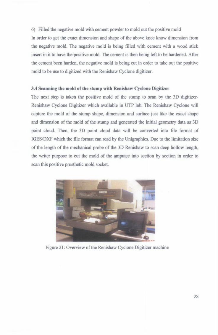
3.4 Scanning the mold of the stump with Renishaw Cyclone Digitizer
The next step is taken the positive mold of the stump to scan by the 3D digitizer
Renishaw Cyclone Digitizer which available in UTP lab. The Renishaw Cyclone will
capture the mold of the stump shape, dimension and surface just like the exact shape
and dimension of the mold of the stump and generated the initial geometry data as 3D
point cloud. Then, the 3D point cloud data will be converted into ftle format of
IGES/DXF which the file format can read by the Unigraphics. Due to the limitation size
of the length of the mechanical probe of the 3D Renishaw to scan deep hollow length,
the writer purpose to cut the mold of the amputee into section by section in order to
scan this positive prosthetic mold socket.
Figure 21: Overview of the Renishaw Cyclone Digitizer machine
23

Figure 22: The amputee mold is cut into 4 sections to overcome the limitation of
the 3D Reninshaw digitizer
prui J
Figure 23: The amputee mold cut into 4 sections.
24

The operation of the Renishaw Cyclone Digitizer as below:
The item to be scanned is secured on the work table to prevent moving during scanning
process.
For 2fi scanning process:
I. Select program > trace cut > 2D Scanning process
2. Job datum > set size probe > initialize machine
Depending on the probe sized that is currently used, the data of probe type, its
diameter and length is input. This will then be compared to the result derived
from the machine's calibrating block where it will estimate the diameter.
3. Set X, Y and Z datum plane
This step is to tell the machine on where the workpiece is placed on the work
table. The probe is moved by bare hand to the nearest location of the workpiece.
This step will set the X, Y and Z datum for the positive mold.
4. Select 2D profile operation> capture> create> job
5. Set profile parameters> SI or metric unit
6. Set initial direction > positive or negative
This step will tell the machine on the direction that the probe will take initially
7. Scanning speed > 1000 to 15000
This step is to set the speed of the probe movement
8. Receive > display graphic to display the scanned images
For 3D scanning process:
1. Ch!Ul_ge the probe with the laser Probe.
2. Select 3D Scanning profile
3. 3D surface> capture> create> jog> ok
4. Laser probe calibration> 3D> Initialize machine
5. Profile> job> save
6. Generate 3D > Capture >Receive > estimate time
The machine can estimate the completion job time where the machine can be
left unattended.
25

3.5 Customize and correcting the 3D cloud point data of the positive mold
Customizing and correcting the 30 cloud point data of the positive mold is done
by using CAD/CAM/CAE/PLM software-Unigraphics NX5. After the positive mold of
the amputee leg has been scanned with 30 Digitizer, the 3D point cloud data is obtained.
The 3D point cloud data will be converted to IGES/DXF file format in order for the
Unigraphics to read. Due to current rapid prototype machine which available in UTP
have the limitation of maximum dimension work piece produce up to 250mm X 190mm
X 200mm (10 X 7.5 X 8 in) only thus research and survey has been done on how to
solve the limitation of the product size which product by the current rapid prototype
machine which available in UTP to produce largest part. Unigraphics is the solution in
order to solve this problem. After the Renishaw Cyclone Digitizer produce the 3D point
cloud data in IGES/DXF file format. Unigraphics then is used to convert the IGES/DXF
file format into solid model. Besides that due to the amputee mold has been cut into
section thus Unigraphics is using to combine again all the parts together to form the
exact socket which needed later to send to the Rapid Prototype machine. In this section
also Unigraphics is used to fix, repair and customize the require dimension of the
product which is needed and convert into STL file format to suit with the current rapid
prototype machine which available in UTP to produce the require product.
STL files are format models made up of triangles (facets). Figure below showed
the format a good and bad STL model is created.
Good STL BadSTL
Figure 24: Comparison of good STL and bad STL file format
When possible, STL files should be output in Binary format. This will reduce the size
dramatically and make file transfers much faster. The operation in Unigraphic to
convert the current 30 point cloud data into STL file format as below:
26
1) File > Export > Rapid Proto typing
2) Set Output type to Binary
3) Set Triangle Tolerance to 0.0025
4) Set Adjacency Tolerance to 0.12
5) Set Auto Normal Gen to On
6) Set Normal Display to Off
7) Set Triangle Display to On
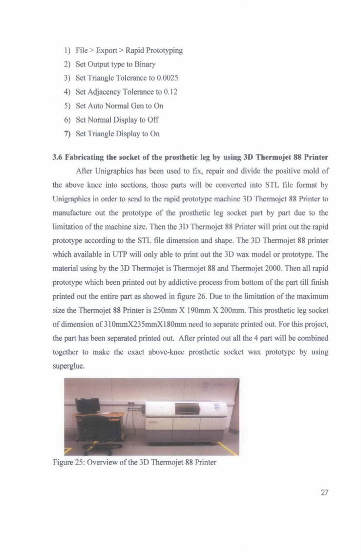
3.6 Fabricating the socket of the prosthetic leg by using 3D Thermo jet 88 Printer
After Unigraphics has been used to fix, repair and divide the positive mold of
the above knee into sections, those parts will be converted into STL file format by
Unigraphics in order to send to the rapid prototype machine 3D Thermojet 88 Printer to
manufacture out the prototype of the prosthetic leg socket part by part due to the
limitation of the machine size. Then the 3D Thermojet 88 Printer will print out the rapid
prototype according to the STL file dimension and shape. The 3D Thermojet 88 printer
which available in UTP will only able to print out the 30 wax model or prototype. The
material using by the 3D Thermojet is Thermojet 88 and Thermojet 2000. Then all rapid
prototype which been printed out by addictive process from bottom of the part till finish
printed out the entire part as showed in figure 26. Due to the limitation of the maximum
size the Thermojet 88 Printer is 250mm X 190mm X 200mm. This prosthetic leg socket
of dimension of 31 Omm.X235mmX180mm need to separate printed out. For this project,
the part has been separated printed out. After printed out all the 4 part will be combined
together to make the exact above-knee prosthetic socket wax prototype by using
superglue.
Figure 25: Overview of the 30 Thermojet 88 Printer
27

t
'
Figure 26: Addictive process by 3D Thermojet 88 printer
3.7 Rapid Tooling
Rapid tooling will be done after the rapid prototype process in order to make the socket
of the prosthetic leg more realistic by using the thermoplastic or engineering plastic
material. Rapid Tooling is the result of combining Rapid Prototyping techniques with
conventional tooling practices to produce parts of a functional nature from electronic
CAD data in less time and at lower cost relative to traditional machining methods.
Advantages of Rapid Tooling are:
);» Shorten the tool making time
);» Direct transfer of CAD data
);» Functional test of the parts in early design make possible
);» Lowcost
For this project, due to the final part of the prosthetic leg socket is in plastic fonn,
therefore plastic mould or RTV Silicon Rubber Mould is used to produce the final
plastic parts.
3.8 Testing
The socket of the prototype will be tested by amputee in order to make sure the
prototype able to work functional and able to fit the patient leg.
28
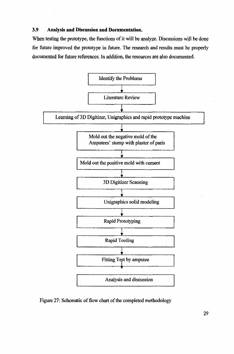
3.9 Analysis and Discussion and Documentation.
When testing the prototype, the functions of it will be analy?;e. Discussions will be done
for future improved the prototype in future. The research and results must be properly
documented for future references. In addition, the resources are also documented.
IdentifY the Problems
J Literature Review I
~ L . f3D D' . . U . hi d 'd bin earrung o .. tgtttzer, mgrap cs an. rapt prototype mac . e
~ Mold out the negative mold of the Amputees' stump with plaster of paris
~ Mold out the positive mold with cement
~ 3D Digitizer Scanning
~ Unigraphics solid modeling
~ Rapid Prototyping
~ Rapid Tooling
-----·- ~- -- ·- ..
~ Fitting TeFt by amputee
•
Analysis and discussion
Figure 27: Schematic of flow chart of the completed methodology
29
CHAPTER4
RESULT AND DISCUSSION
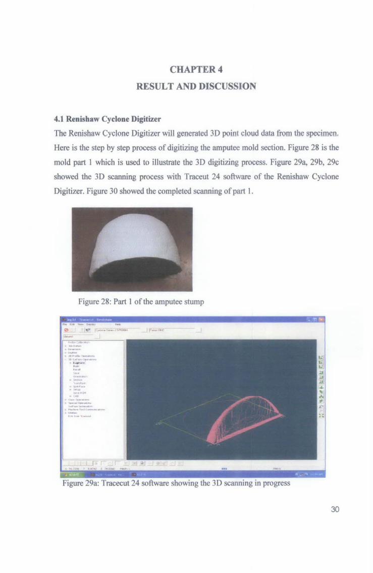
4.1 Renishaw Cyclone Digitizer
The Renishaw Cyclone Digitizer will generated 3D point cloud data from the specimen.
Here is the step by step process of digitizing the amputee mold section. Figure 28 is the
mold part 1 which is used to illustrate the 30 digitizing process. Figure 29a, 29b, 29c
showed the 3D scanning process with Traceut 24 software of the Renishaw Cyclone
Digitizer. Figure 30 showed the completed scanning of part 1.
Figure 28: Part 1 of the amputee stump
• ~Olllbn . ......,., ·-M • .. r,......,.o..r......., :'T·t.r- ......... ··-.....
So· · ....... _. . ... _ .......,, .
. ~··....... ~ka• . ,.,., . cc---·-• ,_..c...., ... r. ,.,._ ... ,_. ...
Figure 29a: Tracecut 24 software showing the 3D scanning in progress
30

..,_. , ....... , ••• r.-. - - )(l
,..~&Ito ....
. ""';CMl - ...... . .. .., • _ ... ~ c. .,;,. c;.., ..
X:~Z'~~A.A~ . .__ . ..., .,. - .. • .All 11!115;111 ·--
. ,.,.,.! s---
-a<
. ~ ·-- -- ').. - ·~ ,.,. ..... -~ ,vr""-"-' ~ .. ft:J'Y
• e••• t.lfiiiQ-t.'t-,..,
•niadll
~-· -. . . :; .. ,., .. ~ . ~--
Figure 29b: Tracecut 24 software showing the 3D scanning in progress
-·· •• ,. ~-~~- .. T- ~
Figure 29c: Tracecut 24 software showing the 3D scanning in progress
31
.. _ .. ; .. ,.-\,, .. ,.. ,._ . ,... ~
c;-;:---
..... ~.-·r~
·~·l.r ......
·~·' ~ ·~--~· ... · ~·"""" l ..-rll'O if,.,....•l
·~-·\-•) t .... · ..-..a. .. , .... IIIMiel&l'.. ,. .....
'-""'"" ..... ,._....) .__"' " ..... , '""' .._ ..... .__ . ..-SUIIIIA"t
0
I . - J • . - . "' • -,. '- "'
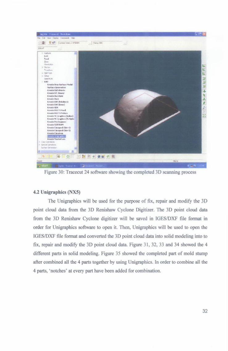
Figure 30: Tracecut 24 software showing the completed 3D scanning process
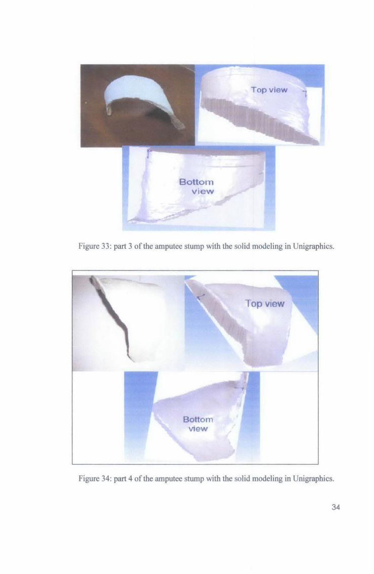
4.2 Unigraphics (NXS)
The Unigraphics will be used for the purpose of fix, repair and modify the 3D
point cloud data from the 3D Renishaw Cyclone Digitizer. The 3D point cloud data
from the 3D Renishaw Cyclone digitizer will be saved in IGES/DXF file format in
order for Unigraphics software to open it. Then, Unigraphics will be used to open the
IGES/DXF file format and converted the 3D point cloud data into solid modeling into to
fix, repair and modify the 3D point cloud data. Figure 31, 32, 33 and 34 showed the 4
different parts in solid modeling. Figure 35 showed the completed part of mold stump
after combined all the 4 parts together by using Unigraphics. In order to combine all the
4 parts, 'notches' at every part have been added for combination.
32

Bottom
view
Top view
_j
Figure 31: part 1 of the amputee stump with the solid modeling in Unigraphlcs.
Bottom view
Top view
Figure 32: part 2 of the amputee stump with the solid modeling in Unigraphlcs.
33
Bottom view
Top view 1
Figure 33: part 3 of the amputee stump with the solid modeling in Unigraphics.
Bottom view
Top view
Figure 34: part 4 of the amputee stump with the solid modeling in Unigraphics.
34

+ + sample of 'notch'
Figure 35: 'Notches' are design at every parts in order to combine all the 4 parts
together.
.----Top view front view back view
Figure 36: The completed part of mold stump after combined all the 4 parts together by
using Unigraphics.
35

4.3 Rapid Prototype
The 3D Thermo jet 88 printer will produce the maximum size of dimension 250mm X
190mm X 200mm. But for this project due to the entire part dimension is
310mmX235mmX180mm, therefore the part also will be separate in to 4 parts to print
out and then combined all the 4 parts together with the 'notches' that are created with
Unigraphics. The process of combining all the 4 parts is easy by using superglue due to
the entire parts is from wax form. Wax can be easy shaped and combined together.
Figure 36: Side view of the completed rapid prototype prosthetic leg socket after
combined with the superglue.
Figure 37: Top view of the completed prototype rapid prototype prosthetic leg socket
after combined with the superglue.
36

4.4 Rapid Tooling
Rl!pid tooling is done for the purpose of having the final product of the prosthetic leg in
plastic form. The process of the rapid tooliog is done as below:
Model preparation
I Frame preparation
I Silicon Rubber Preoaration
I Weight the material
I Degassing process
I Pour the mix
I Vulcanized process
I Split the cure mould
I Pe-mou!d the master oatern
I Prepare the plastic material
I - -·-
Degasses and pour into the RTV
I Final product in plastic form
Figure 38: The schematic diagram of the Rapid Tooliog process flow
37

For this Final year project, after discussing with the writer supervisor and others lecturer
the final part of the prosthetic leg will be scaled down in order to save cost due to every
student is only giving limited budget in order to complete their final year project.
Therefore, the real size of the prosthetic leg socket for this project has been scale down
into 80mmX50mmX45mm in order to show the rapid tooling process. The different
between the final part of the prosthetic leg of the rapid tooling with the rapid prototype
is plastic material which can sustain high strength compare with wax. Therefore, a scale
down of this project is essential to save material cost of the rapid tooling process.
Figure 39: The scale down prosthetic leg in hanging position inside a box prepare for
rapid tooling process.
Figure 40: The fmal plastic part of the prosthetic leg socket after rapid tooling process.
38

CHAPTERS
CONCLUSION
By using 'Customizing Prosthetic Leg Socket by using Rapid Prototype with
Reverse Engineering' method, although the cost of the 3D Thermo jet material is higher
due to new technology but by using this method the tooling cost involved injection
molding and vacuum forming can be excluded Besides that, reverse engineering is
essential when there is no blue print available. 3D Scanning Digitizer machine able to
scan in fine detail with high speed scanning up to 3 meter/s and the Rapid Prototype
machine is time compression and able to produce complex intricate geometric forms
and simultaneous fabrication of multiple parts into a single assembly compare to
injection molding process which need expertise and experience to handle the process of
making the prosthetic leg. Due to the limitation size which Rapid Prototype machine
can be produced therefore Rapid Prototype machine is essential for producing small size
of the part rather than big size of the part. Unigraphics is essential to fix, repair and
customize the 3D point cloud data. Besides, the user may have preference on the
thickness and shape of the prosthetic leg socket by customizing the 3D point cloud data
with Unigraphics. This study concludes that Reverse Engineering and Rapid Prototype
able to produce prosthetic leg socket. In future, prosthetic leg socket manufacturer able
to consider this new method and the traditional method which applicable to them.
39

CHAPTER6
REFERENCES
[1] www.belsurg.org/imgupload/RBSS/wasiak.pdf
[2] http://www4.anny.mil/ocpa/read.php?story _id_key=5784
[3) Allen Ho, Total Medical Supplies, 7 Medan Istana 7, Bandar Ipoh Raya, 30000 Ipoh,
Perak.
[4] Dr. Ravindran, General Surgery Department, General Hospital Ipoh, Jalan Hospital
30990 lpoh, Perak.
[5] Mr. Kumaran AIL Ganasan, Prosthetist from Total Medical Supplies, 7 Medan
Istana 7, Bandar lpoh Raya, 30000 lpoh, Perak.
[6] David Wemer(1998), Nothing about us without us, developing innovative
technologies for, by and with disabled persons, Health Wrights.
[7] Ian Gibson (2005), Advance Manufacturing Technology For Medical Applications,
Wiley.
Others references:
• Journal: Immediate prosthesis fitting and comprehensive rehabilitation
following lower
limb amputation - the most important components of physiotherapy by Aneta
Pirowska,
Tomasz Wloch and Roman Nowobilski (30.12.2005).
• Journal: Prosthetic Leg Design by Daniel Rihs and Ivan Polizzi (2001), from
Victorian University of Technology.
• JAMcDonald, CJRyall and DIWimpenny (2001), Rapid Prototyping Casebook,
Professional Engineering Publishing Limited London and Bury St Edmunds, UK.
• Rafiq Noorani (2006), Rapid Prototyping Principles and Applications, Wiley.
• Teoh Swee Hin (2004), Engineering material biomedical application, World
Scientific.
• Anthony Holms-Walker (2005), Life Enhancing Plastic, imperial college Press.
40

TASKS/WEEK
-Renishaw cyclone digitizer study -CAD/CAM/CAEIPLM software study
-Medical aoolication research
Appendix 1: Gantt Chart for
JAN
suggest Done
l vear Project 1
FEB

JULY AUGUST SEP OCT NOV TASKS/WEEK 1 2 3 4 6 6 7 8 9 10 11 12 13 14 16 16 17
~ Submission of the Progress Report 1
-submitted on 15 AUG 2008
Submission of the Report2
-submitted on 12 "' ber2008
_3. D seaming - completed seaMing the mold (completed)
"'--... - llacllftcatlon -completed fix, repaw and rno<flfy the 30 point cloud
data
Seminar Pl'888ntatlon
- Done on 24 September 2008
Rapkl_ •• -Awaiting lab printing the parts
searching fOr sltcon , _ _, -1 , _ _..,_ ...... I I
~ 100111111 -- Awaiting siliCOn material(material amvec1 20 nov) I Postare II 1 I
-poster .. on 10 oct 2008
Final Oral Pl'888atation
- 25th November 2008
Hardbound dlseertation - suggest milestone
Appendix 1: Gantt Chart for Final Year Project 2