customer technical briefing on ec225 103112.pdf
TRANSCRIPT
Controlled Landing on Water of EC225 (G-CHCN)Incident date: 22 October 2012
Technical Briefing
1. Event Summary Page 2
2. Incident Outline – 22nd October Page 3
3. EC225LP MGB Design Architecture Page 4
4. EC225LP MGB Internal Layout Page 5
5. EC225LP MGB Internal Layout Page 6
6. EC225LP MGB Lubrication System Page 7
7. EC225LP Emergency Lubrication System Pages 8 - 9
8. Super Puma Lubrication System Comparison Page 10
9. Investigation Outcomes after Bond Incident Page 11
10. Bevel Gear Vertical Shaft Pages 12 -14
11. “Shaft 1” vs. “Shaft 2” Page 15
12. Current flight status? Page 16
13. What’s next ? Page 17
Table of Contents
1
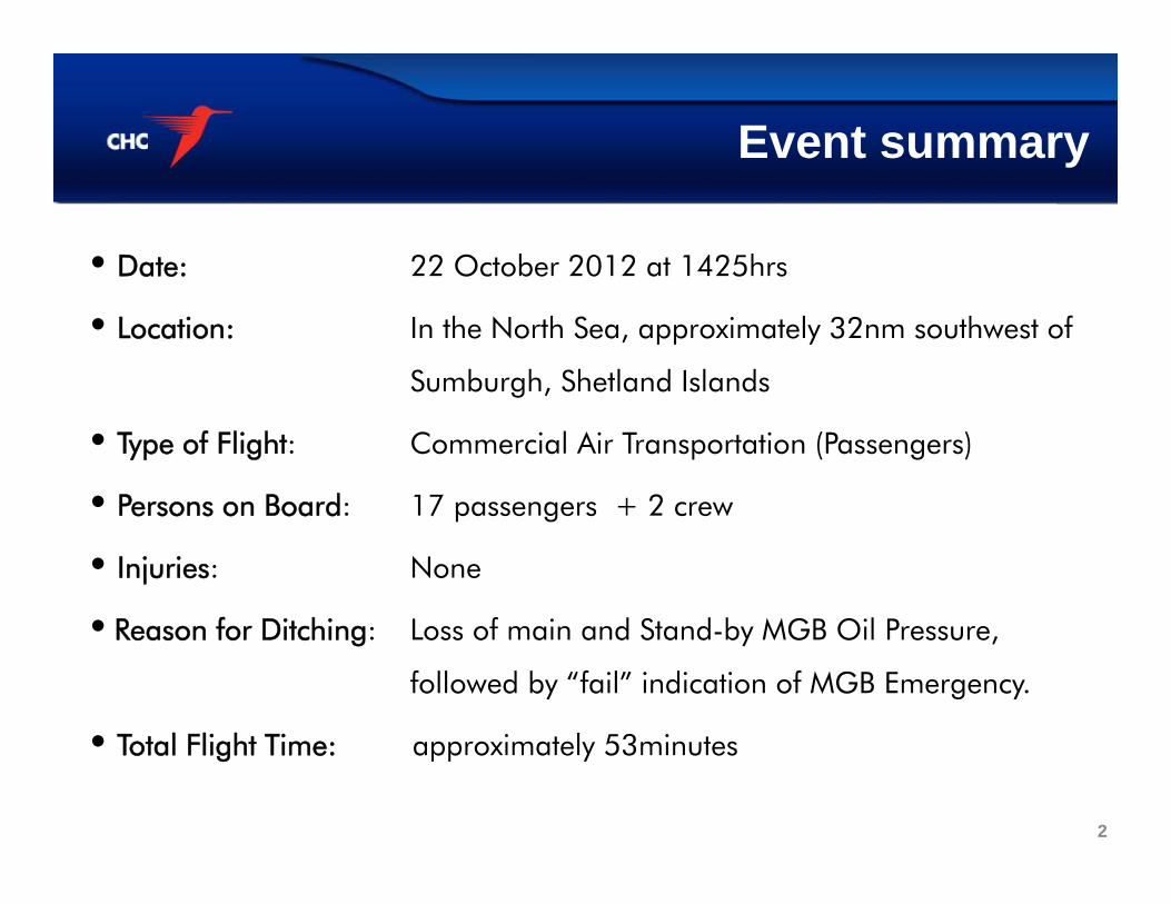
• Date: 22 October 2012 at 1425hrs
• Location: In the North Sea, approximately 32nm southwest of
Sumburgh, Shetland Islands
• Type of Flight: Commercial Air Transportation (Passengers)
• Persons on Board: 17 passengers + 2 crew
• Injuries: None
• Reason for Ditching: Loss of main and Stand-by MGB Oil Pressure,
followed by “fail” indication of MGB Emergency.
• Total Flight Time: approximately 53minutes
Event summary
2
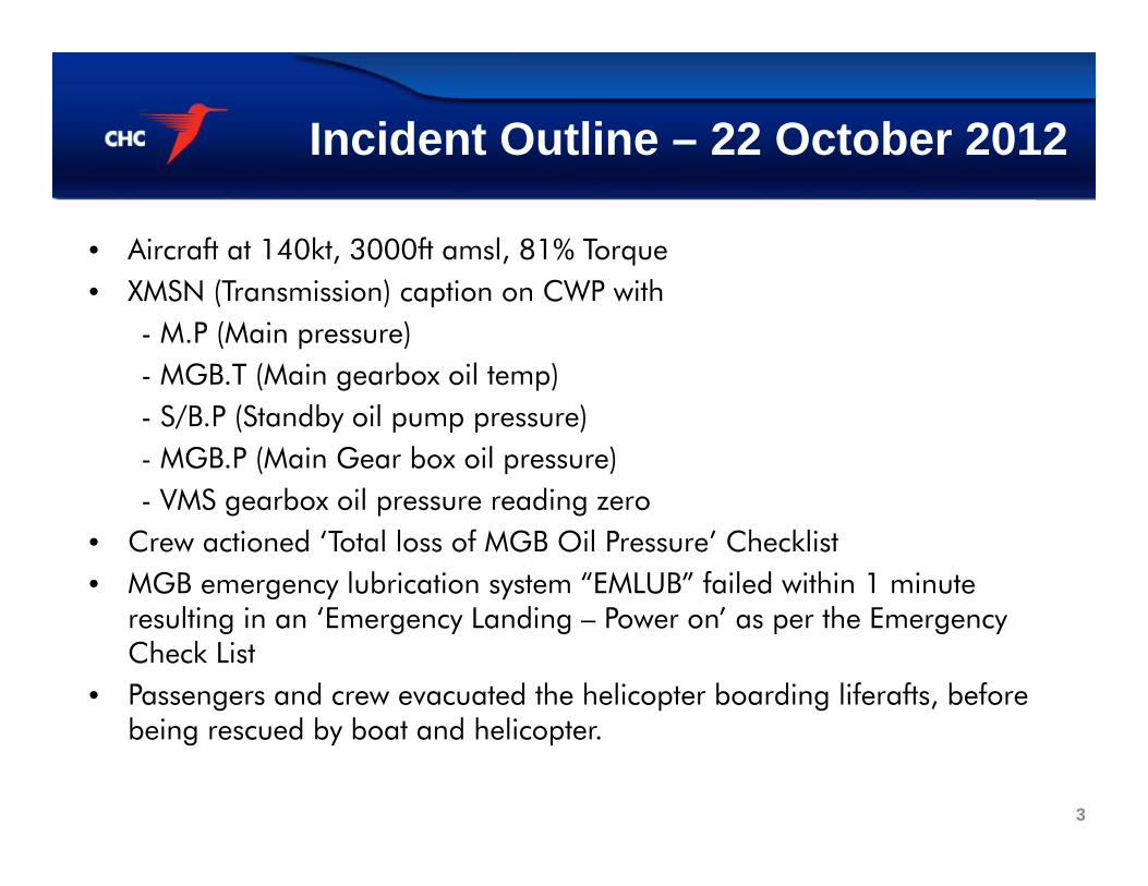
• Aircraft at 140kt, 3000ft amsl, 81% Torque• XMSN (Transmission) caption on CWP with
- M.P (Main pressure)- MGB.T (Main gearbox oil temp)- S/B.P (Standby oil pump pressure)- MGB.P (Main Gear box oil pressure)- VMS gearbox oil pressure reading zero
• Crew actioned ‘Total loss of MGB Oil Pressure’ Checklist• MGB emergency lubrication system “EMLUB” failed within 1 minute
resulting in an ‘Emergency Landing – Power on’ as per the Emergency Check List
• Passengers and crew evacuated the helicopter boarding liferafts, before being rescued by boat and helicopter.
Incident Outline – 22 October 2012
3
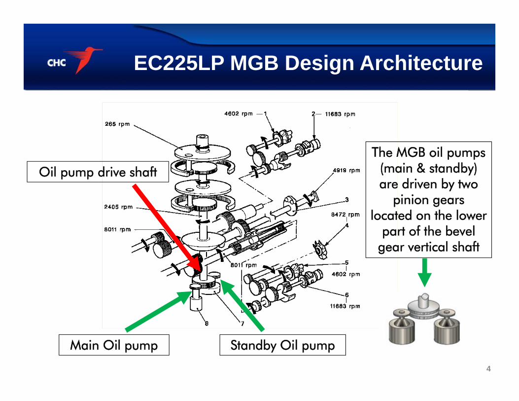
EC225LP MGB Design Architecture
Oil pump drive shaft
Standby Oil pump
The MGB oil pumps (main & standby) are driven by two
pinion gears located on the lower
part of the bevel gear vertical shaft
Main Oil pump
4
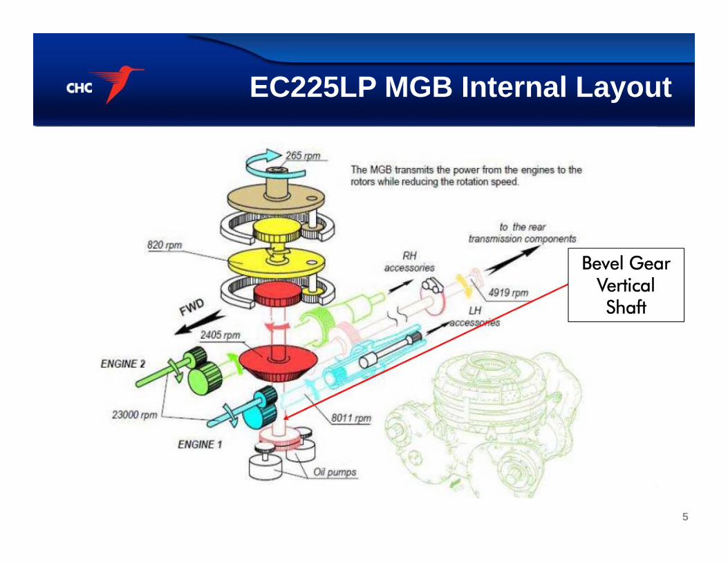
EC225LP MGB Internal Layout
Bevel Gear Vertical Shaft
5
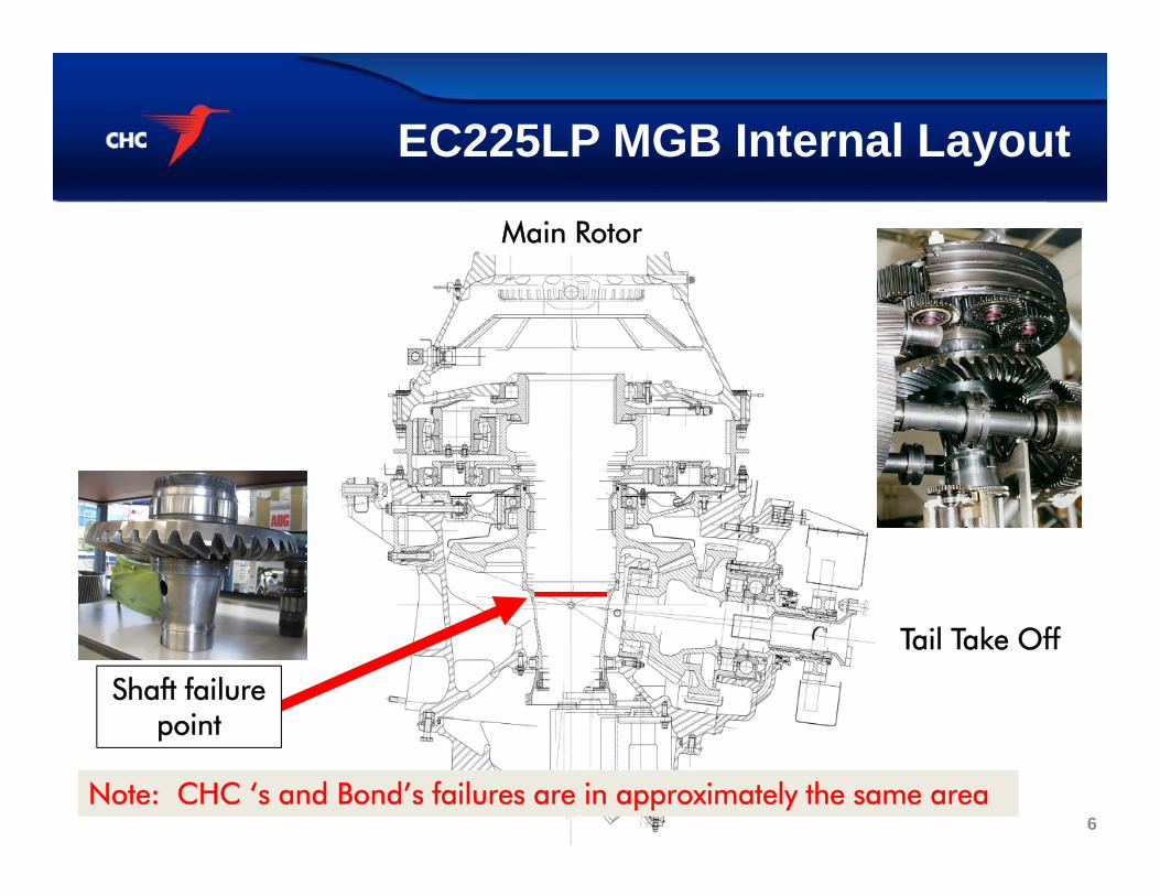
EC225LP MGB Internal Layout
Shaft failure point
Tail Take Off
Main Rotor
Note: CHC ‘s and Bond’s failures are in approximately the same area 6
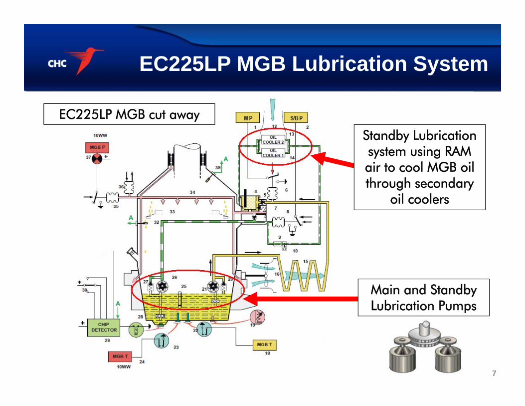
EC225LP MGB Lubrication System
EC225LP MGB cut away
Standby Lubrication system using RAM air to cool MGB oil through secondary
oil coolers
Main and Standby Lubrication Pumps
7
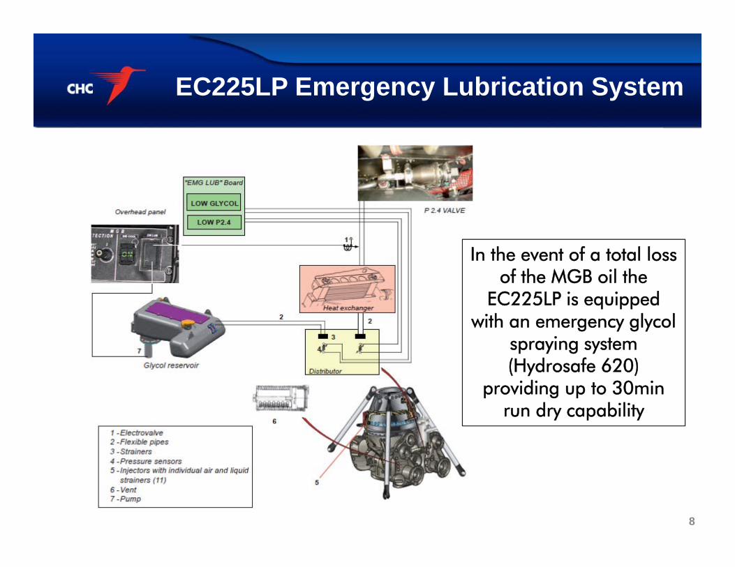
EC225LP Emergency Lubrication System
In the event of a total loss of the MGB oil the
EC225LP is equipped with an emergency glycol
spraying system (Hydrosafe 620)
providing up to 30min run dry capability
8
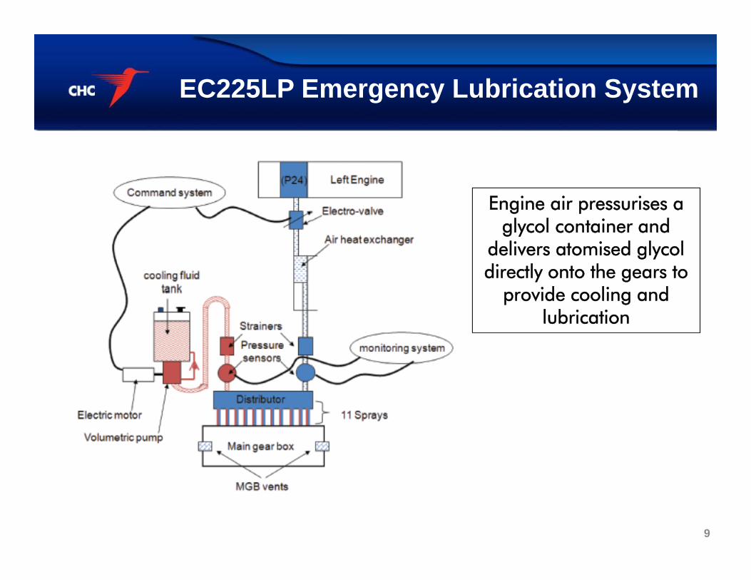
EC225LP Emergency Lubrication System
Engine air pressurises a glycol container and
delivers atomised glycol directly onto the gears to
provide cooling and lubrication
9
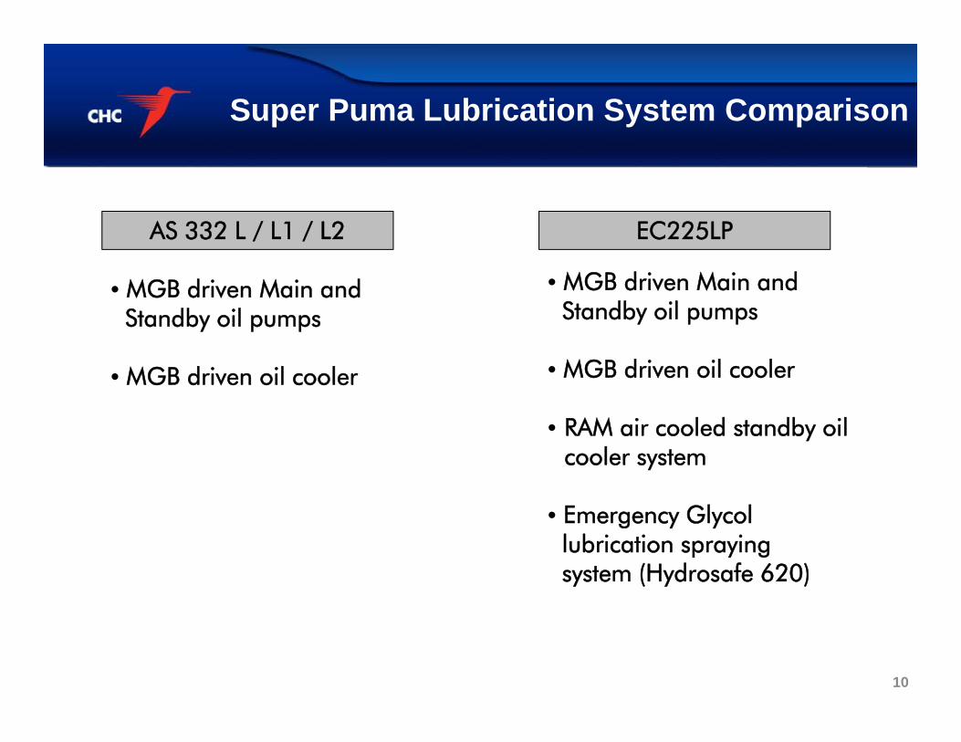
Super Puma Lubrication System Comparison
• MGB driven Main andStandby oil pumps
• MGB driven oil cooler
• MGB driven Main and Standby oil pumps
• MGB driven oil cooler
• RAM air cooled standby oil cooler system
• Emergency Glycol lubrication sprayingsystem (Hydrosafe 620)
AS 332 L / L1 / L2 EC225LP
10
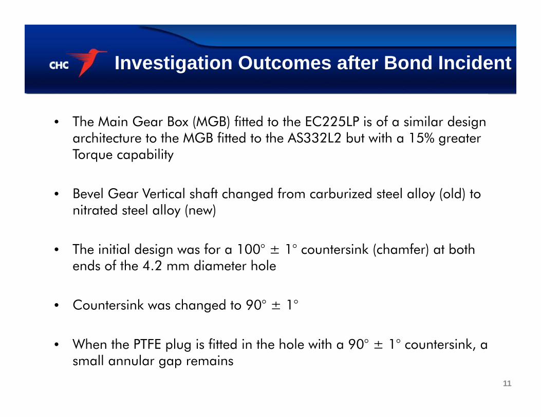
Investigation Outcomes after Bond Incident
• The Main Gear Box (MGB) fitted to the EC225LP is of a similar design architecture to the MGB fitted to the AS332L2 but with a 15% greater Torque capability
• Bevel Gear Vertical shaft changed from carburized steel alloy (old) to nitrated steel alloy (new)
• The initial design was for a 100° ± 1° countersink (chamfer) at both ends of the 4.2 mm diameter hole
• Countersink was changed to 90° ± 1°
• When the PTFE plug is fitted in the hole with a 90° ± 1° countersink, a small annular gap remains
11
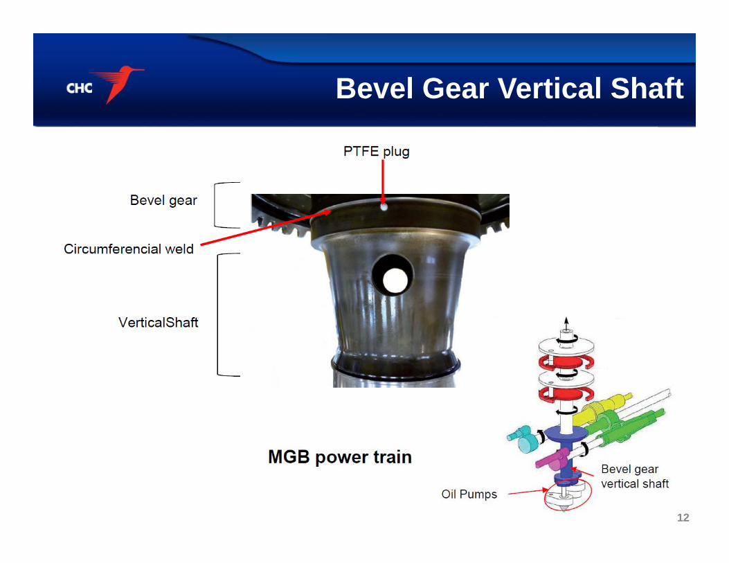
Bevel Gear Vertical Shaft
12
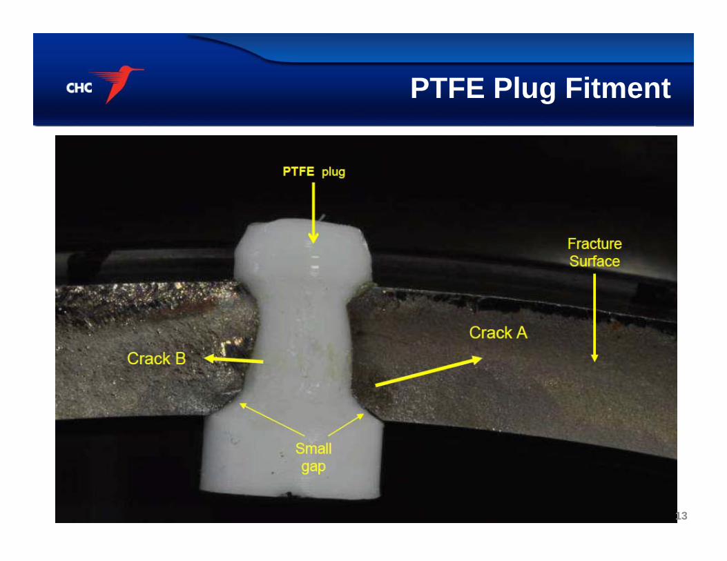
PTFE Plug Fitment
13
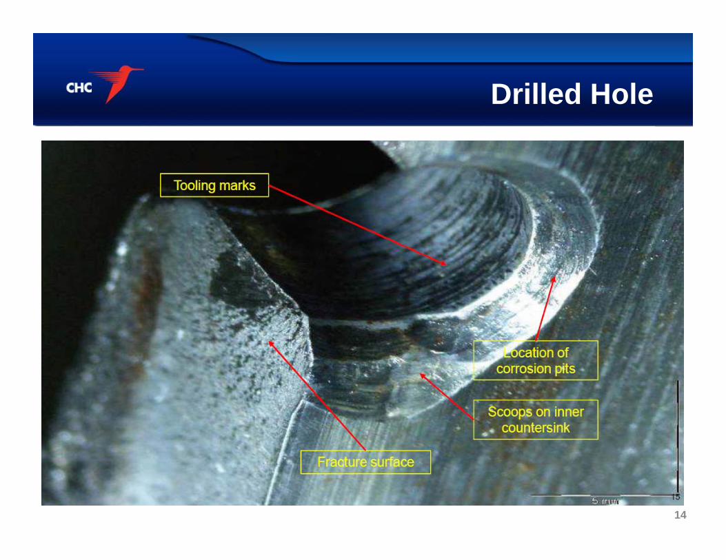
Drilled Hole
14
“Shaft 1” vs. “Shaft 2”
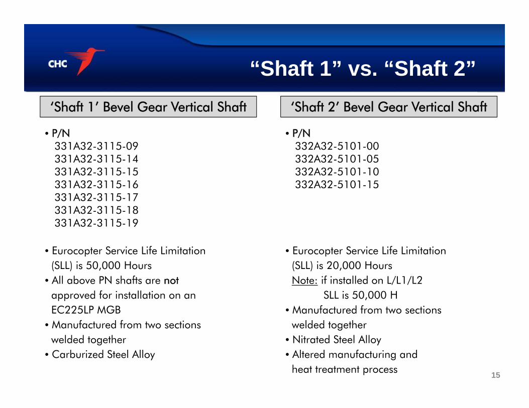
• P/N331A32-3115-09331A32-3115-14331A32-3115-15331A32-3115-16331A32-3115-17331A32-3115-18331A32-3115-19
• Eurocopter Service Life Limitation(SLL) is 50,000 Hours
• All above PN shafts are notapproved for installation on an EC225LP MGB
• Manufactured from two sectionswelded together
• Carburized Steel Alloy
‘Shaft 1’ Bevel Gear Vertical Shaft
• P/N332A32-5101-00332A32-5101-05332A32-5101-10332A32-5101-15
• Eurocopter Service Life Limitation(SLL) is 20,000 HoursNote: if installed on L/L1/L2
SLL is 50,000 H • Manufactured from two sections
welded together• Nitrated Steel Alloy• Altered manufacturing and
heat treatment process
‘Shaft 2’ Bevel Gear Vertical Shaft
15
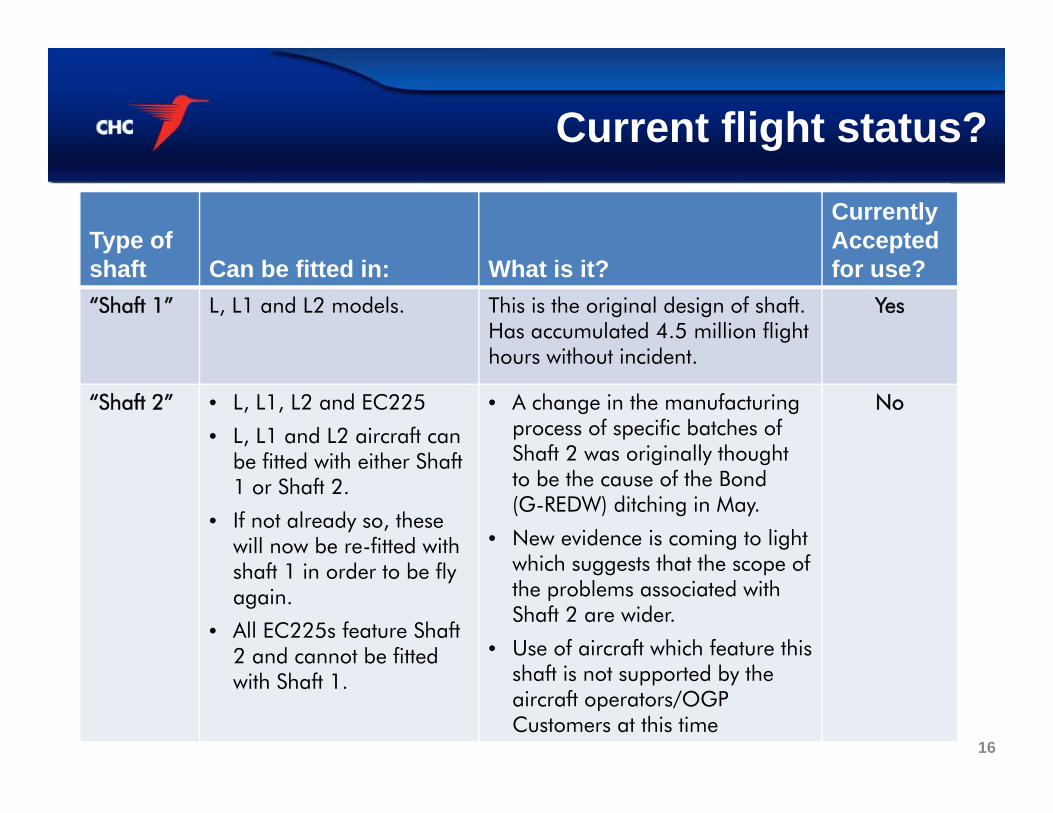
Current flight status?
Type of shaft Can be fitted in: What is it?
Currently Accepted for use?
“Shaft 1” L, L1 and L2 models. This is the original design of shaft. Has accumulated 4.5 million flight hours without incident.
Yes
“Shaft 2” • L, L1, L2 and EC225
• L, L1 and L2 aircraft can be fitted with either Shaft 1 or Shaft 2.
• If not already so, these will now be re-fitted with shaft 1 in order to be fly again.
• All EC225s feature Shaft 2 and cannot be fitted with Shaft 1.
• A change in the manufacturing process of specific batches of Shaft 2 was originally thought to be the cause of the Bond(G-REDW) ditching in May.
• New evidence is coming to light which suggests that the scope of the problems associated withShaft 2 are wider.
• Use of aircraft which feature this shaft is not supported by the aircraft operators/OGP Customers at this time
No
16
What’s next ?• AAIB investigation is on-going
• Aircraft has been disassembled as an important part of the AAIB investigation,augmenting technical data and information from interviews with crew members andpassengers
• Eurocopter is fully cooperating with the investigation and continues to work on a newshaft system
• Eurocopter is also looking at the MBG EMLUB system to prevent a failure indication whenthe system is operating correctly
• Returning the EC225LP to service is still under review and will be discussed in detail withour Customers, Eurocopter, the CAA UK, the European Helicopter Operators Committee(EHOC) and the Helicopter Safety Steering Group (HSSG) - which includes Offshore Oiland Gas companies, helicopter operators and Trade Unions
• As of 1 November, Eurocopter is finalising a detailed presentation of technical and otherrelevant information. Eurocopter is launching a micro site (as part of its main corporatewebsite) where they will host and maintain up-to-date information for customers andmedia – this will go live from 2 November. A link to the site will be shared widely assoon as it is live 17
Questions
• Investigations are ongoing…
• Any Questions …?
Thank you,
CHC Helicopter
18