customer owned and constructed transformer enclosure
TRANSCRIPT
0951-19_rev 1/20
Powering forward. Together.
Customer Owned and Constructed Transformer Enclosure
Engineering Specification T013January 2020
Electric Service Requirements

ENGINEERING
SPECIFICATION
No. T013
page 1 of 13
REV. 2 DATE: 1/2020
CATEGORY
ELECTRIC SERVICE REQUIREMENTS
SUBJECT
CUSTOMER OWNED AND CONSTRUCTED TRANSFORMER ENCLOSURE
TABLE OF CONTENTS
1. PURPOSE ........................................................................................ 2
2. DESIGN ............................................................................................ 3
3. MATERIAL ....................................................................................... 9
4. SUBMITTALS ................................................................................. 11
5. APPROVAL BY OTHER AGENCIES .............................................. 11
6. INSPECTION .................................................................................. 12
7. INSTALLATION .............................................................................. 12
Appendix A: Construction Standards Drawings ................................... 13

ENG. SPEC.
T013
REV.
2
ELECTRIC SERVICE REQUIREMENTS FOR CUSTOMER OWNED AND CONSTRUCTED TRANSFORMER
ENCLOSURE
Page 2
of 13
1. PURPOSE
The purpose of this specification is to outline SMUD’s electrical service requirements and construction standards for a building enclosure used to house
one or more utility owned transformers, switching cubicles and/or associated secondary boxes. The enclosure shall be provided complete with all conduit, wells, pads, boxes, walls, and fences as specified.
The installation of the power cable is not a part of this specification.
The customer shall furnish all materials, labor, equipment, and incidentals necessary to provide a complete building enclosure ready for the placement of utility equipment.
1.1. Standards
All equipment shall be designed, manufactured, supplied, and installed in accordance with the latest applicable standards of:
(CFC) California Fire Code (NEMA) National Electric Manufacturers Association (ANSI) American National Standards Institute (ASTM) American Society for Testing and Materials
(IEEE) Institute for Electrical and Electronic Engineers (UL) Underwriter's Laboratory (CEC) California Electrical Code
(CPUC) California Public Utility Commission General Order 128 (NEC) National Electric Code
1.2. Permits and Licenses
Unless noted elsewhere, all permits and licenses necessary for the
prosecution of the work shall be secured by the Customer, at the Customer’s own expense. The Customer shall give all notices necessary and incident to the due and lawful prosecution of the work.

ENG. SPEC.
T013
REV.
2
ELECTRIC SERVICE REQUIREMENTS FOR CUSTOMER OWNED AND CONSTRUCTED TRANSFORMER
ENCLOSURE
Page 3
of 13
2. DESIGN
2.1. General
The requirements specified in this section are intended to provide SMUD with a space to place service equipment in building areas on Customer's property. These requirements meet the operational and safety needs of
SMUD and safeguard people and property from hazards arising f rom the use of such equipment. These requirements are not intended as a complete design specification. Any conflict with these requirements and other applicable codes, ordinances, and standards shall be brought to the
attention of SMUD in writing using the submittal process in section 4.
2.1.1. Any variance requests shall be submitted to SMUD in writing.
2.1.2. The design of the enclosure shall facilitate installation & maintenance of the installed equipment. In the event of transformer failure/replacement, the
customer/owner shall be required to pull the secondary conductors in the clear to enable transformer replacement. SMUD must have 24-hour access to the enclosure.
2.1.3. The enclosure space must conform to all applicable state and local codes, including, but not limited to, fire-suppression, smoke alarms, ventilation, etc.
2.2. Enclosure Options
Customer owned and constructed transformer enclosures shall meet one of the three following general options:
2.2.1. Option 1
2.2.1.1. Meeting Vault requirements as outlined in CEC 450 Part 3
2.2.1.2. 3-hour fire resistance rating for walls, roofs, and floors
2.2.1.3. Solid doors with 3-hour fire resistance rating
2.2.1.4. 6" Minimum removable door sill for fluid containment
2.2.1.5. Ventilation per CEC 450.9/450.45
2.2.1.6. Drainage
2.2.1.7. No SMUD required clearances to openings around enclosure door;
2.2.1.8. SMUD required clearances for installation, operation and maintenance of units
ENG. SPEC.
T013
REV.
2
ELECTRIC SERVICE REQUIREMENTS FOR CUSTOMER OWNED AND CONSTRUCTED TRANSFORMER
ENCLOSURE
Page 4
of 13
2.2.2. Option 2
2.2.2.1. Fire-Suppression System
2.2.2.2. Installation of units with FM rated less-flammable fluids
2.2.2.3. 1-hour fire resistance rating for walls, roofs, and floors
2.2.2.4. Solid doors with 1-hour fire resistance rating
2.2.2.5. 6" minimum removable door sill for fluid containment
2.2.2.6. Ventilation per CEC 450.9/450.45
2.2.2.7. Drainage
2.2.2.8. No SMUD required clearances to openings around enclosure door
2.2.2.9. SMUD required clearances for installation, operation and maintenance of units
2.2.3. Option 3
2.2.3.1. Fire-Suppression System
2.2.3.2. Installation of units with FM rated less-flammable fluids
2.2.3.3. 1-hour fire resistance rating for walls, roofs, and floors, walls outside of ventilated gate 10 ft. in all directions
2.2.3.4. Ventilated gate
2.2.3.5. 6" minimum removable door sill for fluid containment
2.2.3.6. Ventilation per CEC 450.9/450.45
2.2.3.7. Drainage
2.2.3.8. 20ft clearance to all openings (e.g., window, door, vents) around
enclosure entrance
2.2.3.9. SMUD required clearances for installation, operation and maintenance of units
2.3. Floor, Walls, and Ceilings
2.3.1. The minimum head room shall be fifteen (15) feet from floor to ceiling. All
walls and ceiling shall have a minimum three (3) hour fire rating, which can be reduced if criteria outlined in the CEC are met.
2.3.2. The enclosure shall be located at ground level.
2.3.3. The minimum floor space required shall be determined by the equipment
required to serve 100% of the main switch capacity of the facility. No facilities shall be located under the floor without prior approval from SMUD.
2.3.4. The floor space and clearances required are detailed below and in Appendix A: Construction Standards Drawings attachments:
2.3.4.1. 3.5 feet between non-combustible wall and non-operational access to equipment.

ENG. SPEC.
T013
REV.
2
ELECTRIC SERVICE REQUIREMENTS FOR CUSTOMER OWNED AND CONSTRUCTED TRANSFORMER
ENCLOSURE
Page 5
of 13
2.3.4.2. 4 feet between equipment filled with natural ester insulating fluids (transformer) and equipment not filled with natural ester insulating fluids (switchgear, junction box, t-tap, etc.).
2.3.4.3. 5 feet between equipment filled with natural ester insulating fluids.
2.3.4.4. 8 feet from operational sides of equipment.
2.3.5. The typical weight of one transformer for design purposes shall be 21,000 pounds occupying a floor space of 50 square feet.
2.3.6. The floor shall be sloped approximately 1% to allow for drainage out the opening of the enclosure.
2.3.7. At the enclosure opening the enclosure floor shall be flush or a maximum of 1" above the outside grade.
2.3.8. The Transformer Pad(s) shall be recessed and flush with the floor.
2.4. Ventilation
2.4.1. Ventilation is required for the transformer enclosure. The scope and size of the ventilation is commensurate with the maximum installed infrastructure
capability of the enclosure. There are two forms of acceptable ventilation: (1) Natural Circulation or (2) Forced Ventilation. Either form is acceptable provided they meet all requirements listed herein.
2.4.2. The ventilation system shall be provided to dispose of heat from the transformer total losses without creating a temperature rise that exceeds the transformer rating
2.4.3. The customer is responsible for maintaining all aspects of the vault ventilation system to ensure proper and continued operation. Should, upon
SMUD inspection, a component of the ventilation system is deemed not operable, the customer shall make repairs as necessary in a timely manner to ensure continued and safe operation. It is at SMUD’s discretion to remove any transformer(s) from service should SMUD determine the
transformer(s) are operating outside of its temperature rating.
2.4.4. Natural Circulation Ventilation: A minimum of two openings are required,
with one or more openings near the floor (intake) and one or more openings in the sidewalls near the roof (exhaust).
2.4.4.1. The total minimum area of the ventilation openings shall not be less than 3 in2 per KVA of the maximum allowable transformer capacity of the enclosure (note: this value is likely greater than the actual installed transformer(s)). Please consult with SMUD Line Design for
the maximum infrastructure capability of the enclosure. Please see Appendix A-10 for additional information.

ENG. SPEC.
T013
REV.
2
ELECTRIC SERVICE REQUIREMENTS FOR CUSTOMER OWNED AND CONSTRUCTED TRANSFORMER
ENCLOSURE
Page 6
of 13
2.4.4.2. The door or doors, provided they meet all other requirements listed in section 2.2 and 2.9, may be used as a ventilated opening (intake vent).
2.4.4.3. At least one half of the total minimum allowable ventilation opening
area must be located in a vent on the sidewall near the roof (exhaust vent).
2.4.4.4. All ventilation openings shall be covered with a durable and secure screen, grating or louver.
2.4.4.5. All ventilation openings to the indoors shall be provided with automatic closing fire dampers that operate in response to an
enclosure fire. Such dampers shall possess a standard fire rating of not less than 1.5 hours.
2.4.4.6. The ventilated area does not account for any space occupied by the screens, gratings and louvers, which will have to be deducted from the total area to calculate the total minimum ventilation area.
2.4.4.7. Please reference 2.8.3 for additional vent-placement restrictions
and requirements. Please see Appendix A-8 and A-9 for additional vent-placement information.
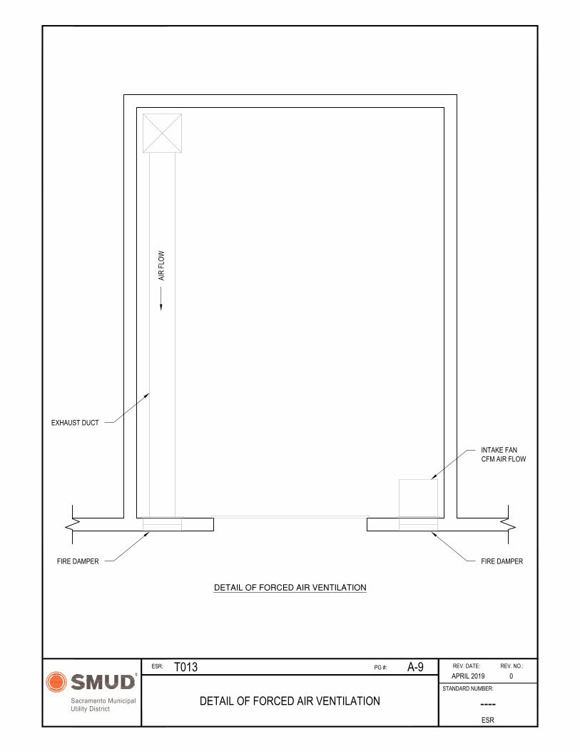
2.4.5. Forced Ventilation: Forced ventilation is based on the calculated transformer losses of the maximum installed infrastructure capability of the enclosure and is achieved by means of a fan sized to meet the CFM requirements
listed in Appendix A-10.
2.4.5.1. The fan shall vent from the outside air via direct-drive.
2.4.5.2. The fan shall be an Air Movement and Control Association (AMCA)
Type A or B spark resistant with an explosion-proof motor.
2.4.5.3. The fan shall be covered by a 0.5-inch mesh screen on both sides.
2.4.5.4. The fan shall be controlled via thermostat inside the enclosure. The fans shall be set to operate at 90°F and shut off at temperatures below 70°F.
2.4.5.5. A means to manually control the fans shall be provided inside the enclosure.
2.4.5.6. All vent openings for forced ventilation shall have a minimum
opening space of 576 in2. Please reference 2.8.3 for additional vent-placement restrictions and requirements.
2.4.5.7. All ventilation openings shall be covered with a durable and secure screen, grating or louver.
2.4.5.8. All ventilation openings to the indoors shall be provided with
automatic closing fire dampers that operate in response to an enclosure fire. Such dampers shall possess a standard fire rating of not less than 1.5 hours.

ENG. SPEC.
T013
REV.
2
ELECTRIC SERVICE REQUIREMENTS FOR CUSTOMER OWNED AND CONSTRUCTED TRANSFORMER
ENCLOSURE
Page 7
of 13
2.5. Access
There shall be a minimum clear working space of 20 feet, rated for 26,000-pound vehicle, with all-weather access to the enclosure. This area shall be at the same elevation as the floor of the enclosure. SMUD must have every day 24-hour access to the enclosure.
2.6. Duct
All primary and secondary ducts shall be constructed by the Customer. The number and size of ducts for the primary cable will be determined by the SMUD Engineering Designer. The physical size, number, and location of
service cable ducts shall be determined by the Customer. Details of duct systems shall be submitted by the Customer for SMUD approval.
2.7. Fire Suppression and Detection
2.7.1. SMUD requires no fire suppression or detection system in an enclosure
provided the criteria of section 2.2.1 are met. If a fire suppression system is installed due to requirements by the local authority having jurisdiction, desire of the owner, or because the requirements of section 2.2.1 are not met, the suppression system shall be a pre-action fire sprinkler designed in
accordance with section 2.7.1.1. A wet fire sprinkler system is allowed in lieu of a pre-action fire sprinkler system only if all criteria of section 2.7.1.2 are met. SMUD shall approve the design of any fire suppression system prior to delivery of the transformer.
2.7.1.1. Pre-action fire sprinklers
2.7.1.1.1. Pre-action fire sprinklers shall be double interlock.
2.7.1.1.2. All associated detection shall be heat type detectors.
2.7.1.1.3. The sprinkler heads are to be intermediate temperature rated and standard response.
2.7.1.1.4. The sprinkler heads are to have a minimum k-factor of 8.0
2.7.1.1.5. The design density for the enclosure is to be a minimum of 0.30
gpm/sf.
2.7.1.1.6. Sprinkler heads are to be protected with listed guards.
2.7.1.1.7. Penetrations shall be sealed with an approved fire stopping system.
2.7.1.2. Wet fire sprinklers
2.7.1.2.1. Sprinkler piping is not to run directly above the transformer and associated wiring and is to be located as far to the rear or the side of the enclosure as possible.
2.7.1.2.2. The sprinkler heads are to be intermediate temperature rated
and standard response.
2.7.1.2.3. The sprinkler heads shall have a minimum k-factor of 8.0

ENG. SPEC.
T013
REV.
2
ELECTRIC SERVICE REQUIREMENTS FOR CUSTOMER OWNED AND CONSTRUCTED TRANSFORMER
ENCLOSURE
Page 8
of 13
2.7.1.2.4. The design density for the enclosure is to be a minimum of 0.30 gpm/sf.
2.7.1.2.5. Sprinkler heads are to be protected with listed guards.
2.7.1.2.6. A single control valve that controls the water supply to all sprinkler heads protecting enclosure shall be provided and
located in the enclosure, to the rear, and easily visible and accessible to personnel without the use of a ladder or other tool.
2.7.1.2.7. A tamper switch connected to the building’s fire alarm or sprinkler monitoring system shall be provided on the control valve.
2.7.1.2.8. Penetrations shall be sealed with an approved fire stopping
system.
2.8. Adjacent Walls
2.8.1. If the enclosure is not equipped with fire sprinklers, the outside walls for a minimum of ten (10) feet to the sides and above the opening shall have an
exterior fire-resistance rating of three (3) hours (Section 2.2.1).
2.8.2. For enclosures protected by a fire sprinkler system, a one (1) hour fire rating
is allowed for the outside walls and any openings, including protective and closing devices, as per the CEC (see Section 2.2.2 or 2.2.3).
2.8.3. When a vented door or gate is used as the opening of the enclosure, no penetrations, openings, vents, or operable windows shall be placed on the outside wall 10 feet above the enclosure and within 20 feet on either side (Section 2.2.3). This will reduce the chances of contamination to the building
in the event of a fire.
2.9. Solid Door/Gate
2.9.1. A solid door(s) and/or gate(s) shall be provided for each enclosure opening to facilitate transformer/cubicle operation and maintenance. Submittals are
required for the door and/or gate design.
2.9.2. The solid door(s) and/or gate(s) shall completely block enclosure opening(s)
to prevent unauthorized entry. The door and/or gate design shall have provisions for a SMUD padlock to securely lock the closed door(s) and/or gate(s). The door(s) and/or gate(s) shall have provisions to lock in the fully open position. Door(s) and/or gate(s) open position shall clear the 20' area in
front of the enclosure opening(s). Door(s) and/or gate(s) locked in open position shall not block building access openings.
2.9.3. It is preferred that the door(s) and/or gate(s) shall be easily removable to allow installation and removal of equipment.
2.10. Grounding
2.10.1.Submittals are required for the grounding system.

ENG. SPEC.
T013
REV.
2
ELECTRIC SERVICE REQUIREMENTS FOR CUSTOMER OWNED AND CONSTRUCTED TRANSFORMER
ENCLOSURE
Page 9
of 13
2.10.2.The Customer shall provide ground points in the enclosure as specified by SMUD Electric Service Requirement T007 for specific equipment being installed.
2.10.3.Ground rods shall only be driven in the presence of the SMUD Inspector.
2.10.4.Each ground rod shall be tested by SMUD and must measure 25 ohms or less. Additional grounding requirements may be necessary if any ground rod does not meet the 25 ohm requirement.
2.10.5.The grounding system shall be bonded to the building foundation rebar in at least two separate locations. The connector and joint compound shall be
suitable for bimetallic connections.
2.11. Foreign Objects
Pipes, ducts, vents, or other foreign objects not required for the service shall not enter or pass through the enclosure.
3. MATERIAL
3.1. Material Furnished and Installed by Customer
3.1.1. General
Certain materials to be incorporated in the work may be designated under a trade name or the name of the manufacturer, for convenience in designation
on the plans or in the specifications. Where materials are specified by a particular designation, or equal, the Customer may use an alternative material which is of equal quality and of the required characteristics for the purpose intended, subject to SMUD approval.
The Customer shall request approval of a proposed substitution in writing accompanied by complete data as to the quality of the material proposed.
Such request shall be made in ample time to permit due consideration for approval without delaying the work. At least ten (10) working days are required to review a material submittal. The burden of proof as to the equality or suitability of alternatives shall be upon the Customer. Samples
may be required to determine equality. SMUD shall be the sole judge as to the equality and suitability of alternative materials. Materials incorporated in the work prior to approval of their use by SMUD shall be at the Customer's risk and subject to subsequent rejection.
3.1.2. Conduit
All four (4) inch, five (5) inch and six (6) inch conduit shall be polyvinylchloride (PVC) DB 120, gray color in accordance with the latest revision of ASTM F512. Conduit shall be any manufacturer meeting
specification.

ENG. SPEC.
T013
REV.
2
ELECTRIC SERVICE REQUIREMENTS FOR CUSTOMER OWNED AND CONSTRUCTED TRANSFORMER
ENCLOSURE
Page 10
of 13
3.1.3. Elbow
All four (4) inch, five (5) inch and six (6) inch elbows shall be polyvinylchloride (PVC), Schedule 40. Four (4) inch elbows shall have a 30- inch radius, five (5) inch elbows shall have a 36-inch radius, and six (6) inch elbows shall have a 48-inch radius and may need to be concrete encased.
Please refer to individual Job drawings.
3.1.4. End Bell
End bells shall be solid one-piece type, polyvinylchloride (PVC), Schedule 40, gray color. End bells shall conform to NEMA Publication No. TC3, Type
III application. End bells shall be the following, or SMUD approved equal:
4" 5" 6"
Prime Conduit EB400 EB500 EB600 Cantex 5144012 5144013 5144014 JM Eagle 61500400 61500500 61500600
3.1.5. Conduit Plug
Conduit plugs shall be plastic tapered for appropriate conduit size. Plugs
shall be the following or SMUD approved equal:
4" 5" 6"
Prime Conduit PEPT400 PEPT500 PEPT600 Cantex 5315262 5315263 5315264 JM Eagle 61800400 61800500 61800600
3.1.6. Other material may be specified by the SMUD Engineering Designer in the SMUD provided commitment and covered by Electrical Service Requirements, Distribution Underground Structure Engineering Specification T007.
3.2. Material Furnished by SMUD and Installed by Customer
SMUD will provide 5/8" x 8' copper clad steel ground rods for installation by the Customer as directed by SMUD.
3.3. Material Furnished and Installed by SMUD
SMUD will provide and install the above grade: secondary junction box enclosure and terminations, transformer(s) and switching cubicle(s) - as required.

ENG. SPEC.
T013
REV.
2
ELECTRIC SERVICE REQUIREMENTS FOR CUSTOMER OWNED AND CONSTRUCTED TRANSFORMER
ENCLOSURE
Page 11
of 13
4. SUBMITTALS
4.1. The Customer shall submit documentation showing compliance with this specification. This documentation shall be submitted prior to application for permit with the Authority Having Jurisdiction (AHJ). The purpose of this
requirement is to allow the Customer to provide the AHJ with SMUD approved documentation.
4.2. The Customer shall submit to SMUD three (3) complete sets of plans and specifications for approval. The submittal shall include the following information:
4.2.1. One Line Diagram showing number of conduits, number of service conductors (type & size) from the utility transformer, utility junction box, main switchboard and main panels.
4.2.2. Site plan showing location of enclosure and adjacent streets.
4.2.3. Construction drawings including as a minimum: door(s) and/or gate(s), exterior elevations, enclosure floor, enclosure layout with SMUD installed equipment and documentation showing compliance with this specification.
4.3. One complete set of documentation will be returned with SMUD comments. A minimum of ten (10) working days shall be required for submittal review.
4.4. Submittals marked "NOT APPROVED" shall be corrected and resubmitted.
4.5. Approval by SMUD is limited only to areas occupied by SMUD equipment. Approval is only for the purposes of assuring the operability of SMUD equipment. SMUD assumes no responsibility for the correct application or
safety of owner installed equipment or design.
4.6. Submittals shall be sent to:
SMUD New Services Grid Assets, MS EA105
P.O. Box 15830 Sacramento, CA 95852-0830
5. APPROVAL BY OTHER AGENCIES
The Customer shall submit letters from the AHJ Building Department and other
applicable agencies detailing their inspection of the enclosure and stating their acceptance and approval. Written approval of acceptance by all applicable agencies must be received by SMUD before SMUD will place equipment.

ENG. SPEC.
T013
REV.
2
ELECTRIC SERVICE REQUIREMENTS FOR CUSTOMER OWNED AND CONSTRUCTED TRANSFORMER
ENCLOSURE
Page 12
of 13
6. INSPECTION
6.1. SMUD will provide an Inspector who will be the line of communication between the Customer and SMUD during construction. The hours of work for the Inspector are from 8:00 A.M. to 3:00 P.M., Monday through Friday. All
work requiring the presence of the Inspector shall be scheduled during these hours. An advance notice of two (2) full working days shall be given to the Inspector for all work to be inspected.
6.2. The Customer shall notify SMUD’s Inspection Scheduling Group at telephone number (916) 732-5905 to arrange for inspection.
6.3. All material and work shall be subject to inspection, examination, and testing by SMUD, at any time during manufacture, installation, or construction. The Customer shall provide and maintain proper facilities and safe access for
such inspections or testing. The costs of all tests required under this inspection will be paid by the Customer.
6.4. SMUD shall have the right to reject defective material and work. Rejected work shall be corrected and rejected material shall be replaced with proper material. The Customer shall promptly segregate and remove rejected material from the job site.
6.5. Failure of the Customer to adhere to the above provisions may result in the Customer being required, at his/her expense, to remove, uncover, or
otherwise enable inspection of such work by the Inspector.
6.6. Rejected work may result in delaying electric service until these
inadequacies are corrected. The costs of correcting rejected work shall be paid by the Customer.
7. INSTALLATION
7.1. Sealing Ducts
All secondary ducts shall be sealed by the customer, after the ducts have been inspected and cable installed. Sealing shall be for the purposes of
stopping water, smoke, and fire.
7.2. Testing
7.2.1. Ducts constructed for SMUD installed cable shall be thoroughly cleaned and tested. The test shall involve drawing a mandrel through each duct. The
SMUD Inspector will furnish mandrels. The mandrel test shall be pulled only in the presence of the Inspector.
7.2.2. Ducts which do not pass the mandrel test shall be repaired and retested. A brush shall not be used in any plastic duct.
7.2.3. A flat tape polyester pull line with a minimum strength of 2500 lbs. shall be left in each duct as a "sleeper".

ENG. SPEC.
T013
REV.
2
ELECTRIC SERVICE REQUIREMENTS FOR CUSTOMER OWNED AND CONSTRUCTED TRANSFORMER
ENCLOSURE
Page 13
of 13
Appendix A: Construction Standards Drawings
The customer and/or their representatives or contractors shall adhere to the Construction Standard Drawings listed in the table below, unless otherwise specified in writing by a SMUD inspector or designer. The Customer shall review all drawings. Any questions or comments shall be brought to
Sacramento Municipal Utility District's (SMUD) attention for clarification or resolution.
Construction Standards Drawings
Drawing Title Page
Number
ONE TRANSFORMER A-1
TWO TRANSFORMERS A-2
TWO TRANSFORMERS & ONE J-BOX A-3
ONE TRANSFORMER & ONE AIR INSULATED SWITCH A-4
ONE TRANSFORMER & ONE SF6 SWITCH A-5
TWO TRANSFORMERS, ONE J-BOX, & ONE AIR INSULATED SWITCH A-6
TWO TRANSFORMERS, ONE J-BOX, & ONE SF6 SWITCH A-7
NATURAL OR FORCED AIR VENTILATION VENT DETAIL A-8
DETAIL OF FORCED AIR VENTILATION A-9
VENTILATION GUIDELINES A-10

NO BUILDING WINDOWS, VENTS,PROTRUSIONS, OR INTAKES IN CLEARANCEAREA IF VENTILATED GATE OR DOORCOVERS ENCLOSURE ENTRANCE.
CLEARANCE AREA
SEE ELECTRIC SERVICEREQUIREMENTS, DISTRIBUTIONUNDERGROUND STRUCTURE,ENGINEERING SPECIFICATIONT007. DRAWING UVD2.2 OR UVD2.3A FORTRANSFORMER PAD SIZE PER SMUDDESIGNER.
BUILDING WALL
CEILINGHEIGHT
REV. NO.:REV. DATE:
ONE TRANSFORMERESR
STANDARD NUMBER:
R
Sacramento Municipal
Utility District
3MARCH 2020
----
ESR: PG #:T013 A-1
3'-6"MIN.
3'-6"MIN.
3'-6"MIN.
4'MIN. 8' MIN.
OPERATINGCLEARANCE
20' MIN. CLEARWORK AREA
TRAFFIC RATED
20' 20'
15'MIN.
10'MIN.

ELEVATION(GATE NOT SHOWN)
PLAN
BUILDING WALL
REV. NO.:REV. DATE:
TWO TRANSFORMERSESR
STANDARD NUMBER:
R
Sacramento Municipal
Utility District
0MARCH 2020
----
ESR: PG #:T013 A-2
NO BUILDING WINDOWS, VENTS,PROTRUSIONS, OR INTAKES IN CLEARANCEAREA IF VENTILATED GATE OR DOORCOVERS ENCLOSURE ENTRANCE.
20' MIN. CLEAR
WORK AREA
TRAFFIC RATED
3'-6"
MIN.
4'
MIN.
3'-6"
MIN.
4'
MIN.
4'
MIN.8' MIN.
OPERATING
CLEARANCE
3'-6"
MIN.
3'-6"
MIN.
SEE ELECTRIC SERVICEREQUIREMENTS, DISTRIBUTIONUNDERGROUND STRUCTURE,ENGINEERING SPECIFICATION T007.DRAWING UVC1.7 AND U1S3D1 FORSECONDARY J-BOX AND DRAWINGUVD2.2 OR UVD2.3A FORTRANSFORMER PAD SIZE, PER SMUDDESIGNER.
20' 20'
15'
MIN.
10'
MIN.
CEILING HEIGHT
CLEARANCE AREA
8' MIN.
OPERATING
CLEARANCE

SMUDELECTRIC
SMUDELECTRIC
CLEARANCE AREA
ELEVATION(GATE NOT SHOWN)
PLAN
SEE ELECTRIC SERVICEREQUIREMENTS, DISTRIBUTIONUNDERGROUND STRUCTURE,ENGINEERING SPECIFICATION T007.DRAWING UVC1.7 AND U1S3D1 FORSECONDARY J-BOX AND DRAWINGUVD2.2 OR UVD2.3A FORTRANSFORMER PAD SIZE, PER SMUDDESIGNER.
SECONDARY JUNCTION BOX (48" x 48")
BUILDING WALL
CEILINGHEIGHT
NON -CONCRETESECONDARY J-BOX48" X 96" X 48"
REV. NO.:REV. DATE:
TWO TRANSFORMERS & ONE J-BOXESR
STANDARD NUMBER:
R
Sacramento Municipal
Utility District
3MARCH 2020
----
ESR: PG #:T013 A-3
NO BUILDING WINDOWS, VENTS,PROTRUSIONS, OR INTAKES IN CLEARANCEAREA IF VENTILATED GATE OR DOORCOVERS ENCLOSURE ENTRANCE.
15'
MIN.
10'
MIN.
20' 20'
20' MIN. CLEAR
WORK AREA
TRAFFIC RATED
3'-6"
MIN.
3'-6"
MIN.
3'-6"
MIN.
3'-6"
MIN.
4'
MIN.
4'
MIN.
3'-6"
MIN.
4'
MIN.
4'
MIN.
8' MIN.
OPERATING
CLEARANCE
8' MIN.
OPERATING
CLEARANCE

SMUDELECTRIC
REV. NO.:REV. DATE:
ONE TRANSFORMER & ONE AIR INSULATED SWITCHESR
STANDARD NUMBER:
R
Sacramento Municipal
Utility District
3MARCH 2020
----
ESR: PG #:T013 A-4
ELEVATION(GATE NOT SHOWN)
PLAN
RPM HANDHOLE BOXFOR SWITCHGEAR
CLEARANCE AREA
SEE ELECTRIC SERVICEREQUIREMENTS, DISTRIBUTIONUNDERGROUND STRUCTURE,ENGINEERING SPECIFICATIONT007. DRAWING UVD2.2 ORUVD2.3A FOR TRANSFORMERPAD SIZE, PER SMUD DESIGNER.
BUILDING WALL
SEE ELECTRIC SERVICEREQUIREMENTS, DISTRIBUTION
UNDERGROUND STRUCTURE,ENGINEERING SPECIFICATION T007.
DRAWING UGA2.5 AND UVC1.4 ORUVC1.5. ORIENTATION OF BOX PER
SMUD DESIGNER.
ACCESS HATCH
NO BUILDING WINDOWS, VENTS,PROTRUSIONS, OR INTAKES IN CLEARANCEAREA IF VENTILATED GATE OR DOORCOVERS ENCLOSURE ENTRANCE.
20' MIN. CLEAR
WORK AREA
TRAFFIC RATED
4'
MIN.
8' MIN.
OPERATING
CLEARANCE
3'-6"
MIN.
8'
MIN.
3'-6"
MIN.
4'
MIN.
3'-6"
MIN.
CEILING HEIGHT
20' 20'
15'
MIN.
10'
MIN.

SMUDELECTRIC
REV. NO.:REV. DATE:
ONE TRANSFORMER & ONE SF6 SWITCHESR
STANDARD NUMBER:
R
Sacramento Municipal
Utility District
0MARCH 2020
----
ESR: PG #:T013 A-5
ELEVATION(GATE NOT SHOWN)
PLAN
RPM HANDHOLE BOXFOR SWITCHGEAR
CLEARANCE AREA
SEE ELECTRIC SERVICEREQUIREMENTS, DISTRIBUTIONUNDERGROUND STRUCTURE,ENGINEERING SPECIFICATIONT007. DRAWING UVD2.2 ORUVD2.3A FOR TRANSFORMERPAD SIZE, PER SMUD DESIGNER.
BUILDING WALL
SEE ELECTRIC SERVICEREQUIREMENTS, DISTRIBUTION
UNDERGROUND STRUCTURE,ENGINEERING SPECIFICATION T007.
DRAWING UGA2.5 AND UVC1.4 ORUVC1.5. ORIENTATION OF BOX PER
SMUD DESIGNER.
NO BUILDING WINDOWS, VENTS,PROTRUSIONS, OR INTAKES IN CLEARANCEAREA IF VENTILATED GATE OR DOORCOVERS ENCLOSURE ENTRANCE.
20' MIN. CLEARWORK AREA
TRAFFIC RATED
3'-6"MIN.
3'-6"MIN.
3'-6"MIN.
3'-6"MIN.
4'MIN.
4'MIN.8' MIN.
OPERATINGCLEARANCE
15'MIN.
10'MIN.
20' 20'
CEILING HEIGHT

SMUDELECTRIC
SMUDELECTRIC
ELEVATION(GATE NOT SHOWN)
PLAN
REV. NO.:REV. DATE:
TWO TRANSFORMERS, ONE J-BOX & ONE AIR INSULATEDSWITCH
ESR
STANDARD NUMBER:
R
Sacramento Municipal
Utility District
0MARCH 2020
----
ESR: PG #:T013 A-6
SEE ELECTRIC SERVICEREQUIREMENTS, DISTRIBUTION
UNDERGROUND STRUCTURE,ENGINEERING SPECIFICATION T007.
DRAWING UGA2.5 AND UVC1.4 ORUVC1.5. ORIENTATION OF BOX PER
SMUD DESIGNER.
20'-0"
15'-0"
MIN.
10'-0"
MIN.
3'-6"
MIN.
4'-0" MIN.
8'-0"
MIN.
4'-0"
MIN.
8'-0" MIN.
OPERATING CLEARANCE
SEE ELECTRIC SERVICEREQUIREMENTS, DISTRIBUTIONUNDERGROUND STRUCTURE,ENGINEERING SPECIFICATION T007.DRAWING UVC1.7 AND U1S3D1 FORSECONDARY J-BOX AND DRAWINGUVD2.2 OR UVD2.3A FORTRANSFORMER PAD SIZE, PERSMUD DESIGNER.
SECONDARY JUNCTION BOX (48" x 48")
3'-6"
MIN.
3'-6"
MIN.
20'-0" MIN.
CLEAR
WORK AREA
TRAFFIC
RATED
20'-0"
BUILDINGWALL
NON -CONCRETESECONDARY J-BOX48" X 96" X 48"
CLEARANCE AREA
CEILING HEIGHT
NO BUILDING WINDOWS, VENTS, PROTRUSIONS,OR INTAKES IN CLEARANCE AREA IF VENTILATEDGATE OR DOOR COVERS ENCLOSURE ENTRANCE.
4'-0"
MIN.
3'-6"
MIN.
3'-6"
MIN.
8'-0"
MIN.

SMUDELECTRIC
SMUDELECTRIC
REV. NO.:REV. DATE:
TWO TRANSFORMERS, ONE J-BOX & ONE SF6 SWITCHESR
STANDARD NUMBER:
R
Sacramento Municipal
Utility District
0MARCH 2020
----
ESR: PG #:T013 A-7
ELEVATION(GATE NOT SHOWN)
PLAN
SEE ELECTRIC SERVICEREQUIREMENTS, DISTRIBUTION
UNDERGROUND STRUCTURE,ENGINEERING SPECIFICATION T007.
DRAWING UGA2.5 AND UVC1.4 ORUVC1.5. ORIENTATION OF BOX PER
SMUD DESIGNER.
20'-0"
15'-0"MIN.
10'-0"MIN.
3'-6"MIN.
8'-0" MIN.OPERATINGCLEARANCE
SEE ELECTRIC SERVICEREQUIREMENTS, DISTRIBUTIONUNDERGROUND STRUCTURE,ENGINEERING SPECIFICATION T007.DRAWING UVC1.7 AND U1S3D1 FORSECONDARY J-BOX AND DRAWINGUVD2.2 OR UVD2.3A FORTRANSFORMER PAD SIZE, PERSMUD DESIGNER.
SECONDARY JUNCTION BOX (48" x 48")
3'-6"MIN.
3'-6"MIN.
20'-0" MIN.CLEAR WORKAREA TRAFFIC
RATED
20'-0"
BUILDINGWALL
RPM HANDHOLEBOX FOR SWGR
CLEARANCE AREA
CEILING HEIGHT
3'-6"MIN.
4'-0"MIN.
4'-0" MIN.
NO BUILDING WINDOWS, VENTS, PROTRUSIONS,OR INTAKES IN CLEARANCE AREA IF VENTILATEDGATE OR DOOR COVERS ENCLOSURE ENTRANCE.
4'-0"MIN.
4'-0"MIN.
4'-0"MIN.
3'-6"MIN.

REV. NO.:REV. DATE:
NATURAL OR FORCED AIR VENTILATIONVENT DETAIL
ESR
STANDARD NUMBER:
R
Sacramento Municipal
Utility District
0AUG 2019
----
ESR: PG #:T013 A-8
SOLID DOOR
NOTE 1 - SIZE AND NUMBER OF VENTS ARE DEPENDANT ON VENTILATION REQUIREMENTS.NOTE 2 - INTAKE VENTS SHALL BE 1 FT. FROM ENCLOSURE FLOOR. OUTAKE VENTS SHALL
BE 1 FT. FROM ENCLOSURE CEILING.
SEE NOTE 1
1'-0"
1'-0"
VENTED DOOR (INTAKE VENT)
EXHAUST VENT
1'-0"
EXHAUST VENT (AS REQUIRED)
INTAKE VENT
REV. NO.:REV. DATE:
DETAIL OF FORCED AIR VENTILATIONESR
STANDARD NUMBER:
R
Sacramento Municipal
Utility District
0APRIL 2019
----
ESR: PG #:T013 A-9
DETAIL OF FORCED AIR VENTILATION
AIR
FLOW
FIRE DAMPER
EXHAUST DUCT
FIRE DAMPER
INTAKE FANCFM AIR FLOW

REV. NO.:REV. DATE:
VENTILATION GUIDELINESESR
STANDARD NUMBER:
R
Sacramento Municipal
Utility District
0AUG 2019
----
ESR: PG #:T013 A-10
kVA Min. Required Natural Ventilation(Vents x Size)
45 2 x 1ft.²
75 2 x 1ft.²
150 2 x 2ft.²
300 2 x 3.5ft.²
500 2 x 5.5ft.²
750 2 x 8ft.²
1000 2 x 11ft.²
1500 2 x 16ft.²
2000 2 x 21ft.²
2500 2 x 26.5ft.²
3325 2 x 35ft.²
kVA LOSSES (kW) Min CFM RequiredForced Ventilation
<75 1 124
150 2 247
300 3 371
300 4 494
500 5 618
750 6 742
750 7 865
1000 8 989
1000 9 1112
10 1236
1500 11 1360
1500 12 1483
13 1607
14 1730
2000 15 1845
16 1978
17 2101
2500 18 2225
19 2348
20 2472
21 2596
22 2719
23 2843
24 2966
25 3090
3325 26 3214
NOTE 1:VENTILATION AREA DOES NOT ACCOUNT FOR ANY SPACEOCCUPIED BY SCREENS, GRATES OR LOUVERS, WHICHNEED TO BE DEDUCTED FROM THE TOTAL AREA.
NOTE 2:THE MINIMUM REQUIRED VENTILATION AND MINIMUM CFMREQUIREMENTS ARE BASED ON THE MAXIMUM INSTALLEDINFRASTRUCTURE CAPABILITY OF THE ENCLOSURE.