customer handbook - deltadrive · 4.2.3 network connection rs485 ... trouble-shooting ... customer...
TRANSCRIPT

Customer handbook AC-Servocontroller DAC
Page 1
deltadrive
Customer handbook 05-2002
CUSTOMER HANDBOOK
Maintenance and service

Customer handbook AC-Servocontroller DAC deltadrive
Contents
1. Security specifications.............................................................................................................4
2. General information..................................................................................................................5
2.1 The deltadrive Group .........................................................................................................5 2.2 Short description of the deltadrive ...................................................................................5 2.3 Declaration of EU conformity ............................................................................................6
3. Device description ....................................................................................................................8
3.1 Technical data.....................................................................................................................8 3.1.1 Acceptable environment, ventilation, housing................................................................9 3.1.2 Conductor cross section ................................................................................................9 3.1.3 Fusing ............................................................................................................................9 3.1.4 LED displays ................................................................................................................10
3.2 Dimensions .......................................................................................................................11 3.3 Front view showing service features and connections ................................................12
4. Assembly and wiring.................................................................................................................13
4.1 General guidelines ...............................................................................................................13 4.2 Connector pin assignment ..............................................................................................14
4.2.1 Motor connection (plug X1)..........................................................................................14 4.2.2 Mains an DC bus connection (plug X2) .......................................................................14 4.2.3 Network connection RS485 (plug X3 and X4) .............................................................14 4.2.4 Signal connection (plug X5) .........................................................................................15 4.2.5 Encoder connection (plug X6)......................................................................................15 4.2.6 Signal connection (plug X7) .........................................................................................16 4.2.7 Options connection FB100 (plug X11) .........................................................................17 4.2.8 RS-232 interface PC connection (plug X10) ................................................................18 4.2.9 Options connection FBK100 (plug X11).......................................................................18 4.2.10 RS - 422 interface FBK100 (plug X10) ........................................................................19 4.2.11 Shielding connection....................................................................................................19 4.2.12 Ground connection.......................................................................................................19 4.2.13 Interface module (plug X7 / plug X11) .........................................................................20
4.3 Arrangement of jumpers..................................................................................................22 4.3.1 Rearranging the jumpers .............................................................................................23
4.5 Automatic station address detection...................................................................................24
5. Software installation...............................................................................................................25
5.1 Software installation with the FBK100 card...................................................................25
6. Servicing..................................................................................................................................26
7. Trouble-shooting ....................................................................................................................26
7.1 Servomotor problems ......................................................................................................26 7.1.1 Encoder-fails setup check............................................................................................26
Page 2 Customer handbook 05-2002 7.1.2 Blocked motor ..............................................................................................................26

Customer handbook AC-Servocontroller DAC deltadrive
7.2 Problems with the deltadrive-controller......................................................................... 26 7.2.1 Communications check................................................................................................ 26 7.2.2 Controller doesn't start................................................................................................ 27 7.2.3 LEDs blinking on controller ......................................................................................... 27 7.2.4 Motor starts turning immediately................................................................................. 27 7.2.5 Motor vibrates ............................................................................................................. 27 7.2.6 Motor "whistles" .......................................................................................................... 27 7.2.7 Analog inputs and outputs not functioning.................................................................. 27
8. Connector assignments for customer's application ........................................................... 28
8.2. Additional inputs and Outputs (plug X11) ..................................................................... 29
9. Three phase synchronous motors........................................................................................ 30
9.1 Frame type references..................................................................................................... 30 9.2 Options.............................................................................................................................. 30 9.3 Datasheet SAC 118M20.................................................................................................... 31 9.4 Datasheet SAC 90L20 ...................................................................................................... 32
Page 3 Customer handbook 05-2002

Customer handbook AC-Servocontroller DAC deltadrive
1. Security specifications deltadrive is constructed in accordance with the latest security specifications and with a high degree of protection against accidental contact. Appropriate use of the deltadrive: • deltadrive is to be used as a control device for synchronous and asynchronous machines.
The following security specifications and manipulation limitations are for the personal safety of individuals and of equipment and are to be strictly observed.
• The user is therefore responsible for proper installation and connections of motor, deltadrive and additional equipment in accordance with the recognized technical regulations and guidelines applicable in the country and region of its destination and use.
• Thus it is important to be aware of (and employ) correct cable dimensions, shielding, grounding, switch-offs, separation and over-current protection.
• All local specifications and regulations must be observed without fail. • Any operation on the device can only be undertaken by experts trained for this purpose. • Any operation on the device can only be performed using appropriate tools. • Any operation on the deltadrive is to be undertaken only in a voltageless condition, i.e.,
neither the power source nor any potential auxiliary supply nor the rating voltage of another connected device can be switched on. Take care to have a secure isolation braker. For additional security employ the appropriate warning signs, physical barriers, etc.
• As a result of the device-internal electrical charge, high voltage can exist for a lengthy period even after the main's voltage has been switched off. Before electrical contact is made, take care to insure that the voltage between the power clamps A+ and D- is less than 40V. Failure to follow this advice can lead to serious injury or even death.
• No additional cards, ICs, plugs, etc. can be inserted or removed under voltage. • Changes may not be made to the deltadrive without the permission of the manufacturer.
If these security specifications and operation limits are not strictly observed, the risk of danger exists via:
• Accident - from uncontrolled movement of parts, motors or machines.
• Destruction of the device or parts thereof. • Destruction of additional components such as motor, machine, etc. • Electrical shock to the human body.
Page 4 Customer handbook 05-2002

Customer handbook AC-Servocontroller DAC
deltadrive
2. General information
2.1 The deltadrive Group Various companies have joined together under the name “The deltadrive Group” for the purpose of developing, producing and marketing state-of-the-art digital AC drives.
2.2 Short description of the deltadrive The deltadrive 3-phase converter offers a modular drive concept for servo motors with sine-wave conduction and encoder feedback. deltadrive can be utilized as a control device for synchronous machines with sine-wave commutation and for asynchronous machines with field-oriented vector control. The customer’s application determines the choice of motor. The fully digitized 3-phase control device enables direct connection to the 230VAC mains. We recommend the use of interference suppression filters. The basic model of the deltadrive is equipped with encoder feedback. This allows the use of synchronous and asynchronous motors. A digital input allows you to switch from automatic speed control to position control and vice versa. This allows, e.g. the use of the drive as the main drive with spindle positioning. Up to 32 devices can be networked together (without repeater) over the RS485 interface. (With repeater = 62 devices) The device is equipped with 8 digital inputs and 8 digital outputs as well as 3 analog inputs and 2 analog outputs. Numerous applications can be implemented by insertion of the FB 100 optional card (functional board) equipped with an additional 4 digital inputs and 8 digital power outputs (2A), encoder analysis and the RS 232 interface. Inputs and outputs can be programmed with the help of application software. Configuration, start-up and diagnoses take place with the help of a PC user interface via the standard RS-232 interface. Operating condition and errors are displayed on LED’s located on the front of the device. Analog signals such as programmed speed, power and actual speed are digitized and processed by the microprocessor. An adaptive control algorithm ensures on line that the deltadrive is constantly being adjusted for any temperature dependent parameters. A real-time multitasking operating system and the high resolution of speed signals enable a considerable degree of control exactitude and dynamic. This in turn enables good speed stability and torque linearity. This ensures reliable use in high-precision applications. Additional applications - such as spindle positioning, indexing, winder with tension control, electronic gearing and integration of entire customer applications in the drive - are in wide use. For multi-axis operations the FBK 100 options card can be mounted in a drive. This makes an on-line connection with the MMI (man-machine interface) unnecessary because the gateway on the FBK 100 maintains communication with the controller at a rate of 340 kbaud. An RS-422 interface communicates with the PC/MMI at a rate of 115 kbaud. Additional memory, master encoder interpretation and a virtual encoder creation are other features of this intelligent application card.
Page 5 Customer handbook 05-2002

Customer handbook AC-Servocontroller DAC deltadrive
2.3 Declaration of EU conformity
Declaration of EU conformity:
Declaration of conformity, specifically with the EU – EMC Guideline 89/336/ECC We, STA STATE OF THE ART ENGINEERING AG Dorfstrasse 38 CH- 6341 Baar Switzerland
Switzerland Declare under our sole responsibility that the product deltadrive series model is exclusively intended for incorporation in another machine, and in conformity with the provision of the following Council Directive: version 89/392/EEC and 93/68/EEC. The following standards were referred to in assessing the product: Standards for assessment of immunity to noise or disturbance: • EN 50082-2 5/95 EMC – Basic standard for interference immunity, industrial area Standards for assessment of radiated interference: • EN 50081-2 8/93 EMC – Basic standard for interference immunity, industrial area • EN 55011 93 Limiting values and test measurement procedures for radio interference from high
frequency industrial devices Copyright © STA STATE OF THE ART ENGINEERING AG 2001. All rights reserved. Reproduction, transfer, distribution or storage of part or all of the contents in this document in any form (printed, photocopied, microfilm or in any other process), or processed or reproduced by use of any electronic system, without the specific prior written permission of STA STATE OF THE ART ENGINEERING AG is strictly prohibited. STA STATE OF THE ART ENGINEERING AG, operating under the deltadrive Group other product and company names mentioned (R&D Deltadrive Phils Inc., Otto Bartholdi AG Motoren) herein might be trademarks or tradenames of their respective owners. STA STATE OF THE ART ENGINEERING AG operates a policy of continuous development. STA STATE OF THE ART ENGINEERING AG; reserves the right to make any changes and improvements to any of the products described in this document without prior notice. The contents of this document are provided “ as is”. Except as required by applicable law, no warranties of any kind, either express or implied, including, but not limited to, the implied warranties of merchantability or contents of this document. STA STATE OF THE ART ENGINEERING AG reserves the right to revise this document or withdraw it any time without prior notice. This declaration should not be implemented as guaranteeing characteristics. The security specifications of the manual are to be observed in all cases.
Declaration by the Company Management
Page 6 Customer handbook 05-2002

Customer handbook AC-Servocontroller DAC deltadrive
Messrs. Robert Ritter / Markus Schneider Baar, 05-29-2002 Signature: Signature: This declaration should not be construed as guaranteeing characteristics. The security specifications of the handbook are to be observed in all cases.
Page 7 Customer handbook 05-2002

Customer handbook AC-Servocontroller DAC deltadrive
3. Device description
3.1 Technical data (Valid for environmental temperatures up to 40 °C max.)
Nominal data DAC 03 DAC 05 DAC 08 DAC 016 DAC 030 Nominal AC voltageUN VAC 1x or 3x 80 - 230 +max. 10%, 50/60 Hz Nominal AC power WN kVA 1.0 1.8 2.8 5.5 10.0 System fuse (FF) all devices individually A 10 10 10 35 50 Maximum power (t=60s) kVA 1.8 3.3 4.6 9.0 15.0 Maximum power (t=5s) kVA 2.5 4.8 6.5 13.0 22.0 Rated output voltage V 3x 0 .. 200V, max. 0.87UN, 0 .. 800 Hz Short circuit & ground fault-protection yes
Nominal output current IN Aeff 3 5 8 16 30 Maximum current (t=60s) Aeff 4.3 7.1 11.3 22.5 42.0 Maximum current (t=5s) Aeff 6 10 16 32 55 Internal braking resistance Ω - 39 39 30 13
Braking power (t=5s) kW - 3.5 3.5 5 9.5 Continuous braking power kW - 0.5 0.5 1.0 1.5 Working voltage for engaging brake V 370 Intermediate circuit voltage VDC 110 - 360 Clock frequency of output stage kHz 8 Residual voltage drop at nominal power V 4 Quiescent dissipation power W 20 20 20 25 25 Dissipation power at nominal current (no brake resistance)
W 55 80 115 220 385
Inputs Analog-inputs, res 10bit (Option 14bit) V ± 10 Common mode voltage - max. V ± 25 Input resistance kΩ 70
Digital-inputs V 0 .. 24 (Switch threshold 10V) Common mode voltage - max. V ± 25 Auxiliary voltage supply VH (UN = 0V) V 24 Power consumption PH W 8 8 8 12 12 Outputs Analog-outputs, resolution 8bit V ± 10 Output current - max. mA 50 Digital outputs V 0 .. 24 Output current - max. mA <200 Digital power outputs (external supply) V <60 Output current - max. A 2
Page 8 Customer handbook 05-2002

Customer handbook AC-Servocontroller DAC
deltadrive
3.1.1 Acceptable environment, ventilation, housing Environmental temperature: 0 .. 40oC Storage temperature: -25 ... +85oC Humidity class: F DIN40040 Protection type: IP 20 DIN40050, IEC144 Installation position: vertical (see sec. 3.2) Ventilation: free convection
take care to provide sufficient (forced) air ventilation in a closed switch cabinet
3.1.2 Conductor cross section In accordance with EN 60204 Part1, or VDE 0113 we recommend the following conductor cross sections:
DAC 03 .. 08 DAC 016 DAC 030 mains connection (plug X2)
1.5 mm2 (e.g. ACO powerflex
CY 4x1.5mm2)
2.5 mm2 (e.g. ACO powerflex
CY 4x2.5mm2)
4.0 mm2 (e.g. cabloflex C 4x4.0mm2)
protective ground (sec. 4.5.10)
>10mm2 (leakage converter current
>3.5mA VDE 160 par.6.5.1.2) motor connection (plug X1)
same cable as mains connection
external braking resistance
1.5 mm2 (e.g. ACO colorflex LI sw)
2.5 mm2 (e.g. ACO colorflex LI sw)
encoder connection (plug X6)
paired, shielded (e.g. ACO colorflex CY-UL 4x2x0.14mm2 or 7x2x0.14mm2)
analog set value (plug X5, X7)
0.5 mm2 (e.g. ACO powerflex CY 3x0.5mm2)
control signal (plug X5, X7)
0.25mm2 (e.g. ACO colorflex 0.25mm2)
network connection RS 485 (plug X3, X4)
4 poled standard modular cable with EMC ferrite core
PC-connection RS 232 or RS 422 (plug X10)
null-modem link cable RS232 (FB100/101/102) or RS 422 - RS 232 adapter (FBK100)
3.1.3 Fusing Mains connection: as per table 3.1, page 8. The use of 30mA fl-circuit breakers is not possible due to the leakage current (up to100mA) of the converter. Motor connection: electronically fused, shortcircuit and ground-proof Braking resistance: electronically fused Control inputs: not fused Control outputs: not fused
Page 9 Customer handbook 05-2002
Customer handbook AC-Servocontroller DAC deltadrive
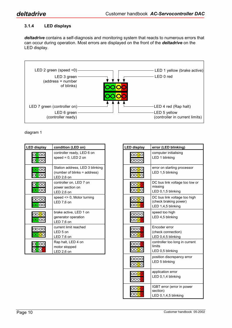
3.1.4 LED displays deltadrive contains a self-diagnosis and monitoring system that reacts to numerous errors that can occur during operation. Most errors are displayed on the front of the deltadrive on the LED display.
LED 3 green(address = number
of blinks)
LED 2 green (speed =0) LED 1 yellow (brake active)LED 0 red
LED 4 red (Rap halt)LED 5 yellow(controller in current limits)
LED 6 green(controller ready)
LED 7 green (controller on)
diagram 1
LED display condition (LED on)
controller ready, LED 6 on speed = 0, LED 2 on
Station address, LED 3 blinking (number of blinks = address) LED 2,6 on
controller on, LED 7 on power section on LED 2,6 on
speed <> 0, Motor turning LED 7,6 on
brake active, LED 1 on generator operation LED 7,6 on
current limit reached LED 5 on LED 7,6 on
Rap halt, LED 4 on motor stopped LED 2,6 on
LED display error (LED blinking)
computer initialising LED 1 blinking
error on starting processor LED 1,5 blinking
DC bus link voltage too low or missing LED 0,1,5 blinking
DC bus link voltage too high (check braking power) LED 1,4,5 blinking
speed too high LED 4,5 blinking
Encoder error (check connection) LED 0,4,5 blinking
controller too long in current limits LED 0,5 blinking
position discrepancy error LED 5 blinking
application error LED 0,1,4 blinking
IGBT error (error in power section) LED 0,1,4,5 blinking
Page 10 Customer handbook 05-2002

Customer handbook AC-Servocontroller DAC
deltadrive
3.2 Dimensions
G
deltadrive
δ
>=100mm
>=100mm
>=300mm
D
B
E
CF
E
H
A
L
K
K
DAC 03/05 DAC 08
DAC 030DAC 016
K
Dimensions in mm
A minimum space of 100 mm above andbelow must be observed for air ventilation.
deltadrive
δ
M3
M4
deltadrive
δ
M3
M4
diagram 2
Device type A B C D E F G H K L Weight DAC 03 60 205 208 260 25 222 30 5 65 15 2.7 kg DAC 05 60 205 208 260 25 222 30 5 65 15 2.9 kg DAC 08 60 205 208 250 25 222 30 5 95 15 4.6 kg
DAC 016 70 205 208 250 25 222 30 5 100 20 5.2 kg DAC 030 70 205 208 250 25 222 30 5 100 20 5.5 kg
Page 11 Customer handbook 05-2002

Customer handbook AC-Servocontroller DAC deltadrive
3.3 Front view showing service features and connections
Signal - LEDsready for operationDisplay of status anderror.
X11 FB100 D-SUB 44f• additional encoder• 4 digital inputs• 8 power outputs• Multiturn absolute encoder
X10 D-SUB 9m• RS 232-interface
(not activ at fast network)
X7 D-SUB 44f• 8 digital inputs• 8 digital outputs• 4 analog inputs• 2 analog outputs• auxillary (external) supply• 3 „high speed“ inputs
X6 D-SUB 15f• encoder connection
X5 plug 14 pol.for connection to thesignal cable
X3, X4 plug modularfor RS 485 interface
X2 plug 10 pol.for power connections
X1 plug 4 pol.for motor connection
DAC 08/FB100
diagram 3
X11 FBK100 D-SUB 44f• additional encoder• parallel port• daisy chain download
X10 RJ 45• RS 422-interface
DAC 08/FBK100
see diagram 3
see diagram 3
diagram 4
screw clampsfor power connectionsand motor connection
DAC 016/FB100
see diagram 3
see diagram 3
see diagram 3
see diagram 3
diagram 5
Page 12 Customer handbook 05-2002

Customer handbook AC-Servocontroller DAC
deltadrive
4. Assembly and wiring
4.1 General guidelines Inspection of new unit After unpacking the deltadrive or before assembly and operation, examine the unit for signs of possible damage in transit. Check the deltadrive’s name plate against the shipping documents and your original order. Wiring guidelines The following tips should help you avoid wiring problems. They are intended as guidelines. Shielding and interference suppression: Control signal cables should be shielded and normally should be grounded at both ends. Twisted-pair cables within the outer shielding should also be shielded individually if their length is more than 5 meters. Power cables should be shielded and the shielding grounded at both ends. Never use cables of too narrow a gauge because the skin effect puts uneven loads on small-diameter wires cable. To comply with EMC regulations (EU directive 89/392/EEC) we recommend ferrite cores on all cables. To avoid interference the cables should be laid in two groups (power, controls). These groups should be separated or laid in different channels. Keep the cables as short as possible (cable length > 20m ask the manufacturer). The two groups: • Power system (motor cable, mains cable, DC bus, etc.) • Control system (encoder, control signal, control supply, etc.) If devices incorporating power stage electronics are installed in or near switching/control units or attached to the same mains, precautions should be taken to avoid interference in the switches. • Inductive coils, switching devices and relay combinations should be operated with RC
circuits or diodes. • Sources of interference (power circuits, protective control circuits, etc.) are to be separated
and installed well away from the control circuits. • In general we recommend the use of an auto transformer to adjust the voltage from
3x400VAC to 3x230VAC for the deltadrive power supply. • We recommend noise suppression filters for critical applications.
Page 13 Customer handbook 05-2002

Customer handbook AC-Servocontroller DAC deltadrive
4.2 Connector pin assignment For cable selection please observe the recommendations for the conductor cross section in Sec. 3.1.2
4.2.1 Motor connection (plug X1)
W2V2U2PE
4321
Motor
prot. earth
4321
W2V2U2PE
DAC 03 - 08 DAC 016 - 030
4 poled plug connector -orange multipoint con-nector with cage tensiondrawspring type WAGO231-304/026-000
PHOENIX -printclamp typeFRONT 4..-6,35
diagram 6
4.2.2 Mains an DC bus connection (plug X2)
PEW1V1U1FD-D-A+A+
10987654321
mains
DC-bus
ext.brake resistance
prot. earth
98
76531A+
D-F
PEW1V1
U1
DAC 03 - 08 DAC 016 - 030
10 poled plugconnector - orangemultipoint connectorwith cage tensiondrawspring con-nection type WAGO231-310/026-000
PHOENIX -printclamp typeFRONT 4..-6,35
diagram 7
PE
4.2.3 Network connection RS485 (plug X3 and X4)
deltadrive 1 deltadrive 2 deltadrive n
X3
X4
diagram 8
Modular cabling with 4 poled modular plug system. Cables are available as accessories.
Page 14 Customer handbook 05-2002

Customer handbook AC-Servocontroller DAC
deltadrive
4.2.4 Signal connection (plug X5)
10987654321
+24VReadyOperateGNDRaphaltEnableDrive onGNDAD-AD+
Analog prgramm’dspeed value
11121314
P1SGND+-
Control inputs
Control outputs
Computerauxilliary power
Station number orPTC thermistor
Supply outputs
diagram 9
14 poled plug connector - Grey multipoint connector with cage tension drawspring connection type WAGO 231-114/0026-000
4.2.5 Encoder connection (plug X6)
15 poled female plug D-SUB on the deltadrive, pin contact (male) on the cable.
5 GND4 GND3 B+2 NP+1 A+
10 W+9 V-8 V+7 U-6 U+
15 W-14 +5V13 B-12 NP-11 A-
diagram 10
deltadrive Encoder D-Sub 15f with UVW/TAM
Signal Pin No. Color A+ 1 blue/black A- 11 blue B+ 3 green B- 13 green/black
NP+ 2 yellow NP- 12 yellow/black +5V 14 red GND 4 black
5 U+ 6 brown U- 7 brown/black V+ 8 grey V- 9 grey/black W+ 10 white W- 15 white/black
Page 15 Customer handbook 05-2002

Customer handbook AC-Servocontroller DAC deltadrive
4.2.6 Signal connection (plug X7)
44 poled female plug D-SUB on the deltadrive pin contact (male) on the cable.
Signal Sign. Pin No. Analog input 1
AD1+ AD1- GND
1 16 31
Analog input 2
AD2+ AD2- GND
2 17 32
Analog input 3
AD3+ AD3- GND
3 18 33
PTC resistor motor
PTC+ PTC-
Ground
4 19 34
Analog output 1
DA1 GND
14 29
Analog output 2
DA2 GND
15 30
Digital inputs E0 E1 E2 E3 E4 E5 E6 E7
6 7 8 9 10 11 12 13
Common reference
GND 39
High speed input 1
HS1+ HS1-
5 20
High speed input 2
HS2 GND
35 36
Digital outputs
O0 O1 O2 O3 O4 O5 O6 O7
21 22 23 24 25 26 27 28
ext. supply. 24V 37 Supply
(WARNING power total <
4W!)
+5V +15V -15V +24V GND
40 41 42 43 44
10 E49 E38 E27 E16 E05 HS1+4 PTC+3 AD3+2 AD2+1 AD1+
15 DA214 DA113 E712 E611 E5
25 O424 O323 O222 O121 O020 HS1-19 PTC-18 AD3-17 AD2-16 AD1-
30 GND29 GND28 O727 O626 O5 40 +5V
37 24V
35 HS2
39 GND38 GND
36 GND
34 Earth33 GND32 GND31 GND
44 GND43 +24V42 -15V41 +15V
diagram 11
Page 16 Customer handbook 05-2002

Customer handbook AC-Servocontroller DAC
deltadrive
4.2.7 Options connection FB100 (plug X11)
44 poled female plug D-SUB on the deltadrive pin contact (male) on the cable.
10 O109 O98 O87 24V6 HS3+5 GND4 GND3 B+2 NP+1 A+
15 O1514 O1413 O1312 O1211 O11
25 0V24 0V23 0V22 0V21 HS3-20 W+19 V-18 V+17 U-16 U+
30 GND29 0V28 0V27 0V26 0V 40 GND
37 IN12
35 W-
39 IN1338 GND
36 24V
34 5V33 B-32 NP-31 A-
44 GND43 IN1542 GND41 IN14
diagram 12
Signal Sign. Pin No. Additional encoder
A+ A-
NP+ NP- B+ B- 5V
GND shield
U+ U- V+ V- W+ W-
1 31 2 32 3 33 34 4 5 16 17 18 19 20 35
Digital inputs IN12 IN13 IN14 IN15 GND GND GND GND
37 39 41 43 38 40 42 44
High speed input
HS3+ HS3-
6 21
Digital outputs
O8 O9 O10 O11 O12 O13 O14 O15
8 9 10 11 12 13 14 15
ext. supply 24V
0V
7 36
22..29
Page 17 Customer handbook 05-2002

Customer handbook AC-Servocontroller DAC deltadrive
4.2.8 RS-232 interface PC connection (plug X10)
1 DCD2 RXD3 TXD4 DTR5 GND
6 DSR7 RTS8 CTS9 RI
diagram 13
9 poled male plug D-SUB on the deltadrive female on the link-cable
4.2.9 Options connection FBK100 (plug X11)
44 poled female plug D-SUB on the deltadrive pin contact (male) on the cable.
Signal Sign. Pin No. Additional encoder
A+ A-
NP+ NP- B+ B- 5V
GND shield
U+ U- V+ V- W+ W-
1 31 2 32 3 33 34 4 5 16 17 18 19 20 35
Parallel Port Data 0 Data 1 Data 2 Data 3 Data 4 Data 5 Data 6 Data 7 Error SLCT
PE ACK Busy Store
Autofxdt IMT
SLCTIN GND
23 24 25 26 27 28 29 30 36 37 38 39 40 41 42 43 44
6,7,8 22,35
Daisy Chain Download
SLCK GND
MODE lspEN SD1 SD0 +5V
9 10 11 12 13 14 15
10 GND9 SCLK8 GND7 GND6 GND5 GND4 GND3 B+2 NP+1 A+
15 GND14 SD013 SD112 lspEN11 MODE
25 Data 224 Data 123 Data 022 GND21 W-20 W+19 V-18 V+17 U-16 U+
30 Data 729 Data 628 Data 527 Data 426 Data 3 40 Busy
37 SLCT
35 GND
39 ACK38 PE
36 Error
34 5V33 B-32 NP-31 A-
44 SLCTIN43 IMT42 Autofxdt41 Store
diagram 14
Page 18 Customer handbook 05-2002

Customer handbook AC-Servocontroller DAC
deltadrive
4.2.10 RS - 422 interface FBK100 (plug X10)
8 DRVRED-7 DRVRED+6 DRVACK-5 DRVACK+4 RXD-3 RXD+2 TXD-1 TXD+
diagram 15
8 poled RJ-45 plug on the deltadrive
4.2.11 Shielding connection
d
The side mounted bracket plate on the DAC 03 - 05 serves the purpose of tension relief and securing of the shielding. On the DAC 08 - 030 the shielding is fixed to the heat sink with a clamp. The shielding for the motor cable should be grounded on both sides.
di
Custom
cable tomotor
cable tosupply
plate for tension reliefand shielding
iagram 16
4.2.12 Ground connection
deltadrive
Mounting tracks
Ground
agram 17
The lead wire cross section of the protective conductor to the cabinet must be at least 10mm2 CU. It is best to connect the protective conductor close to the deltadrive.
Page 19 er handbook 05-2002

Customer handbook AC-Servocontroller DAC deltadrive
4.2.13 Interface module (plug X7 / plug X11) The interface module simplifies the wiring of the signal connections on the X7 and X11 plugs It is snapped into place on the DIN mounting tracks in the switchbox. The interface connection cable for the deltadrive can also be supplied. Interface module plug X7:
Digital inputs with powerclamps for direct connectionof sensor in 3-wire system
High speed digital inputs withpower clamps for directconnection of sensor in 3-wiresystem
Auxiliary deltadrive poweroutputs.CAUTION! Maximumloads must be observed!(Total <4W)
Status indicator for highspeed digital inputs
Connection for X7deltadrive plug
Groundconnection
Clamps for digitaloutputs' externalpower supply
Clamps for digitalinputs' external powersupply
Digital control outputs with 0Vclamps for connection ofactuator in 2-wire system
Analog outputs
Grounding andshielding connection
Status indicator fordigital outputs
Dirrerential, analoginputs
Station addressencoding (optional)
Status indicator fordigital inputs. Onlyfunctions withdeltadrive connected
diagram 18
CAUTION! Make sure plugs are connected properly to the deltadrive. Electronic systems will be damaged if the X7 and X11 plugs are interchanged
Page 20 Customer handbook 05-2002
Customer handbook AC-Servocontroller DAC
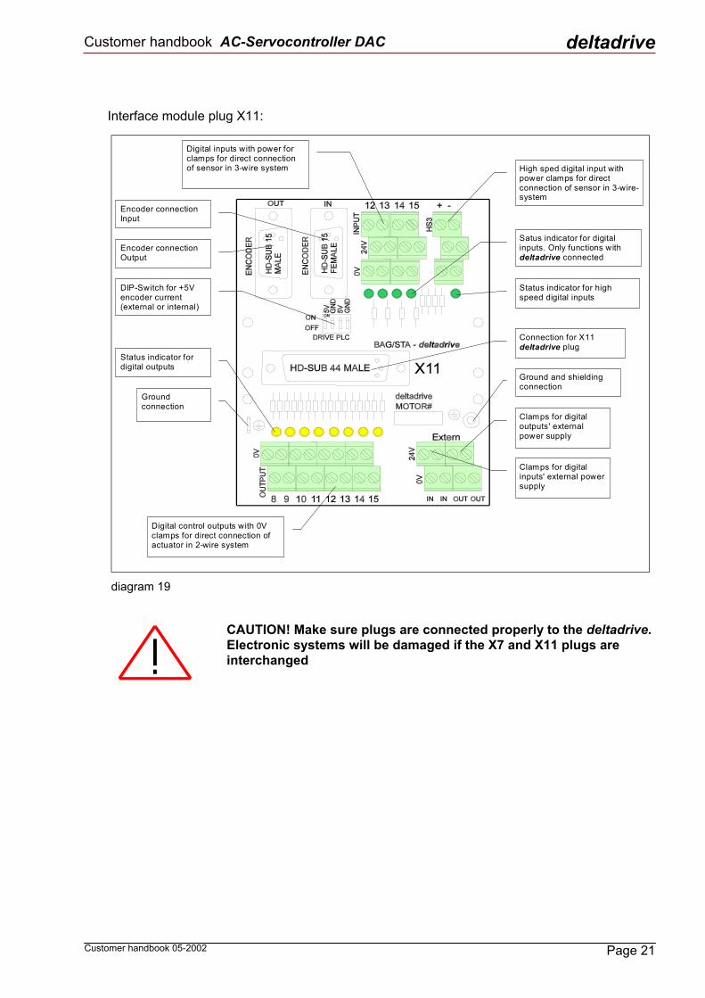
deltadrive Interface module plug X11:
Digital inputs with power forclamps for direct connectionof sensor in 3-wire system High sped digital input with
power clamps for directconnection of sensor in 3-wire-system
Satus indicator for digitalinputs. Only functions withdeltadrive connected
Status indicator for highspeed digital inputs
Connection for X11deltadrive plug
Ground and shieldingconnection
Clamps for digitaloutputs' externalpower supply
Clamps for digitalinputs' external powersupply
Digital control outputs with 0Vclamps for direct connection ofactuator in 2-wire system
Groundconnection
Status indicator fordigital outputs
DIP-Switch for +5Vencoder current(external or internal)
Encoder connectionOutput
Encoder connectionInput
diagram 19
CAUTION! Make sure plugs are connected properly to the deltadrive. Electronic systems will be damaged if the X7 and X11 plugs are interchanged
Page 21 Customer handbook 05-2002
Customer handbook AC-Servocontroller DAC deltadrive
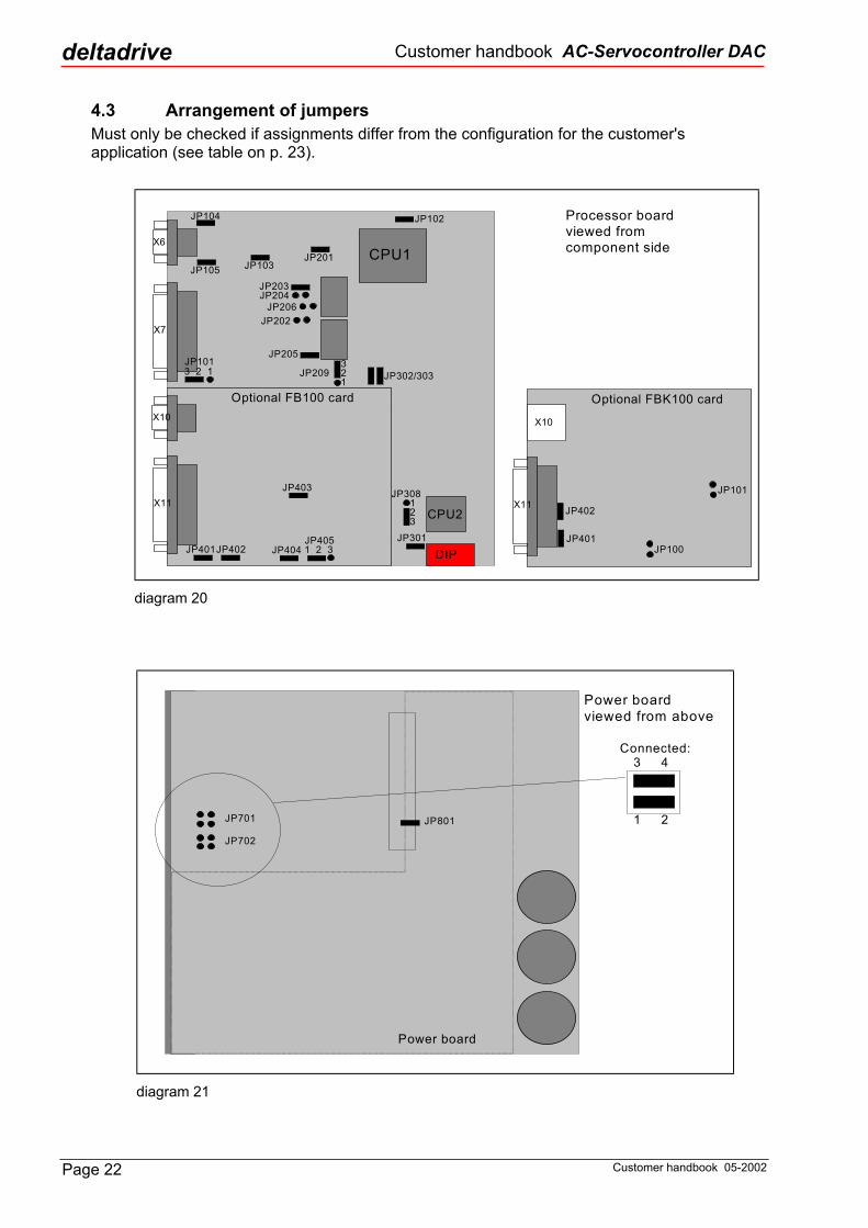
4.3 Arrangement of jumpers Must only be checked if assignments differ from the configuration for the customer's application (see table on p. 23).
Processor boardviewed fromcomponent side
JP105 JP103
JP104
JP302/303
CPU1
DIP
CPU2
X6
X7
JP201
JP102
JP203JP204
JP206JP202
JP205
JP308
JP301
Optional FB100 card
JP403
JP401JP402 JP404JP4051 2 3
X11
X10
JP1013 2 1
Optional FBK100 card
JP101
JP401
JP402
JP100
X11
X10
JP209321
123
diagram 20
JP702
JP701 JP801
3
21
4
Power boardviewed from above
Power board
Connected:
diagram 21
Page 22 Customer handbook 05-2002

Customer handbook AC-Servocontroller DAC
deltadrive Table of jumper arrangement:
Jumper Standard configuration
Customer configuration
Function
JP101 2-3 connected 1-2 connected Power output connected to internal 24 VDC supply JP102 connected Development (ext. / int. memory access) JP103 connected not connected External GND connected to internal GND JP104 connected Encoder shielding connected to internal GND JP105 connected Internal 5 V DC current for encoder connected JP201 connected ADC1 bipolar (input voltage ±10V max.) JP202 not connected Option for ADC 1/2 JP203 connected ADC2 bipolar (input voltage ±10V max.) JP204 not connected ADC2: connected. / n. con. ⇒ input voltage. ±2.5V / ±10V JP205 connected ADC3 bipolar (input voltage ±10V max.) JP206 not connected ADC3: connected. / n. con. ⇒ input voltage. ±2.5V / ±10V JP301 connected Development (ext. / int. memory access) JP302 connected Internal bus terminator for network active JP303 connected Internal bus terminator for network active JP308 2-3 connected RS232 - interrupt DSR / RI
Proc
esso
r boa
rd D
AC 1
00
JP209 2-3 connected Autom. Station address detection / PTC resistor JP701 not connected Network supply +5 VDC not connected JP702 not connected Network supply GND not connected JP801 connected GND connected to PE
Pow
er-
boar
d
JP401 connected Internal 5VDC supply for encoder connected JP402 connected External GND connected to internal GND JP403 connected not connected Control inputs' GND connected to internal GND JP404 connected not connected Outputs' GND connected to internal GND FB
100
car
d
JP405 1-2 connected External 24VDC for outputs connected JP401 connected External 5VDC supply for encoder connected JP402 connected External GND connected to internal GND JP100 not connected Processor reset inactive FB
K 10
0 ca
rd
JP101 not connected FBK programming mode inactive
4.3.1 Rearranging the jumpers The controller housing must be opened to reset the jumpers. This should only be done in consultation with the supplier; otherwise, any and all claims under the warranty become null and void.
The deltadrive controller can be disassembled as follows: • After removing the front panel, detach the heat sink baseplate from the controller housing
by removing the 8 screws. The electronics module can then be carefully separated from the housing.
• The electronic components on the printed circuit board may not be touched under any circumstances.
• After removing the attachment screws the processor board should be carefully pulled away from the connector.
• Set the jumpers correctly according to the project guide or configuration diagram and then properly reassemble the controller.
Page 23 Customer handbook 05-2002

Customer handbook AC-Servocontroller DAC deltadrive
4.4 Switch settings
Switch No. Function
ON Low speed network 1
OFF High speed network
2,3 Not used
ON Computer boots with operating system only, enable defective software to be reinstalled.
4 OFF Computer boots with application software
active (normal operation)
5,6,7,8 Not used
4.5 Automatic station address detection For automatic station address detection, a station address button is inserted into pins 13 and 14 of the X5 plug instead of a PTC temperature sensor. Table of resistance values
Station address
Resistance in ohms
1 0 2 1200 3 2200 4 3300 5 4700 6 5600 7 6800 8 8100 9 10000 10 12000 11 15000 12 18000 13 22000 14 27000 15 33000 16 39000
Front panel
ON
OFF
diagram 22
Page 24 Customer handbook 05-2002

Customer handbook AC-Servocontroller DAC
deltadrive
5. Software installation A servocontroller delivered with the standard features is only equipped with the basic software. The software for the customer's specific facility therefore has to be loaded after the controller is installed on-site. This requires an PC compatible computer with an RS232 interface and an installed deltadrive IDE (Integrated Development Environment). In addition an RS232/422 interface converter is necessary with a connector cable for the deltadrive.
5.1 Software installation with the FBK100 card • Connect plug X10 on the deltadrive to the PC's serial port (COM1 or COM2) using the
RS232/422 adapter. • Feed 24V to controller at pin 11 (24V) of plug X5 and pin 12 (GND). • Start the program DELIDE1.EXE (Windows 3.11 or Windows 95). • Load an existing project with the machine number (e.g. HZX1-4.prj) from the diskette using
the icon or the File, Open Project menu. • Select Load Project to Drives using the icon or the Loader menu. (The application software
has now been installed and saved on all controllers.) • After the files have been loaded, quit the program using File, Exit. • Important! Now turn off the machine using the main switch and wait 2 minutes. Then turn
on the main switch again. The machine is ready for operation.
d
Custom
iagram 23
Page 25 er handbook 05-2002

Customer handbook AC-Servocontroller DAC deltadrive
6. Servicing Assuming a dust / free installation, no particular servicing is required for the deltadrive. Nevertheless, and to ensure the product’s safe performance at all times, we recommend periodic servicing of your deltadrive. The examples below should be taken as recommendations. You should determine and undertake the necessary periodic service work on the basis of the application and location.
Servicing on your deltadrive should only be performed by trained professionals who observe the security and safety specifications.
The main switch or the system fuses should be switched off before any servicing. • We recommend periodic opening of the air slits in the controller housing depending on the
degree of cleanliness (or dirt) in the area of the deltadrive. • The control cabinet should be checked occasionally for the recommended operating
temperature. • Check connections periodically. • Check the motor and deltadrive for any unusual noises.
7. Trouble-shooting
7.1 Servomotor problems
7.1.1 Encoder-fails setup check If the setup check of the encoder is unsuccessful, the encoder has to be recalibrated. The motor will have to be returned to the factory for this purpose.
7.1.2 Blocked motor When the controller is switched off, it should be possible to turn the motor by hand. If this is not the case there must be a mechanical problem, either in the power train (gearing, connecting flange etc.) or in the motor. If the defect is in the motor, it will have to be returned to the factory for repairs.
7.2 Problems with the deltadrive-controller
7.2.1 Communications check If it is impossible to establish connection with the deltadrive please check the following: • If you are using an FBK100 card, verify correct connection of the RS422/232 adapter to
plug X10 on the deltadrive and to the COM1 or COM2 port of the PC. • Make sure the software driver has been correctly written into your config.sys. The following
line must be included: DEVICE=C:\DELTA\FDLDRV6.SYS PORT=1, STAD=32H, NET=1 (PORT=1 for COM1; PORT=2 for COM2; NET=1 for high speed network; NET=0 for low speed network)
Page 26 Customer handbook 05-2002

Customer handbook AC-Servocontroller DAC
deltadrive • The station address has to be consistent with the address indicated by the number of blinks
at LED3 when the deltadrive is switched on. The station address button must be inserted on pin 13, 14 of plug X5.
• Parameter checks with the MONITOR.EXE program: If the parameters are displayed, communications are in order. If the parameters window displays the "neterror" message and the station address is correctly indicated by LED3, the cable connection to the PC has to be checked again. (Caution! Leave the MONITOR.EXE program only with the "Alt-X" key combination.)
7.2.2 Controller doesn't start After the deltadrive's mains power supply is switched on, the two green LED2 and LED6 indicators should light up. If no LEDs or other LEDs light up, turn off the controller and try again. If the results are the same, the controller has to be replaced.
7.2.3 LEDs blinking on controller In this case the condition or error indicated by the displays can be determined using the table in section 3.2.4 on page 10.
7.2.4 Motor starts turning immediately If the motor starts turning as soon as the deltadrive is switched on, please check the following: • Encoder connection • The phases of the motor must be connected in the right order (for BAC and SAC motors the
sequence is as follows: motor UVW = controller WVU; cf. diagram 24). • The parameters may be incorrectly configured. Please also make sure that the motor
parameters compatible with the motor have been entered in the controller. • If all these measures fail to correct the situation, the controller must be replaced.
7.2.5 Motor vibrates If the motor starts vibrating after the controller is ready, please check the following: • The motor parameters compatible with the motor must be loaded into the controller. • The phases of the motor must be connected in the right order. • The controller parameters must be correctly set for the specific application (e.g. too high
amplification of speed regulator). • Check motor for short circuit in the coil (by measuring phase resistances) and for ground
fault.
7.2.6 Motor "whistles" If the motor emits a high-pitched tone after the controller is ready, please check the following: • The amplification of the current regulator should not be set too high.
7.2.7 Analog inputs and outputs not functioning The analog inputs and outputs are only operational when the 220V mains supply to the controller is switched on. The analog inputs and outputs cannot be used with the computer's auxiliary power supply.
Page 27 Customer handbook 05-2002

Customer handbook AC-Servocontroller DAC deltadrive
8. Connector assignments for customer's application Input Assignment X7 No. X5 No. AD1+ AD1- Shield
1 16 31
1 2 3
AD2+ AD2- Shield
2 17 32
AD3+ AD3- Shield
3 18 33
PTC+ PTC-
Ground
4 19 34
13 14
Output Assignment X7 No. X5 No. DA1 GND
14 29
DA2 GND
15 30
Output Assignment X7 No. X5 No. E0 6 4 E1 7 5 E2 8 6 E3 9 E4 10 E5 11 E6 12 E7 13 G2 39 7
Input High speed assignment X7 No. X5 No. HS1+ HS1-
5 20
HS2 GND
35 36
Output Assignment X7 No. X5 No. O0 21 8 O1 22 9 O2 23 O3 24 O4 25 O5 26 O6 27 O7 28 P2 37 10
Output Assignment X7 No. X5 No. GND 29...33,
36,38,44 3
+5V +24V +15V -15V
40 43 41 42
Power X7 No. X5 No. P1
P1GND 11
12
deltadrive
δ
Plug X7
Plug X5
Application
Customer
Project
Date
Author
Initialled
Page 28 Customer handbook 05-2002

Customer handbook AC-Servocontroller DAC
deltadrive
8.2. Additional inputs and Outputs (plug X11)
Input Assignment X11 No. E12 37 E13 39 E14 41 E15 43 GND 38 + 40
42 + 44 Input High speed assignment X11 No. HS1+ HS1-
6 21
Output Assignment X11 No. O8 8 O9 9 O10 10 O11 11 O12 12 O13 13 O14 14 O15 15 0V 22
23..29 24V 7 + 36
deltadrive
δ
Plug X11
Page 29 Customer handbook 05-2002

Customer handbook AC-Servocontroller DAC deltadrive
9. Three phase synchronous motors
9.1 Frame type references S A C 20118 M
T Y P ES A C / B A C
fram e s ize7 09 0
1 181 451 95
co re len g thKSML
sp eed [m in -1]1 20 0 - 1 22 00 0 - 2 03 00 0 - 3 04 50 0 - 4 56 00 0 - 6 0
/
o p e ra tin g vo lts3 00 V - 35 00 V - 5
3 / T B / E Y -2048 /..
c la m p b o xfo r p o w er
co n n ec tio n
o p tio n s/../..
9.2 Options BR standard brake BS brake with increased braking torque provision for: EA adaptor for ROD 426 encoder EB encoder type 35, 2048 Imp./min-1 EC adaptor for ROD 426 encoder with cover EY-2048 Encoder with rotor position detection; resolution 2048ppr FT special flange finish in accordance to din 42955 class R IP enclosure ip 67 NK shaft without key PA special paint finish to ral SE special shaft extension SS oil seal at drive end TH thermistors (without monitoring unit) VS balance to class s to din/iso 2373
Page 30 Customer handbook 05-2002

Customer handbook AC-Servocontroller DAC
deltadrive
9.3 Datasheet SAC 118M20
diagram 24
Customer handbook 05-2002
Encoder connection see diagram 10
Page 31

Customer handbook AC-Servocontroller DAC deltadrive
9.4 Datasheet SAC 90L20
d
Page
Encoder connection see diagram 10
iagram 25
32 Customer handbook 05-2002