custom-made standard type products...drill tap angle shaft (for drilling) angle shaft (for tapping)...
TRANSCRIPT
こ
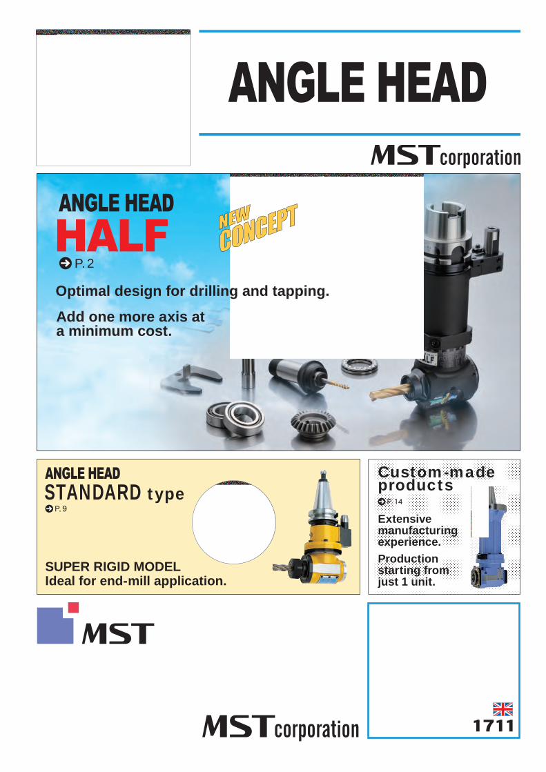
SUPER RIGID MODELIdeal for end-mill application.
1711
Add one more axis at a minimum cost.
Optimal design for drilling and tapping.
P. 14P. 9
P. 2
STANDARD typeCustom-made products
Production starting from just 1 unit.
Extensive manufacturing experience.
Angle can be set arbitrarily
2
Type CODE Q A B
90° type
HFD 7 72 68 38HFD12 98 93 58HFT 4 75 73 38HFT 6 97 92 58HFA10 90 87 38HFA20 119 111 64
HFT1297 96
64116 115
mini type HFCS6 36 31.5 31
A
B
Q For the straight pin For the taper pin
Straight pin
Adjustable pin height
Taper pin
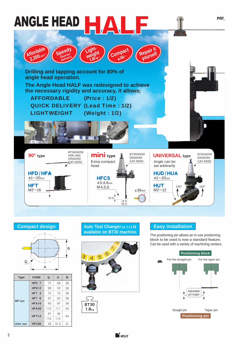
HFD / HFAφ1~20mm
HFTM2~16
BT30/40/50HSK-A63DIN40/50CAT.40/50
Auto Tool Changer (A.T.C) isavailable on BT30 machine.
BT301.8kg
㎏~
Positioning block
Positioning pin
HFD / HFA
CAT.40/50
φ36~
BT30/40/50DIN40/50CAT.40/50
������ �
120°120°
HUD / HUAφ1~20mm
HUTM2〜12
AffordableSpeedy
Shorter
deliveryLight-weight Compact
Repair it
yourself
90° type UNIVERSAL type
The positioning pin allows an in-use positioningblock to be used is now a standard feature. Can be used with a variety of machining centers.
Drilling and tapping account for 80% of angle head operation.The Angle Head HALF was redesigned to achieve the necessary rigidity and accuracy, it allows; AFFORDABLE (Price : 1/2) QUICK DELIVERY (Lead Time : 1/2) LIGHTWEIGHT (Weight : 1/2)
Compact design Easy installation
2,300USD~
15.5
31.5
HFCSφ3,4,6mmM 4,5,6
BT30/40/50DIN40/50CAT.40/50
φ36mm
type Extra-compact head
�������
���
3
Positioning block and positioning pin
■Note ●Please confirm with the machine tool manufacturer about the dimensions of the positioning block. ●We have a semi-finished positioning block with a taper hole available. →P.14
CODE HB-01
●BROTHER
●MAZAK
CODE ABF005
ROBODRILL SPEEDIOTapping center
SUPER VELOCITY CENTER
α-DiA series
2000L / 120-Ⅱ 2000L / 200-Ⅱ
■Caution ● TC-S2A※ (Tapping center),the user needs to confirm whether the positioning
block can be mounted on the machine (spindle surface) or not.● TC-R2B※(Tapping center) machining area is limited to some extent due to
interference between the positioning block and the internal part cover of the machine. For more information, please contact us.
Caution
CODE NOTEABF213 S300X1 / S500X1 / S700X1 ABF259 S1000X1
ABF176 TCーS2, S2A※, S2B, S2C, S2D, R2B※
● Available from Yamazaki Mazak Corp.
60
28 45
9
7
30
40~45HRC
S45C+0.03+0.0118
30
(14)
SPositioning block
Positioning pin
CODEContents of kit BT40-HF12-LK BT50-HF12-LK
Complete unit BT40ーHFD12ー180ーS65 (1 pc. ) BT50ーHFD12ー195ーS80 (1 pc. )Angle shaft (For tapping) FRーT6 (1 pc. )Tap sleeve TA6ー3, 4, 5, 6, 8 (each 1 pc. )DETa-1 Collet D12ー4, 6, 8, 10, 12, 13 (each 1 pc. )Positioning pin HPー50T(1 pc. ) HPー62T(1 pc. )Spare bearing 7005ADB (1 set ), 6805 (2 pcs. ), 51106 (1 pc. )
Kit Package● Learning Kit to understand gear and bearing mechanism .● There are only 22 parts and anyone can assemble them in about 10 min. ● Spare/consumable parts and assembly tools are included.
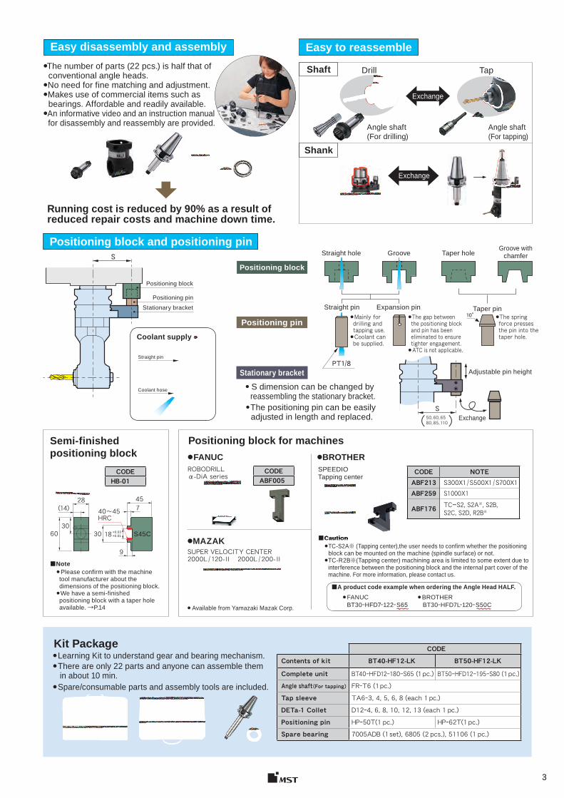
Shaft
Shank
Drill Tap
Angle shaft(For drilling)
Angle shaft(For tapping)
Exchange
Easy to reassemble
Stationary bracket
S50, 60, 6580, 85, 110( )
PT1/8
Coolant supply
■A product code example when ordering the Angle Head HALF.
BT30ーHFD7ー122ー S65 BT30ーHFD7Lー120ー S50C●FANUC ●BROTHER
Easy disassembly and assembly●The number of parts (22 pcs.) is half that of conventional angle heads.●No need for fine matching and adjustment.● Makes use of commercial items such as bearings. Affordable and readily available.● An informative video and an instruction manual for disassembly and reassembly are provided.
Positioning block
Positioning pinStationary bracket
Straight hole Groove Taper hole Groove with
chamfer
Straight pin Expansion pin Taper pin
● S dimension can be changed by reassembling the stationary bracket.
Straight pin
Coolant hose
Exchange
Adjustable pin height
Semi-finished positioning block
Positioning block for machines● FANUC
Running cost is reduced by 90% as a result of reduced repair costs and machine down time.
● The positioning pin can be easily adjusted in length and replaced. Exchange
● Mainly for drilling and tapping use. ● Coolant can be supplied.
●The gap between the positioning block and pin has been eliminated to ensure tighter engagement.●ATC is not applicable.
●The spring force presses the pin into the taper hole.
10°
4
Fig. 1 Fig. 3 Fig. 5
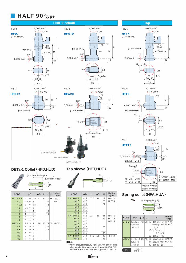
φD=1〜760
( 55 )60
( 55 )55
38 38 38
8 1.5
φ7536 36 3532 50 38
φ72 φ90
68 86 73
42 ( 46 ) 42 ( 46 )46L L
L
19 19 19
M M MφD=2.4〜10 φD=M2〜M8
( ) …HFD7L ( )…HFT4L HFD7 HFA10 HFT4
CCW 6,000 min-1
6,000 min-1
CW
Fig. 7
7862
64
8 3
L
32
M
φD=M3〜M16
61 ( M14〜M16 ) 54
115(M14〜M16)
φ116 ( M14〜M16 )42 ( M3 〜M12 )
96(M3 〜M12)
φ 97 ( M3 〜M12 )
HFT12
6,000 min-1
5,000 min-1
■ HALF 90°type
Fig. 2 Fig. 4 Fig. 6
6078
6260
5864 58
10 3
φ9748
514545
6047
φ98φ119
93111
92
L L L
29 32 29
M M M
φD=2.5〜13 φD=5.8〜20
HFD12 HFA20 HFT6
6,000 min-1 4,000 min-14,000 min-1
5,000 min-1 4,000 min-14,000 min-1
φD=M3〜M12
Drill・Endmill Tap
CCW 6,000 min-1
CCW 6,000 min-1
6,000 min-1
CW6,000 min-1
CW
CW CW CW
CW
CCW CCW CCW
CCW
D1D
H
L
(Clamping length)
D1D
H
L
(Max insertion length)(Clamping length)
H1
D1D
H
L
Ex. C10-6φD
CODE φD φD1 L H Holder type
C10ーD 2.6 2.8 3 ...(0.2 steps )... 9.6 9.8 10
17.2 26 16
18
20
(φD=2.6~5)※Except for 3, 4(φD=3, 4, 5.2~5.8)(φD=6 ~10 )
HFA10HUA10
C20ーD 6 6.2 6.4 ... (0.2 steps ) ... 19.8 20
29.5 50 323540
(φD=6~9.8)(φD=10~15.8)(φD=16~20)
HFA20HUA20
CODE φD φD1 L H H1 Holder type D 7ー 1.5 1 ~ 1.5 17 50 7 36 HFD 7
HUD 7ー 2 1.5 ~ 2 10ー 2.5 2 ~ 2.5 12ー 3 2.5 ~ 3ー 4 3 ~ 4 14ー 5 4 ~ 5 16ー 6 5 ~ 6ー 7 6 ~ 7
D12ー 4 2.5 ~ 4 26 70 16 50 HFD12ー 6 4 ~ 6 20ー 8 6 ~ 8 22ー10 8 ~ 10ー12 10 ~ 12ー13 11 ~ 13
DETa-1 Collet (HFD,HUD) Tap sleeve (HFT,HUT )
Spring collet (HFA,HUA )
■Note ● Above products meet JIS standards. We can produce other standard tap sleeves, such as ANSI, ISO, DIN and others. For more information, please contact us.
CODE φD L φD1 H Holder type
TA 4ーM 2 M 2 67.5 16 19 HFT 4HUT 4ーM 3 M 3 20
ーM 4 M 4 21ーM 5 M 5ーM 6 M 6ーM 8 M 8
TA 6ーM 3 M 3 92 19 21 HFT 6ーM 4 M 4 22 HUT 6ーM 5 M 5 HFT12ーM 6 M 6ーM 8 M 8 23ーM10 M10ーM12 M12 24
TA12ーM14 M14 111.5 25 33 HFT12ーM16 M16 35
BT40ーHFD12ー120
BT40ーHFA20ー135
BT30ーHFD7ー122
�������
���
5
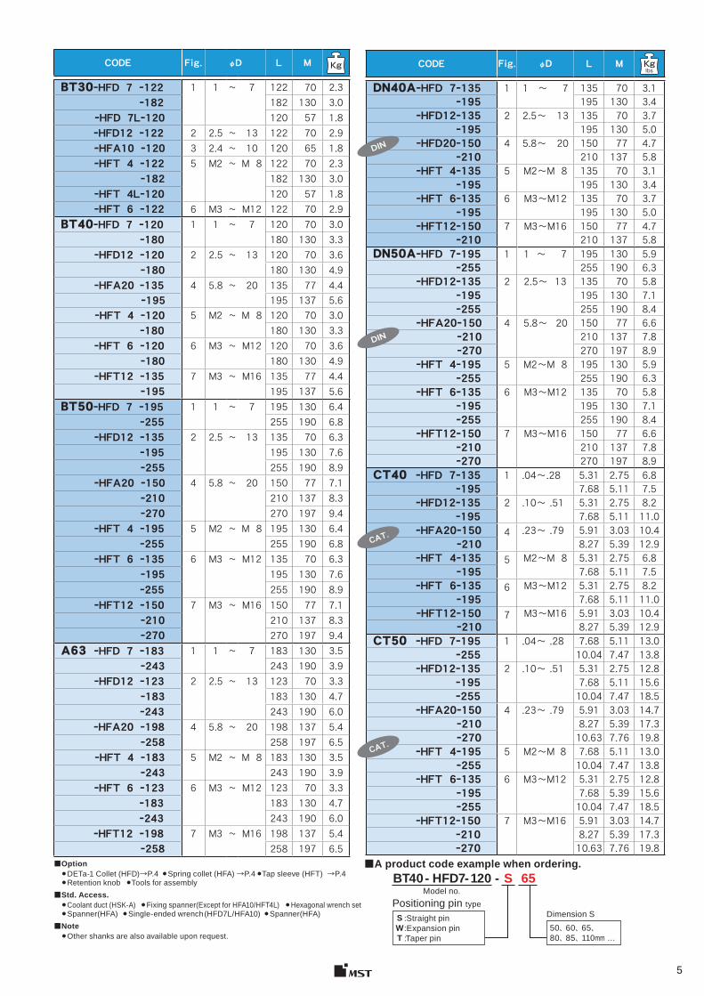
CODE Fig. φD L M
BT30ーHFD 7 ー122 1 1 ~ 7 122 70 2.3ー182 182 130 3.0
ーHFD 7Lー120 120 57 1.8ーHFD12 ー122 2 2.5 ~ 13 122 70 2.9ーHFA10 ー120 3 2.4 ~ 10 120 65 1.8ーHFT 4 ー122 5 M2 ~ M 8 122 70 2.3
ー182 182 130 3.0ーHFT 4Lー120 120 57 1.8ーHFT 6 ー122 6 M3 ~ M12 122 70 2.9
BT40ーHFD 7 ー120 1 1 ~ 7 120 70 3.0ー180 180 130 3.3
ーHFD12 ー120 2 2.5 ~ 13 120 70 3.6ー180 180 130 4.9
ーHFA20 ー135 4 5.8 ~ 20 135 77 4.4ー195 195 137 5.6
ーHFT 4 ー120 5 M2 ~ M 8 120 70 3.0ー180 180 130 3.3
ーHFT 6 ー120 6 M3 ~ M12 120 70 3.6ー180 180 130 4.9
ーHFT12 ー135 7 M3 ~ M16 135 77 4.4ー195 195 137 5.6
BT50ーHFD 7 ー195 1 1 ~ 7 195 130 6.4ー255 255 190 6.8
ーHFD12 ー135 2 2.5 ~ 13 135 70 6.3ー195 195 130 7.6ー255 255 190 8.9
ーHFA20 ー150 4 5.8 ~ 20 150 77 7.1ー210 210 137 8.3ー270 270 197 9.4
ーHFT 4 ー195 5 M2 ~ M 8 195 130 6.4ー255 255 190 6.8
ーHFT 6 ー135 6 M3 ~ M12 135 70 6.3ー195 195 130 7.6ー255 255 190 8.9
ーHFT12 ー150 7 M3 ~ M16 150 77 7.1ー210 210 137 8.3ー270 270 197 9.4
A63 ーHFD 7 ー183 1 1 ~ 7 183 130 3.5ー243 243 190 3.9
ーHFD12 ー123 2 2.5 ~ 13 123 70 3.3ー183 183 130 4.7ー243 243 190 6.0
ーHFA20 ー198 4 5.8 ~ 20 198 137 5.4ー258 258 197 6.5
ーHFT 4 ー183 5 M2 ~ M 8 183 130 3.5ー243 243 190 3.9
ーHFT 6 ー123 6 M3 ~ M12 123 70 3.3ー183 183 130 4.7ー243 243 190 6.0
ーHFT12 ー198 7 M3 ~ M16 198 137 5.4ー258 258 197 6.5
■Option ●DETa-1 Collet (HFD)→P.4 ●Spring collet (HFA) →P.4 ●Tap sleeve (HFT) →P.4●Retention knob ●Tools for assembly
■Std. Access. ●Coolant duct (HSK-A) ●Fixing spanner(Except for HFA10/HFT4L) ●Hexagonal wrench set●Spanner(HFA) ●Single-ended wrench (HFD7L/HFA10) ●Spanner(HFA)
■Note ●Other shanks are also available upon request.
BT40 - HFD7- 120 - S 65
50、 60、 65、 80、 85、 110mm …
SWT
CODE Fig. φD L M
DN40AーHFD 7ー135 1 1 ~ 7 135 70 3.1ー195 195 130 3.4
ーHFD12ー135 2 2.5~ 13 135 70 3.7ー195 195 130 5.0
ーHFD20ー150 4 5.8~ 20 150 77 4.7ー210 210 137 5.8
ーHFT 4ー135 5 M2~M 8 135 70 3.1ー195 195 130 3.4
ーHFT 6ー135 6 M3~M12 135 70 3.7ー195 195 130 5.0
ーHFT12ー150 7 M3~M16 150 77 4.7ー210 210 137 5.8
DN50AーHFD 7ー195 1 1 ~ 7 195 130 5.9ー255 255 190 6.3
ーHFD12ー135 2 2.5~ 13 135 70 5.8ー195 195 130 7.1ー255 255 190 8.4
ーHFA20ー150 4 5.8~ 20 150 77 6.6ー210 210 137 7.8ー270 270 197 8.9
ーHFT 4ー195 5 M2~M 8 195 130 5.9ー255 255 190 6.3
ーHFT 6ー135 6 M3~M12 135 70 5.8ー195 195 130 7.1ー255 255 190 8.4
ーHFT12ー150 7 M3~M16 150 77 6.6ー210 210 137 7.8ー270 270 197 8.9
CT40 ーHFD 7ー135 1 .04~.28 5.31 2.75 6.8 ー195 7.68 5.11 7.5
ーHFD12ー135 2 .10~ .51 5.31 2.75 8.2ー195 7.68 5.11 11.0
ーHFA20ー150 4 .23~ .79 5.91 3.03 10.4ー210 8.27 5.39 12.9
ーHFT 4ー135 5 M2~M 8 5.31 2.75 6.8ー195 7.68 5.11 7.5
ーHFT 6ー135 6 M3~M12 5.31 2.75 8.2ー195 7.68 5.11 11.0
ーHFT12ー150 7 M3~M16 5.91 3.03 10.4ー210 8.27 5.39 12.9
CT50 ーHFD 7ー195 1 .04~ .28 7.68 5.11 13.0ー255 10.04 7.47 13.8
ーHFD12ー135 2 .10~ .51 5.31 2.75 12.8ー195 7.68 5.11 15.6ー255 10.04 7.47 18.5
ーHFA20ー150 4 .23~ .79 5.91 3.03 14.7ー210 8.27 5.39 17.3ー270 10.63 7.76 19.8
ーHFT 4ー195 5 M2~M 8 7.68 5.11 13.0ー255 10.04 7.47 13.8
ーHFT 6ー135 6 M3~M12 5.31 2.75 12.8ー195 7.68 5.39 15.6ー255 10.04 7.47 18.5
ーHFT12ー150 7 M3~M16 5.91 3.03 14.7ー210 8.27 5.39 17.3ー270 10.63 7.76 19.8
DIN
DIN
CAT.
CAT.
■A product code example when ordering.
Positioning pin typeDimension S:Straight pin
:Expansion pin:Taper pin
Model no.
6
3, 4, 6
15.5
M4, 5, 6
L1
M
CW
31.5
L
φD=
CCW
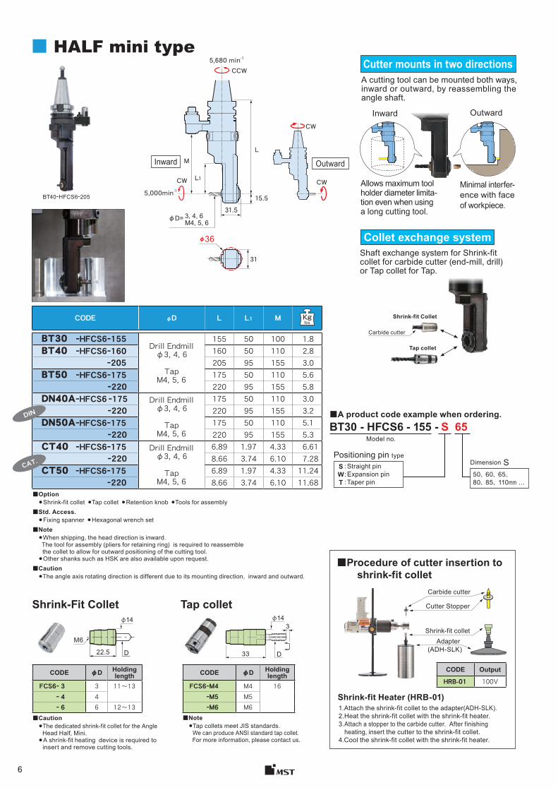
CODE φD Holding length
FCS6ー 3 3 11〜13ー 4 4ー 6 6 12〜13
CODE Output
HRB-01 100VCODE φD Holding
lengthFCS6ーM4 M4 16
ーM5 M5ーM6 M6
D22.5
φ14
M6
33
3φ14
D
BT30 - HFCS6 - 155 - S 65Model no.
50、 60、 65、 80、 85、 110mm …
SWT
CW
CW
BT40ーHFCS6ー205
5,680 min-1
5,000min-1
(ADH-SLK)
φ36
31
Carbide cutter
CODE φD L L1 M
BT30 ーHFCS6ー155Drill Endmill
φ3, 4, 6
Tap M4, 5, 6
155 50 100 1.8BT40 ーHFCS6ー160 160 50 110 2.8
ー205 205 95 155 3.0BT50 ーHFCS6ー175 175 50 110 5.6
ー220 220 95 155 5.8DN40AーHFCS6 ー175 Drill Endmill
φ3, 4, 6
Tap M4, 5, 6
175 50 110 3.0ー220 220 95 155 3.2
DN50AーHFCS6ー175 175 50 110 5.1 ー220 220 95 155 5.3
CT40 ーHFCS6ー175 Drill Endmill φ3, 4, 6
Tap M4, 5, 6
6.89 1.97 4.33 6.61 ー220 8.66 3.74 6.10 7.28
CT50 ーHFCS6ー175 6.89 1.97 4.33 11.24 ー220 8.66 3.74 6.10 11.68
DIN
CAT.
■ HALF mini typeCutter mounts in two directionsA cutting tool can be mounted both ways, inward or outward, by reassembling the angle shaft.
Inward Outward
Allows maximum tool holder diameter limita-tion even when using a long cutting tool.
Minimal interfer-ence with face of workpiece.
Collet exchange system Shaft exchange system for Shrink-fit collet for carbide cutter (end-mill, drill) or Tap collet for Tap.
Shrink-fit Collet
Tap collet
■A product code example when ordering.
Positioning pin type
: Straight pin: Expansion pin: Taper pin
Dimension S
■Option● Shrink-fit collet ●Tap collet ● Retention knob ●Tools for assembly
■Std. Access.● Fixing spanner ● Hexagonal wrench set
■Note● When shipping, the head direction is inward. The tool for assembly (pliers for retaining ring) is required to reassemble
the collet to allow for outward positioning of the cutting tool.● Other shanks such as HSK are also available upon request.
■Caution●The angle axis rotating direction is different due to its mounting direction, inward and outward.
Inward Outward
Shrink-Fit Collet Tap collet
■Caution●The dedicated shrink-fit collet for the Angle Head Half, Mini.● A shrink-fit heating device is required to insert and remove cutting tools.
■Note● Tap collets meet JIS standards.
We can produce ANSI standard tap collet. For more information, please contact us.
■Procedure of cutter insertion to shrink-fit collet
Carbide cutter
Cutter Stopper
Shrink-fit colletAdapter
Shrink-fit Heater (HRB-01)1.Attach the shrink-fit collet to the adapter(ADH-SLK).2.Heat the shrink-fit collet with the shrink-fit heater.3. Attach a stopper to the carbide cutter. After finishing
heating, insert the cutter to the shrink-fit collet.4.Cool the shrink-fit collet with the shrink-fit heater.
7
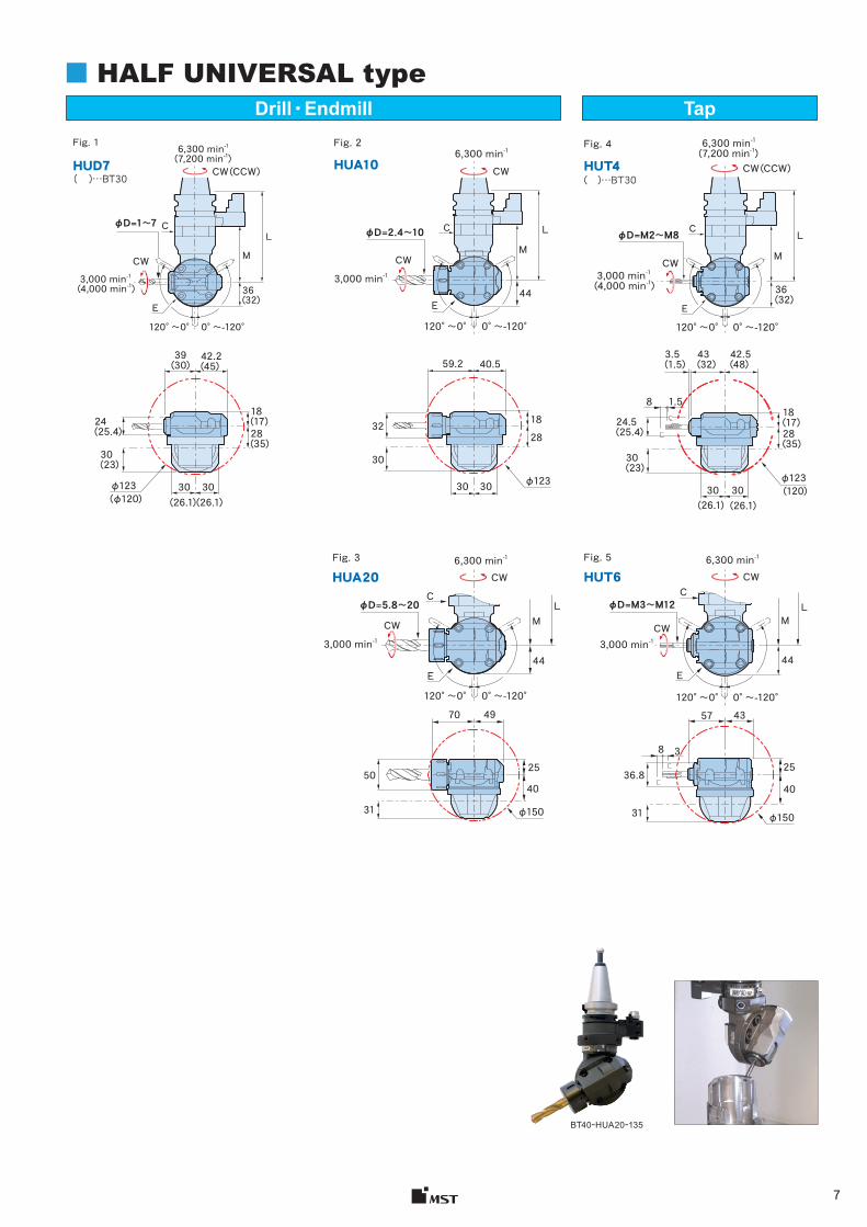
BT40ーHUA20ー135
■ HALF UNIVERSAL type
φD=1〜7
42.2(45)
39(30)
24(25.4)
φ123(φ120)
φ123 (120)
30(23)
18(17)28(35)
30 30(26.1)(26.1)
40.559.2
32 18
30
28
φ12330 30
3.5(1.5)
30 30(26.1) (26.1)
φD=M2〜M8
43(32)
42.5(48)
8 1.5
24.5(25.4)
30(23)
18(17)28(35)
3,000 min-1 (4,000 min-1)
120°〜0° 0°〜-120°
L
( )…BT30
Fig. 1
HUD7
C C
E
M
6,300 min-1(7,200 min-1)
CW (CCW)
CW
36(32)
Fig. 2
HUA10
3,000 min-1 (4,000 min-1)
( )…BT30
Fig. 4
HUT4
120°〜0° 0°〜-120°
L
MCW
6,300 min-1(7,200 min-1)
36(32)
φD=5.8〜20
4970
25
40
φ15031
50
φD=M3〜M12
43
25
40
3
57
8
φ15031
36.8
φD=2.4〜10 C��
��
��
3,000 min-1
120°〜0° 0°〜-120°
L
44E
M
6,300 min-1
CW
CW
Fig. 3
HUA20
3,000 min-1
120°〜0° 0°〜-120°
L
44
C
E
MCW
CCW
CW6,300 min-1 Fig. 5
HUT6
3,000 min-1CW
120°〜0° 0°〜-120°
LM
44E
CCW
6,300 min-1
E
CW (CCW)
Drill・Endmill Tap
8
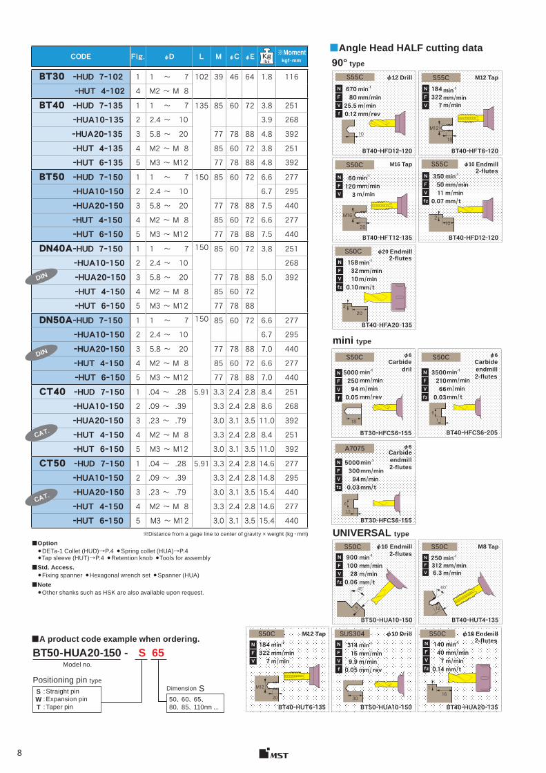
CODE Fig. φD L M φC φE ※Moment kgf・mm
BT30 ーHUD 7ー102 1 1 ~ 7 102 39 46 64 1.8 116ーHUT 4ー102 4 M2 ~ M 8
BT40 ーHUD 7ー135 1 1 ~ 7 135 85 60 72 3.8 251ーHUA10ー135 2 2.4 ~ 10 3.9 268ーHUA20ー135 3 5.8 ~ 20 77 78 88 4.8 392ーHUT 4ー135 4 M2 ~ M 8 85 60 72 3.8 251ーHUT 6ー135 5 M3 ~ M12 77 78 88 4.8 392
BT50 ーHUD 7ー150 1 1 ~ 7 150 85 60 72 6.6 277ーHUA10ー150 2 2.4 ~ 10 6.7 295ーHUA20ー150 3 5.8 ~ 20 77 78 88 7.5 440ーHUT 4ー150 4 M2 ~ M 8 85 60 72 6.6 277ーHUT 6ー150 5 M3 ~ M12 77 78 88 7.5 440
DN40AーHUD 7ー150 1 1 ~ 7 150 85 60 72 3.8 251ーHUA10ー150 2 2.4 ~ 10 268ーHUA20ー150 3 5.8 ~ 20 77 78 88 5.0 392ーHUT 4ー150 4 M2 ~ M 8 85 60 72ーHUT 6ー150 5 M3 ~ M12 77 78 88
DN50AーHUD 7ー150 1 1 ~ 7 150 85 60 72 6.6 277ーHUA10ー150 2 2.4 ~ 10 6.7 295ーHUA20ー150 3 5.8 ~ 20 77 78 88 7.0 440ーHUT 4ー150 4 M2 ~ M 8 85 60 72 6.6 277ーHUT 6ー150 5 M3 ~ M12 77 78 88 7.0 440
CT40 ーHUD 7ー150 1 .04 ~ .28 5.91 3.3 2.4 2.8 8.4 251ーHUA10ー150 2 .09 ~ .39 3.3 2.4 2.8 8.6 268ーHUA20ー150 3 .23 ~ .79 3.0 3.1 3.5 11.0 392ーHUT 4ー150 4 M2 ~ M 8 3.3 2.4 2.8 8.4 251ーHUT 6ー150 5 M3 ~ M12 3.0 3.1 3.5 11.0 392
CT50 ーHUD 7ー150 1 .04 ~ .28 5.91 3.3 2.4 2.8 14.6 277ーHUA10ー150 2 .09 ~ .39 3.3 2.4 2.8 14.8 295ーHUA20ー150 3 .23 ~ .79 3.0 3.1 3.5 15.4 440ーHUT 4ー150 4 M2 ~ M 8 3.3 2.4 2.8 14.6 277ーHUT 6ー150 5 M3 ~ M12 3.0 3.1 3.5 15.4 440
NFVfz
S50C
S55CS55C1843227
NFV
601203
NFV
18
M12
min-1mm / minm / minmm / rev
6708025.5 0.12
10
S55Cmin-1mm / minm / minmm / t
3505011 0.07
2
min-1mm / minm / min
M16 Tap
BT40ーHFT12ー135
φ10 Endmill
BT40ーHFD12ー120
φ20 Endmill
BT40ーHFA20ー135
φ12 Drill
BT40ーHFD12ー120
M12 Tap
BT40ーHFT6ー120
S50C
202
min-1mm / minm / min
φ6
BT30ーHFCS6ー155
φ6Carbide
dril
BT30ーHFCS6ー155
φ6Carbide endmill
BT40ーHFCS6ー205
S50C
A7075
min-1mm / minm / minmm / t
3500210660.03
min-1mm / minm / minmm / t
5000300940.03
S50C
min-1mm / minm / minmm / rev
5000250940.05
18
NFVfz
16
1.5
6
M12 Tap
BT40ーHUT6ー135
φ10 Drill
BT50ーHUA10ー150
φ16 Endmill
BT40ーHUA20ー135
φ10 Endmill
BT50ーHUA10ー150
M8 Tap
BT40ーHUT4ー135
S50C
S50C
S50C
SUS304
30
90010028 0.06
2503126.3
NFV
1843227
314169.9 0.05
20
M12
min-1mm / minm / min
min-1mm / minm / min mm / t
min-1mm / minm / min
min-1mm / minm / min mm / rev
S50C140407
0.14
161
min-1mm / minm / min mm / t
45°
5
60°
12
※Distance from a gage line to center of gravity × weight (kg ・ mm)
■Option●DETa-1 Collet (HUD)→P.4 ●Spring collet (HUA)→P.4●Tap sleeve (HUT)→P.4 ●Retention knob ●Tools for assembly
■Std. Access.●Fixing spanner ●Hexagonal wrench set ●Spanner (HUA)
■Note●Other shanks such as HSK are also available upon request.
DIN
DIN
CAT.
CAT.
NFVf
NFVf
NFVfz
NFVfz
NFVfz
NFVf
NFV
BT50-HUA20-150 - S 65Model no.
50、 60、 65、 80、 85、 110mm ...
SWT
■Angle Head HALF cutting data 90° type
mini type
Carbide endmill
UNIVERSAL type
■A product code example when ordering.
Positioning pin typeDimension S: Straight pin
: Expansion pin: Taper pin
M16
2010
NFVfz
1583210 0.10
min-1mm / minm / minmm / t
NFVfz
2-flutes
2-flutes
2-flutes
2-flutes
2-flutes
2-flutes
9
Type CODE Q A B
MODULAR type
AHB 5 57 46 62AHB 7 72 56 76AHB10 88 62 96
SOLID type
FLANGE type
AHA20 160 88 171AHA25 180 90 193
UNIVERSAL typeAHU10 154 55 156AHU20 188.5 70 192
A
B
Q
AHBAHC
AHAAHD
AHU
L15μmAB
L
+8
-8
μm
μm
Type CODE L
MODULAR type
AHB 5 AHB 7AHB10AHC10 40
UNIVERSAL type AHU10
SOLID type
FLANGE type
AHA20AHA25AHD30 50
UNIVERSAL type AHU20
φ0.5〜10
φ5.8〜25
φ5.8〜25
φ2.4〜20
BT40/50
BT50
φ190
BT40/50
BT40/50
F-AHAF-AHD
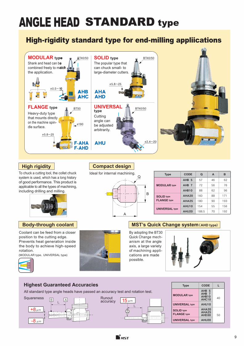
STANDARD type
High-rigidity standard type for end-milling appliications
MODULAR type SOLID type
FLANGE type UNIVERSALtype
Shank and head can be combined freely to match the application.
The popular type that can chuck small- tolarge-diameter cutters.
Heavy-duty type that mounts directly on the machine spin-dle surface.
Cutting angle can be adjusted arbitrarily.
High rigidity
MST’s Quick Change system ( AHD type)
To chuck a cutting tool, the collet chucksystem is used, which has a long history of good performance. This product is applicable to all the types of machining, including drilling and milling.
Ideal for internal machining.
Coolant can be feed from a closer position to the cutting edge.Prevents heat generation inside the body to achieve high-speed rotation.(MODULAR type、 UNIVERSAL type )
By adopting the BT30 Quick Change mech-anism at the angle axis, a large variety of machining appli-cations are made possible.
Highest Guaranteed AccuraciesAll standard type angle heads have passed an accuracy test and rotation test.
Squareness Runout accuracy
Compact design
Body-through coolant
AHBAHC
10
BT40/50typeShank and head can be combined freely to match
10
CODE Shank Head BT40ーAHB 5ー210 BT40ーMSー98 MB 5ー112
ー270 ー172ーAHB 7ー180 MB 7ー 82
ー240 ー142ーAHB10ー195 MB10ー 97
ー255 ー157ーAHC10ー230 MC10ー132
BT50ーAHB 5ー225 BT50ーMSー113 MB 5ー112ー285 ー172
ーAHB 7ー195 MB 7ー 82ー255 ー142
ーAHB10ー210 MB10ー 97ー270 ー157
ーAHC10ー245 MC10ー132
CODE Fig. φD L φC L1 M A B G φQ
BT40ーAHB 5ー210 1 0.5~ 5 210 12 20 85 25 32 46 62 5.5 ER8ー270 270 145 6.4
ーAHB 7ー180 0.5~ 7 180 19 22 60 29 43 56 76 5.3 ESX12ー240 240 120 6.6
ーAHB10ー195 2.4~10 195 36 29 80 38 50 62 96 6.2 C10ー255 255 140 7.9
ーAHC10ー230 2 230 - 110 45 32.5 65 ー 6.2BT50ーAHB 5ー225 1 0.5~ 5 225 12 20 85 25 32 46 62 8.8 ER8
ー285 285 145 9.7ーAHB 7ー195 0.5~ 7 195 19 22 60 29 43 56 76 8.6 ESX12
ー255 255 120 9.9ーAHB10ー210 2.4~10 210 36 29 80 38 50 62 96 9.5 C10
ー270 270 140 11.2ーAHC10ー245 2 245 - 110 45 32.5 65 ー 9.5
AHCAHBFig. 1 Fig. 2
Positioning pin
L L1φ95
A
B
D
S
M
φQ
CG
CM D
AB45°
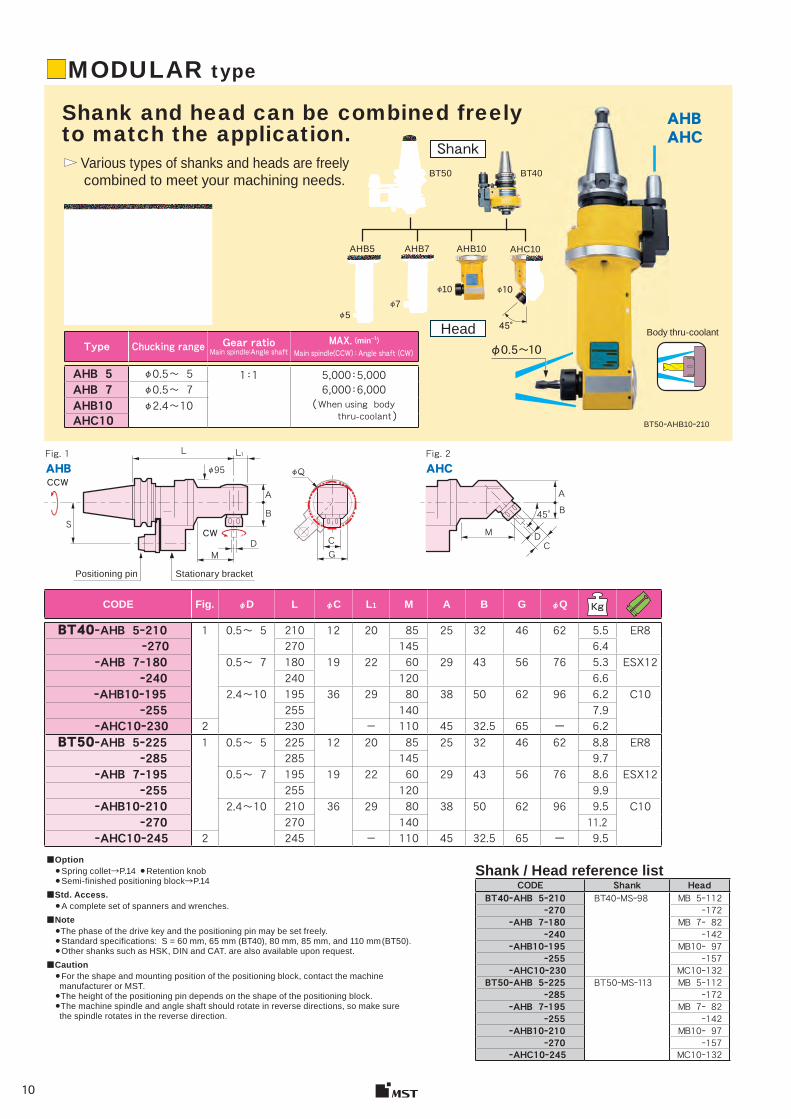
Type Chucking range Gear ratioMain spindle:Angle shaft
MAX. (min-1)Main spindle(CCW):Angle shaft(CW)
AHB 5 φ0.5~ 5 1:1 5,000:5,0006,000:6,000( When using body thru-coolant )
AHB 7 φ0.5~ 7AHB10 φ2.4~10AHC10
AHBAHC
BT50ーAHB10ー210
Body thru-coolant
φ5
BT50 BT40
φ7
φ10
AHC10AHB10AHB7AHB5
45°
φ10
Shank
Head
φ0.5〜10
■MODULAR type
Shank and head can be combined freely to match the application.
Various types of shanks and heads are freely combined to meet your machining needs.
Stationary bracket
■Option ●Spring collet →P.14 ●Retention knob ●Semi-finished positioning block →P.14
■Std. Access. ●A complete set of spanners and wrenches .
■Note ●The phase of the drive key and the positioning pin may be set freely.●Standard specifications: S = 60 mm, 65 mm (BT40), 80 mm, 85 mm, and 110 mm (BT50). ●Other shanks such as HSK, DIN and CAT. are also available upon request.
■Caution ●For the shape and mounting position of the positioning block, contact the machine manufacturer or MST. ●The height of the positioning pin depends on the shape of the positioning block.●The machine spindle and angle shaft should rotate in reverse directions, so make sure the spindle rotates in the reverse direction.
Shank / Head reference list
CW
CCW
11
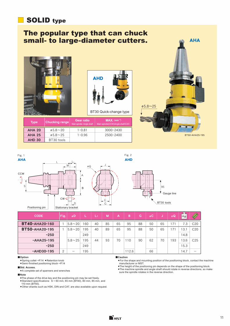
Type Chucking range Gear ratioMain spindle:Angle shaft
MAX. (min-1)Main spindle(CCW):Angle shaft(CW)
AHA 20 φ5.8〜20 1:0.81 3000:2430AHA 25 φ5.8〜25 1:0.96 2500:2400 AHD 30 BT30 tools
AHA
AHD
Fig. 1 Fig. 2
CODE Fig. φD L L1 M A B G φC J φQ
BT40ーAHA20ー160 1 5.8〜20 160 40 85 65 95 88 50 65 171 7.3 C20BT50ーAHA20ー195 1 5.8〜20 195 40 89 65 95 88 50 65 171 13.1 C20
ー250 249 14.8ーAHA25ー195 5.8〜25 195 44 93 70 110 90 62 70 193 13.6 C25
ー250 249 15.3ーAHD30ー195 2 - 195 112.6 66 14.7 -
AHDAHAL L1
M
A
BS
JφQ
CG
95
BT50ーAHA25ー195
φ5.8〜25
■■ SOLID type
The popular type that can chuck small- to large-diameter cutters.
BT30 Quick-change type
Positioning pin Stationary bracket
Gauge line
BT30 tools
■Option● Spring collet→P.14 ● Retention knob● Semi-finished positioning block→P.14
■Std. Access.● A complete set of spanners and wrenches
■Note●The phase of the drive key and the positioning pin may be set freely.● Standard specifications: S = 60 mm, 65 mm (BT40), 80 mm, 85 mm, and 110 mm (BT50).
● Other shanks such as HSK, DIN and CAT. are also available upon request.
■Caution● For the shape and mounting position of the positioning block, contact the machine manufacturer or MST.
●The height of the positioning pin depends on the shape of the positioning block.●The machine spindle and angle shaft should rotate in reverse directions, so make sure the spindle rotates in the reverse direction.
CCW
CWD
12
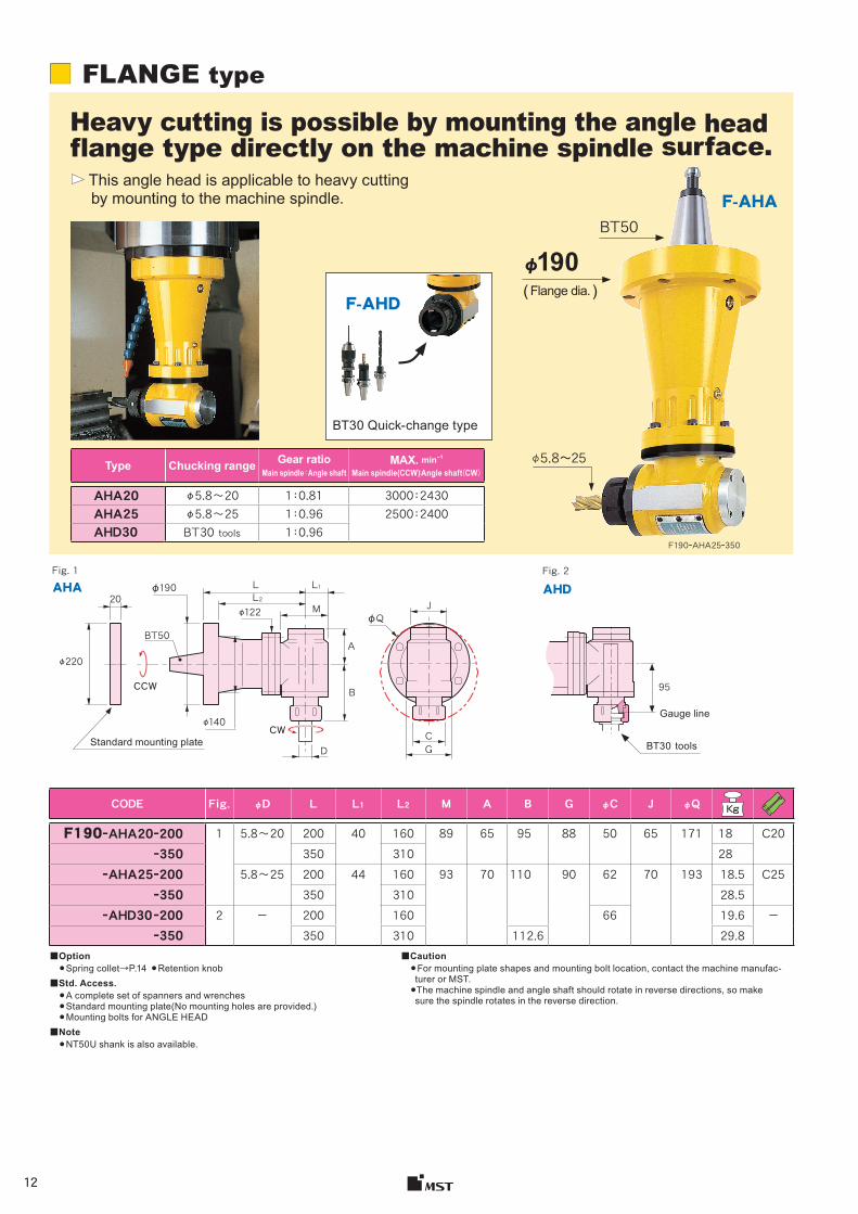
Type Chucking range Gear ratioMain spindle:Angle shaft
MAX. min-1
Main spindle(CCW):Angle shaft(CW)
AHA20 φ5.8〜20 1:0.81 3000:2430AHA25 φ5.8〜25 1:0.96 2500:2400 AHD30 BT30 tools 1:0.96
φ190BT50
F-AHD
F-AHA
Fig. 1 Fig. 2
CODE Fig. φD L L1 L2 M A B G φC J φQ Kg
F190ーAHA20ー200 1 5.8〜20 200 40 160 89 65 95 88 50 65 171 18 C20 ー350 350 310 28 ーAHA25ー200 5.8〜25 200 44 160 93 70 110 90 62 70 193 18.5 C25 ー350 350 310 28.5 ーAHD30 ー200 2 - 200 160 66 19.6 - ー350 350 310 112.6 29.8
AHDAHA20
95
GC
φQJ
BT50
φ220
φ140
D
φ122L2
M
B
A
L1Lφ190
F190ーAHA25ー350
φ5.8〜25
■■ FLANGE type
Heavy cutting is possible by mounting the angle head flange type directly on the machine spindle surface.
This angle head is applicable to heavy cutting by mounting to the machine spindle.
( Flange dia. )
BT30 Quick-change type
Standard mounting plate
Gauge line
BT30 tools
■Option● Spring collet→P.14 ● Retention knob
■Std. Access.● A complete set of spanners and wrenches● Standard mounting plate(No mounting holes are provided.)● Mounting bolts for ANGLE HEAD
■Note● NT50U shank is also available.
■Caution● For mounting plate shapes and mounting bolt location, contact the machine manufac-turer or MST.
●The machine spindle and angle shaft should rotate in reverse directions, so make sure the spindle rotates in the reverse direction.
CW
CCW
�������
���
13
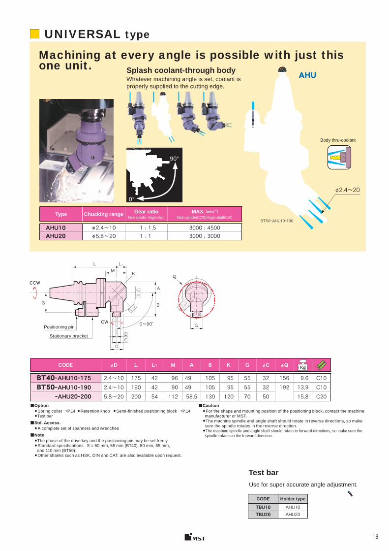
90°
0°
Type Chucking range Gear ratioMain spindle:Angle shaft
MAX. (min-1)Main spindle(CCW):Angle shaft(CW)
AHU10 φ2.4~10 1 : 1.5 3000 : 4500AHU20 φ5.8~20 1 : 1 3000 : 3000
CODE Holder type
TBU10 AHU10TBU20 AHU20
AHU
CODE φD L L1 M A B K G φC φQ Kg
BT40ーAHU10ー175 2.4~10 175 42 96 49 105 95 55 32 156 9.6 C10BT50ーAHU10ー190 2.4~10 190 42 90 49 105 95 55 32 192 13.9 C10 ーAHU20ー200 5.8~20 200 54 112 58.5 130 120 70 50 15.8 C20
L
S
CD
0〜90°
B
A
KML1
Q
G
BT50ーAHU10ー190
φ2.4〜20
■ UNIVERSAL type
Machining at every angle is possible with just this one unit. Splash coolant-through body
Whatever machining angle is set, coolant is properly supplied to the cutting edge.
Body thru-coolant
Positioning pin
Stationary bracket
■Option ●Spring collet →P.14 ●Retention knob ●Semi-finished positioning block →P.14●Test bar
■Std. Access. ●A complete set of spanners and wrenches
■Note ●The phase of the drive key and the positioning pin may be set freely. ●Standard specifications: S = 60 mm, 65 mm (BT40), 80 mm, 85 mm, and 110 mm (BT50).●Other shanks such as HSK, DIN and CAT. are also available upon request.
■Caution ●For the shape and mounting position of the positioning block, contact the machine manufacturer or MST. ●The machine spindle and angle shaft should rotate in reverse directions, so make sure the spindle rotates in the reverse direction. ●The machine spindle and angle shaft should rotate in forward directions, so make sure the spindle rotates in the forward direction.
Test bar Use for super accurate angle adjustment.
CCW
CW
G
14
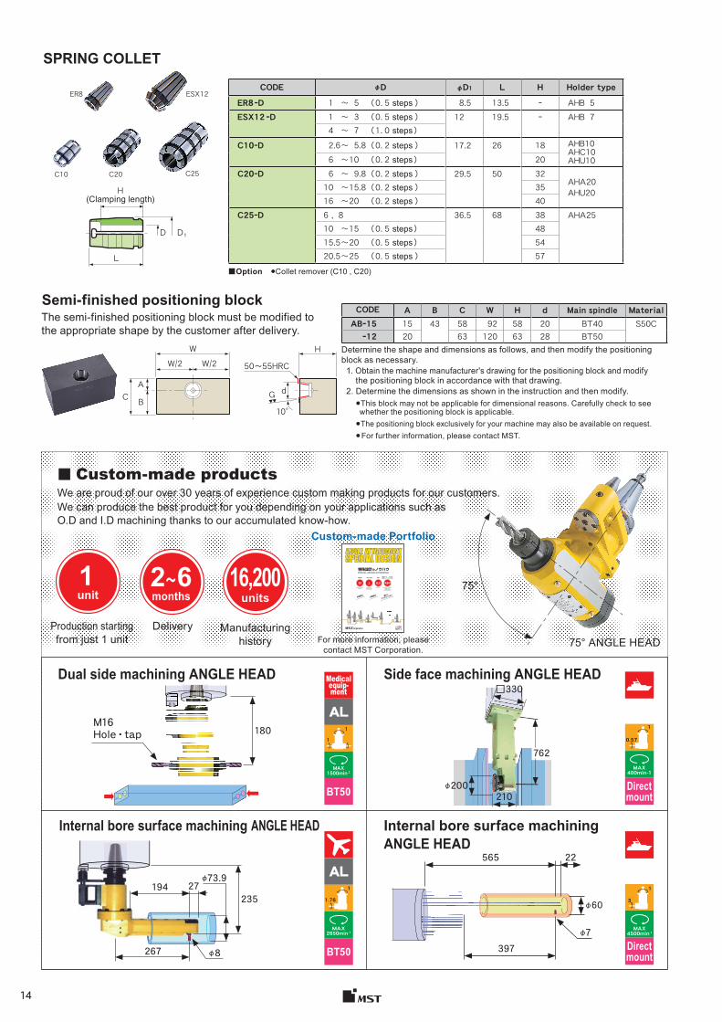
CODE φD φD1 L H Holder typeER8ーD 1 〜 5 ( 0.5 steps ) 8.5 13.5 ー AHB 5ESX12 ーD 1 〜 3 ( 0.5 steps ) 12 19.5 ー AHB 7
4 〜 7 ( 1.0 steps )C10ーD 2.6〜 5.8( 0.2 steps ) 17.2 26 18 AHB10
AHC10AHU106 〜10 ( 0.2 steps ) 20
C20ーD 6 〜 9.8( 0.2 steps ) 29.5 50 32AHA20AHU2010 〜15.8( 0.2 steps ) 35
16 〜20 ( 0.2 steps ) 40 C25ーD 6 , 8 36.5 68 38 AHA25
10 〜15 ( 0.5 steps ) 4815.5〜20 ( 0.5 steps ) 54 20.5〜25 ( 0.5 steps ) 57
CODE A B C W H d Main spindle Material ABー15 15 43 58 92 58 20 BT40 S50C
ー12 20 63 120 63 28 BT50
The semi-finished positioning block must be modified to the appropriate shape by the customer after delivery.
ER8 ESX12
C25C20C10
D D1
L
WW/2 W/2
CA
H
10°B
G d
50〜55HRC
ANGLE ATTACHMENT SPECIAL DESIGN
特殊設計のノウハウ
1211JE
SPECIAL DESIGN EXPERIENCE
30years
1unit
3~6months
12,800units
Manufacturing History
DeliveryProduction starting from just 1 unit
Specially designed 670 units
Standard type12,130 units
1台 から製造 納期製造実績特殊タイプ 670台標準タイプ 12,130台
内面加工 様々
な
アプリケーシ
ョン外周加工
Internal ma
chining
Various
kinds o
f applicatio
ns
External m
achining
75°1unit
2~6months
16,200units
AL
Medicalequip-ment
1
1
BT50
MAX1500min-1
Internal bore surface machining ANGLE HEAD Internal bore surface machiningANGLE HEAD
Side face machining ANGLE HEAD
180 1
0.57
MAX400min-1
AL1
1.76
MAX2650min-1
BT50
1
3
MAX4500min-1
Directmount
210
□330
φ200
762
Determine the shape and dimensions as follows, and then modify the positioning block as necessary.
SPRING COLLET
■Option ●Collet remover (C10 , C20)
Semi-finished positioning block
1. Obtain the machine manufacturer's drawing for the positioning block and modify the positioning block in accordance with that drawing. 2. Determine the dimensions as shown in the instruction and then modify.
●This block may not be applicable for dimensional reasons. Carefully check to see whether the positioning block is applicable.
●The positioning block exclusively for your machine may also be available on request.● For further information, please contact MST.
H(Clamping length )
■■ Custom-made productsWe are proud of our over 30 years of experience custom making products for our customers. We can produce the best product for you depending on your applications such as O.D and I.D machining thanks to our accumulated know-how.
Production starting from just 1 unit
Delivery Manufacturing history For more information, please
contact MST Corporation.75° ANGLE HEAD
Dual side machining ANGLE HEAD
M16Hole ・ tap
Directmount
Custom-made Portfolio
φ73.9
235194
φ8
27
267
φ60
565 22
φ7397
アアアアアアア
アアア
15
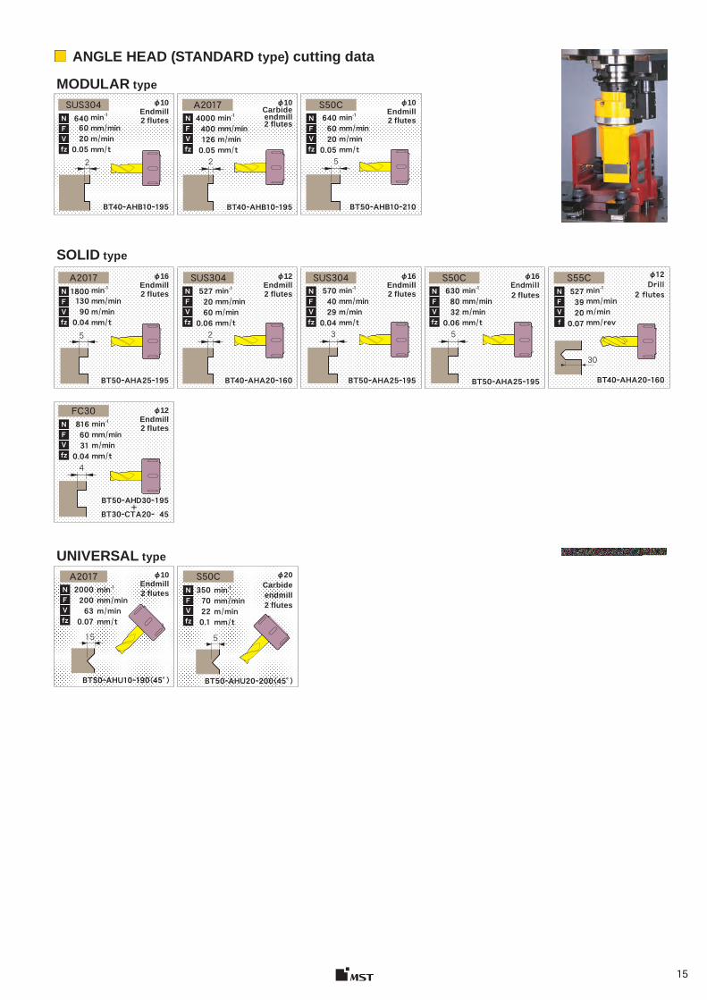
φ10 Endmill 2 flutes
BT40ーAHB10ー195
φ10 Carbide endmill2 flutes
BT40ーAHB10ー195
φ10 Endmill 2 flutes
BT50ーAHB10ー210
SUS304min-1mm / minm / minmm / t
64060200.05
NFVfz
2
A2017min-1mm / minm / minmm / t
40004001260.05
NFVfz
2
S50Cmin-1mm / minm / minmm / t
64060200.05
NFVfz
5
φ10 Endmill 2 flutes
BT50ーAHU10ー190 (45° )
φ20 Carbide endmill 2 flutes
BT50ーAHU20ー200 (45°)
A2017min-1mm / minm / minmm / t
2000200630.07
15
min-1mm / minm / minmm / t
35070220.1
NFVfz
5
φ16 Endmill 2 flutes
BT50ーAHA25ー195
φ12 Endmill 2 flutes
BT40ーAHA20ー160
φ16 Endmill 2 flutes
BT50ーAHA25ー195
φ16 Endmill 2 flutes
BT50ーAHA25ー195
φ12 Drill
2 flutes
BT40ーAHA20ー160
φ12 Endmill 2 flutes
BT50ーAHD30ー195+
BT30ーCTA20ー 45
A2017min-1mm / minm / minmm / t
1800130900.04
NFVfz
5
SUS304min-1mm / minm / minmm / t
52720600.06
NFVfz
2
SUS304min-1mm / minm / minmm / t
57040290.04
NFVfz
NFVfz
3
S50C
S50C
FC30
min-1mm / minm / minmm / t
63080320.06
NFVfz
5
S55C
30
min-1mm / minm / minmm / rev
52739200.07
NFVf
min-1mm / minm / minmm / t
81660310.04
NFVfz
4
■ ANGLE HEAD (STANDARD type) cutting data
MODULAR type
SOLID type
UNIVERSAL type
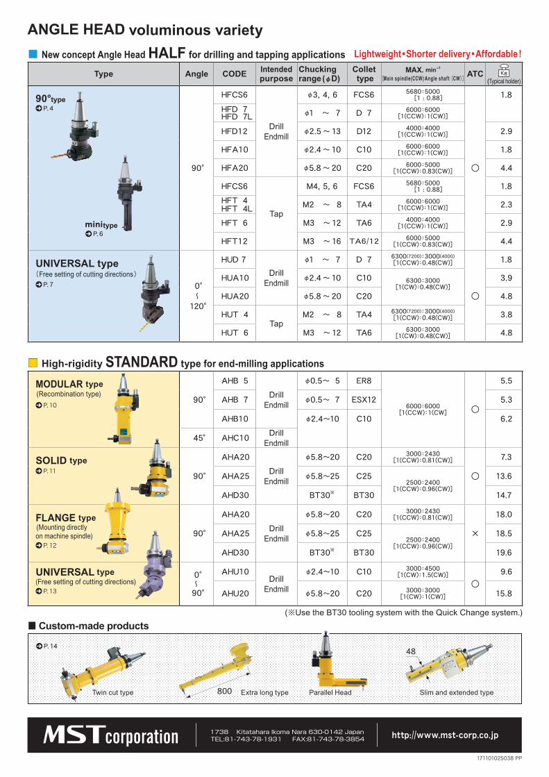
Type Angle CODE Intended purpose
Chucking range (φD)
Collet type
MAX. min-1 [Main spindle(CCW):Angle shaf t (CW)] ATC
(Typical holder)
90°type P. 4
90°
HFCS6
Drill Endmill
φ3, 4, 6 FCS6 5680:5000 [1 : 0.88]
○
1.8HFD 7HFD 7L φ1 〜 7 D 7 6000:6000
[1(CCW):1(CW)]
HFD12 φ2.5 〜 13 D12 4000:4000[1(CCW):1(CW)] 2.9
HFA10 φ2.4 〜 10 C10 6000:6000[1(CCW):1(CW)] 1.8
HFA20 φ5.8 〜 20 C20 6000:5000[1(CCW):0.83(CW)] 4.4
HFCS6
Tap
M4, 5, 6 FCS6 5680:5000 [1 : 0.88] 1.8
HFT 4HFT 4L M2 〜 8 TA4 6000:6000
[1(CCW):1(CW)] 2.3
HFT 6 M3 〜 12 TA6 4000:4000[1(CCW):1(CW)] 2.9
HFT12 M3 〜 16 TA6/12 6000:5000[1(CCW):0.83(CW)] 4.4
UNIVERSAL type ( Free setting of cutting directions ) P. 7 0°
〜 120°
HUD 7Drill
Endmill
φ1 〜 7 D 7 6300(7200):3000(4000)[1(CCW):0.48(CW)]
○
1.8
HUA10 φ2.4 〜 10 C10 6300:3000[1(CW):0.48(CW)]
3.9
HUA20 φ5.8 〜 20 C20 4.8
HUT 4Tap
M2 〜 8 TA4 6300(7200):3000(4000)[1(CCW):0.48(CW)] 3.8
HUT 6 M3 〜 12 TA6 6300:3000[1(CW):0.48(CW)] 4.8
MODULAR type (Recombination type)
P. 10 90°
AHB 5Drill
Endmill
φ0.5〜 5 ER8
6000:6000[1(CCW):1(CW] ○
5.5
AHB 7 φ0.5〜 7 ESX12 5.3
AHB10 φ2.4〜10 C10 6.2
45° AHC10 Drill Endmill
SOLID type P. 11 90°
AHA20Drill
Endmill
φ5.8〜20 C20 3000:2430[1(CCW):0.81(CW)]
○
7.3
AHA25 φ5.8〜25 C252500:2400
[1(CCW):0.96(CW)]
13.6
AHD30 BT30※ BT30 14.7
FLANGE type (Mounting directly on machine spindle)
P. 1290°
AHA20Drill
Endmill
φ5.8〜20 C20 3000:2430[1(CCW):0.81(CW)]
×
18.0
AHA25 φ5.8〜25 C252500:2400
[1(CCW):0.96(CW)]
18.5
AHD30 BT30※ BT30 19.6
UNIVERSAL type (Free setting of cutting directions)
P. 13
0°〜90°
AHU10Drill
Endmill
φ2.4〜10 C10 3000:4500[1(CW):1.5(CW)]
○9.6
AHU20 φ5.8〜20 C20 3000:3000[1(CW):1(CW)] 15.8
800 Extra long type
48
P. 6minitype
■ New concept Angle Head HALF for drilling and tapping applications
(※Use the BT30 tooling system with the Quick Change system.)
P. 14
Lightweight • Shorter delivery • Affordable !
voluminous variety
■ High-rigidity STANDARD type for end-milling applications
■ Custom-made products
Twin cut type Parallel Head Slim and extended type
ANGLE HEAD
http://www.mst-corp.co.jp
171101025038 PP