custom dynamics® led tri bar fender tip installation ... · pleted, test the led tri-bar light in...
TRANSCRIPT

Custom Dynamics® LED Tri-Bar Fender Tip Installation Instructions
We thank you for purchasing the Custom Dynamics® LED Tri-Bar
Fender Tip! Our products utilize the latest technology and high
quality components to ensure you the most reliable service. We
offer one of the best warranty programs in the industry and we
back our products with excellent customer support, if you have
questions before or during installation of this product please call
Custom Dynamics® at 1(800) 382-1388.
Questions? Call us at: 1 (800) 382-1388 M-TH 8:30AM-5:30PM / FR 9:30AM-5:30PM EST
10-2017
Package Contents:
- Tri-Bar Light Assembly (1)
- Smart Triple Play (1)
- 4” Black Tie Wrap (10)
Fits: 2010-2013 US Model Harley-Davidson® Street Glide®
and Road Glide® Custom with required 6 Pin SMART Signal
Stabilizer™ installed
1. Remove the hard saddlebags from the bike to allow access to the underside of the fender.
2. Remove the black cover on the back side of the tri-bar light and discard. Once removed, locate the clip just above
the tri-bar that holds the wire harness in place. Remove the 7/16 nut then remove the clip from the harness. This
allows easy removal of the wires from the tri-bar. Keep clip and nut handy for re-installation later.
3. Unplug the connectors from both sides of the tri-bar.
4. Remove the 2 Torx T25 screws that hold the stock tri-bar assembly in place. Remove the screws and save for in-
stalling the new unit.
6. Slowly pull the tri-bar away from the fender, making sure that the wiring and connectors are free as well. Once re-
moved, discard.
7. Install the LED tri-bar into the fender, make sure everything is aligned, then fasten down with the T25 Torx screws
saved from the old unit.
8. Plug the harness connectors into the new Tri-Bar, noting the rectangular ports on the back side to the unit. Left side
should be going to the bike, the right side is the output to the turn signals. Make sure that the connector orientation
is correct going into the ports, they are keyed one way, if the connector does not want to snap in, flip it around and
try it again. Do not force the connector into the port.
9. Re-install the Clip to the bike’s wiring harness, then re-attach the clip to the fender with the 7/16” nut.
10. Install the SS6 Smart Triple Play. (See Specific instructions and features for module on page 3) If you are using
these products with regular incandescent bulbs, You will also need to install a Signal Stabilizer or equivalent load
equalizer, contact us if you do not have one. If you are already using Custom Dynamics® LED turn signals you may
already have our Signal Stabilizer™ Installed.
11. Once all products are installed, turn bike on and test function of the Smart TPU. It is recommended you set the
brightness of the turn signals in program mode (see page 4) before testing all functions. Once programming is com-
pleted, test the LED tri-bar light in running and brake modes. Also check function of the turn signals to make sure
Smart TPU is functioning properly.
Proper orientation of the harness connectors is
important, make sure you have input coming from
the bike and output going to the turn signals. Check
for the notch cut outs in the connectors to ensure
proper alignment before plugging in.
Part Number: GEN2-TRI-2
Tri-Bar Installation

Installation Instructions - Page 2
Questions? Call us at: 1 (800) 382-1388 M-TH 8:30AM-5:30PM / FR 9:30AM-5:30PM EST
10-2017
Input Harness
(Left Side) From Bike
Output Harness
(Right Side) To Turn Signals
Output Connector Input Connector
LED Tri-Bar Diagram
Plug the harness connectors into the new Tri-Bar,
noting the rectangular ports on the back side to
the unit. Left side should be going to the bike, the
right side is the output to the turn signals. Make
sure that the connector orientation is correct going
into the ports, they are keyed one way, if the con-
nector does not want to snap in, flip it around and
try it again.
Note: The connector should not be forced into the
port. Doing so can cause bending of the internal
pins which is not covered under warranty.
Harness Port—Input Connector
Harness Ports
Smart Triple Play® (US Patent 8,588,997) Installation Instructions– page 3
Questions? Call us at: 1 (800) 382-1388 M-TH 8:30AM-5:30PM / FR 9:30AM-5:30PM EST
10-2017
This Module is for 2010-2013 Street Glides with Stock
rear fender when converting to our LED Tri-bar only.
Please Note: The Smart Triple Play® provided in this kit will re-
quire the use of a Signal Stabilizer module even when used with
stock incandescent bulb turn signals.
Important: A load Equalizer or Signal Stabilizer™ is required for
the Smart Triple Play® to function properly. These units MUST be
installed in the input side before the Smart Triple Play® inline.
Caution: Never install a Load Equalizer Downstream of this unit.
Caution: Never install a trailer adapter, trailer harness or trailer
controller downstream of this unit, a trailer adapter, harness or
controller must be installed on the input side of this unit.
Caution: This unit is designed for a maximum load of 27 watts per
channel. Do not exceed 27 watts per left turn signal output, 27
watts per right turn signal output, and 27 watts per brake signal
output. Overloading unit could cause damage to the unit and
cause the unit to malfunction.
Important: Module must be secured after installation. Find safe
area away from any moving parts and out of the way of normal
operation of the bike. Use Tie-wraps, tape, or other means to se-
cure. Custom Dynamics® is not liable for damage to the module or
the bike as a result of improper securing.
1. Secure motorcycle on level surface. Remove the
kickstand side panel. Disconnect negative bat-
tery cable from the battery. Locate and unplug
the lighting connector to the rear fender.
2. Plug the Smart Triple Play® Module, in-line, into
the rear lighting harness and into the bike’s wiring
harness. Secure Module.
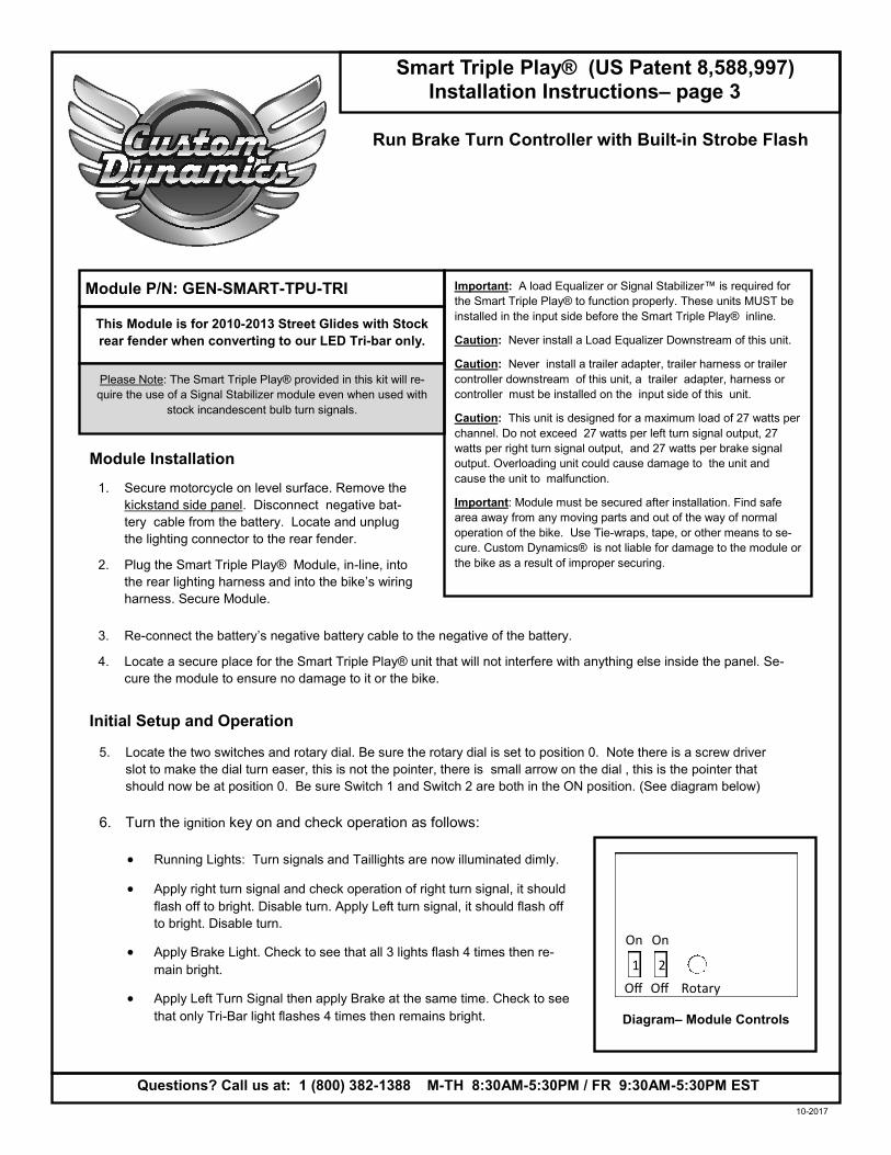
5. Locate the two switches and rotary dial. Be sure the rotary dial is set to position 0. Note there is a screw driver
slot to make the dial turn easer, this is not the pointer, there is small arrow on the dial , this is the pointer that
should now be at position 0. Be sure Switch 1 and Switch 2 are both in the ON position. (See diagram below)
3. Re-connect the battery’s negative battery cable to the negative of the battery.
4. Locate a secure place for the Smart Triple Play® unit that will not interfere with anything else inside the panel. Se-
cure the module to ensure no damage to it or the bike.
6. Turn the ignition key on and check operation as follows:
• Running Lights: Turn signals and Taillights are now illuminated dimly.
• Apply right turn signal and check operation of right turn signal, it should
flash off to bright. Disable turn. Apply Left turn signal, it should flash off
to bright. Disable turn.
• Apply Brake Light. Check to see that all 3 lights flash 4 times then re-
main bright.
• Apply Left Turn Signal then apply Brake at the same time. Check to see
that only Tri-Bar light flashes 4 times then remains bright.
Run Brake Turn Controller with Built-in Strobe Flash
Off Off
On On
1 2
Rotary
Diagram– Module Controls
Module P/N: GEN-SMART-TPU-TRI
Module Installation
Initial Setup and Operation
Smart Triple Play® (US Patent 8,588,997) Installation Instructions– page 4
Questions? Call us at: 1 (800) 382-1388 M-TH 8:30AM-5:30PM / FR 9:30AM-5:30PM EST
10-2017
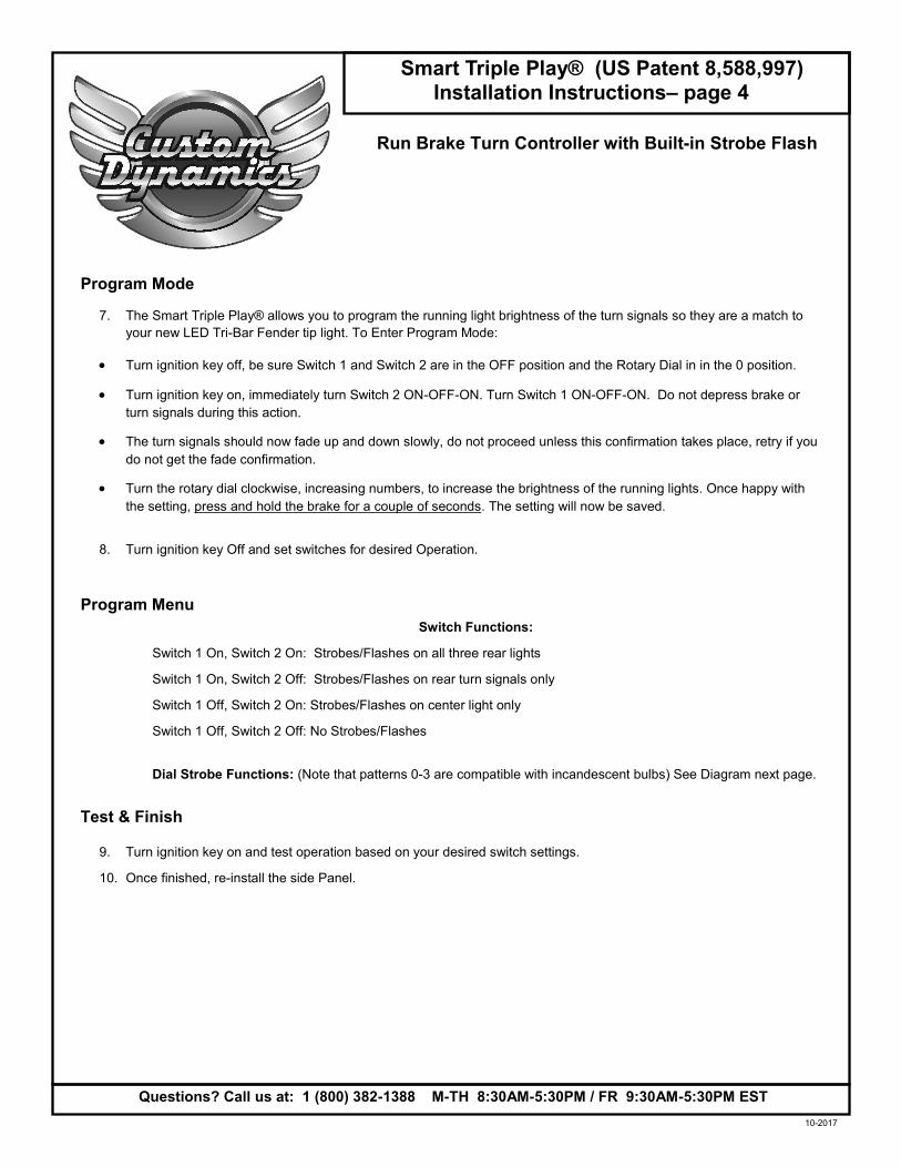
• Turn ignition key off, be sure Switch 1 and Switch 2 are in the OFF position and the Rotary Dial in in the 0 position.
• Turn ignition key on, immediately turn Switch 2 ON-OFF-ON. Turn Switch 1 ON-OFF-ON. Do not depress brake or
turn signals during this action.
• The turn signals should now fade up and down slowly, do not proceed unless this confirmation takes place, retry if you
do not get the fade confirmation.
• Turn the rotary dial clockwise, increasing numbers, to increase the brightness of the running lights. Once happy with
the setting, press and hold the brake for a couple of seconds. The setting will now be saved.
8. Turn ignition key Off and set switches for desired Operation.
Switch Functions:
Switch 1 On, Switch 2 On: Strobes/Flashes on all three rear lights
Switch 1 On, Switch 2 Off: Strobes/Flashes on rear turn signals only
Switch 1 Off, Switch 2 On: Strobes/Flashes on center light only
Switch 1 Off, Switch 2 Off: No Strobes/Flashes
Dial Strobe Functions: (Note that patterns 0-3 are compatible with incandescent bulbs) See Diagram next page.
9. Turn ignition key on and test operation based on your desired switch settings.
10. Once finished, re-install the side Panel.
7. The Smart Triple Play® allows you to program the running light brightness of the turn signals so they are a match to
your new LED Tri-Bar Fender tip light. To Enter Program Mode:
Run Brake Turn Controller with Built-in Strobe Flash
Program Mode
Program Menu
Test & Finish

Installation Instructions - Page 5
Questions? Call us at: 1 (800) 382-1388 M-TH 8:30AM-5:30PM / FR 9:30AM-5:30PM EST
10-2017
Flash Pattern Information
8
0 1 9
2
4
3
6 5
7
Pattern 0: Four Flashes then Solid
Pattern 1: Four Flashes, Solid for 3
Seconds, Repeat
Pattern 2: Seven Flashes then
Solid
Pattern 3: Seven Flashes, Solid for
3 Seconds, Repeat
Pattern 4: Quad Strobe then Solid
for 1 Second then Quad Strobe
Pattern 5: Quad Strobe, Solid for 1 Second,
then Quad Strobe, Solid for 3 Seconds, then
Repeat
Pattern 6: Blaster X Pattern for 3
seconds, then Solid
Pattern 7: Constant Blaster X Pattern
Pattern 8: Constant Fast Strobe 5
Seconds, then Solid
Pattern 9: Constant Fast Strobe Pattern
Incandescent or LED
Incandescent or LED
Incandescent or LED
Incandescent or LED
LED Only
LED Only
LED Only
LED Only
LED Only
LED Only
Rear of Bike
Signal Stabilizer™
or load Equalizer
Smart Triple Play ™
Front of Bike
Correct Placement of Smart Triple Play™ is after Signal Stabilizer™ or Load EQ
Incorrect installation - Wrong Location is before Stabilizer or Load EQ
Rear of Bike
Front of Bike
Front of Bike
Module Placement
Smart Triple Play ™
Signal Stabilizer™
or load Equalizer