cushcraft ma6b six-band minibeam · cushcraft ma6b six-band minibeam parts inventory: as you...
TRANSCRIPT
Cushcraft MA6B Six-Band MiniBeam Parts Inventory: As you unpack, identify and check off each item against the Master Parts List on the next page. This important step will familiarize you with the various parts and confirm that you have everything needed to complete construction. If any element tubes appear to be missing, check inside other larger tubes. Marking each tube as you inventory—it will speed assembly later, as will sorting the hardware. Save the weight label attached to the carton. If you claim a missing part, the label has information you'll need to provide! Planning: Plan assembly carefully – the work area must be large enough to handle the 10-foot boom and elements up to 18-feet long. Also, the antenna will need to be supported off the ground when installing the capacitive-hat rods (sawhorses work well). Trap vents will be exposed the weather during assembly, so cover them if it rains. Finally, proceed methodically, allow plenty of time, and always have one or more helpers available to assist with the final installation! Important Warning: Never attempt to install the MA6B by yourself! Antenna Location: To realize the best on-air performance, mount the MA6B as high and in the clear as safety permits -- and remove all vegetation and tree branches from the area. If you guy the support mast near the antenna, be sure to use Phillystran cord or an equivalent non-conductor to prevent detuning. Finally, never install where the antenna could fall and hit power lines, where people or animals could accidentally come into physical contact with the elements, or where humans could be exposed to high-intensity RF-fields. See the ARRL Handbook or FCC website for detailed RF exposure information and guidelines. Important Safety Warnings: Never assemble or install this antenna where it could contact power lines or residential entrance cables -- you could be killed! Also, when the MA6B is energized with RF, touching the elements could cause painful injury from RF burns – even at low power levels. Finally, never install where humans could become chronically exposed to high-intensity RF fields. Mast: The MA6B mounting bracket accepts masts up to 2 inches in diameter. For safety reasons, the minimum diameter should be at least 1-1/2 inches with 1/8-inch wall thickness. If thick-wall tubing is unavailable, use two 1/16-inch-wall tubes telescoped together. Note that the structure supporting your mast must be able to support the 33-pound antenna plus the added weight of your mast and rotor. Safely Ground: All towers and masts require a safety ground to help protect against lightning strikes and static build up. Where possible, drive one or more ground rods directly underneath the antenna and use solid 10-gauge wire secured with non-corrosive hardware for all connections. Note that the MA6B driven elements are balanced and have no direct dc path to ground, so installing a coaxial lightning arrestor is also a good idea. Of course, the best protection of all is to disconnect all feedlines outside of the building any time the station is not in use or at the first sign of threatening weather!
MA6B Parts List: [X] Quan Part # Description . [ ] 2 MT1 21/28 MHz driven element trap assembly [ ] 4 MT2 24.9 MHz trap assembly [ ] 2 MT3 21/28 MHz reflector element trap assembly [ ] 1 80-MN6B-MB Feed network with coax cables [ ] 2 MA5BEF Element Tube, 1-1/8" OD x 84", slotted both ends [ ] 2 MA5BEE Element Tube, 7/8" OD x 12", slotted one end [ ] 2 MA5BED Element Tube, 1-1/8" OD x 46", slotted one end, drilled other end [ ] 4 MA5BEC Element Tube, 7/8" OD x 7" slotted one end, drilled other end [ ] 2 MA5BEJ Element Tube, 7/8” OD x 13-1/2 slotted one end, drilled other end [ ] 6 MA5BEB Element Tube, 1" OD > 7/8" OD (swaged) x 36", slotted one end [ ] 2 MA5BEA Element Tube, 1-1/8" OD x 34", slotted one end, drilled other end [ ] 2 MA5BEG Element Tube, 1" OD > 7/8" OD, (swaged) x 41-1/2", slotted one end [ ] 2 20-MA6B-DD Element Tube, 7/16" OD x 48", drilled one end, slotted other end [ ] 2 20-MA6B-DE Element Tube, 3/8" OD x 9" [ ] 1 20-MA6B-EG Element Tube, 7/16” OD x 72", slotted both ends, drilled at center [ ] 2 20-MA6B-EH Element Tube, 3/8" OD x 28" [ ] 2 20-MA6B-BC Boom Tube, 1-1/2" OD x 48", slotted one end [ ] 1 20-MA6B-BD Boom Tube, 1-1/2" OD x 21", slotted both ends [ ] 1 20-MA6B-BE Boom Tube Insert, 1-3/8" OD x 48" [ ] 2 735-1106 Element Mounting Bracket, 6M driven element [ ] 2 205560-1 Insulating plate, 6M driven element [ ] 2 193-853 90-degree mounting bracket for insulating plate [ ] 1 738-1213 Reflector insulating plate, ¼” x 2-1/2” x 3-1/2” [ ] 1 735-1109 “L”-mounting bracket for reflector insulating plate [ ] 16 HXR41 41" X-hat rod [ ] 8 HXR26 26" X-hat rod [ ] 2 HXR24 24" X-hat rod [ ] 1 240116 Silicone grease packet [ ] 1 050115 UHF connector boot, black [ ] 28 190028 X-hat Half-washer [ ] 26 190026 X-hat Element bracket [ ] 4 190033 U-Bolt Backing plate for elements [ ] 4 190143 Element-to-Boom clamp [ ] 4 190033 U-bolt backing plate [ ] 1 758-9200 1/4”-20 x 2-3/4” U-bolt assembly [ ] 4 010402 1/4"-20 x 1-1/2" ID x 3-3/4" U-bolt [ ] 10 010085 1/4-20 Hex nut [ ] 10 010084 1/4" Split lock washer [ ] 1 190070 Boom-to-Mast clamping plate [ ] 2 010403 5/16-18 x 1-5/8" x 3" U-bolt [ ] 2 010404 5/16-18 x 2-1/8" x 3-1/4" U-bolt [ ] 8 010119 5/16 split lock washer [ ] 8 010118 5/16-18 Hex nut [ ] 2 122096 Fiberglass driven-element insulator, 1" OD x 10" [ ] 1 030413 Worm clamp, 1-1/2 to 1-3/4" [ ] 4 030412 Worm clamp, 1-1/4" to 1-1/2" [ ] 8 030411 Worm clamp, 1" to 1-1/4" [ ] 16 030410 Worm clamp, 7/8" to 1" [ ] 4 030407 Worm clamp, 3/8 to 1/2” [ ] 2 050046 1-1/2" Plastic end cap, for boom [ ] 8 050061 7/8" Plastic end cap for HF elements [ ] 4 050251 3/8" Plastic end cap for 6M elements [ ] 46 010941 #8 Lock washer [ ] 46 010011 8-32 Nut [ ] 6 010079 1/2" x 8-32 Screw [ ] 4 010072 3/4” x 8-32 Screw [ ] 2 010229 1" x 8-32 Screw
[ ] 2 010040 1-1/8” x 8-32 Screw [ ] 16 010120 8-32 x 2" Screw [ ] 14 010231 8-32 x 1-3/4" Screw
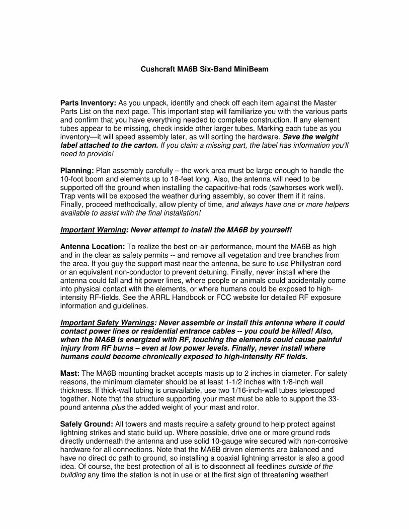
Step-1. Assemble the boom using the parts listed below: [ ] 2 Boom Tube, 1-1/2" OD x 48", slotted one end (20-MA6B-BC) [ ] 1 Boom Tube, 1-1/2" OD x 21", slotted both ends (20-MA6B-BD) [ ] 1 Boom Tube Insert, 1-3/8" OD x 48" (20-MA6B-BE) [ ] 4 Worm clamp, 1-1/4" to 1-1/2" [ ] 1 Boom-to-Mast clamping plate [ ] 2 5/16-18 x 1-5/8" x 3" U-bolt [ ] 4 5/16" split lock washer [ ] 4 5/16-18 Hex nut [ ] 2 1-1/2" Plastic end cap, for boom
Boom Assembly Stages
Boom Assembly
Boom-to-Mast Clamp Assembly
57"
Reflector End Driven Element End
60"
1-1/2" Worm Clamp (4)
1-1/2"OD x 48" 1-1/2"OD x 48"1-1/2" x 21"
1-3/8" x 48"
13-1/2" 13-1/2"
1-3/8" x 48"
1-1/2" x 21"
End cap End cap
Step-1
Step-2
Step-3
Installation Notes: Assemble boom tubes as shown above. Install end caps and secure all worm clamps tightly to prevent the boom sections from rotating out of alignment when elements are attached. Before installing the mast-to-boom clamp, measure off and mark the boom at 57" (see below):
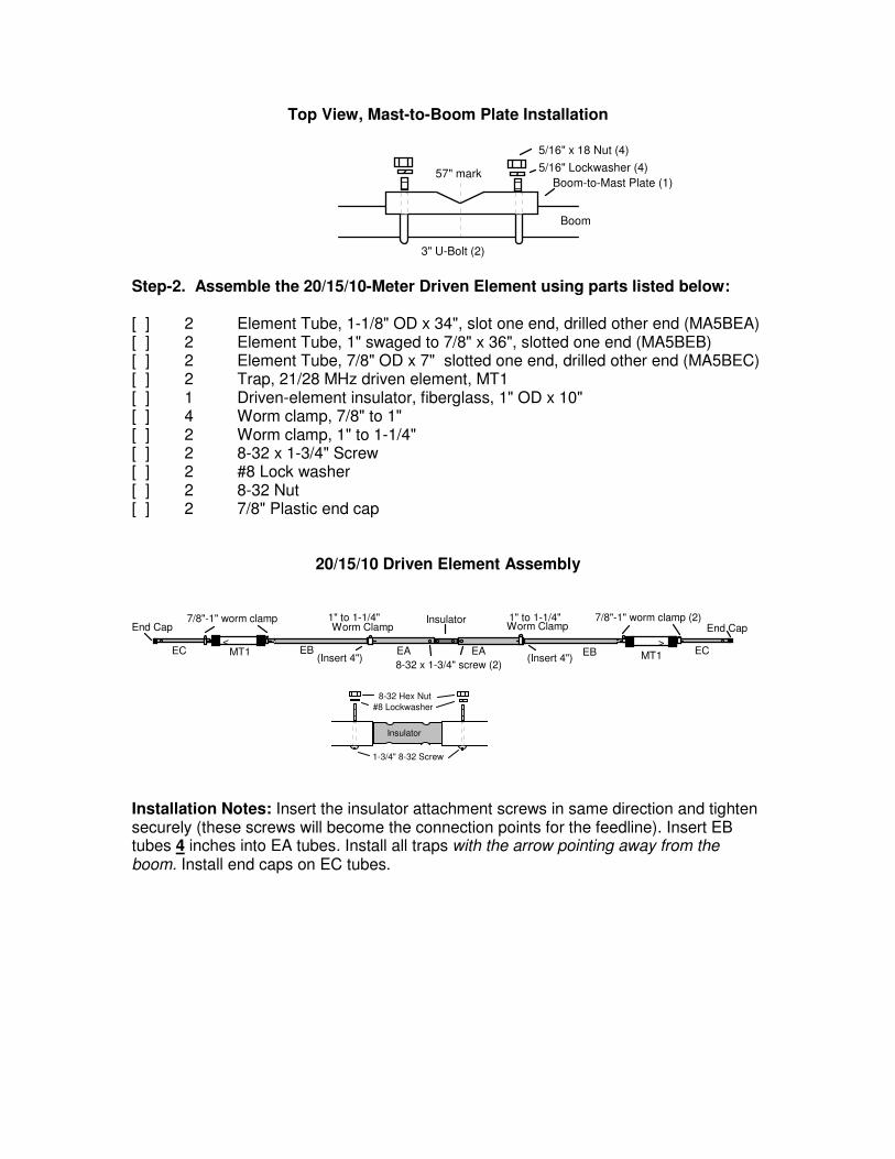
Top View, Mast-to-Boom Plate Installation
Boom
3" U-Bolt (2)
Boom-to-Mast Plate (1)
5/16" Lockwasher (4)
5/16" x 18 Nut (4)
57" mark
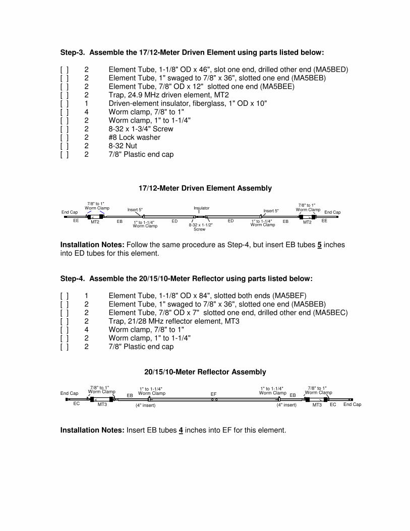
Step-2. Assemble the 20/15/10-Meter Driven Element using parts listed below: [ ] 2 Element Tube, 1-1/8" OD x 34", slot one end, drilled other end (MA5BEA) [ ] 2 Element Tube, 1" swaged to 7/8" x 36", slotted one end (MA5BEB) [ ] 2 Element Tube, 7/8" OD x 7" slotted one end, drilled other end (MA5BEC) [ ] 2 Trap, 21/28 MHz driven element, MT1 [ ] 1 Driven-element insulator, fiberglass, 1" OD x 10" [ ] 4 Worm clamp, 7/8" to 1" [ ] 2 Worm clamp, 1" to 1-1/4" [ ] 2 8-32 x 1-3/4" Screw [ ] 2 #8 Lock washer [ ] 2 8-32 Nut [ ] 2 7/8" Plastic end cap
20/15/10 Driven Element Assembly
EAEAEB EBEC ECMT1 MT1
< >
7/8"-1" worm clamp (2)End Cap
7/8"-1" worm clampEnd Cap
Insulator
8-32 x 1-3/4" screw (2)(Insert 4") (Insert 4")
1" to 1-1/4" Worm Clamp
1" to 1-1/4" Worm Clamp
1-3/4" 8-32 Screw
8-32 Hex Nut
#8 Lockwasher
Insulator
Installation Notes: Insert the insulator attachment screws in same direction and tighten securely (these screws will become the connection points for the feedline). Insert EB tubes 4 inches into EA tubes. Install all traps with the arrow pointing away from the boom. Install end caps on EC tubes.
Step-3. Assemble the 17/12-Meter Driven Element using parts listed below: [ ] 2 Element Tube, 1-1/8" OD x 46", slot one end, drilled other end (MA5BED) [ ] 2 Element Tube, 1" swaged to 7/8" x 36", slotted one end (MA5BEB) [ ] 2 Element Tube, 7/8" OD x 12" slotted one end (MA5BEE) [ ] 2 Trap, 24.9 MHz driven element, MT2 [ ] 1 Driven-element insulator, fiberglass, 1" OD x 10" [ ] 4 Worm clamp, 7/8" to 1" [ ] 2 Worm clamp, 1" to 1-1/4" [ ] 2 8-32 x 1-3/4" Screw [ ] 2 #8 Lock washer [ ] 2 8-32 Nut [ ] 2 7/8" Plastic end cap
17/12-Meter Driven Element Assembly
EE EEEBEB ED EDMT2 MT21" to 1-1/4"
7/8" to 1"
< >
End Cap
Worm Clamp
Worm ClampEnd Cap
1" to 1-1/4" Worm Clamp
7/8" to 1"Worm Clamp Insulator
8-32 x 1-1/2"Screw
Insert 5" Insert 5"
Installation Notes: Follow the same procedure as Step-4, but insert EB tubes 5 inches into ED tubes for this element. Step-4. Assemble the 20/15/10-Meter Reflector using parts listed below: [ ] 1 Element Tube, 1-1/8" OD x 84", slotted both ends (MA5BEF) [ ] 2 Element Tube, 1" swaged to 7/8" x 36", slotted one end (MA5BEB) [ ] 2 Element Tube, 7/8" OD x 7" slotted one end, drilled other end (MA5BEC) [ ] 2 Trap, 21/28 MHz reflector element, MT3 [ ] 4 Worm clamp, 7/8" to 1" [ ] 2 Worm clamp, 1" to 1-1/4" [ ] 2 7/8" Plastic end cap
20/15/10-Meter Reflector Assembly
EB EBEF
EC MT3 ECMT3< >
1" to 1-1/4"Worm Clamp
1" to 1-1/4"Worm Clamp
(4" insert) (4" insert)
7/8" to 1"Worm Clamp
7/8" to 1"Worm ClampEnd Cap
End Cap
Installation Notes: Insert EB tubes 4 inches into EF for this element.
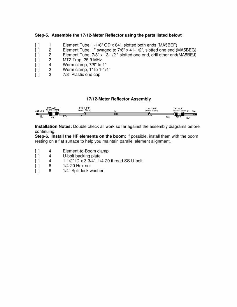
Step-5. Assemble the 17/12-Meter Reflector using the parts listed below: [ ] 1 Element Tube, 1-1/8" OD x 84", slotted both ends (MA5BEF) [ ] 2 Element Tube, 1" swaged to 7/8" x 41-1/2", slotted one end (MA5BEG) [ ] 2 Element Tube, 7/8" x 13-1/2 " slotted one end, drill other end(MA5BEJ) [ ] 2 MT2 Trap, 25.9 MHz [ ] 4 Worm clamp, 7/8" to 1" [ ] 2 Worm clamp, 1" to 1-1/4" [ ] 2 7/8" Plastic end cap
17/12-Meter Reflector Assembly
Installation Notes: Double check all work so far against the assembly diagrams before continuing. Step-6. Install the HF elements on the boom: If possible, install them with the boom resting on a flat surface to help you maintain parallel element alignment. [ ] 4 Element-to-Boom clamp [ ] 4 U-bolt backing plate [ ] 4 1-1/2" ID x 3-3/4", 1/4-20 thread SS U-bolt [ ] 8 1/4-20 Hex nut [ ] 8 1/4" Split lock washer
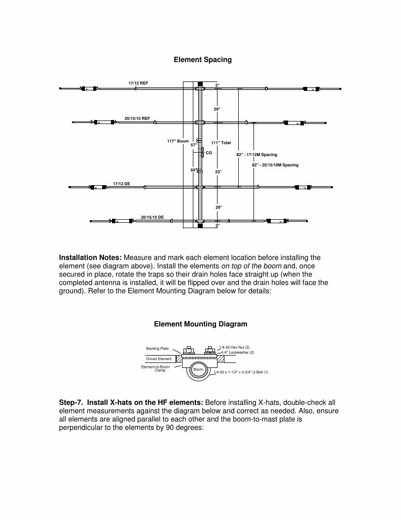
Element Spacing
<
<
<
< >
>
>
>
17/12 DE
20/15/10 DE
20/15/10 REF
29"
53"
29"
111" Total
82" - 17/12M Spacing
82" - 20/15/10M Spacing
117" Boom
3"
60"
57"
3"
CG
17/12 REF
Installation Notes: Measure and mark each element location before installing the element (see diagram above). Install the elements on top of the boom and, once secured in place, rotate the traps so their drain holes face straight up (when the completed antenna is installed, it will be flipped over and the drain holes will face the ground). Refer to the Element Mounting Diagram below for details:
Element Mounting Diagram
Driven Element
1/4-20 Hex Nut (2)
1/4" Lockwasher (2) Backing Plate
Element-to-Boom
1/4-20 x 1-1/2" x 3-3/4" U-Bolt (1)Clamp Boom
Step-7. Install X-hats on the HF elements: Before installing X-hats, double-check all element measurements against the diagram below and correct as needed. Also, ensure all elements are aligned parallel to each other and the boom-to-mast plate is perpendicular to the elements by 90 degrees:
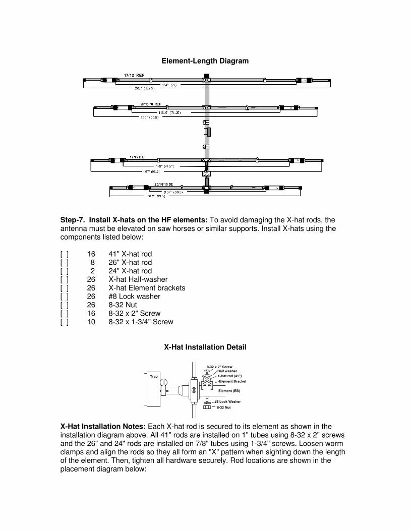
Element-Length Diagram
Step-7. Install X-hats on the HF elements: To avoid damaging the X-hat rods, the antenna must be elevated on saw horses or similar supports. Install X-hats using the components listed below: [ ] 16 41" X-hat rod [ ] 8 26" X-hat rod [ ] 2 24" X-hat rod [ ] 26 X-hat Half-washer [ ] 26 X-hat Element brackets [ ] 26 #8 Lock washer [ ] 26 8-32 Nut [ ] 16 8-32 x 2" Screw [ ] 10 8-32 x 1-3/4" Screw
X-Hat Installation Detail
8-32 x 2" ScrewHalf washer
X-Hat rod (41")
Element Bracket
Element (EB)
#8 Lock Washer
8-32 Nut
Trap
X-Hat Installation Notes: Each X-hat rod is secured to its element as shown in the installation diagram above. All 41" rods are installed on 1" tubes using 8-32 x 2" screws and the 26" and 24" rods are installed on 7/8" tubes using 1-3/4" screws. Loosen worm clamps and align the rods so they all form an "X" pattern when sighting down the length of the element. Then, tighten all hardware securely. Rod locations are shown in the placement diagram below:
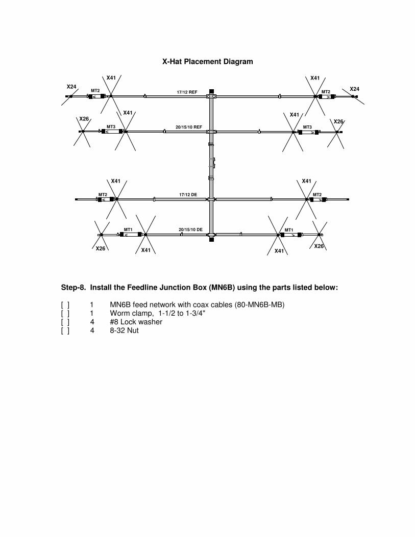
X-Hat Placement Diagram
<
<
<
< >
>
>
>
X26X26
X41
X24
X26X26
X41
X24
X41
X41 X41
X41
X41 X41
20/15/10 DE
17/12 DE
20/15/10 REF
17/12 REF
MT1 MT1
MT2 MT2
MT3 MT3
MT2 MT2
Step-8. Install the Feedline Junction Box (MN6B) using the parts listed below: [ ] 1 MN6B feed network with coax cables (80-MN6B-MB) [ ] 1 Worm clamp, 1-1/2 to 1-3/4" [ ] 4 #8 Lock washer [ ] 4 8-32 Nut
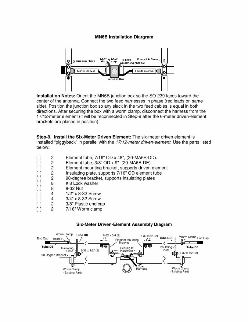
MN6B Installation Diargram
Installation Notes: Orient the MN6B junction box so the SO-239 faces toward the center of the antenna. Connect the two feed harnesses in phase (red leads on same side). Position the junction box so any slack in the two feed cables is equal in both directions. After securing the box with a worm clamp, disconnect the harness from the 17/12-meter element (it will be reconnected in Step-9 after the 6-meter driven-element brackets are placed in position). Step-9. Install the Six-Meter Driven Element: The six-meter driven element is installed “piggyback” in parallel with the 17/12-meter driven-element. Use the parts listed below: [ ] 2 Element tube, 7/16" OD x 48", (20-MA6B-DD). [ ] 2 Element tube, 3/8” OD x 9" (20-MA6B-DE). [ ] 2 Element mounting bracket, supports driven element [ ] 2 Insulating plate, supports 7/16” OD element tube [ ] 2 90-degree bracket, supports insulating plates [ ] 8 # 8 Lock washer [ ] 8 8-32 Nut [ ] 4 1/2" x 8-32 Screw [ ] 4 3/4” x 8-32 Screw [ ] 2 3/8” Plastic end cap [ ] 2 7/16" Worm clamp
Six-Meter Driven-Element Assembly Diagram
End Cap
Worm Clamp
Insulating Plate
Worm Clamp(Existing Part)
90-Degree Bracket
8-32 x 1/2" (2)
8-32 x 3/4 (2)
Existing #8Hardware
Element MountingBracket
Tube DD
HarnessCoax
Insert 4"
Tube DE
8-32 x 3/4 (2)
8-32 x 1/2" (2)
Worm Clamp End Cap
InsulatingPlate
Worm Clamp(Existing Part)
Tube DD
Tube DE
Installation Notes: Install the 6-M element-mounting brackets on the 17/12-M feed-point screws, then reinstall the coax harness on top of the bracket. Install the 90-degree element brackets onto the insulating plates with ½” screws, then loosen the worm clamps at EB/ED and secure the insulator plates as shown. To install element tube DD, insert the slotted end through the insulating plate and secure the opposite end to the mounting bracket using 3/4” screws. Then, insert end-tube DE 4 inches into DD, secure it with a worm clamp, and install the plastic end cap. Repeat the same procedure for assembling the other leg of the element. Step-10. Install the Six-Meter Reflector Element using the parts listed below: [ ] 1 Element Tube, 7/16” OD x 72", slotted ends, drilled center (20-MA6B-EG) [ ] 2 Element Tube, 3/8" OD x 28" (20-MA6B-EH) [ ] 1 Insulator Plate, ¼” x 2-1/2” x 3-1/2” [ ] 1 “L” bracket (attaches insulator plate to U-bolt assembly) [ ] 1 2-3/4” U-bolt assembly with tube clamp and ¼ – 20 hardware [ ] 2 X-hat Half-washer [ ] 2 3/8" Plastic end cap [ ] 4 #8 Lock washer [ ] 4 8-32 Nut [ ] 2 1-1/8" x 8-32 Screw [ ] 2 1/2” x 8-32 Screw [ ] 2 Worm clamp, 7/16”
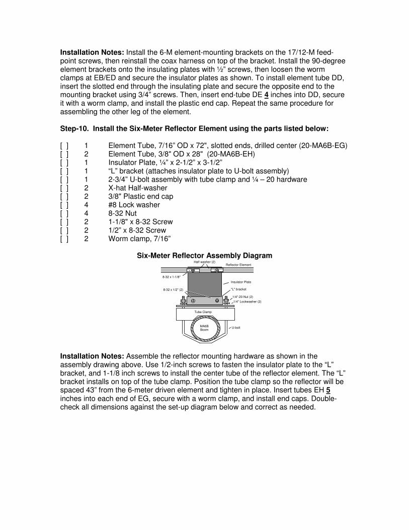
Six-Meter Reflector Assembly Diagram
1/4"-20 Nut (2)
1/4" Lockwasher (2)
Tube Clamp
Half washer (2)
BoomMA6B U-bolt
8-32 x 1/2" (2)
Reflector Element
Insulator Plate
8-32 x 1-1/8"
"L" bracket
Installation Notes: Assemble the reflector mounting hardware as shown in the assembly drawing above. Use 1/2-inch screws to fasten the insulator plate to the “L” bracket, and 1-1/8 inch screws to install the center tube of the reflector element. The “L” bracket installs on top of the tube clamp. Position the tube clamp so the reflector will be spaced 43” from the 6-meter driven element and tighten in place. Insert tubes EH 5 inches into each end of EG, secure with a worm clamp, and install end caps. Double-check all dimensions against the set-up diagram below and correct as needed.
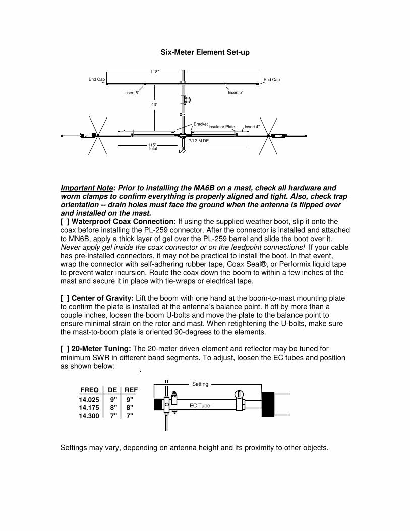
Six-Meter Element Set-up
< >
43"
17/12-M DE
Insulator PlateBracket
118"
115"total
End Cap End Cap
Insert 5" Insert 5"
Insert 4"
Important Note: Prior to installing the MA6B on a mast, check all hardware and worm clamps to confirm everything is properly aligned and tight. Also, check trap orientation -- drain holes must face the ground when the antenna is flipped over and installed on the mast. [ ] Waterproof Coax Connection: If using the supplied weather boot, slip it onto the coax before installing the PL-259 connector. After the connector is installed and attached to MN6B, apply a thick layer of gel over the PL-259 barrel and slide the boot over it. Never apply gel inside the coax connector or on the feedpoint connections! If your cable has pre-installed connectors, it may not be practical to install the boot. In that event, wrap the connector with self-adhering rubber tape, Coax Seal®, or Performix liquid tape to prevent water incursion. Route the coax down the boom to within a few inches of the mast and secure it in place with tie-wraps or electrical tape. [ ] Center of Gravity: Lift the boom with one hand at the boom-to-mast mounting plate to confirm the plate is installed at the antenna’s balance point. If off by more than a couple inches, loosen the boom U-bolts and move the plate to the balance point to ensure minimal strain on the rotor and mast. When retightening the U-bolts, make sure the mast-to-boom plate is oriented 90-degrees to the elements. [ ] 20-Meter Tuning: The 20-meter driven-element and reflector may be tuned for minimum SWR in different band segments. To adjust, loosen the EC tubes and position as shown below:
Setting
EC Tube
FREQ DE REF
14.025 9" 9"
14.175 8" 8"
14.300 7" 7"
Settings may vary, depending on antenna height and its proximity to other objects.
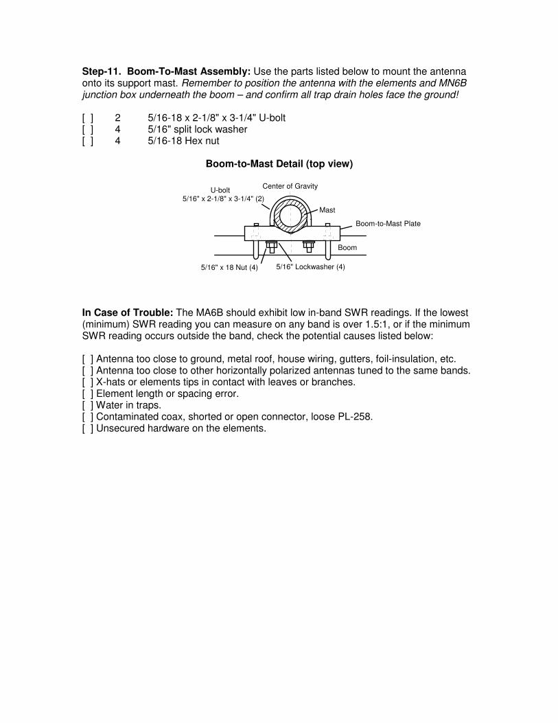
Step-11. Boom-To-Mast Assembly: Use the parts listed below to mount the antenna onto its support mast. Remember to position the antenna with the elements and MN6B junction box underneath the boom – and confirm all trap drain holes face the ground! [ ] 2 5/16-18 x 2-1/8" x 3-1/4" U-bolt [ ] 4 5/16" split lock washer [ ] 4 5/16-18 Hex nut
Boom-to-Mast Detail (top view)
Boom
Boom-to-Mast Plate
5/16" Lockwasher (4)5/16" x 18 Nut (4)
Center of Gravity
Mast
5/16" x 2-1/8" x 3-1/4" (2)U-bolt
In Case of Trouble: The MA6B should exhibit low in-band SWR readings. If the lowest (minimum) SWR reading you can measure on any band is over 1.5:1, or if the minimum SWR reading occurs outside the band, check the potential causes listed below: [ ] Antenna too close to ground, metal roof, house wiring, gutters, foil-insulation, etc. [ ] Antenna too close to other horizontally polarized antennas tuned to the same bands. [ ] X-hats or elements tips in contact with leaves or branches. [ ] Element length or spacing error. [ ] Water in traps. [ ] Contaminated coax, shorted or open connector, loose PL-258. [ ] Unsecured hardware on the elements.
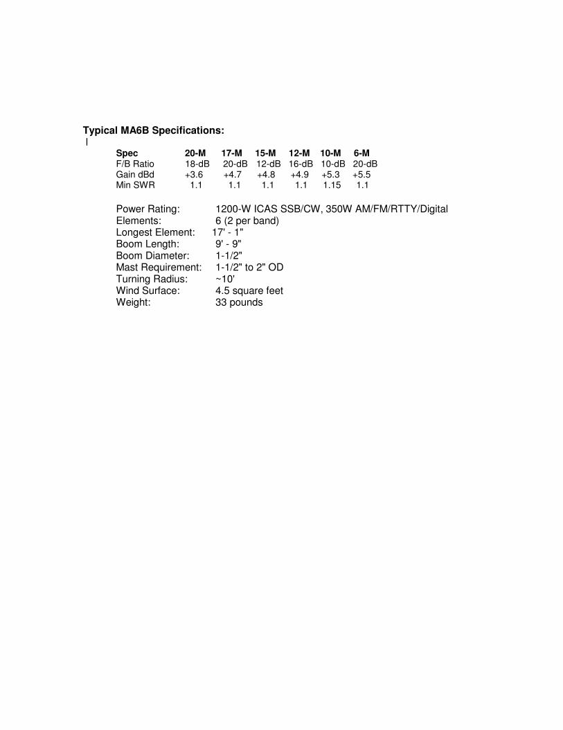
Typical MA6B Specifications: l Spec 20-M 17-M 15-M 12-M 10-M 6-M F/B Ratio 18-dB 20-dB 12-dB 16-dB 10-dB 20-dB Gain dBd +3.6 +4.7 +4.8 +4.9 +5.3 +5.5 Min SWR 1.1 1.1 1.1 1.1 1.15 1.1
Power Rating: 1200-W ICAS SSB/CW, 350W AM/FM/RTTY/Digital Elements: 6 (2 per band) Longest Element: 17' - 1" Boom Length: 9' - 9" Boom Diameter: 1-1/2" Mast Requirement: 1-1/2" to 2" OD Turning Radius: ~10' Wind Surface: 4.5 square feet Weight: 33 pounds