curved front night standcurved front night stand word... · furniture and ... the curved front...
TRANSCRIPT

Bakersfield CollegeBakersfield CollegeBakersfield CollegeBakersfield College Engineering and Engineering and Engineering and Engineering and Industrial TechnologyIndustrial TechnologyIndustrial TechnologyIndustrial Technology
Woodworking Technologies Woodworking Technologies Woodworking Technologies Woodworking Technologies Beginning Machine WoodworkingBeginning Machine WoodworkingBeginning Machine WoodworkingBeginning Machine Woodworking
Furniture and CabinetmakingFurniture and CabinetmakingFurniture and CabinetmakingFurniture and Cabinetmaking
Wood B2Wood B2Wood B2Wood B2
ProfessorProfessorProfessorProfessor: Mr. S. J. Hageman, M. A.: Mr. S. J. Hageman, M. A.: Mr. S. J. Hageman, M. A.: Mr. S. J. Hageman, M. A.
Project/Procedure BookletProject/Procedure BookletProject/Procedure BookletProject/Procedure Booklet
Curved Front Night StandCurved Front Night StandCurved Front Night StandCurved Front Night Stand
Plan borrowed with permission from:
Mr. Bob Tuttle, M.A. Bakersfield Community College
Engineering and Industrial Technology
Revisions/Additions by S. J. Hageman, M.A. Revised 12/09/09

Bakersfield College
Curved Front Night Stand
Page 2
Bakersfield College Professor: Mr. S. J. Hageman, M.A. Industrial Technology Modern Cabinetmaking; 2005 Woodworking Technologies: WEEKS 1-16 Furniture and Cabinetmaking
Project Sheet
Curved Front Night Stand
Given: Necessary equipment, materials, supplies, and all related instruction. Performance: To construct a curved front night stand from raw materials to finish product, utilizing all hand tools and machines. Standard: All measurements to be within reasonable accuracy, quality, or finish appearance to meet with the acceptance of the Instructor. Length of time should not exceed one semester or sixteen (16) weeks. Motivation [Why?]: The following pages this procedure/packet contain most of the information to construct a Curved Front Night Stand. This project has been selected for the beginning machine woodworking student because of the variety of experiences gained. Among these are: measuring, layout, joinery preparation, gluing, clamping and finishing.
It is our belief that you will receive the maximum benefit from this course by adhering to the guidelines within this packet. There will be time for short cuts and self-expression at a later date. Evaluation: The Curved Front Night Stand will be the major project for our furniture and cabinet making students. This project is required and reflects a significant percentage of your final grade.
The evaluation will be based upon: joinery, preparation, adherence to plans, over-all construction quality, bill of materials and your Daily Work Performance Evaluation. Safety: The student will complete all related Safety Instruction/demonstrations as well as all required signatures obtained prior to starting any laboratory work. Timeline: The average student will be at the following junctures during the course of the semester.

Bakersfield College
Curved Front Night Stand
Page 3
• End of Week 3: Students should have collected their rough lumber materials for the project top panel and have prepared it to receive the glue joint demonstration on the shaper. Students will then begin to rough cut materials for their project sides and back.
• End of Week 8: All project pieces should be machined to NET DIMENSIONS and rough belt
sanded by the Instructor. The student should also have rough machined all pieces for the flush drawer. Materials for the project legs should be machined to NET thickness and rough width and length. Pieces for the legs should also be rough sanded by the Instructor and ready for the demonstration relative to gluing and the use of parallel hand-screw clamps. (Note: Only if gluing up 5pcs. Of 4/4 stock.) If utilizing 8/4 lumber for the legs THEN all four (4) legs should be machined to NET dimensions and belt sanded by the Instructor.
• End of Week 10: The following pieces should be machined to NET dimensions and belt sanded by your Instructor: 1. Top panel with the curved front bandsawed, disc sanded and profile routed. 2. Two sides with ALL machining completed. 3. One back with ALL machining completed. 4. Two curved stiles with ALL machining completed. 5. One web-frame and one dust-panel with ALL machining completed. 6. Four legs with ALL machining completed. NOTE: Instructor to check student’s Bill of Materials and dimensions of the aforementioned project pieces prior to student proceeding to next steps.
• End of Week 12: Case should be finish sanded and glued together. This leaves the student with three weeks to machine and assemble the project drawer.
ROUGH CUTTING LIST

Bakersfield College
Curved Front Night Stand
Page 4
CURVED FRONT NIGHT STAND
Furniture and Cabinetmaking
PROJECT PIECES ROUGH CUTTING DIMENSIONS
NET B.F. ROUGH B.F. (Round Up)
DRAWER
ORDER _____ B.F. This Year’s Costs: /B.F. = $ ___________ Approximated Final Cost of Curved Front Night Stand:
1. Rough 4/4 Ponderosa Sugar Pine (or equivalent) @ ___ BF X ________/BF equals $_______/student.
2. Miscellaneous materials: (screws, adhesive, abrasives, buttons/plugs, oil stain, hardware, dowels, etc) $ ____
3. Facility Usage: (electrical power, wear/tear equipment, heating/cooling Maintenance/labor, insurance, etc.) equals $ ____
4. Student Labor (96 hours X $6.75/hour) equals $ ____ 5. Instructor ($240.00/day X 16 weeks / 40 students) equals $ ____
TOTAL PROJECT COST: $ ____ ACTUAL COST TO STUDENT: $
ROUGH CUTTING LIST

Bakersfield College
Curved Front Night Stand
Page 5
CURVED FRONT NIGHT STAND
Furniture and Cabinetmaking
PROJECT PIECES ROUGH CUTTING DIMENSIONS
NET B.F. ROUGH B.F. (Round Up)
DRAWER
ORDER _____ B.F. This Year’s Costs: _____/B.F. = $ ___________ Approximated Final Cost of Curved Front Night Stand:
1. Rough 4/4 Ponderosa Sugar Pine (or equivalent) @ ___ BF X ________/BF equals $_______/student.
2. Miscellaneous materials: (screws, adhesive, abrasives, buttons/plugs, oil stain, hardware, dowels, etc) $ ____
3. Facility Usage: (electrical power, wear/tear equipment, heating/cooling Maintenance/labor, insurance, etc.) equals $ ____
4. Student Labor (96 hours X $6.75/hour) equals $ ____ 5. Instructor ($240.00/day X 16 weeks / 40 students) equals $ ____
TOTAL PROJECT COST: $ ____ ACTUAL COST TO STUDENT: $
Bakersfield College Name:

Bakersfield College
Curved Front Night Stand
Page 6
Industrial Technology Semester: Fall Introduction to Furniture/Cabinetmaking Spring Professor S.J. Hageman, M.A. Week
Woodworking B2 Curved Front Night Stand
Evaluation Rubric
Note: Number values in the following rubric are represented as plus-or-minus parts of an inch. For
instance: 1/64 represents plus or minus one sixty-fourth of one inch.
Percent Earned Curved Front Night Stand All sizes are NET 100 95 90 85 80 70 60
Top: ¾ X 17-3/4 X 25-1/2 0 1/32 1/16 3/32 1/8 5/32 ¼ Sides: ¾ X 6 X 11 0 1/32 1/16 3/32 1/8 5/32 ¼ Back : ¾ X 6 X 20-1/2 0 1/32 1/16 3/32 1/8 5/32 ¼ Sub-panels: ¾ X 11-3/4 X 21-1/2 0 1/32 1/16 3/32 1/8 5/32 ¼ Legs: 1-3/4 X 1-3/4 X 29-1/4 0 1/32 1/16 3/32 1/8 5/32 ¼ Drawer Front: 7/8 X 4-7/16 X 20-3/8 0 1/32 1/16 3/32 1/8 5/32 ¼ Drawer Sides: 5/8 X 4-3/8 X 11-9/16 0 1/32 1/16 3/32 1/8 5/32 ¼ Drawer sub-front/back: 5/8 X 4-3/8 X 20-3/16
0 1/32 1/16 3/32 1/8 5/32 ¼
Fit of all joinery: including glue joints, dovetails, drawer dado/grooves, dowel, biscuit, spline, rabbet and mortise/tenon.
Accurately machined with tight
fits.
One or two very minor gaps.
Two or three very
minor gaps.
Minor gaps w/ minor
stairstep.
Minor gaps w/ several
stairsteps.
Visible gapping
and stairsteps
throughout.
Loose open fits and/or
incomplete joinery.
Accuracy of all router machined details: including top detail, side details and upper/lower sub-panel detail.
Machined as per Project Booklet.
Minor blemish in one area.
Minor blemish in one or
two areas.
Minor blemish in two or
three areas.
Minor blemish in three or
four areas.
Large and noticeable blemishes throughout
project.
Incorrect placement of details and many blemishes.
Accuracy of tapered legs: machining of leg tapers, placement on joinery onto correct faces of taper and matching of grain relative to placement of each leg.
Machined as per Project Booklet.
Incorrect placement of joinery relative to “faces” on one leg.
Incorrect placement of joinery relative to “faces” on two legs.
Incorrect machining of tapers on one or more legs.
Overall appearance/impression of the project assembly (based on the knowledge gained as a result of this course and as an informed consumer).
Mr. H would
place in his home.
Mr. H would
place in his
home.
Mr. H would
place in his home in a key location.
Mr. H would
consider placing in a key
location..
Mr. H would check
with wife RE
placement in home.
Mr. H would
place in his garage.
Mr. H would ask neighbor if interested in having project.
Project Assembly: 100 Percent Completed Incomplete: (Notate the percent completed)

Bakersfield College
Curved Front Night Stand
Page 7
Bakersfield College Name: Industrial Technology Semester: Fall Introduction to Furniture/Cabinetmaking Spring Professor S.J. Hageman, M.A. Week
Woodworking B2
Curved Front Night Stand Evaluation Rubric
Student Score: Note: Utilizing the appropriate measurement tools, accurately notate the following dimensions relative
to the required project “Curved Front Night Stand” by measuring to the nearest 1/64-inch. Two sets of measurements will be recorded. One set from the actual woodworker who manufactured the piece of furniture and the second set from a colleague in the class. Measurements in the following table will be recorded in inches.
Curved Front Night Stand Actual project
dimensions and/or observations/notes
Actual Score: 1 (Woodworker)
Actual Score: 2 (Colleague)
Top: ¾ X 17-3/4 X 25-1/2 Sides: ¾ X 6 X 11 Back : ¾ X 6 X 20-1/2 Sub-panels: ¾ X 11-3/4 X 21-1/2 Legs: 1-3/4 X 1-3/4 X 29-1/4 Drawer Front: 7/8 X 4-7/16 X 20-3/8 Drawer Sides: 5/8 X 4-3/8 X 11-9/16 Drawer sub-front/back: 5/8 X 43/8 X 20-3/16
Fit of all joinery: including glue joints, dovetails, drawer dado/grooves, dowel, biscuit, spline, rabbet and mortise/tenon.
Accuracy of all router machined details: including top detail, side details and upper/lower sub-panel detail.
Accuracy of tapered legs: machining of leg tapers, placement on joinery onto correct faces of taper and matching of grain relative to placement of each leg.
Overall appearance/impression of the project assembly (based on the knowledge gained as a result of this course and as an informed consumer).
TOTALS Evaluation No. 1 (Woodworker): Project Assembly: 100 Percent Completed Incomplete: (Notate the percent completed) Surface Finish [As achieved vis-à-vis scrapers and/or abrasive papers]: (Circle One)

Bakersfield College
Curved Front Night Stand
Page 8
100% 95% 90% 85% 75% 65% Bill of Materials: To what level of detail has the Project Bill of Materials been completed and figures calculated.
All solid lumber, masonite, hardware, adhesives, abrasive paper, biscuits, dowels, splines, finishes, etc. must be listed and accounted for in order to have a COMPLETE Bill of Materials. A total cost MUST be arrived at based on all data and listed on your Bill of Materials.
100% 95% 90% 85% 75% 65%
Observations/comments: Evaluation No. 2 (Colleague): Project Assembly: 100 Percent Completed Incomplete: (Notate the percent completed) Surface Finish [As achieved vis-à-vis scrapers and/or abrasive papers]: (Circle One)
100% 95% 90% 85% 75% 65%
Bill of Materials: To what level of detail has the Project Bill of Materials been completed and figures calculated. All solid lumber, masonite, hardware, adhesives, abrasive paper, biscuits, dowels, splines, finishes, etc. must be listed and accounted for in order to have a COMPLETE Bill of Materials. A total cost MUST be arrived at based on all data and listed on your Bill of Materials.
100% 95% 90% 85% 75% 65%
Observations/comments:
-USE BACK SIDE OF THIS PAPER FOR ADDITIONAL COMMENTS

Bakersfield College
Curved Front Night Stand
Page 9
Steps of Procedure Curved Front Night Stand
1. Sign, date, review, and demonstrate all machines and safety tests reflected in the Student
Safety Portfolio. 2. STOP … If you are wanting to “venture out” and customize your Curved Front Night Stand by
utilizing one or more species of lumber, NOW is the time to PLAN for this possibility. SEE PROFESSOR HAGEMAN … your creativity is your limit (Refer to Chapter 12: Cabinet
and Furniture Woods). This project requires the following 1/2” shank router bits:
� 3/16” Beading Bit with Bearing � 3/16” Quarter Round Bit with Bearing TJ Grinding, Inc. � 5/16” 2 Flute Carbide Straight Bit W241 S3970 Rockwood Circle � 3/8” 2 Flute Carbide Straight Bit Waukesha, WI 53189 � 1/4” X 1/4” Wing Slotted Kerf Bit with Bearing PH: 1-262-549-6885 � #137504 3/8” 4 Flute FAX: 1-262-549-7718 � Pattern Flush Trim Bit
CONSTRUCT TOP PANEL 3. Rough cut stock for Top (pgs. 316 - 319).
• Rough cut stock to length for Top (27”) • Total width of stock when laid side by side to be
approximately 22 inches • Rough cut top panel will measure
approximately 1” X 22” X 27” NOTE: Refer to Process for Squaring Lumber
on the last page of this booklet. NOTE: You will not find material that is 22”
wide. Keep in mind that the overall width of the top panel will be arrived at utilizing various widths on individual panel pieces.
4. Rough rip stock to widths of no less than 3” and no more than 6” (pgs 310 - 311).
• Insure cupped face is down when ripping or the MOST STABLE FACE DOWN. NOTE: Be advised that widths of 3-1/2” to 5-1/2” are preferred.
5. Joint one face (the most stable face) and then place an “X” on this face lightly in pencil, as per
instructor demonstration (pgs 357 – 361). 6. Surface stock to as close to 1” as possible (net thickness of all panels will be no less then
¾”), as per instructor demonstration (pgs. 362 – 364). Be certain that the face with the “X” is placed face down on the planer table for the first pass through the cutter head … then alternate faces as per instructor demonstration. a. Materials should be approximately 70% clean on both surfaces. b. Think thick!!
NOTE: Form groups of ‘X’ and surface all panels to same thickness.

Bakersfield College
Curved Front Night Stand
Page 10
7. Joint your best edge as per instructor demonstration and place an “X” on this edge lightly in pencil. Rip each board as wide as possible, removing unwanted defects. Be sure to place the “X” edge against the rip fence during this operation as per instructor demonstration (pgs. 357 – 361).
8. Arrange stock for Top panel (pgs 563 – 567).
a. Mark annular rings on end-grain as demonstrated. b. Arrange grain and knot patterns of your boards for desired effect. c. Alternate annular rings. d. Number and mark all pieces as demonstrated by Instructor
9. Machine glue joint using Shaper (pgs. 415 – 420). a. Pay particular attention to this process as demonstrated. b. Maintain stock flat to the table with a steady feed rate (use feather board as needed). c. Insure minimum stair-step (evaluate and adjust after first two edges are machined). Note: By end of day 5.
10. Using plastic resin glue (pg. 545); glue and clamp stock to form Top panel (pgs. 563 – 567). a. Using glue table and bar clamps, dry-clamp and insure good joints. b. Re-machine any flawed joint. c. Release from dry-clamping, apply plastic resin glue, re-clamp with even pressure. d. It is imperative all joints are closed, remove glue as demonstrated to inspect – ACCEPT
NO GAPS! e. Identify panel as demonstrated (name and date), store vertically. f. Leave clamped at least 12 hours. Note: By end of week 4.
11. Sand and/or scrape dried glue from all panels as per instructor demonstration. a. Remove all dried glue with 50 or 80 grit abrasive paper, utilizing a sanding block before
surfacing panels to net thickness OR utilize a glue scraper as per Instructor’s demonstration.
b. Glue scrapers can cause serious injury if used improperly. NOTE: Instructor must check all panels before next procedure. NOTE: Be sure to transfer any template measurements (and/or biscuit joints, if utilized) from
the face of all panels to the edge of each panel … once panels are surfaced to net thickness, all markings on the panel faces will be all GONE!
12. Surface panels to net thickness as per your plans and instructor demonstration [REMEMBER
to measure/check twice and cut once to avoid any disappointment (pgs. 362 – 364)] a. Maintain maximum thickness possible (no less than 3/4”). b. Consider grain and knot condition during the surfacing procedure. Make adjustments as
necessary NOTE: Once all your panels are surfaced to net thickness, transfer your edge reference markings
back onto the face of each panel so that your project templates can be redrawn. NOTE: Panels in steps 12 through 14 will be stored on your project storage shelf for some
time … soooo … you MAY want to consider surfacing these panels to net thickness at a later point so that if they do get dinged up in storage you will still be able to remove these defects. If you are careful with your storage …THEN … I would surface to net thickness at this juncture.
NOTE: BY END OF WEEK FIVE (5)

Bakersfield College
Curved Front Night Stand
Page 11
13. [Week 6] Stain knots with desired oil stain as per instructor demonstration (pgs. 732 – 738). It is the responsibility of the student to supply their own oil stain.
a. Apply and remove oil stain with a cotton rag. b. Let dry approximately 4-5 hours. THEN …
� Tape the back side of panels with masking tape. c. Fill porous knotholes and cracks with casting resin and allow to dry over-night. Note: DO NOT breathe the resin fumes or get into your eyes! d. Remove dried resin carefully with glue scraper and/or coarse grit abrasive paper
(50/60 grit).
Note: This aforementioned procedure applies to all project pieces, not ONLY your panels. Note: Instructor to rough belt sand all panels with 60/80 grit belt. Instructor to demonstrate the
sharpening and use of “HAND CABINET SCRAPER” … (Student is referred to attached article, “Scrapers: Tips for a Close Shave”).
14. [Week six (6) Demo] Machine top panel to net size as per instructor demonstration (pgs. 305 – 315). REFER TO HANDOUT “Process for Squaring Lumber.” a. Joint and mark one edge as demonstrated and place an “X” lightly in pencil on this edge. b. Rip panel to NET width. Be sure to double check that the rip fence is parallel to the
miter gauge slot in the table. THEN … Joint the ripped edge one time…NET WIDTH WILL BE 19”.
c. Square one end of all panels. d. Cut the net length and width utilizing the rip fence setup and sliding crosscut
table…NET LENGTH WILL BE 25-1/2”.
NOTE: Remember that once a set-up has been made with the table saw fence, all pieces of that dimension MUST be cut.
NOTE: Width is greater than print dimension; this is to allow extra stock for machining the curved front detail.
NOTE: Steps 1-12 and 14 by end of week five (5).
PREPARE SIDE PANELS, BACK (Week 4 NET) 1. Using machining techniques as demonstrated and learned in the construction of the top panel
prepare the following (Refer to previously mentioned textbook pages on rough cutting, jointing, ripping and crosscutting): • Two side panels to net size of 3/4” x 6” x 11”. These panels can be machined from a
single piece of stock if using pine. If using hardwood the typical maximum width of each board is 4 inches. Although considering the aesthetic value we can go to six inches here if desired, as apposed to gluing up a panel.
NOTE: The top and bottom inside edges of both SIDE PANELS will receive a 1/4” X 1/4” spline
joint in order to receive the top/bottom web frames during the assembly process. (Week 9).
• Back panel to net size of 3/4” x 6” x 20-1/2”. Again, this is net size … PLAN AHEAD!
NOTE: The top and bottom inside edges of the BACK PANEL will receive a 1/4” X 3/4” W rabbet
joint in order to receive the top/bottom web frames during the assembly process. (Week 9).
NOTE: Back and sides to NET by end of week five (5).
• Surface all stock above at same time to insure uniform thickness.

Bakersfield College
Curved Front Night Stand
Page 12
Notes:
• Correct machining process:
1. Joint one face and THEN best edge and mark both with an “X” lightly in pencil. 2. Rip to rough width if needed. 3. Surface stock to desired thickness. 4. Joint one edge and mark with an “X” lightly in pencil. 5. Rip to net width. 6. Square one end. 7. Crosscut to NET length.
• Remember to consider length restrictions of each machine. Example, the two side panels have a net length of 11 inches. This is too short to machine safely on the jointer and or planner; therefore, joint and surface one longer piece so that it is square and the correct net thickness and width. The last operation will be to cut two pieces to net length of 11 inches each.
CONTRUCT SUB-PANELS [Start Week 5 and to NET TWL” by end of week five (5)] 1. Prepare the following for construction of the sub-panels (pgs. 629-636):
• Four pieces ¾” x 2” x 11 7/8” [NET is 11 ¾”]. • Four pieces ¾” x 2” x 17 5/8”. [NET is 17 ½”] • Two pieces ¾” x 2 ¾” x 21” (Surface to NET thickness with above 8 pieces and SAVE and
LABEL; these will become your curved top/bottom sub-frame additions later in the assembly process).
• Surface all stock above at same time to insure uniform thickness. • All stock of equal width or length to be machined at same time to insure uniform dimensions. • Layout and mark stock for sub-panels as demonstrated. • Using horizontal boring machine as demonstrated prepare dowel holes. • Insert 5/16” dowels and glue up one sub-panel (use alphatic resin glue) as demonstrated, insure
sub-panel is square with no twist (pgs. 500-502). INSERT DOWELS BEFORE ROUTING KERF. Note: Use only 1-2 drops of glue when gluing END GRAIN DOWELS.
• Set up router table as demonstrated with a ¼” 3-wing slot cutter. Router table is to be setup to machine a 1/4” wide by 1/4” deep groove. “SIDE EDGES” of both web frames receive 1/4” X 1/4” spline joints and ALL four (4) inside edges of DUST PANEL receive 1/4” X 1/4” spline joint.
• Machine grooves as demonstrated to receive a dust panel. • Machine dust panel from ¼” plywood. Length and width to be 3/8” greater than inside dimensions
of sub-panel. • Glue sub-panel as before with addition of dust panel (pg. 567). • Using procedures learned previously machine sub-panels to NETSIZE (11-3/4” X 21-1/2”).
• Obtain a piece of ¼” S2S Tempered Masonite from your Instructor for your dust panel and machine to 8 7/16” W X 18 3/16” L; Square this piece of Masonite as you would with a piece of solid lumber.
NOTE: The back edge of both web panels will be “notched” to a dimension of
approximately 1/2” X 13/16” to allow for the back legs. 13/16” Note: Masonite Dust Panel Equation:
1pc. ¼” X (A + ½”) – 1/8” X (B + ½”) – 1/8” [A and B represent interior dimensions of the web frame].

Bakersfield College
Curved Front Night Stand
Page 13 3/16
Bead Detail
Mortice
3/8 wide
1/2 deep
4
1/4 X 1/4groove
1
4
CONSTRUCT LEGS (8/4 Stock to NET Dimensions Week 8/9) 1. Prepare the following for the table legs:
• 5pcs. ¾” X 4 ¼” X 31”. These pieces are “NET” rough-cut sizes. Ensure that all faces are clean. • Face glue using plastic resin glue, two groups of five of these pieces [the piece you choose as the
center of these five will end up being that portion of the leg that will be most visible – choose wisely (pg. 566)].
• After glue is dry, scrape and joint one edge, then rip each of the two 5-inch thick pieces in half with the smooth edge on the saw table (splitting the center board down its centerline).
• After splitting this leg blank, mark the two centerboard faces with a ‘X’. The ‘X’ faces will become the front face of the front legs. By marking and matching these legs they will be book-matched adding elegance to your table.
• Finish machine to generate four pieces 1-3/4” x 1-3/4” x 29-1/4” (machine stock to net thickness allowing the best face board or the “X” faces to be equal to or less than 1/8-inch thick). These faces being 18-inch thick will ensure that when we machine the taper on the leg that we will not be machining through any of our face glue joints; thus, ensuring a quality appearance. The 1/8-inch faces will become the front of the project leg and the taper will be cut from the opposite face of the glued leg board.
BACK
T = TAPER CUT FACE OF LEGS = 1/8” T SURFACED LAMINATED LEG FACE FRONT NOTE: BILL OF MATERIALS MUST BE UP-TO-DATE WITH BOTH YOUR PROJECT ROUGH AND NET DIMENSIONS.
REMEMBER THIS BILL OF MATERIALS IS PART OF THE GRADING PROCESS.
MACHINE THE MORTISE DETAILS (Week 9/10) 1. Layout and machine mortise details [(pgs. 490-496); however, we will
be utilizing the Multi-Router, NOT the Mortiser]. • Layout and machine, using the multi-router as demonstrated, the
mortise details on the legs. Two mortise details on each of the rear legs, one mortise detail on each of the front legs. Mortise detail to be centered on the width of the leg, 4” long, 3/8” wide, ½” deep and to start 1” from top end of the leg.
• Prior to this machining operation, layout and mark legs as demonstrated to ensure proper orientation and to reduce the chance of mistakes.
• Layout and machine, using the multi-router, the mortise details on the sides and back. Mortise detail to be centered on the width of the end-grain, to be 4” long, 3/8” wide, ½” deep and to start and end 1” from each edge.
STEPS for machining a sub mortise in your bases via the Multi-Router:
T
T
T
T
T
T
T
T

Bakersfield College
Curved Front Night Stand
Page 14
1. Accurately lay out your mortises. 2. Secure piece to be machined to the CL on the table with clamps. 3. Make 9/16” mark from front edge of work piece with a combination square. 4. Adjust “Depth of Cut” axis to mark in Step 2 and secure slide clamps. 5. Adjust 3/8” bit to width of mortise on your layout and secure the slide clamps. 6. Adjust the left-right lateral cutting path and secure slide clamps. 7. Plug in the Multi-Router and double check your set-up before the actual machining
process.
MACHINE THE FLOATING TENONS 1. Prepare stock for tendons.
• The instructor will surface stock to be used for tenons (3/8” thick) • Machine tenon stock to the correct width for your mortises • Using the router table, round over all four edges to 3/16 radius • Cut tenons to net length (just short of 1”) using the sliding table fixture on the table saw
MACHINE GROOVES ON SIDE PANELS AND SUB-PANELS (pgs. 484 – 487) (Week 9/10)
• Using a dado-head on the 10” table saw, machine two grooves on the inside of each side panel. Grooves to be 1/4” wide, 1/4” deep, and the full length of the side panels. Distance to be 1/4” from top and bottom edges of side panel to groove.
• Using the same saw set-up, machine grooves on the ends of both sub-panels as demonstrated.
MACHINE RABBET DETAILS ON INSIDE OF BACK (pgs. 484 – 487) (Week 9/10) • Using the dado-head on the 10” saw, set to 3/4” wide, machine a
3/4” X 1/4” deep rabbet on each inside edge of the back panel. Note: This depth might need to be adjusted to allow tight fit up of
table.
MACHINE BEAD DETAIL ON OUTSIDE BOTTOM EDGE OF SIDE PANELS (WEEK 10) • Sand surfaces of side panels as demonstrated prior to machining bead detail (pgs. 524–526). • Using router mounted in router table machine bead detail on outside bottom edge of each side
panel as demonstrated.
NOTE: Instructor to check Bill of Materials and dimensions prior to next steps.
Bakersfield College
Curved Front Night Stand
Page 15
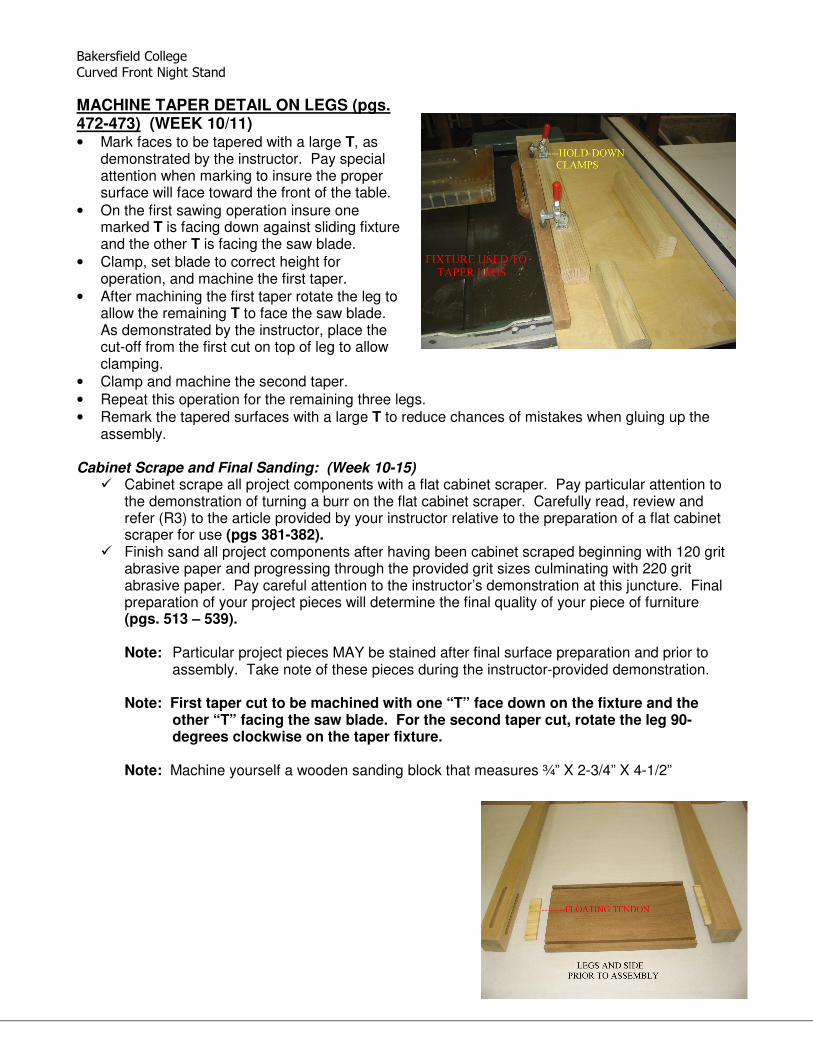
MACHINE TAPER DETAIL ON LEGS (pgs. 472-473) (WEEK 10/11) • Mark faces to be tapered with a large T, as
demonstrated by the instructor. Pay special attention when marking to insure the proper surface will face toward the front of the table.
• On the first sawing operation insure one marked T is facing down against sliding fixture and the other T is facing the saw blade.
• Clamp, set blade to correct height for operation, and machine the first taper.
• After machining the first taper rotate the leg to allow the remaining T to face the saw blade. As demonstrated by the instructor, place the cut-off from the first cut on top of leg to allow clamping.
• Clamp and machine the second taper. • Repeat this operation for the remaining three legs. • Remark the tapered surfaces with a large T to reduce chances of mistakes when gluing up the
assembly. Cabinet Scrape and Final Sanding: (Week 10-15)
� Cabinet scrape all project components with a flat cabinet scraper. Pay particular attention to the demonstration of turning a burr on the flat cabinet scraper. Carefully read, review and refer (R3) to the article provided by your instructor relative to the preparation of a flat cabinet scraper for use (pgs 381-382).
� Finish sand all project components after having been cabinet scraped beginning with 120 grit abrasive paper and progressing through the provided grit sizes culminating with 220 grit abrasive paper. Pay careful attention to the instructor’s demonstration at this juncture. Final preparation of your project pieces will determine the final quality of your piece of furniture (pgs. 513 – 539). Note: Particular project pieces MAY be stained after final surface preparation and prior to
assembly. Take note of these pieces during the instructor-provided demonstration.
Note: First taper cut to be machined with one “T” face down on the fixture and the other “T” facing the saw blade. For the second taper cut, rotate the leg 90-degrees clockwise on the taper fixture.
Note: Machine yourself a wooden sanding block that measures ¾” X 2-3/4” X 4-1/2”

Bakersfield College
Curved Front Night Stand
Page 16
GLUE-UP TWO SIDES AND LEG ASSEMBLIES (WEEK 11) • Lay out the leg and side assemblies as shown to the right. • Insure bead detail on the sides are to the outside and the bottom. • Insure the tapered faces (marked with a T) are correctly oriented. This is a very important step, if
there is any doubt verify with the instructor. • Dry clamp the assemblies to insure all parts go together correctly and to preset the clamps. • Using alphatic resin glue (yellow glue), apply glue as
demonstrated and clamp the two leg and side assemblies as illustrated to the right.
• Carefully remove all excess glue with a damp cloth. • Inspect all joints to insure soundness and make any
required adjustments. ASSEMBLE WEB FRAMES TO GLUED SIDE/LEG ASSEMBLIES (WEEK 11) • The back edges of both the sub-frame and the sub-
frame/dust panel must be laid out and then notched prior to the dry assembly process. These notches can be machined by utilizing a jig on the bandsaw, a dado head on the table saw or may be cut by hand with the use of a dovetail saw.
• One-quarter inch thick by one-half inch plywood splines must be machined in order to assemble the two sub-frames to the previously glued side assembly units. Note: Be sure that you have machined the ¼-inch by ½-inch deep spline joints on both of your
sub-frame units as well as your side panels. • After your sub-frames and accompanying splines have been machined and prepared, dry clamp
the table assembly including the back and check for fit.
ASSEMBLE CURVED TOP/BOTTOM FRONT RAILES TO SIDE/LEG ASSEMBLIES (WEEK 11) • Note: A portion of this protocol refers back to page 9 step 1 under the heading of: Construct Sub-
Panels. • Note: Ensure that you have correctly laid out and drilled at the correct angle the holes in
your top web-frame for attaching your TOP. • Locate your two (2) sub-panel pieces that were surfaced at the same time as the other sub-frame
pieces; these two (2) pieces should measure ¾” X 2-3/4” X 21”. Make certain that these pieces are of the exact thickness as your previously glued sub-frame/dust panel pieces. If they are not the same thickness see the Instructor.
• Locate and mark the centerline point of these two (2) pieces and by utilizing the same template to layout the curve for the top panel, lay out the curve on these two (2) rail pieces. Be certain to mark and match-up the center of the curve on the template and the centerline point on the rails and then lightly and accurately with a pencil trace the curve onto the rail pieces.
• Rough bandsaw the curved line on your two (2) rail pieces to within 1/16-inch to 1/8-inch outside of your pencil line. If necessary, touch up with the disc sander.
• Finish machining these two (2) rail pieces to your pencil line by utilizing the Instructor supplied router fixture to ensure uniformity.
• Measure and mark the center point between the two (2) front legs onto the rail of the top sub-frame by utilizing a combination square.

Bakersfield College
Curved Front Night Stand
Page 17
• Utilizing the combination square or framing square, match up the center line point on the sub-frame rail with the center line point of the curved rail.
• With these two points matched up, use a pencil to mark a line onto the curved rail that represents the inside edge of the front leg.
• Using the sliding table fixture, machine the curved rail to the pencil line marking. • Take the curved rail back to the dry-clamped table and mark the curved rail at the other leg like
before. When this curved rail is machined a second time to the pencil line marking it MUST fit tightly. When pressure is released from the dry clamping process, this machined curved rail will slide into place and when pressure is reapplied this machined curved rail will remain in position … THIS IS QUITE IMPORTANT FOR A QUALITY FIT AND NICE APPEARANCE.
• Layout and mark lines between the top sub-frame and the machined curved rail for biscuits. I would recommend machining three (3) number 20 biscuits.
• REPEAT THIS CURVED RAIL PROCEDURE FOR THE SECOND CURVED BOTTOM RAIL AND LABEL THEM AS UPPER AND LOWER.
• Remove assembly from the dry clamping status. • By utilizing the router table and beading bit, machine the top and bottom edges of the upper and
lower curved rails. • By utilizing the Instructor supplied fixture and router table, remove the material between the beads
on both the upper and lower curved rails. • Utilize the Instructor supplied clamping cauls, clamp the upper and lower curved rails to their
respective sub-frame units – double check to ensure that you are indeed clamping the upper curved rail to the labeled upper sub-frame unit and likewise with respect to the lower unit. Also, double check to ensure that the pencil centerline markings are facing up and that everything is in its correct order prior to the gluing/clamping process.
NOTE: Pay particular attention to the Instructor’s demonstration and whiteboard sketches
of these aforementioned steps of procedure and be sure to include them in your project booklet note section as well as in your Weekly Journal.
• The offset between the end-grain end of the curved rails and the face of its accompanying leg
should be visually the same to ensure balance and harmony. • Dry clamp the table assembly to ensure a quality fit and to determine a successful clamping
arrangement. You DO NOT want to discover half way through the gluing/clamping process that you did not have a good plan of attack. It is worth the extra think time now to save you time and heartache later.
• When you are happy with your quality of fit, then layout your gluing and clamping tools and materials, get a colleague to help and go ahead and glue and reassemble your case unit.
• REFER TO THE DRAWER SECTION OF THIS PROJECT BOOKLET AND MAKE YOUR DRAWER AS PER THE SPECIFICATIONS AND GUIDELINES.
Note: Once your drawer parts are machined and assembled per the guidelines and
demonstrations, be sure to install the completed drawer into your case unit and be content with its operation BEFORE fitting the to the case.
ASSEMBLE TOP TO CASE UNIT (WEEK 11/12) • Layout and pre-drill your 3/16-inch clearance holes at an angle into your upper sub-frame. You
must consider the angle of the screwdriver when attaching the top. Clearance holes drilled at the correct angle will help to ensure an easier assembly of the top to the sub-frame. Remember that there is a dust panel in the bottom drawer-frame that will restrict your screwdriver.

Bakersfield College
Curved Front Night Stand
Page 18
• Place a protective padding onto the workbench surface and then lay your top with the good face down onto this padding.
• Measure, layout and mark that your case unit is centered onto your top ensuring an equidistant offset to the legs.
• If you utilized a “soft wood” for your project, then the screw can be installed without any pre-drilling; however, if you utilized a “hard wood,” then mark through your pre-drilled clearance holes in the top sub-frame onto the face of the top panel and pre-drill these 1/8 inch pilot holes. Be careful to duplicate the angle from the pre-drilled holes in your sub-frame and that you DO NOT drill completely through your top panel.
• The screw heads must be flush with or below the surface of the sub-frame so as not to interfere with the operation of your drawer. Therefore, these clearance holes in your sub-frame must be counter sunk.
MACHINE STOCK FOR DRAWERS (WEEK 13/15) 1. Machine stock for the drawer sides. REMEMBER TO ROUGH CUT PRIOR TO MACHINING
TO NET SIZES.
• One piece 1 3/4” X 4 7/16” X 20 13/32” Drawer front NET; utilize 8/4 stock as per NOTE: W = 1/16” less than opening. Instructor demonstration. L= 3/32”less than opening.
• Two pieces ½” x 4 3/8 “ x 20 3/16” Drawer back and sub front NET • Two pieces ½ “ x 4 3/8” x 11 9/16” Drawer sides NET • One piece ¼” x 13” X 24” Drawer bottom ROUGH
Note: Utilizing the portable electric router and table, run an edge detail along the top edges of
both drawer sides prior to the assembly process as per instructor demonstration. Note: To achieve added quality to your drawer unit, ask Mr. Hageman to discuss with you the
procedure for manufacturing an “upper drawer kicker.” This will keep your drawer from sagging when fully extended.
2. Proceed as shown in demonstration with either hand-cut or machined dovetail joints. 3. Follow demonstration procedures for assembly and installation of drawer unit.
Note: The student MAY want to consider utilizing a different species of wood for the interior drawer pieces … time permitting. Talk to your instructor regarding the “tricking out” of your drawer unit. This may include inlays, carvings, secret compartments, et.al.
Note: Refer to CHAPTER 42, pgs. 667 – 680 in your textbook, Modern Cabinetmaking,
by Umstadt and Davis.
Bakersfield College
Curved Front Night Stand
Page 19
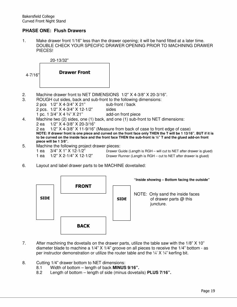
PHASE ONE: Flush Drawers 1. Make drawer front 1/16” less than the drawer opening; it will be hand fitted at a later time.
DOUBLE CHECK YOUR SPECIFIC DRAWER OPENING PRIOR TO MACHINING DRAWER PIECES!
20-13/32” 4-7/16” 2. Machine drawer front to NET DIMENSIONS 1/2” X 4-3/8” X 20-3/16”. 3. ROUGH cut sides, back and sub-front to the following dimensions: 2 pcs 1/2” X 4-3/4” X 21” sub-front / back 2 pcs. 1/2” X 4-3/4” X 12-1/2” sides 1 pc. 1 3/4” X 4 ¾” X 21” add-on front piece 4. Machine two (2) sides, one (1) back, and one (1) sub-front to NET dimensions: 2 ea 1/2” X 4-3/8” X 20-3/16” 2 ea 1/2” X 4-3/8” X 11-9/16” (Measure from back of case to front edge of case) NOTE: If drawer front is one piece and curved on the front face only THEN the T will be 1 13/16”. BUT if it is
to be curved on the inside face and the front face THEN the sub-front is ½” T and the glued add-on front piece will be 1 3/8”.
5. Machine the following project drawer pieces: 1 ea 3/4” X 1” X 12-1/2” Drawer Guide (Length is RGH – will cut to NET after drawer is glued)
1 ea 1/2” X 2-1/4” X 12-1/2” Drawer Runner (Length is RGH – cut to NET after drawer is glued)
6. Layout and label drawer parts to be MACHINE dovetailed: “Inside showing – Bottom facing the outside”
NOTE: Only sand the inside faces of drawer parts @ this juncture. 7. After machining the dovetails on the drawer parts, utilize the table saw with the 1/8” X 10”
diameter blade to machine a 1/4” X 1/4” groove on all pieces to receive the 1/4” bottom - as per instructor demonstration or utilize the router table and the ¼’ X ¼” kerfing bit.
8. Cutting 1/4” drawer bottom to NET dimensions:
8.1 Width of bottom – length of back MINUS 9/16”. 8.2 Length of bottom – length of side (minus dovetails) PLUS 7/16”.
Drawer Front
FRONT
BACK
SIDE
SIDE
Bakersfield College
Curved Front Night Stand
Page 20
PROCESS FOR SQUARING LUMBER: 1. Joint the concave face to 70% clean. 2. Surface to rough thickness – 70% clean. 3. Joint the best edge to 100% clean. 4. Rip to width to get rid of any defects. 5. Joint the ripped edge one time. 6. Prep panels for gluing. NOTE: Check each machining for square / 90°. 7. Square one end. 8. Cut to net length.
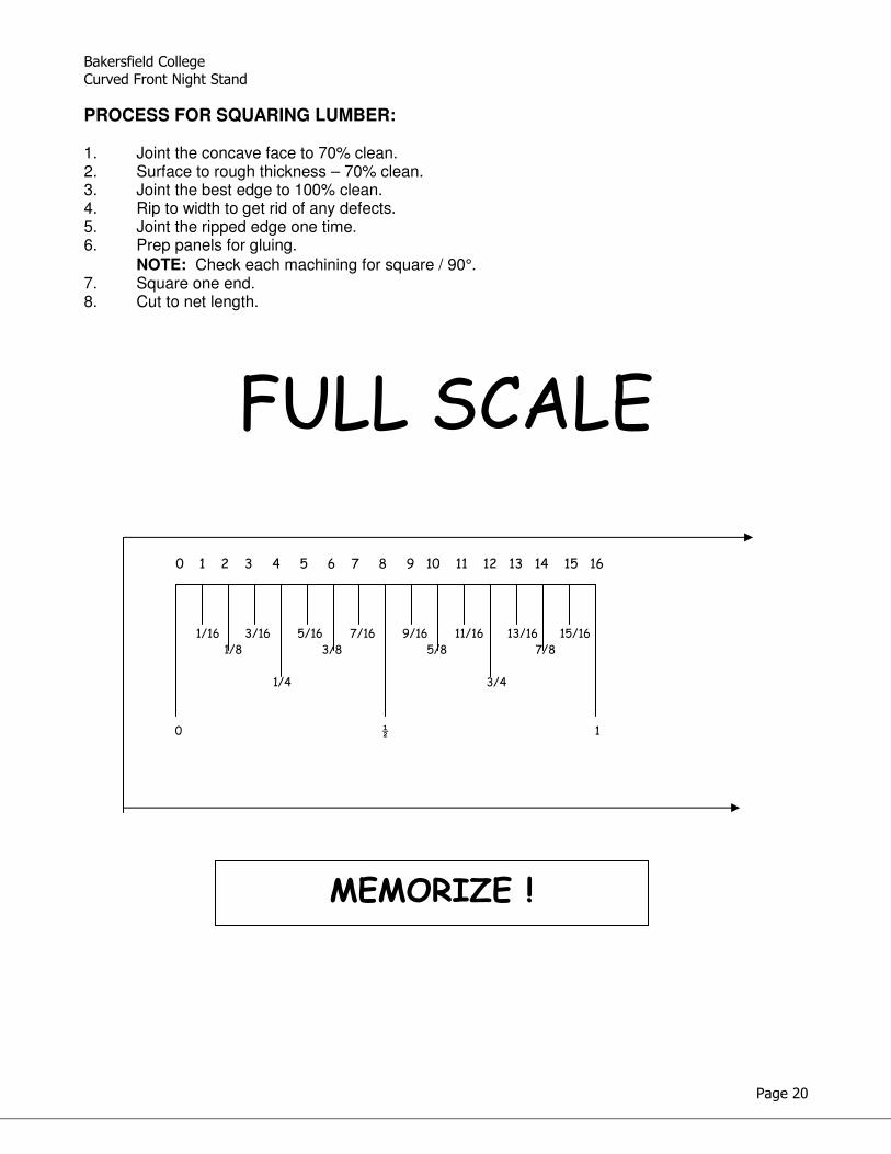
FULL SCALE
0 1 2 3 4 5 6 7 8 9 10 11 12 13 14 15 16
1/16 3/16 5/16 7/16 9/16 11/16 13/16 15/16
1/8 3/8 5/8 7/8
1/4 3/4
0 ½ 1
MEMORIZE !

Bakersfield College
Curved Front Night Stand
Page 21
NOTES

Bakersfield College
Curved Front Night Stand
Page 22
NOTES

Bakersfield College
Curved Front Night Stand
Page 23
NOTES

Bakersfield College
Curved Front Night Stand
Page 24
NOTES

Bakersfield College
Curved Front Night Stand
Page 25
BAKERSFIELD COLLEGE INSTRUCTOR: MR. S. J. HAGEMAN INDUSTRIAL TECHNOLOGY WOODWORKING TECHNOLOGY DRAW\WOOD2\curvedfrontdraw
BEGINNING MACHINE WOODWORKING – WOOD 2
SUB FRAMESTWO EACH (ONE WITH 1/4" DUST PANEL)
FRAME PIECES ROUGH 2" WIDE
CURVED EDGING - TWO EACH
SIDE PANELS (2) 11 x 6
BACK PANEL - 20 1/2 x 6
Top
ROUGH SIZE 26 1/2 x 19
LEGS (4) 1 3/4 x 1 3/4 x 29.25 (LENGH MAY BE CHANGED TO
MEET REQUIREMENTS) - TWO
FACES TAPER TO 7/8
DRAWER