curve let
TRANSCRIPT

7/27/2019 Curve Let
http://slidepdf.com/reader/full/curve-let 1/13
J. Basic. Appl. Sci. Res., 2(11)11296-11308, 2012
© 2012, TextRoad Publication
ISSN 2090-4304
Journal of Basic and Applied
Scientific Research www.textroad.com
*Corresponding Author: Mahsa Bazargani, Islamic Azad University-Qeshm branch Qeshm, IranEmail: [email protected]
Digital Image Watermarking in Wavelet, Contourlet and Curvelet Domains
Mahsa Bazargani1, Heidar Ebrahimi
2, Reza Dianat
3
1Islamic Azad University- Qeshm branch, Iran2Shahid chamran university of ahvaz,Iran
3Persian Gulf University,Boushehr.Iran
ABSTRACT
In this paper a digital image watermarking algorithm in Wavelet, Contourlet and Curvelet transform domains is
proposed. In the algorithm original gray image is decomposed into coefficients in different sub-bands. For selected
subband in each domain the watermark is embedded in the father nodes by relationship between father node and
the maximum or minimum value of its child node. The experimental results show that the algorithm is invisible and
robust against common image processing and attacks. Moreover it outperforms previous methods in the most
situations.
Keywords: wavelet, contourlet , curvelet, watermark, father node, child nodes
1. INTRODUCTION
Nowadays computer networks and multimedia technologies are omnipresent and the transfer of electronicdocuments via these networks becomes inevitable. Digital watermarking is an effective copyright protection method.
In a watermarking system the primary goal is to achieve a high level of robustness. Generally digital image
watermarking has certain requirements, the most important being robustness and invisibility. Some information thatthe embedded watermarks like (Signature, Logo, ID number, etc) cannot be removed by attacks. The watermarking
techniques are broadly categorized in tow groups, the spatial domain and frequency domain [1,2,3]. One of the best
way to transform in watermarking techniques is Discrete Wavelet Transform (DWT). But this technique do not
possess the directional information such as directional edges of image. Contourlet Transform (CT) and Fast Discrete
Coverlet Transform (FDCT) capable of capturing the directional information with multiresolution representation. In
this paper a blind digital watermarking algorithm based on wavelet , contourlet and curvelet transform is proposed
and compared together. The rest of paper is organized as follows: In section2, about DWT, CT and FDCT arediscussed. The image watermark embedding and extraction algorithm is given in section 3. Experimental results are
presented in section 4. Section 5 draws conclusions.
2. DWT, CT and FDCT
2.1. Discrete Wavelet TransformAmongst watermarking methods, Discrete Wavelet Transform (DWT) based ones are the most popular
techniques. Using multiresolution decomposition methods, at first, the host image is transformed into several
subbands. Then for concealing the watermark information in the host image, its bits are embedded into some
selected subbands. In this embedding two facts must be considered: (i) Changing the wavelet coefficients in high
frequency subbands somewhat results in image edge distortion; and the watermarking in these subbands has not a
reliable robustness face to attacks (ii) Altering the wavelet coefficients in low frequency subbands significantly leads
to image distortion since a high proportion of image information located in low frequency subbands [4]; The DWT
is a powerful and a popular transform, which is familiar to image processing community. In two- dimensionalapplications, a given image is decomposed by DWT into four sub-bands (i.e. LL1, HL1, LH1, and HH1). The sub-
band (LL1) is representative of the low frequency part where most energy is concentrated, while the other sub-bands
display the high frequency content in the horizontal, vertical and diagonal directions. The sub-band (LL1) is further decomposed into other four sub-bands in order to obtain the next wavelet level. The required decomposition level is
reached by the repetition of this process for several times[5,6]. An example of three-level wavelet decomposition
sub-bands is shown in Figure 1[6].
11296
7/27/2019 Curve Let
http://slidepdf.com/reader/full/curve-let 2/13
Bazargani et al., 2012
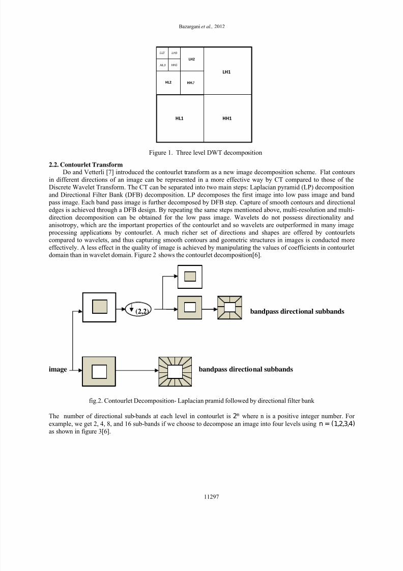
Figure 1. Three level DWT decomposition
2.2. Contourlet TransformDo and Vetterli [7] introduced the contourlet transform as a new image decomposition scheme. Flat contours
in different directions of an image can be represented in a more effective way by CT compared to those of the
Discrete Wavelet Transform. The CT can be separated into two main steps: Laplacian pyramid (LP) decomposition
and Directional Filter Bank (DFB) decomposition. LP decomposes the first image into low pass image and band
pass image. Each band pass image is further decomposed by DFB step. Capture of smooth contours and directionaledges is achieved through a DFB design. By repeating the same steps mentioned above, multi-resolution and multi-
direction decomposition can be obtained for the low pass image. Wavelets do not possess directionality and
anisotropy, which are the important properties of the contourlet and so wavelets are outperformed in many image
processing applications by contourlet. A much richer set of directions and shapes are offered by contourletscompared to wavelets, and thus capturing smooth contours and geometric structures in images is conducted more
effectively. A less effect in the quality of image is achieved by manipulating the values of coefficients in contourletdomain than in wavelet domain. Figure 2 shows the contourlet decomposition[6].
.....
(2,2) bandpass directional subbands
image bandpass directional subbands
fig.2. Contourlet Decomposition- Laplacian pramid followed by directional filter bank
The number of directional sub-bands at each level in contourlet is 2 where n is a positive integer number. For
example, we get 2, 4, 8, and 16 sub-bands if we choose to decompose an image into four levels using n = (1,2,3,4)
as shown in figure 3[6].
HL1
LH1
HH1
HL2
LH2
HH2
HH3
LH3 LL3
HL3
11297

7/27/2019 Curve Let
http://slidepdf.com/reader/full/curve-let 3/13
J. Basic. Appl. Sci. Res., 2(11)11296-11308, 2012
Low pass band
Level 4
Level 3
Level 2
Level 1
Fig.3. Contourlet Decomposition
2.3Fast Discrete Curvelet TransformIn recent years, curvelet have been redesigned with a new mathematical architecture, which is simpler and easy
to be implemented. It is known as Fast Discrete Curvelet Transform which is proposed by Candµes and Donoho[8,9]. They suggested two new strategies, namely Unequi-Spaced Fast Fourier Transform (USFFT) and
Frequency wrapping. The Wrapping based Curvelet transform techniques was found to be conceptually simpler,
computed faster and less redundant than the previous techniques. Therefore, it is common to be used in researchesimplementing the curvelet transform. In this paper we focus on the wrapping DCT method.
Wrapping DCT Algorithm[10]:
1. Take FFT of the image
2. Divide FFT into collection of Digital Corona Tiles (Figure.4.a)
3. For each corona tile
(a) Translate the tile to the origin (Figure.4.b)
(b) Wrap the parallelogram shaped support of the tile around a rectangle centered at the origin (Figure.4.c)(c) Take the Inverse FFT of the wrapped support(d) Add the curvelet array to the collection of curvelet coefficients.
11298
7/27/2019 Curve Let
http://slidepdf.com/reader/full/curve-let 4/13
Bazargani et al., 2012
Fig4.(a) Fig4.(b) Fig4.(c)
3. Watermarking Algorithm
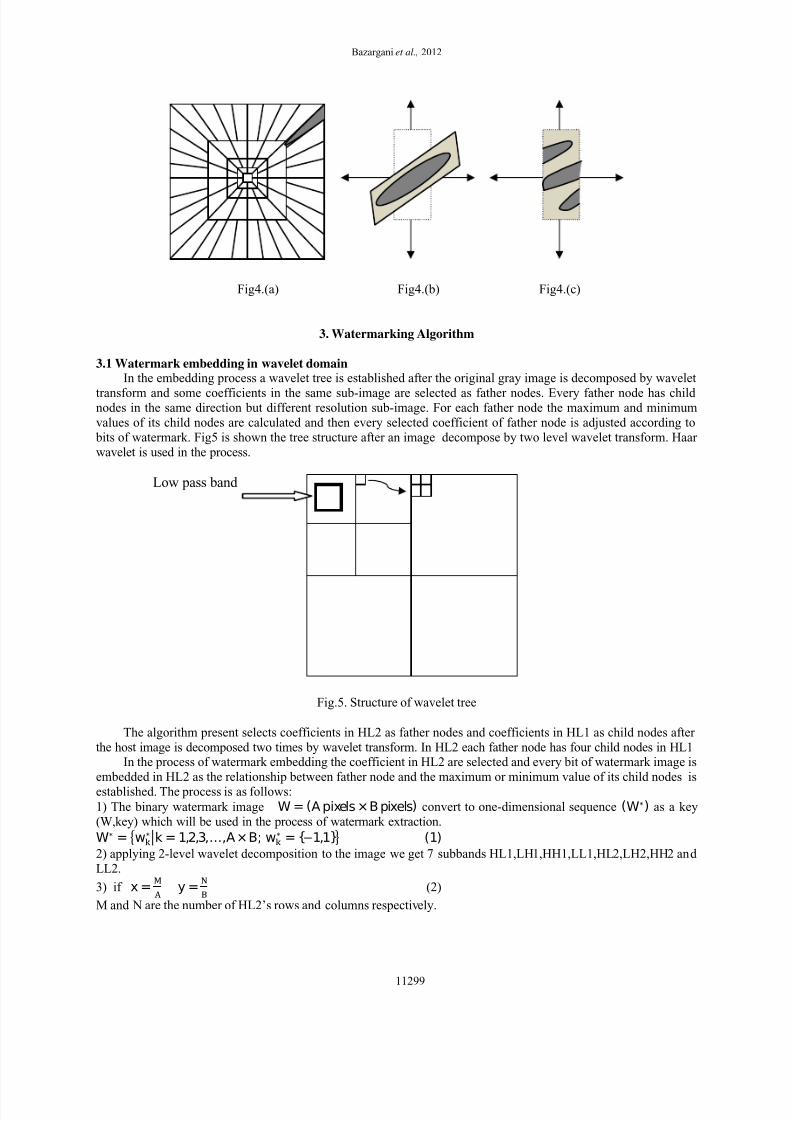
3.1 Watermark embedding in wavelet domainIn the embedding process a wavelet tree is established after the original gray image is decomposed by wavelet
transform and some coefficients in the same sub-image are selected as father nodes. Every father node has child nodes in the same direction but different resolution sub-image. For each father node the maximum and minimum
values of its child nodes are calculated and then every selected coefficient of father node is adjusted according to
bits of watermark. Fig5 is shown the tree structure after an image decompose by two level wavelet transform. Haar
wavelet is used in the process.
Low pass band
Fig.5. Structure of wavelet tree
The algorithm present selects coefficients in HL2 as father nodes and coefficients in HL1 as child nodes after
the host image is decomposed two times by wavelet transform. In HL2 each father node has four child nodes in HL1In the process of watermark embedding the coefficient in HL2 are selected and every bit of watermark image is
embedded in HL2 as the relationship between father node and the maximum or minimum value of its child nodes is
established. The process is as follows:
1) The binary watermark image W = (Apixels ×Bpixels) convert to one-dimensional sequence (W∗) as a key
(W,key) which will be used in the process of watermark extraction.
W∗ = w∗k = 1,2,3,…,A ×B;w∗ = {−1,1}(1)
2) applying 2-level wavelet decomposition to the image we get 7 subbands HL1,LH1,HH1,LL1,HL2,LH2,HH2 and
LL2.
3) if x = y =
(2)
M and N are the number of HL2’s rows and columns respectively.
11299
7/27/2019 Curve Let
http://slidepdf.com/reader/full/curve-let 5/13
J. Basic. Appl. Sci. Res., 2(11)11296-11308, 2012
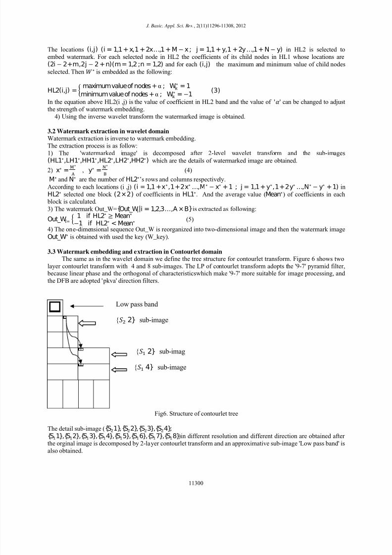
The locations (i,j)(i = 1,1 + x,1 + 2x…,1 + M− x; j = 1,1 + y,1 +2y…,1 + N− y) in HL2 is selected to
embed watermark. For each selected node in HL2 the coefficients of its child nodes in HL1 whose locations are(2i − 2+m,2j − 2 + n)(m = 1,2;n = 1,2) and for each (i,j) the maximum and minimum value of child nodes
selected. Then ∗is embedded as the following:
HL2(i,j) =
maximumvalueof nodes + α;W∗ = 1
minimumvalueof nodes +α;W∗ = −1(3)
In the equation above HL2(i ,j) is the value of coefficient in HL2 band and the value of '' can be changed to adjust
the strength of watermark embedding.
4) Using the inverse wavelet transform the watermarked image is obtained.
3.2 Watermark extraction in wavelet domainWatermark extraction is inverse to watermark embedding.
The extraction process is as follow:
1) The 'watermarked image' is decomposed after 2-level wavelet transform and the sub-images(HL1∗,LH1∗,HH1∗,HL2∗,LH2∗,HH2∗) which are the details of watermarked image are obtained.
2) x∗ =∗ , y∗ =
∗ (4)
M∗and N∗ are the number of HL2∗’s rows and columns respectively.
According to each locations (i ,j) (i = 1,1 +x∗,1+2x∗ …,M∗ − x∗ + 1; j = 1,1+ y∗,1+2y∗ …,N∗ − y∗ +1) in
HL2∗ selected one block (2×2) of coefficients in HL1∗. And the average value (Mean∗) of coefficients in each block is calculated.
3) The watermark Out_W={Out_W|i = 1,2,3…,A ×B}is extracted as following:
Out_W 1if HL2∗ ≥ Mean∗−1if HL2∗ < Mean∗ (5)
4) The one-dimensional sequence Out_W is reorganized into two-dimensional image and then the watermark image
Out_W∗ is obtained with used the key (W_key).
3.3 Watermark embedding and extraction in Contourlet domainThe same as in the wavelet domain we define the tree structure for contourlet transform. Figure 6 shows two
layer contourlet transform with 4 and 8 sub-images. The LP of contourlet transform adopts the '9-7' pyramid filter, because linear phase and the orthogonal of characteristicswhich make '9-7' more suitable for image processing, and
the DFB are adopted 'pkva' direction filters.
Low pass band
{2} sub-image
{2} sub-imag
{4} sub-image
Fig6. Structure of contourlet tree
The detail sub-image ({S1},{S2},{S3},{S4}; {S1},{S2},{S3},{S4},{S5},{S6},{S7},{S8})in different resolution and different direction are obtained after
the orginal image is decomposed by 2-layer contourlet transform and an approximative sub-image 'Low pass band' is
also obtained.
11300

7/27/2019 Curve Let
http://slidepdf.com/reader/full/curve-let 6/13
Bazargani et al., 2012
The S2 is selected to embed watermark as father node and For each selected node in S2 the coefficients of its child
nodes in S2 and S4 whose locations are (i,2j − 2 + n)(n = 1,2) selected.
Then all of the steps are same embedding algorithm in wavelet domain and for extraction watermark for each
locations (i,j) in S∗2 selected one block (1×2) of coefficients in S∗2 and one block (1×2) of coefficients in S∗4and the other steps is the same extraction algorithm in wavelet domain.
3.4 Watermark embedding and extraction in Curvelet domainWhen we used CurveLab 2.0 software package [11] output define as cells. The decomposition subbands by
wrapping curvelet transform with 4 scales and 8 angles As the following:
{1×1}: Low pass band
{1 ×8}:,,,,,,,
{1 ×16}:,,,,,,,,,,,,,,,
{1 ×16}:,,,,,,,,,,,,,,,
For the binary watermark image W = (Apixels ×Bpixels) in the process of watermark embedding the coefficient
in S are selected as father node.
if x = y =
(6)
M is the number of S’s row.
The location (i,j
)
(i = 1,1+ x,1 +2x…,M− x+ 1; j = 1,1 +y,1 +2y…,M − y +1)in
is selected to
embed watermark. For each selected node in the coefficients of its child nodes in whose locations are(2i − 2+m,2j − 2 + n)(m = 1,2;n = 1,2) and for each (i,j) the maximum and minimum value of child nodes
selected. Then the other steps are same the embedding and extraction in wavelet doman.
4. EXPERIMENTAL RESULTS
The standard (512×512) gray-level wpeppers image is used as the host image. The watermark image (Logo) is
a binary image with the size (16×32) pixels. Fig 7(a) is shown the host image and the watermark image in fig 7(b).
the value of α in wavelet domain is (20) and in contourlet domain is (33) and in curvelet domain is (160). The
image containing watermark using wavelet transform and the extracted watermark Out_W∗ is shown in fig 7(c) and
7(d) respectively. The image containing watermark using contourlet transform and the extracted watermark Out_W∗ is shown in fig 7(e) and 7(f) respectively. The image containing watermark using curvelet transform and the
extracted watermark Out_W∗ is shown in fig 7(g) and 7(h) respectively.
PSNR (Peak signal to noise ratio) is used to measure the invisibility of the embedded watermark in cover
image and NC(normalized cross-correlation) is used to measure the similarity between the extracted watermark and
the original watermark. PSNR and NC are given by:
The size of host image "h" is (M×N)
The watermarked image is h∗ MSE=
×∑ ∑ |h(i,j) − h∗(i,j)| (7)
PSNR=20 log(
√ ) (8)
NC=∑∑. _ ∗
∑∑ ∑∑ _ ∗ (9)
(a) (b) (c) (d)
11301

7/27/2019 Curve Let
http://slidepdf.com/reader/full/curve-let 7/13
J. Basic. Appl. Sci. Res., 2(11)11296-11308, 2012
(e) (f) (g) (h)
Fig7.(a)gray image, (b)watermark image, (c)watermarked image using wavelet transform with PSNR=46.49,
(d)extracted watermark with NC=1,(e)watermarked image using contourlet transform with PSNR=44.60,
(f)extracted watermark with NC=1,(g)watermarked image using curvelet transform with PSNR=39.85, (h)extracted
watermark with NC=1.
Figure 8,9 and 10 show the PSNR and NC versus in wavelet, contourlet and curvelet respectively.
The comparison PSNR and NC versus Quality Factor compression are shown in figure 11and 12 respectively. The
experimental results of attacks on the watermarked image lena, wpeppers and wflower in wavelet transform domain
is shown in table1 and compareing the proposed method in wavelet transform domain with Wang[12], Li[13],
Lin[14] and [15]by Lena (512×512) gray image and watermark(16×32) using wavelet transform is shown in table2
and comparing the watermark extracted (16×32) in proposed method in wavelet, contourlet and curvelet transform
domain by Lena (512×512) gray image is shown in table3 and comparing the proposed method in wavelet,
contourlet and curvelet transform domain by Lena (512×512) gray image and watermark(16×32) is shown in table4.
The compareing the proposed method in contourlet transform domain with Zhu[16] by Lena(512×512) gray imageand watermark(32×32) is shown in table5 and watermark extracted(32×32) in contourlet transform domain byLena(512×512) gray image is shown in table6.
The compareing the proposed method in curvelet transform domain with Zhang[17] and Thai[18] by
Lena(512×512) gray image and watermark(16×16) is shown in table7 and watermark extracted(16×16) in curvelet
transform domain by Lena(512×512) gray image is shown in table8.
Fig8.(a) Fig8.(b)
Fig8.(a) PSNR versus in wavelet domain. Fig8.(b) NC versus in wavelet domain
Fig9.(a) Fig9.(b)
Fig9.(a) PSNR versus
in contourlet domain. Fig9.(b) NC versus
in contourlet domain
Fig10.(a) Fig10.(b)
Fig10.(a) PSNR versus in cuuveletdomain. Fig10.(b) NC versus in curvelet domain
0 5 10 15 20 2542
44
46
48
50
52
54
alpha
P S N R
0 5 10 15 20 250.992
0.993
0.994
0.995
0.996
0.997
0.998
0.999
1
.
alpha
N C
5 10 15 20 25 30 35 4042
44
46
48
50
52
54
alpha
P S N R
5 10 15 20 25 30 35 400.992
0.993
0.994
0.995
0.996
0.997
0.998
0.999
1
1.001
alpha
N C
80 90 100 110 120 130 140 150 160 170 18038
39
40
41
42
43
44
45
46
alpha
P S N R
80 90 100 110 120 130 140 150 160 170 1800.975
0.98
0.985
0.99
0.995
1
1.005
alpha
N C
11302

7/27/2019 Curve Let
http://slidepdf.com/reader/full/curve-let 8/13
Bazargani et al., 2012
Fig11. PSNR versus Quality Factor Compression
Fig12. NC versus Quality Factor Compression
Table.1. The compareing (NC) in wavelet transform domain for Lena, wpeppers and wflower gray imagesJPEG compression QF 10 20
NC/Lena0.300.60
NC/wpeppers0.280.34
NC/wflower 0.300.40
JPEG compression QF 3040
NC/Lena0.800.98
NC/wpeppers 0.750.98
NC/wflower 0.75 0.99
JPEG compression QF 50 60
NC/Lena0.991
NC/wpeppers11
NC/wflower 11
JPEG compression QF 7090 NC/Lena11
NC/wpeppers11
NC/wflower 11
Attack Rotate
0.25° 0.25°-
NC/Lena0.700.77
NC/wpeppers0.650.85
NC/wflower 0.600.80
Attacks Cropping (1/4) Resize (Scale=0.5)
NC/Lena 0.800.94
NC/wpeppers 0.820.96
NC/wflower 0.820.95
Attack Average filtering
[5×5] [3×3]
NC/Lena 0.400.91 NC/wpeppers 0.550.96
NC/wflower 0.33 0.94
Attack Salt and pepper noise
Strength=0.02 Strength=0.01 Strength=0.005
NC/Lena 0.88 0.930.96
NC/wpeppers 0.890.910.95
NC/wflower 0.81 0.88 0.96
Attack Speckle noise (Average=0)
Variance=0.02Variance=0.01Variance=0.005
NC/Lena 0.700.820.91
20 30 40 50 60 70 80 90 10034
36
38
40
42
44
46
48 JP EG compression
Q
P S N R
wavelet
contourlet
curvelet
20 30 40 50 60 70 80 90 1000.4
0.5
0.6
0.7
0.8
0.9
1
Q
N C
J PEG compression
wavelet
contourlet
curvelet
11303
7/27/2019 Curve Let
http://slidepdf.com/reader/full/curve-let 9/13
J. Basic. Appl. Sci. Res., 2(11)11296-11308, 2012
NC/wpeppers 0.990.991
NC/wflower 0.710.880.94
Attack Median filtering
[3×3][5×5]
NC/Lena 0.920.35
NC/wpeppers 0.930.32
NC/wflower 0.910.20
Attack Gaussian noise (Average=0)Variance=0.003Variance=0.002Variance=0.001
NC/Lena 0.860.960.97
NC/wpeppers 0.840.880.95
NC/wflower 0.810.910.93
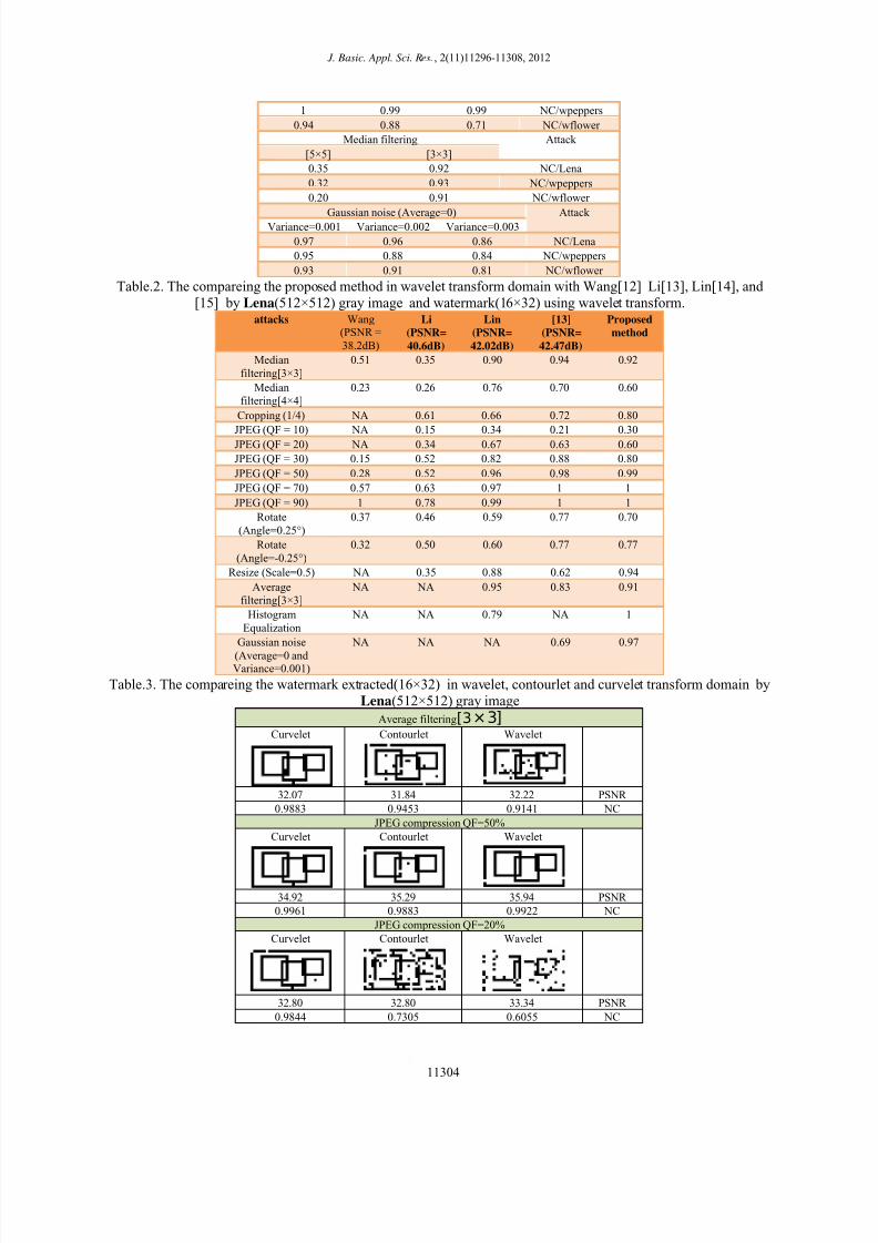
Table.2. The compareing the proposed method in wavelet transform domain with Wang[12] Li[13], Lin[14], and
[15] by Lena(512×512) gray image and watermark(16×32) using wavelet transform.attacks Wang
(PSNR =
38.2dB)
Li
(PSNR=
40.6dB)
Lin
(PSNR=
42.02dB)
[13]
(PSNR=
42.47dB)
Proposed
method
Median
filtering[3×3]
0.51 0.35 0.90 0.94 0.92
Median
filtering[4×4]
0.23 0.26 0.76 0.70 0.60
Cropping (1/4) NA 0.61 0.66 0.72 0.80
JPEG (QF = 10) NA 0.15 0.34 0.21 0.30JPEG (QF = 20) NA 0.34 0.67 0.63 0.60
JPEG (QF = 30) 0.15 0.52 0.82 0.88 0.80
JPEG (QF = 50) 0.28 0.52 0.96 0.98 0.99
JPEG (QF = 70) 0.57 0.63 0.97 1 1
JPEG (QF = 90) 1 0.78 0.99 1 1
Rotate
(Angle=0.25°)
0.37 0.46 0.59 0.77 0.70
Rotate
(Angle=-0.25°)
0.32 0.50 0.60 0.77 0.77
Resize (Scale=0.5) NA 0.35 0.88 0.62 0.94
Average
filtering[3×3]
NA NA 0.95 0.83 0.91
Histogram
Equalization
NA NA 0.79 NA 1
Gaussian noise
(Average=0 and Variance=0.001)
NA NA NA 0.69 0.97
Table.3. The compareing the watermark extracted(16×32) in wavelet, contourlet and curvelet transform domain by
Lena(512×512) gray image
Average filtering[3×3]
Curvelet Contourlet Wavelet
32.07 31.84 32.22 PSNR
0.9883 0.9453 0.9141 NC
JPEG compression QF=50%
Curvelet Contourlet Wavelet
34.92 35.29 35.94 PSNR
0.9961 0.9883 0.9922 NC
JPEG compression QF=20%
Curvelet Contourlet Wavelet
32.80 32.80 33.34 PSNR
0.9844 0.7305 0.6055 NC
11304

7/27/2019 Curve Let
http://slidepdf.com/reader/full/curve-let 10/13
Bazargani et al., 2012
Median filtering[3×3]
Curvelet Contourlet Wavelet
35.31 3518 35.84 PSNR
0.9883 0.9492 0.9219 NC
Gaussian noise (Average=0 and Variance=0.001)Curvelet Contourlet Wavelet
5.71 29.80 29.85 PSNR
0.04 1 0.9727 NC
Salt and pepper noise (Strength=0.01)
Curvelet Contourlet Wavelet
5.71 25.38 25.40 PSNR
-0.02 0.9492 0.9375 NC
Speckle noise (Average=0 and Variance=0.001)
Curvelet Contourlet Wavelet
5.71 34.97 35.14 PSNR
-0.01 1 1 NC
Resize (Scale=0.5)
Curvelet Contourlet Wavelet
32.92 32.60 32.98 PSNR
0.9570 0.9141 0.9414 NC
Rotate (Angle=0.25°)
Curvelet Contourlet Wavelet
29.17 29.14 29.44 PSNR
0.9883 0.8828 0.7031 NC
Cropping (1/4)
Curvelet Contourlet Wavelet
11.78 11.79 11.79 PSNR
0.8242 0.6992 0.800 NC
Table.4. The compareing the proposed method in wavelet, contourlet and curvelet transform domain by
Lena(512×512) gray image and watermark(16×32)attacks Proposed method
Wavelet contourlet Curvelet
Median
filtering[3×3]
0.92 0.94 0.98
Cropping (1/4) 0.80 0.69 0.82
JPEG (QF = 10) 0.29 0.30 0.50
JPEG (QF = 20) 0.60 0.73 0.98
JPEG (QF = 30) 0.80 0.93 0.98
JPEG (QF = 50) 0.99 0.98 0.99
JPEG (QF = 70) 1 1 0.98
11305
7/27/2019 Curve Let
http://slidepdf.com/reader/full/curve-let 11/13
J. Basic. Appl. Sci. Res., 2(11)11296-11308, 2012
JPEG (QF = 90) 1 1 0.99
Rotate
(Angle=0.25°)
0.70 0.88 0.98
Rotate
(Angle=-0.25°)
0.77 0.84 0.96
Resize (Scale=0.5) 0.94 0.91 0.95
Average
filtering[3×3]
0.91 0.94 0.98
HistogramEqualization 1 0.92 -0.25
Gaussian noise(Average=0 and
Variance=0.001)
0.97 1 0.04
Salt and pepper noise
(Strength=0.01) 0.93 0.94 -0.02
Speckle noise(Average=0 and
Variance=0.001)
1 1 -0.01
Table.5. The compareing the proposed method in contourlet transform domain with Zhu[16] by Lena(512×512)
gray image and watermark (32×32). Attacks Zhu Proposed Method
Median filtering(3×3) 0.93 0.96
Gaussian noise(0,0.001) 0.96 0.99
Gaussian noise(0,0.005) 0.68 0.86Pepper&Salt noise
(density 0.001)
0.99 0.99
Pepper&Salt noise
(density 0.005)
0.88 0.96
Cropping (1/4) 0.84 0.68
JPEG(QF=40) 0.99 0.97
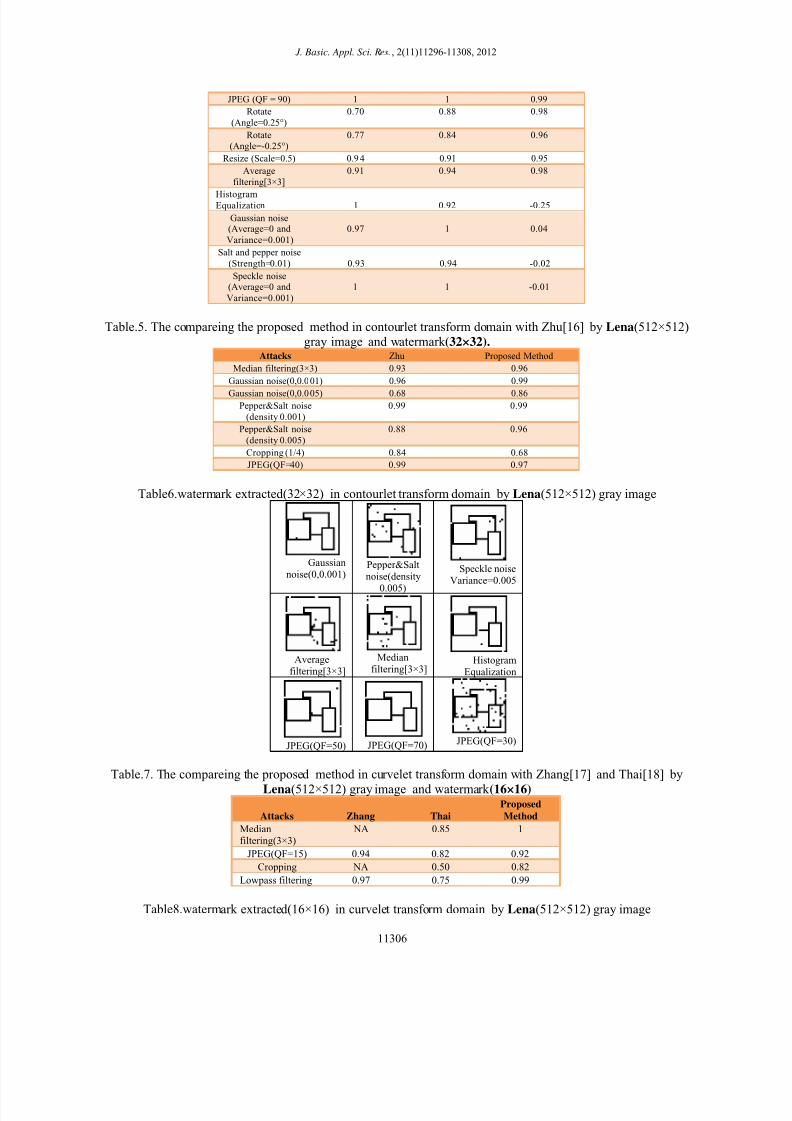
Table6.watermark extracted(32×32) in contourlet transform domain by Lena(512×512) gray image
Speckle noiseVariance=0.005
Pepper&Saltnoise(density
0.005)
Gaussiannoise(0,0.001)
Histogram
Equalization
Medianfiltering[3×3]
Average
filtering[3×3]
JPEG(QF=30)
JPEG(QF=70)
JPEG(QF=50)
Table.7. The compareing the proposed method in curvelet transform domain with Zhang[17] and Thai[18] by
Lena(512×512) gray image and watermark (16×16)
Attacks Zhang Thai
Proposed
Method
Medianfiltering(3×3)
NA 0.85 1
JPEG(QF=15) 0.94 0.82 0.92
Cropping NA 0.50 0.82
Lowpass filtering 0.97 0.75 0.99
Table8.watermark extracted(16×16) in curvelet transform domain by Lena(512×512) gray image
11306

7/27/2019 Curve Let
http://slidepdf.com/reader/full/curve-let 12/13
Bazargani et al., 2012
Resize(Scale=0.5)
Rotate
(Angle=0.25°)
Cropping (1/4)
JPEG(QF=20)
Median
filtering[3×3]
Average
filtering[3×3]
JPEG(QF=10)
JPEG(QF=30)
JPEG(QF=90)
5. CONCLUSIONS
In this paper, a blind wavelet- contourlet- curvelet tree-based watermarking method is presented. We
embed a watermark bit by quantizing the coefficients. The experimental results have showed that the algorithm has better invisibility and has stronger robustness when it is attacked by some attacks and a good resistance to many
image attacks such as JPEG compression, filtering, and rotation
REFERENCES
[1] Ali Al Haj, 2007, Combined DWT-DCT Digital Image Watermarking, J. Computer Science, Vol. 3, pp740-746
[2] V. Potdar, S.Han, E.Chang, 2005," A Survey of Digital Image Watermarking Techniques" IEEE International
Conference on Industrial Informatics,pp 709-716.
[3] A.Piva, M.Barni, F.Bartolini,1998 " Copyright protection of digital image by means of frequency domainwatermarking", SPIE Conference on Mathematics of Data/Image Coding, Compression and Encryption,pp.25-
35.
[4] Y. P. Hu and D. Z. Han, 2004 “Wavelet-based readable watermarking algorithm using adaptive quantization,”
Proc. IEEE Int. Conf. Image Machine Learning and Cybernetics, vol. 7, pp. 4076-4080.
[5] Zhao, Wang ,Hu and Lian, 2009 "Digital Image Watermarking Algorithm Based on Wavelet Transform" Third
International Symposium on Intelligent Information Technology Application, IEEE computer society
[6] I.rube, M.nasr, M. naim, M.farouk, 2009, "Contourlet versus Wavelet Transform for a Robust Digital Image
Watermarking Technique" , word academy of science, Engineering and Technology 60
[7] Do, Minh N, Vetterli M. 2005 " The contourlet Transform: An efficient directional multiresolutional image
representation", In IEEE transactions on Image Processing, Institute of Electrical and Electronic Engineers,
New York, PP.2091-2106.
[8] E.J.Candes, L.Demanet, D.L.Donoho, L.Ying, 2006 ,Fast Discrete Curvelet Transforms, SIAM Mult. Model.Sim.5-3(2006) 861899.
[9] E.J.Canded and D.L.Donoho, 2004, New tight frames of curvelets and optimal representationds of objects with
piecewise-C2 singularities. Comm. On Pure and Appl. Math. 57(2004),219-266.[10] Tao.J , Xin.zh , 2008, " Research and application of image denoising method based on curvelet transform", the
international archives of the phtogrammetry, remote sensing and spatial information sciences
.vol.XXXVII:PART B2.
[11] L.Ying,"CurveLab2.0, 2005, " California Institute of Technology.
[12] Wang S.H and Lin Y.P ,Feb.2004 “Wavelet Tree Quantization for Copyright Protection Watermarking,” IEEE
Trans. Image Processing, vol.13,pp,154-165
11307
7/27/2019 Curve Let
http://slidepdf.com/reader/full/curve-let 13/13
J. Basic. Appl. Sci. Res., 2(11)11296-11308, 2012
[13] E.Li, H.Liang and X.Niu, 2006," Blind Image Watermarking Scheme Based on Wavelet Tree Quantization
Robust to Geometric Attacks", In Proceedings of the IEEE WCICA, vol.2,pp.10256-10260,doi:
10.1109/WCICA.2006.1714009.
[14] Lin.W.H, Wang.Y.R, Horng.S, Kao.T, Yi Pan, 2009, A blind watermarking method using maximum wavelet
coefficient quantization, Expert Systems with Applications, vol. 36, no. 9, pp.11509-11516.
[15] M.J.Dehghani, M.Hajizadeh and M.S.Helfroush, 2010,"Blind Watermarking Scheme Based on Remainder of Distance Vector of Wavelet Coefficients" IEEE, International Conference on Signal Processing
Systems(ICSPS).
[16] S. m. Zhu, J. m. Liu, , 2009 “A Novel Blind Watermarking Scheme in Contourlet Domain Based on Singular
Value Decomposition ,“ Proc. WKDD '09, vol.1, pp. 672-675.
[17] Z.Zhang, H.Wei and J.Zhang, 2006 " Digital image watermark algoritm in the curvelet domain" International
Conference on Intelligient Information Hiding and Multimedia pp.105-108
[18] Thai .D .h, Kei.I, Harak.H, Chen.Y.W, Nagata.Y, Nagata.Z. 2007,"curvelet –Domain image watermarking
based on edge embedding". Leature notes in computer science , vol,4693,pp.311-312
11308