curt madsen, p.e. trc environmental corporation november 28, 2012 landfill leachate collection...
TRANSCRIPT
Curt Madsen, P.E. TRC Environmental Corporation
November 28, 2012
Landfill Leachate Collection System Design
CEE 427
• Primary criteria…route leachate off liner to collection sump• Designed to limit head to 12 inches or less • Minimum base slope of 0.5%• Maximum flow distance to collection pipe of 130 feet• Minimum hydraulic conductivity of 1x10⁻² cm/s of drainage
layer aggregate• Minimum 1-foot-thick select aggregate fill drainage layer
2
General (Referencing Wisconsin s. NR 504.06(5))
3
• Used to size pipes, pumps, tank storage volume, estimate treatment costs
• Based on NR 512.12(3)(a) and (b)– 6 inches/year for unclosed areas– 1 inch/year for closed areas (with composite cover)
• Values above are more conservative than Help Model
4
Leachate Generation

• Consists of select aggregate layer, collection piping, sumps, FM transfer pipes and cleanout access piping
• Select aggregate drainage layer placed on geotextile cushion (min 12 oz/yd)
• Aggregate is used to allow for future leachate recirculation• Drainage layer consists of rounded to sub-angular (then use
16 oz/yd) stone with Unif. Coeff. < 4; max. particle diam. of 1.5 inches; a max. of 5% passes #4 sieve; no more than 5% passing #200 sieve
• Minimum pipe slope is 0.5% (typically greater)• Collection piping placed in V-trenches (per NR 504.06(5)(d))
5
Leachate Collection System
6
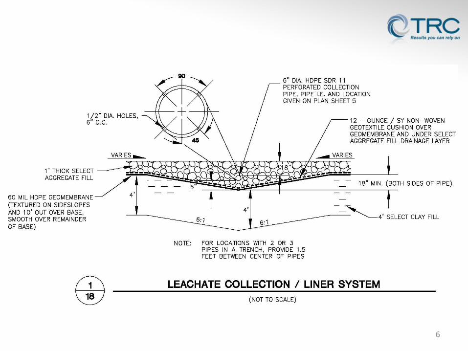
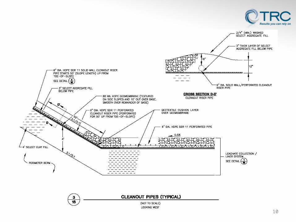
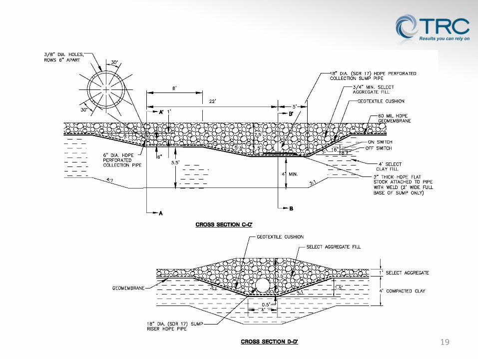
• Piping consists of 6-inch diameter perforated SDR 11 HDPE pipe
• Pipe strength calculations (attached)• Perforated 0.5-inch holes, 2 rows set at 45 degrees and placed
@ 6-inches• Minimum of 6-inches of bedding material placed under pipe• Minimum of 18-inches of bedding material placed over pipe• Performed piping and permeability calculations to confirm
required hydraulic conductivity without excessive migration of fines
7
Leachate Collection System (continued)
8
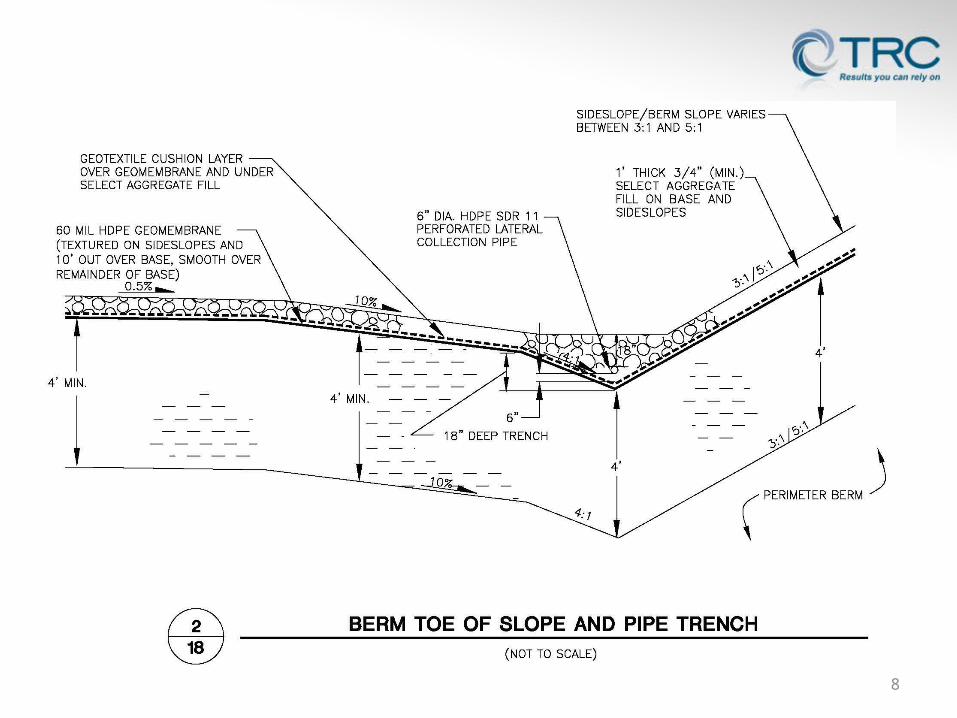
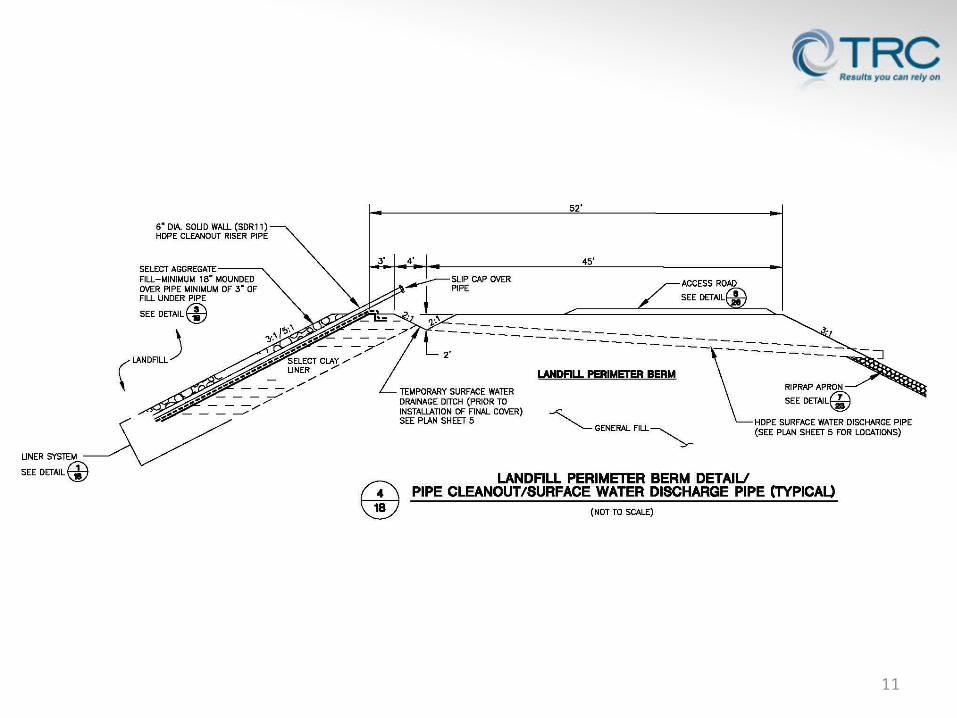
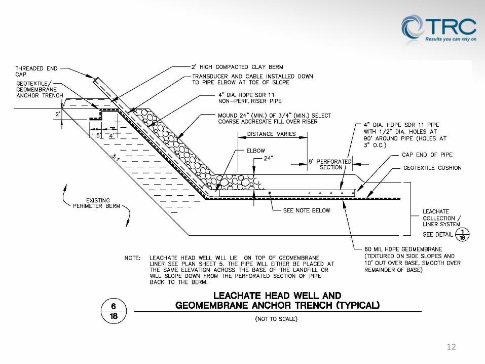
• Collection pipes extend to sump• Perimeter cleanouts installed at both ends of pipe• Lower portion of cleanout on side-slope may be perforated• Leachate headwell
9
Leachate Collection System (continued)
10
11
12
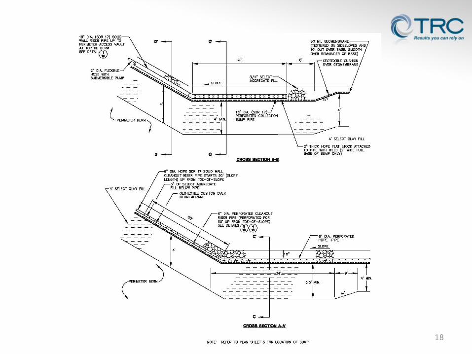
• Leachate drains to collection sumps (fill with similar select aggregate)
• Sump volume sized to satisfy NR 504.06(5)(j) and accommodate sediment
• Inclined riser (18-inch-diameter SDR-17 HDPE) terminates into a vault
• Sump area must accommodate remedial installations• Use back-flow preventer valves• Submersible pumps / controlled with transducers / run-time
meter
13
Leachate Removal and Storage System
• Provide valves to isolate systems• Pumps (place on PE skid plate) • From vault leachate transferred to tank via forcemain (double
cased)• Minimum 4-day tank storage volume required (secondary
containment)
14
Leachate Removal and Storage System (continued)
15
16
17
18
19

• Maximum “clean-out” length may not exceed 2,000 feet (NR 504.06(6))
• Minimum 0.5% slope after accounting for primary and secondary settlement (100 yr)
• Similar bedding material requirements• Utilize sweep bends (minimum radius of 10 pipe diameters)
20
Extended Length Leachate Collection Line Considerations
• Pipe strength calculations– Purpose, methodology, assumptions, results, references– Figures– Calculations
• Watkins’ Method• Modified Iowa Formula• Corrugated pipe (downslope flumes)
• Piping and permeability calculations– Purpose, methodology, assumptions, results, references– Calculations
21
Attachments

Questions?Curt Madsen, P.E.P: 608-826-3640 | E: [email protected]